Effect of Low Cycle Fatigue Predamage on Very High Cycle Fatigue Behavior of TC21 Titanium Alloy
by
Baohua Nie
1, 
Zihua Zhao
2,*,
Yongzhong Ouyang
3,
Dongchu Chen
1,
Hong Chen
1,
Haibo Sun
1 and
Shu Liu
1 1
School of Materials Science and Energy Engineering, Foshan University, Foshan 528000, China
2
School of Materials Science and Engineering, Beihang University, Beijing 100191, China
3
School of Environmental and Chemical Engineering, Foshan University, Foshan 528000, China
*
Author to whom correspondence should be addressed.
Materials 2017, 10(12), 1384; https://doi.org/10.3390/ma10121384
Submission received: 28 October 2017
/
Revised: 24 November 2017
/
Accepted: 29 November 2017
/
Published: 4 December 2017
Abstract
:The effect of low cycle fatigue (LCF) predamage on the subsequent very high cycle fatigue (VHCF) behavior is investigated in TC21 titanium alloy. LCF predamage is applied under 1.8% strain amplitude up to various fractions of the expected life and subsequent VHCF properties are determined using ultrasonic fatigue tests. Results show that 5% of predamage insignificantly affects the VHCF limit due to the absence of precrack, but decreases the subsequent fatigue crack initiation life estimated by the Pairs law. Precracks introduced by 10% and 20% of predamage significantly reduce the subsequent VHCF limits. The crack initiation site shifts from subsurface-induced fracture for undamaged and 5% predamaged specimens to surface precrack for 10% and 20% predamaged specimens in very high cycle region. Furthermore, the predicted fatigue limits based on the El Haddad modified model for the predamaged specimens agree with the experimental results.
1. Introduction
Titanium alloy is widely used for aeronautical structures because of its high specific strength, toughness, and damage tolerance [1]. Throughout the ultra-long time service, the components are subjected to high frequency, low amplitude, and cyclic load; thus, a very high cycle fatigue (VHCF) of titanium alloys in the life regime beyond 107 cycles has been drawing a worldwide attention [2,3]. In practice, aeronautical structures may consist of low cycles fatigue (LCF) resulting from the takeoff and dropdown of the aircraft, and VHCF generated by high-frequency vibrations. A “damage tolerant” design for LCF would be to relate the remaining life based on crack propagation to an inspectable flaw size. However, direct application of such an approach cannot work for “pure” VHCF because the required inspection sizes are well below the state-of-the-art in nondestructive inspection (NDI) techniques. Specially, fatigue damage occurred in specimen subsurface for VHCF is difficult to inspect by the traditional NDI techniques. VHCF requires a relatively large fraction of life for initiation. In addition, crack propagation times to failure could be extremely short due to the high frequencies in VHCF, and the resultant inspection intervals would be too short to be practical. Thus, interest is increasing not only in the capability of pure VHCF but also in that of VHCF combined with LCF fatigue damage.
Recently, few studies have been devoted to the LCF/VHCF combined fatigue behavior of titanium alloys. Hang [4,5] indicated that LCF load significantly decreased the VHCF strength of low carbon-manganese steel, and developed continuum damage mechanics model to evaluate cumulative damage of LCF and VHCF. Mayer [6] showed that the deleterious influence of low load cycles below constant amplitude fatigue limit was underestimated for very high cycle fatigue damage of 100Cr6 steel under variable amplitude (VA) loading condition. However, the effect of LCF load on VHCF fracture mechanism for titanium alloys is not well understood. As for the low carbon-manganese steel, the LCF and VHCF cracks are incline to initiate from the specimens surface, and the fatigue damage accumulation under the LCF/VHCF combined fatigue accelerated the crack initiation. VHCF cracks of high strength titanium alloys mainly induced from the heterogeneous microstructure, such as primary α phase [7,8,9] as well as super grain (grain clusters with similar orientation) [10], whereas LCF cracks are usually initiated from the specimen surface due to the surface machining flaws and persist slip bands. The competition between the LCF damage and materials interior heterogeneous microstructure is focused on LCF/VHCF combined fatigue of high strength titanium alloys.
A practical problem arises in designing against VHCF with the occurrence of high stress transients (LCF loading), which may not lead to failure during the design life, but may degrade the capability of the material regarding its VHCF resistance. Treating VHCF as pure failure modes in fatigue design practice is nonconservative throughout ultra-long life service. In the past years, a Kitagawa–Takahashi (K–T) diagram joined by the El Haddad model can be useful in evaluating the potential for a crack to reduce the HCF capability of a material [11]. The investigations showed that the effect of LCF on HCF limits is affected by not only LCF crack depth, but also the stress ratio R or the residual stress ahead of the crack tip [12]. Cycling at high stress for up to 25% of life has little effect on the HCF strength for Ti6Al4V. However, the HCF strength is reduced by an average of 19% when subjected to prior cycles followed by a stress relief process. Recently, Zerbst [13] modified the El Haddad model based on the cyclic R curve, which can be described by giving the fatigue crack propagation threshold as a function of the crack extension. Compared to HCF, VHCF has lower fatigue limits at 109 cycles, and has lower tolerance to materials defects. It is expected the LCF damage can significantly affect VHCF properties.
The effect of LCF predamage on VHCF behavior of TC21 titanium alloy was investigated in the present work. The LCF up to various fractions of expect life was used to introduce predamage, and then the VHCF behaviors were subsequently studied. This work aimed to enable fundamental understanding of very high cycle fatigue fracture mechanism combined with LCF predamage.
2. Experimental Procedures
2.1. Materials
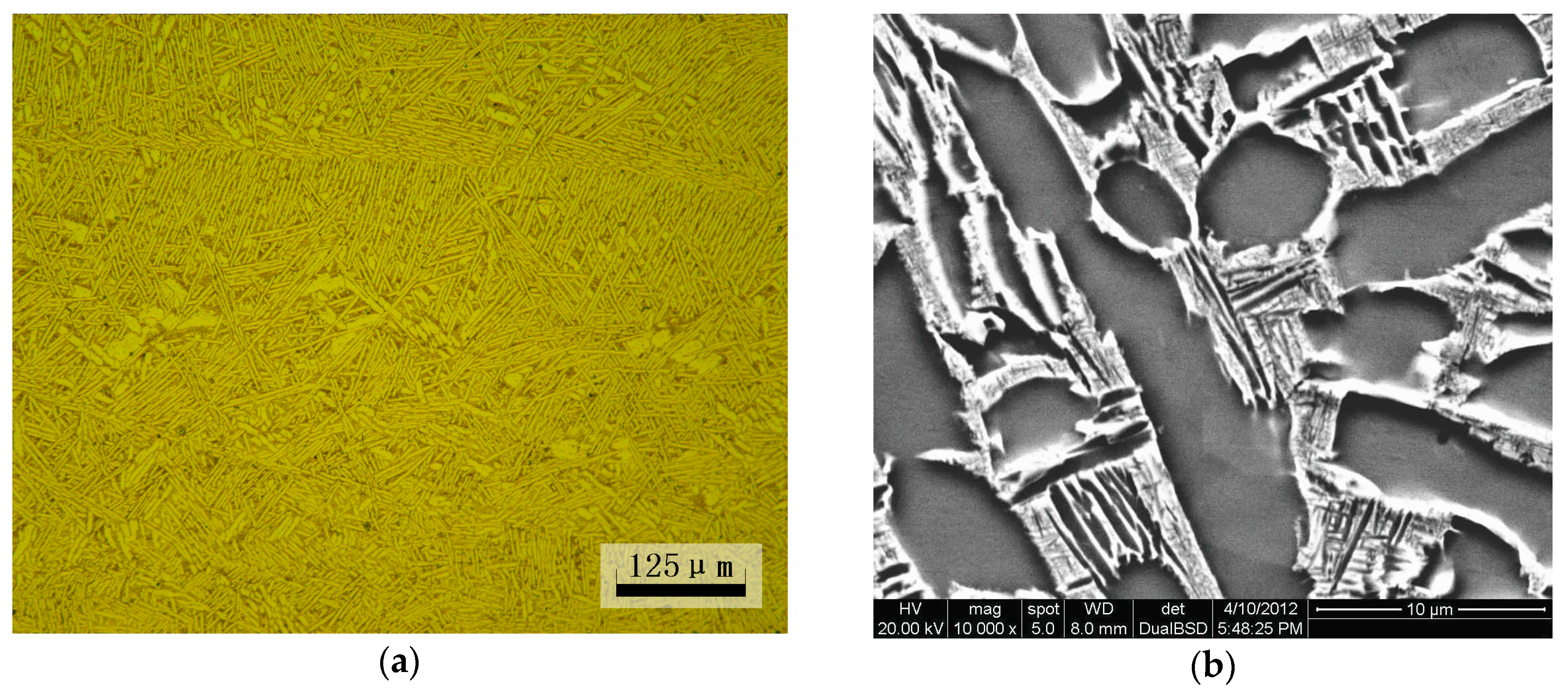
The material used in this study was TC21 titanium alloy with a nominal chemical composition of Ti-6Al-2Sn-2Zr-3Mo-1Cr-2Nb. Heat treatment was as follows: 900 °C for 2 h, air quenching, and then 600 °C for 4 h, air quenching. The heat-treated material had a high yield strength of 970 MPa and tensile strength of 1070 MPa. A double lamellar basket weave microstructure was observed (Figure 1).
2.2. Surface Treatment
The specimens underwent electropolishing (EP) to remove the machining layers to observe fatigue damage morphology and eliminate its influence on fatigue behavior. Electropolishing was carried out in 59% methanol, 35% n-butanol, 6% perchloric acid under −20 °C temperature and 20–25 V voltage.
2.3. Fatigue Test
2.3.1. Ultrasonic Fatigue Test
Fatigue tests were carried out using an ultrasonic fatigue test machine (20 kHz) at a constant load ratio of R = −1. The ultrasonic fatigue testing method is an accelerated testing method with a frequency far beyond that of conventional fatigue experiments, which brings advantages of effectiveness and economy morphologies for very high cycle fatigue tests comparing with conventional tests method [14]. An ultrasonic generator transforms 50 or 60 Hz voltage signal into sinusoidal signal with 20 kHz; a piezoelectric converter excited by the generator transforms the electrical signal into longitudinal mechanical vibration with same frequency; an ultrasonic horn amplifies the vibration displacement in order to obtain the required strain amplitude in the middle section of specimen; a computer control system is necessary to control the load amplitude and acquire test data. The maximum displacement amplitude measured by means of a dynamic sensor is obtained at the end of the specimen, while the strain excitation in push–pull cycles (load ratio R = −1) reaches the maximum in the middle section of the specimen, which produces the required high frequency fatigue stress. In addition, a compressed air cooling gun is necessary to be used to prevent the temperature increasing of specimen in the tests.
Considering that the amplifier and the specimen must work at resonance, the specimen geometry was designed using the elastic wave theory. Figure 2 shows the geometries of the fatigue specimens and its dimensions.
2.3.2. LCF Fatigue Tests
The specimen were tested in uni-axial reversed strain amplitude in a conventional hydraulic fatigue machine (Instron 8801, Instron Company, Boston, MA, USA). Considering the dimensions of ultrasonic fatigue test specimens (Figure 2), a LCF test was controlled under transverse diameter deformation. The diameter deformation strain εdia can be converted to longitudinal plastic strain εp and longitudinal total strain ε through the formulas below [4]:
where E, σ, νe and νp are the Young modulus, longitudinal stress, elastic Poisson coefficient and plastic Poisson coefficient and its value is always 0.5, respectively.
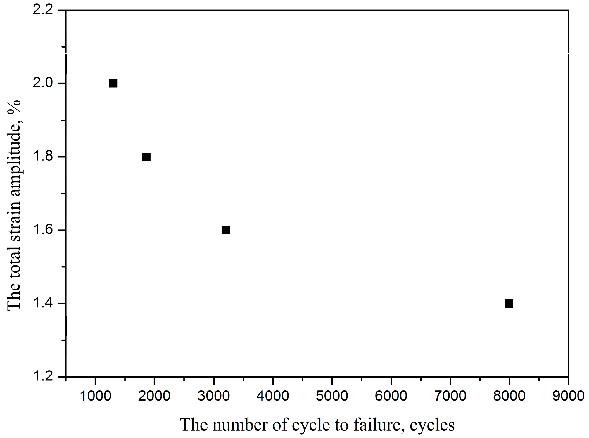
In all LCF tests, a reversed triangle strain waveform was submitted to the specimens. The failure condition is set as its maximum stress decreasing 20% after its cyclic saturation. Figure 3 shows the fatigue life is 1864 cycles at 1.8% strain amplitude. Furthermore, the fatigue damage morphology of different stage fatigue were observed using a video microscope.
2.3.3. LCF/VHCF Combined Fatigue Tests
In order to investigate the effect of LCF predamage on behavior of VHCF for TC21 titanium alloy, specimens were submitted to a same prior 1.8% strain range (strain ratio: −1). LCF predamage was applied onto ultrasonic fatigue specimens at 1.8% strain range for 90 cycles (5% of fatigue life), 180 cycles (10% of fatigue life), 360 cycles (20% of fatigue life), respectively. The subsequent VHCF tests are performed by using ultrasonic fatigue test machine at R = −1, room temperature.
2.3.4. Fatigue Precrack Propagation
Fatigue precrack was obtained by LCF at 1.8% strain range and the ratio of −1. The propagation of precrack under subsequently low stress amplitude were observed using a video microscope. Fatigue crack propagation rate was expressed as follows:
where is crack depth at cycle number Ni, which is supposed to be equal to 0.8c [15], and a surface crack with length 2c was obtained using the video microscope.
3. Results
3.1. LCF Damage of TC21 Titanium Alloy
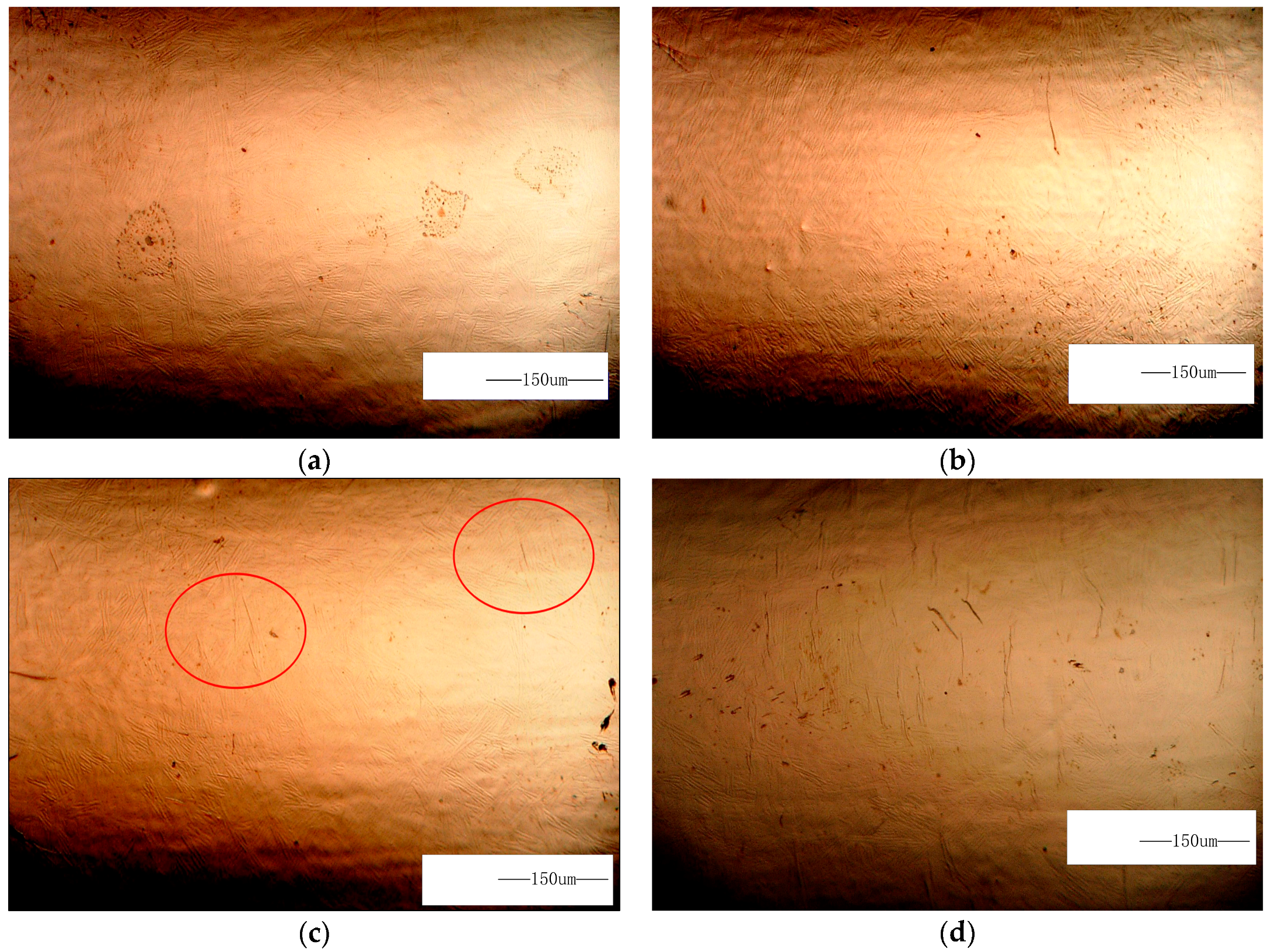
The LCF surface damage evolution of TC21 titanium alloy under 1.8% strain amplitude is shown in Figure 4. No surface crack is observed in 90 cycles (5% of LCF life) until the number of cycles increase to 180 cycles (about 10% of LCF life). However, the number of microcrack significantly increase in 360 cycles (about 20% of LCF life), then these microcrack were expanded to merge until the specimen is broken.
The fracture surfaces of specimens under 1.8% strain range, Nf = 1864 cycles are shown in Figure 5. LCF cracks initiate from multiple sites on the sample surface, and a radial ridge pattern parallel to the crack propagation direction is observed on the fracture surface (Figure 5a). Some small elliptical planes have traces of friction at the fatigue crack initiation site (Figure 5b,c), indicating that these small cracks were expanded to merge to fracture, in accordance with Figure 4d. Cleavage morphology is observed near the small planes (Figure 5c) and typical fatigue striation is displayed on fatigue crack steady propagation (Figure 5d).
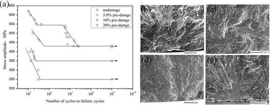
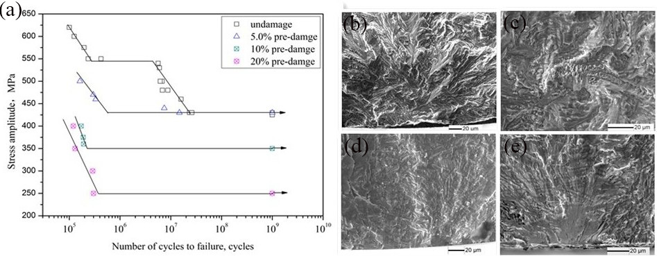
3.2. S-N Curves After Fatigue Predamage
Figure 6 shows that the S-N curve of undamaged specimens exhibit a stepwise shape, which is similar to the references [16,17]. However, in the predamaged specimens, there is a knee of horizontal lines for their S-N curves in the regime above 105 cycles. Five percent of LCF predamage insignificantly affects the fatigue limit but remarkably decreases fatigue life above fatigue limit compared with undamaged specimens. Fatigue life at 500 MPa stress amplitude is reduced by two orders of magnitude after 5% of LCF predamage. Fatigue limits for 10%, 20% and 50% of the expected life predamage decrease from 430 MPa to 350 MPa, 250 MPa and 230 MPa for the undamaged specimens, respectively, and the fatigue limit of 20% predamage decreases up to 42%, indicating that treating VHCF as pure failure modes in fatigue design practice is nonconservative throughout ultra-long life service. It is should be noted that the decrease effect due to LCF for TC21 titanium alloy is stronger than its for A42 steel [4,5] in VHCF, which can be attributed to the stronger decrease effect in VHCF for high strength titanium alloys [9]. However, it was reported that the LCF predamage with high R value insignificantly affects fatigue limit because of its overloading effect [18,19]. In this paper, residual compressive stress is introduced at the precrack tip because of tensile overload; however, the precrack that acts as a blunt notch yields a residual tensile stress due to the high compression overload for a stress ratio of −1. Thus, the overloading effect of the alloy is significantly reduced by the residual tensile stress.
3.3. SEM Observation of the Fracture Surface
As is showed in Figure 7, fatigue crack of TC21 titanium alloy in the less than 106 cycles region initiates from the sample surface. However, subsurface crack initiation occurs in longer than 106 cycles. α/β lamellar morphology are observed at the crack initiation site where fine granular area (FGA) is found along the α lamellar (Figure 8). The FGA morphology of TC21 titanium alloy are similar to those of high-strength steels [20], although nonmetallic inclusions are not observed at the FGA center.
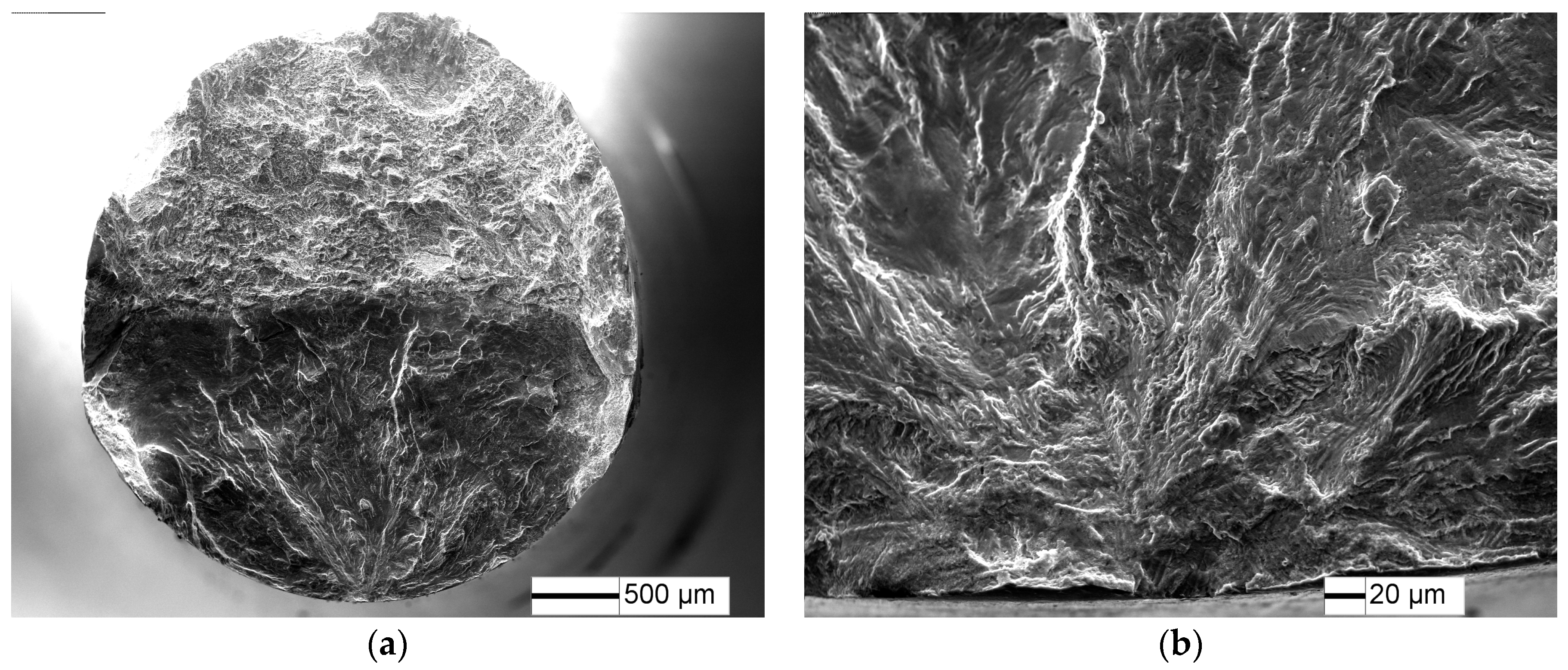
The typical fatigue fracture surfaces of the 5% predamaged specimens are shown in Figure 9 and Figure 10. Fatigue crack initiates from the specimen surface at 470 MPa stress amplitude (Figure 10), while the fatigue crack tends to initiate from the specimen subsurface for an undamaged specimen (Figure 8). Radial ridge pattern parallel to the crack propagation direction is displayed on the fracture surface. However, fatigue crack initiates from the specimen subsurface at VHCF limit stress amplitude (430 MPa), and a fine granular area is observed at the crack initiation site (Figure 10), which has similar crack initiation morphology to undamaged specimens.
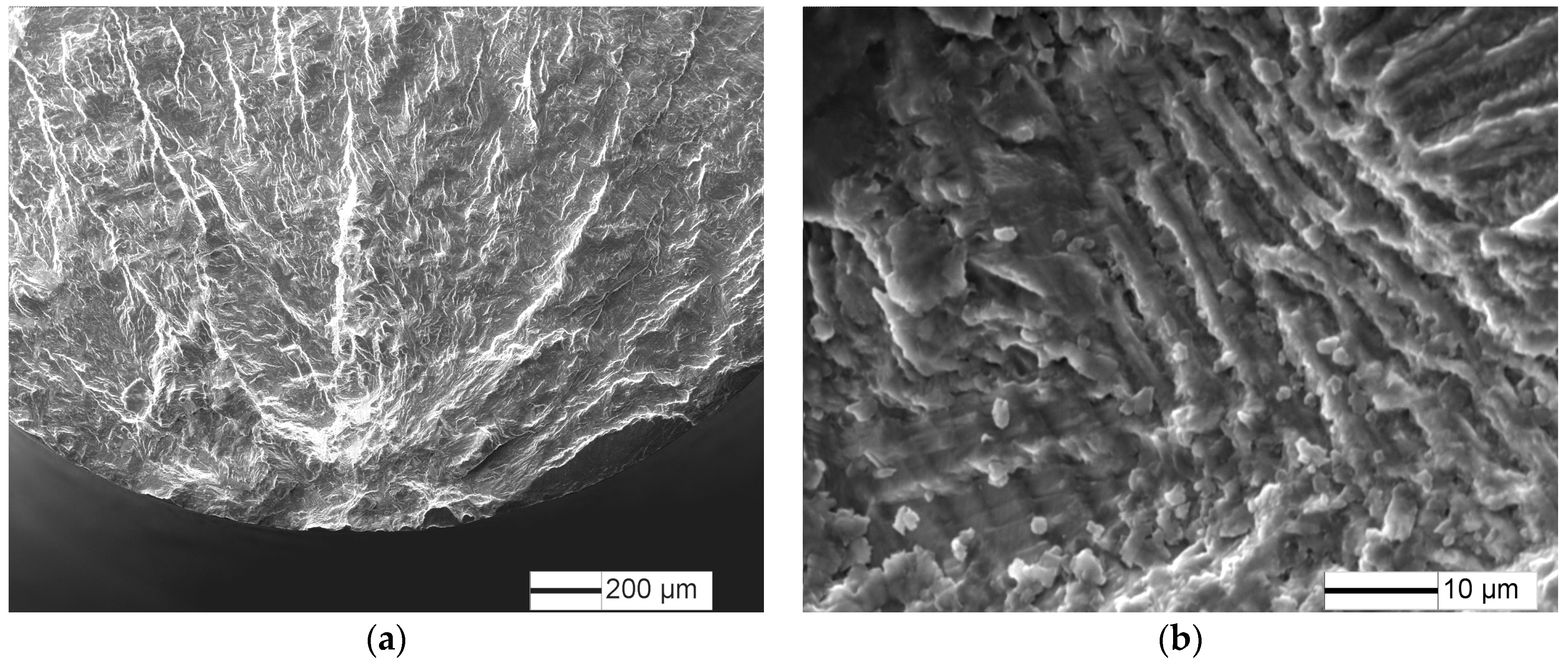
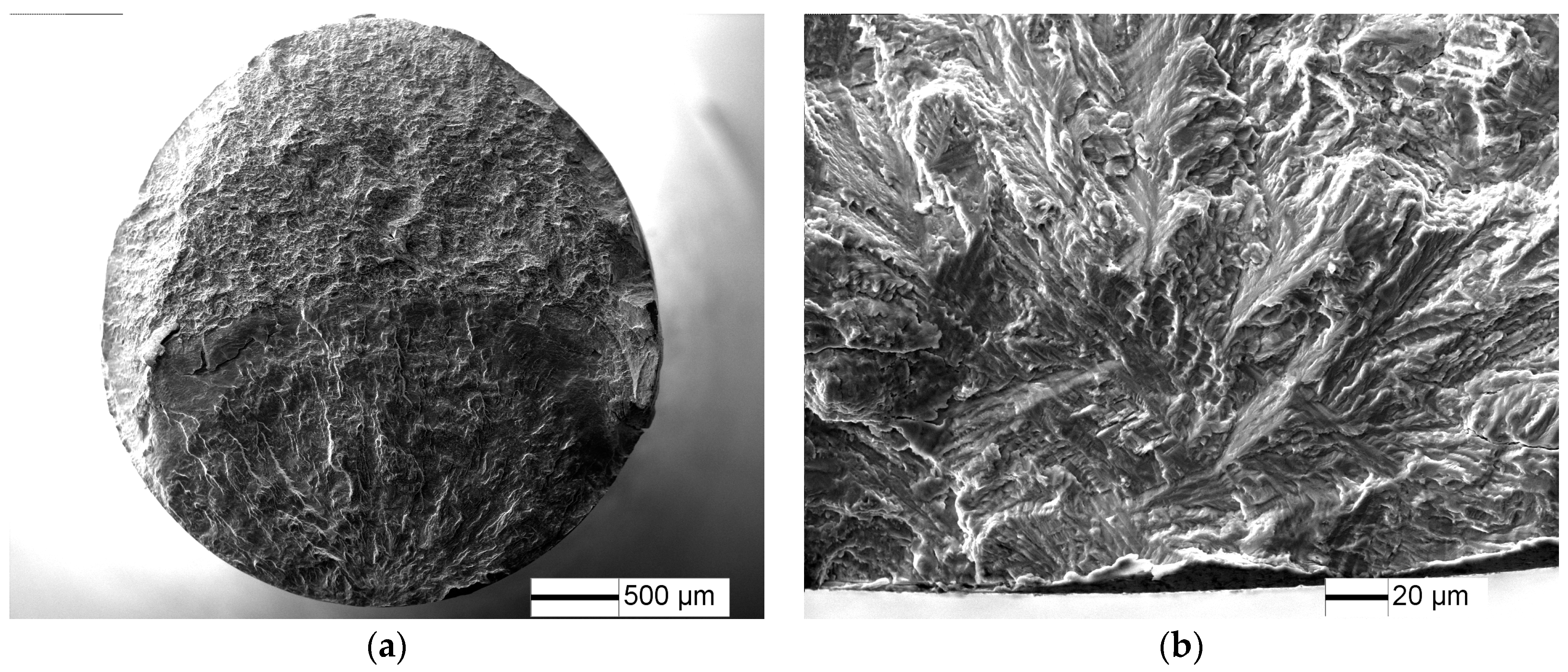
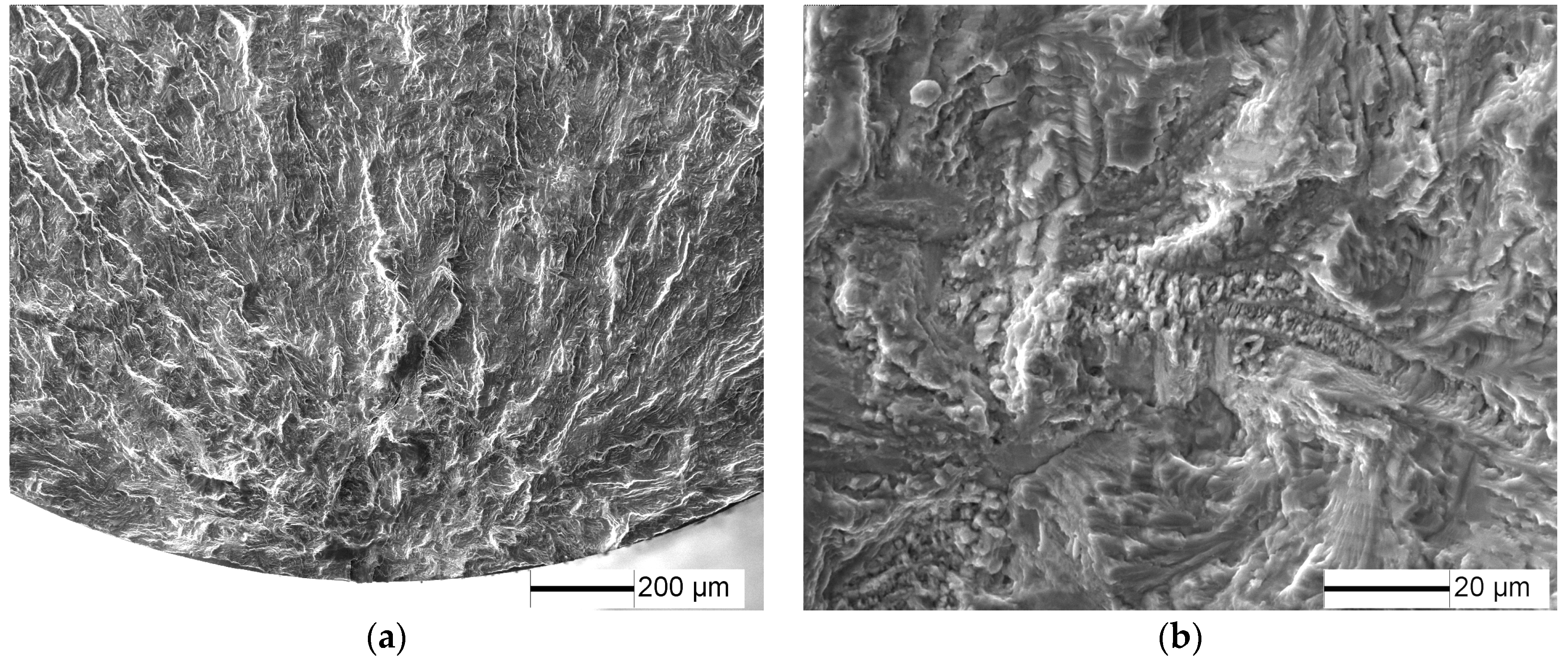
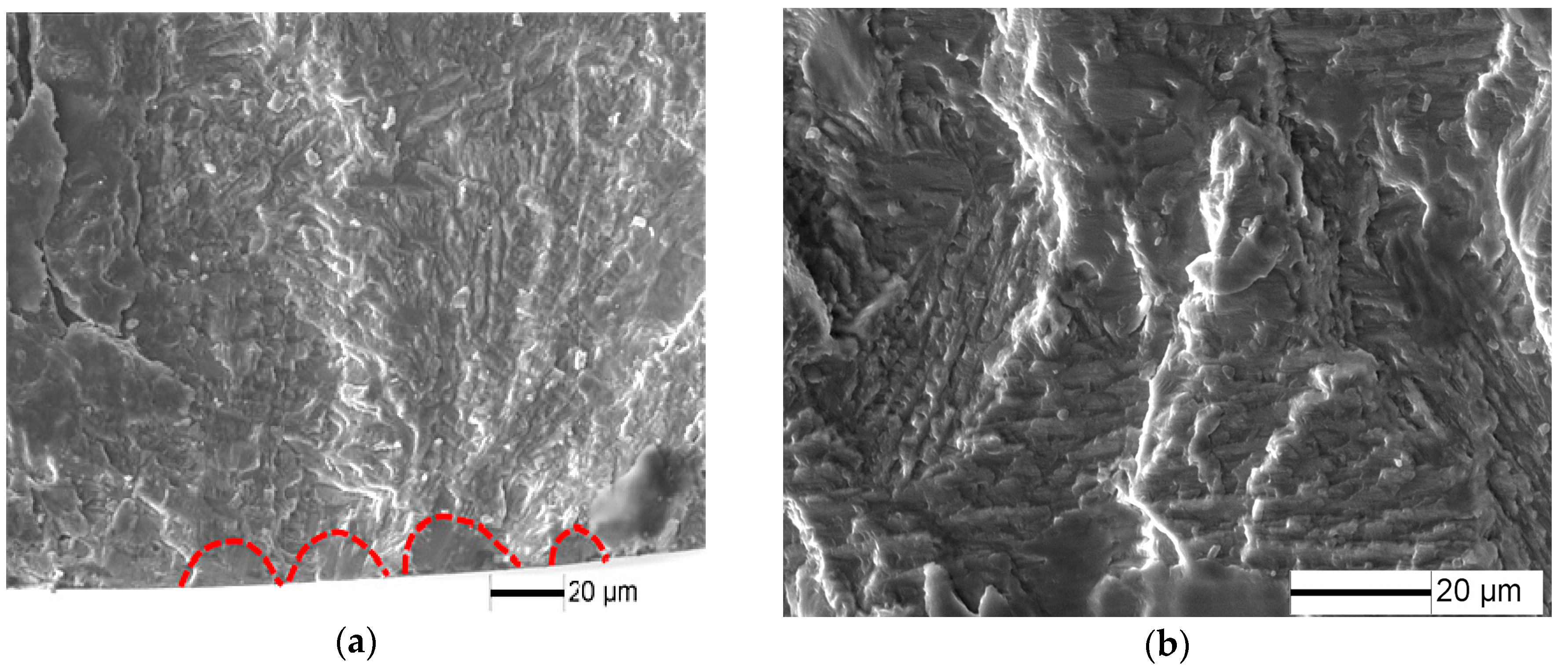
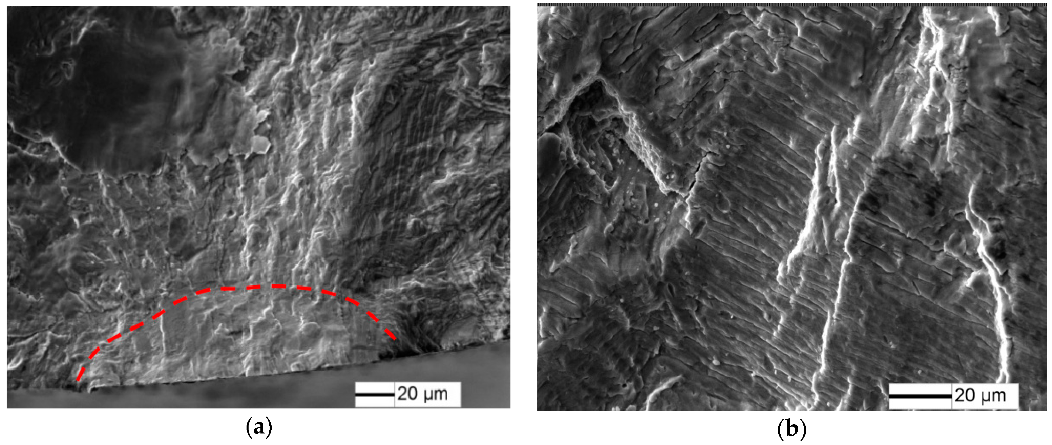
Fatigue fracture surfaces of 10%, 20% and 50% predamaged specimens at low stress amplitude are shown in Figure 11, Figure 12 and Figure 13. Fatigue crack initiates from the specimen surface, and a small elliptical plane with traces of friction is observed at the fatigue crack initiation site (Figure 11a, Figure 12a and Figure 13a), similar to that of LCF crack. The depth of the small plane is approximately 14.7 µm, 41.5 µm and 49.3 µm, respectively. Moreover, crack-propagation morphology is observed outside the small plane at the crack initiation site. The crack-propagation morphology is associated with α/β lamellar microstructure generated by the subsequent low stress fatigue (Figure 11b, Figure 12b and Figure 13b), rather than the cleavage morphology generated by LCF. Therefore, the small plane at the crack initiation site is supposed to be formed from fatigue precracks.
4. Discussion
4.1. Effect of LCF Predamage on VHCF Fracture Mechanism
As for TC21 titanium alloy, the fatigue crack initiates from α lamellar (Figure 8) in the sample interior above 106 cycles. However, the VHCF crack initiation mechanism of TC21 titanium alloy with LCF predamage is depended on the LCF predamage and the subsequent stress amplitude in VHCF. For 5% of predamage, the fatigue precrack is not formed by the fatigue predamage, however, it reduces the crack initiation phase and then decreases its fatigue life. As for the 1.8% strain amplitude, the corresponding stress can be approached to yield stress, and plastic deformation accumulation takes place during the LCF predamage. Thus, the slip systems can be activated by plastic deformation accumulation [21,22]. According to the weaken chain theory, a fatigue predamage site is a weak point, and then high cycle fatigue cracks can initiate from the predamage site due to the activating slip systems. However, a fatigue crack initiates from the specimen subsurface at low stress amplitude for 5% predamage specimens, indicating that fatigue early damage does not promote the surface crack initiation at low stress amplitude.
As precracks are introduced by LCF predamage, afatigue crack can be initiated from the precracks under subsequent low stress amplitude. In other words, the precracks can be restarted under low stress amplitude (Figure 11, Figure 12 and Figure 13). The effect of precracks on the fatigue limits can be estimated by El Haddad model. Recently, Zerbst [13] modified the El Haddad model and the Kitagawa–Takahashi diagram. The endurance limits stress range is obtained as:
which is the mathematical description of the K–T diagram. is the stress amplitude range. In ultrasonic fatigue with a mean load equal to zero (R = −1), only the tensile part of the cycle has a predominant effect on the fatigue crack propagation [23]. is replaced by stress amplitude . The geometry factor Y is equal to 0.728 for small semicircular surface cracks [13]. and are the initial closure-free crack size and the crack, and fatigue crack .
El Haddad’s equation has to be modified by adding an additional term :
The additional is simply determined by:
The intrinsic fatigue propagation threshold, , can be estimated by [24]. The term is introduced to fulfill the condition that for = 0. The intrinsic crack length is given by [11]:
In the absence of large defects, the initial closure-free crack ai can be referred as the arrested microstructurally short crack d1, which is given as:
The intrinsic fatigue propagation threshold, of TC21 alloy is calculated as 2.2 . The long crack propagation threshold of TC21 alloy is estimated about 2.8 [25], which is approach to the crack propagation threshold of Ti6Al4V [23]. It should be noted that is not much higher than , which can be explained by the very small closure effect when only the tensile part of the cycle load is considered at R = −1.
The term of di, , are calculated as 15.4 µm, 25.4 µm and 40.98 µm, respectively. The K–T diagram is shown in Figure 14. The precrack with the approximately 14.7 µm, 41.5 µm and 49.3 µm depth are introduced by 10%, 20% and 50% fatigue damage. According to Equation (4), the fatigue limit of TC21 alloy with 50% and 20% of predamage is about 230 MPa and 250 MPa, which well agrees with the experimental data (Figure 14). For 10% of predamage, the fatigue limit is estimated as 326 MPa with 6.8% error compared with the experimental data. This finding suggests that fatigue precrack plays a significant role in the reduction of fatigue strength. It is also indicated that the crack depth for the transition between short and long cracks is about 270 µm.
Furthermore, the cyclic plastic zone at the applied load level, and ω* can be estimated by Tirosh and Peles [26]:
For 10% of predamage, the stress intensity factor under stress amplitude 375 MPa is about 3.02 , and the plastic zone is 100 nm, which is smaller than the size of lamellar basketweave. This suggest that fatigue early crack growth is significantly influenced by the microstructure (Figure 12b), and fatigue crack is prone to grow towards the most preferred direction.
4.2. Effect of Fatigue Predamage on Fatigue Life
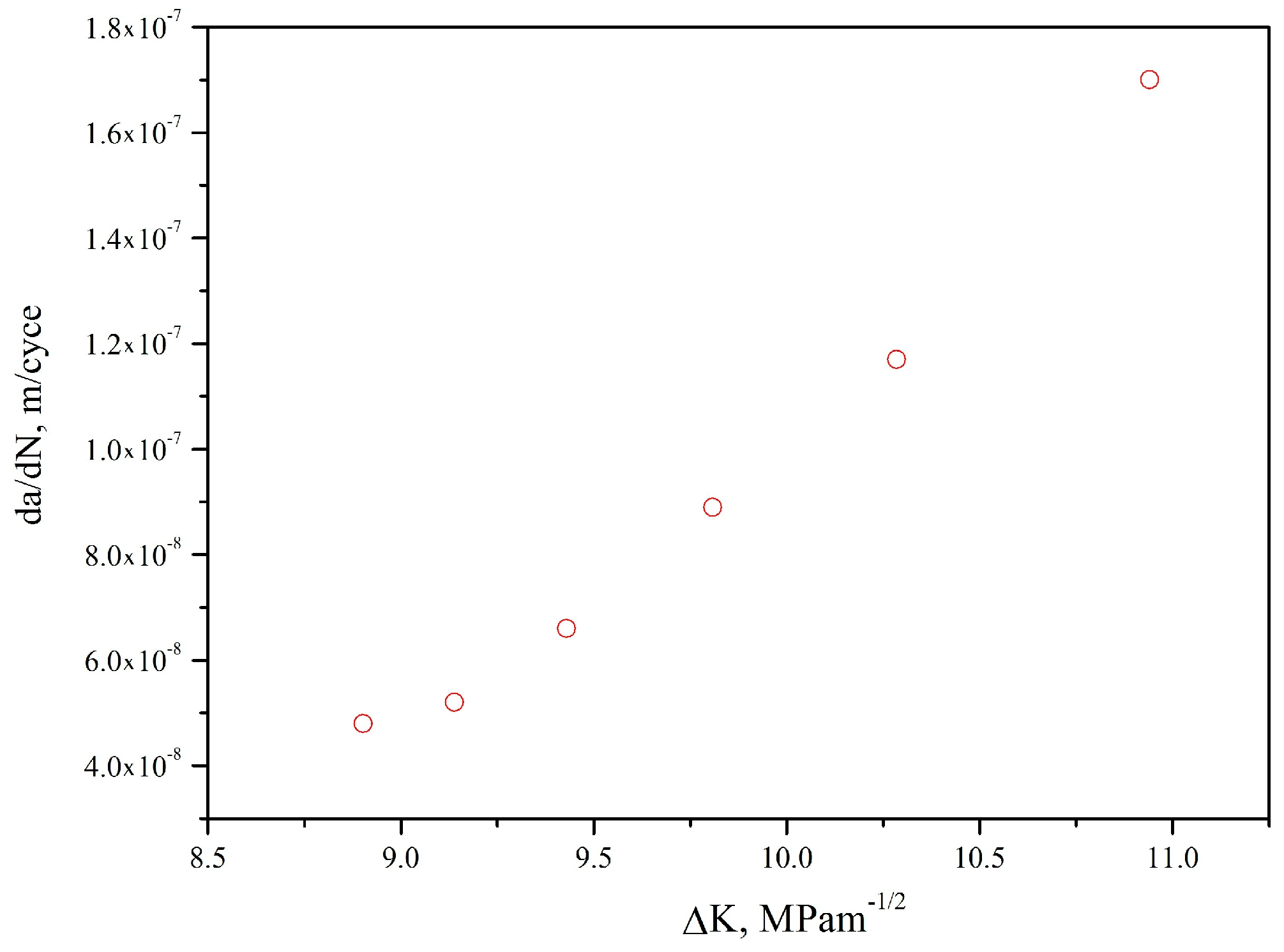
Fatigue precrack was obtained by LCF at 1.8% strain range and the ratio of −1. The propagation of precrack under a subsequently low stress amplitude were observed using a video microscope showed in Figure 15. The precrack propagation under a low stress amplitude follows Paris law (Figure 16) can be expressed as:
The precrack propagation life under a low stress amplitude can be estimated as:
where is the size of the fatigue fracture zone. C and m can be obtained by Equation (10).
The fatigue precrack acted as a small crack has a higher propagation rate than that of a long crack with the same nominal stress intensity factor range. An intrinsic crack length is added to the actual length of crack to unify the differences in the crack propagation rates between small and long cracks [26]. The crack propagation rate independent of crack size can be calculated by linear elastic fracture mechanics.
According to Equation (11), the crack propagation life of TC21 alloy for 5%, 10% and 20% LCF of predamage are shown in Table 1. The precrack propagation lives for 10% and 20% of LCF predamage samples account for a major portion of the expected life, which also indicate that the precrack directly propagate under subsequent stress amplitude. The number of cycles to failure for 10% predamage specimens under 350 MPa is about 2 × 10⁵ cycles, which shows that crack propagation times to failure could be extremely short due to the high frequencies in VHCF. Furthermore, the effect of high frequencies and low stress cannot be ignored for the structure with LCF predamage, although the stress amplitude is much lower than VHCF limits, which is consistent with Mayer’s research [6].
For 5% of LCF predamage specimens, where precracks are not introduced by LCF predamage, more than 20% of the expected life is consumed in the crack-propagation life. Considering that less than 1% of the expected life is consumed in the crack-propagation life for TC21 alloy without predamage. It is indicated that 5% of LCF predamage promote the initiation of fatigue crack.
5. Conclusions
The effect of low cycle fatigue (LCF) predamage on the subsequent very high cycle fatigue (VHCF) behavior is investigated in TC21 titanium alloy. The S-N curves of predamaged specimens exsit a knee of horizontal lines for 105~109 cycles. The crack initiation site shifts from subsurface-induced fracture for undamaged and 5% predamaged specimens to surface precrack for 10% and 20% predamaged specimens. Five percent predamage insignificantly affects the VHCF limit due to the absence of precrack, but decreases the subsequent fatigue crack initiation life estimated by the Pairs law. Ten percent and 20% predamage samples account for a major portion of the expected propagation life. Furthermore, the precracks introduced by 10% and 20% predamage significantly reduce the subsequent VHCF limits, which are well-predicted based on the El Haddad modified model.
Acknowledgments
This work were supported by the National Natural Science Foundation of China (Grant No. 51571009, 21405013), special funds for scientific and technological development of Guangdong (2017A0101 03029), scientific and technological program of Foshan (2017AB003941), construction project of Guangdong province engineering technology research center (506302679076), construction project of Foshan city scientific research platform (2014AG10009, 2016AG100341), talent research start-up program of Foshan University (gg040940).
Author Contributions
Zihua Zhao and Hong Chen conceived and designed the experiments; Baohua Nie, Haibo Sun and Shu Liu performed the experiments; Dongchu Chen and Yongzhong Ouyang analyzed the data; Baohua Nie wrote the paper.
Conflicts of Interest
The authors declare no conflicts of interest.
References
- Zheng, Y.C.; Zhao, Z.H.; Zhang, Z.H.; Zong, W.M.; Dong, C. Internal crack initiation morphologyistics and early growth behaviors for very-high-cycle fatigue of a titanium alloy electron beam welded joints. Mater. Sci. Eng. A 2017, 706, 311–318. [Google Scholar] [CrossRef]
- Deng, H.; Li, W.; Sakai, T.; Sun, Z. Very high cycle fatigue failure analysis and life prediction of Cr-Ni-W gear steel based on crack initiation and growth behaviors. Materials 2015, 8, 8338–8354. [Google Scholar] [CrossRef] [PubMed]
- Nie, B.; Zhang, Z.; Zhao, Z.; Zhong, Q. Very high cycle fatigue behavior of shot-peened 3Cr13 high strength spring steel. Mater. Des. 2013, 50, 503–508. [Google Scholar] [CrossRef]
- Huang, Z.Y.; Wanger, D.; Bathias, C.; Chaboche, J.L. Cumulative fatigue damage in low cycle fatigue and gigacycle fatigue for low carbon-manganese steel. Int. J. Fatigue 2011, 33, 115–123. [Google Scholar] [CrossRef]
- Huang, Z.Y.; Wang, Q.Y.; Wagner, D.; Bathias, C. Effect of low cycle fatigue predamage on very high cycle fatigue. Theor. Appl. Mech. Lett. 2012, 2, 031007. [Google Scholar] [CrossRef]
- Mayer, H.; Haydn, W.; Schuller, R.; Issler, S.; Bacher-Höchst, M. Very high cycle fatigue properties of bainitic high carbon-chromium steel under variable amplitude conditions. Int. J. Fatigue 2009, 31, 1300–1308. [Google Scholar] [CrossRef]
- Crupi, V.; Epasto, G.; Guglielmino, E.; Squillace, A. Influence of microstructure [alpha + beta and beta] on very high cycle fatigue behaviour of Ti-6Al-4V alloy. Int. J. Fatigue 2017, 95, 64–75. [Google Scholar] [CrossRef]
- LeBiavant, K.; Pommier, S.; Prioul, C. Local texture and fatigue crack initiaton in a Ti-6Al-4V. Fatigue Fract. Eng. Mater. Struct. 2002, 25, 527–545. [Google Scholar] [CrossRef]
- Sinha, V.; Spowart, J.E.; Mills, M.J.; Williams, J.C. Observations on the faceted initiation site in the dwell-fatigue tested ti-6242 alloy: Crystallographic orientation and size effects. Metall. Mater. Trans. A 2006, 37, 1507–1518. [Google Scholar] [CrossRef]
- Ravi Chandran, K.S.; Jha, S.K. Duality of the S–N fatigue curve caused by competing failure modes in a titanium alloy and the role of Poisson defect statistics. Acta Mater. 2005, 53, 1867–1881. [Google Scholar] [CrossRef]
- El Haddad, M.H.; Smith, K.N.; Topper, T.H. Fatigue Crack Propagation of Short Cracks. J. Eng. Mater. Technol. 1979, 101, 42–46. [Google Scholar] [CrossRef]
- Morrissey, R.J.; Golden, P.; Nicholas, T. The Effect of Stress Transients on the HCF Endurance Limit in Ti-6Al-4V. Int. J. Fatigue 2003, 25, 1125–1133. [Google Scholar] [CrossRef]
- Zerbst, U.; Vormwarld, M.; Pippan, R.; Ganser, H.P.; Sarrazin-Baudoux, C.; Madia, M. About the fatigue crack propagation threshold of metals as a design criterion—A review. Eng. Fract. Mech. 2016, 153, 190–243. [Google Scholar] [CrossRef]
- Bathias, C. Piezoelectric fatigue testing machines and devices. Int. J. Fatigue 2006, 28, 1438–1445. [Google Scholar] [CrossRef]
- Lin, X.B.; Smit, R.A. Finite element modelling of fatigue crack growth of surface cracked plates. Part II: Crack shape change. Eng. Fract. Mech. 1999, 63, 523–540. [Google Scholar] [CrossRef]
- Zuo, J.H.; Wang, Z.G.; Han, E.H. Effect of microstructure on ultra-high cycle fatigue behavior of Ti-6Al-4V Materials. Mater. Sci. Eng. A 2008, 473, 147–152. [Google Scholar] [CrossRef]
- Andre, P.; Samuel, F. Effects of inclusions on the very high cycle fatigue behaviour of steels. Fatigue Fract. Eng. Mater. Struct. 2017, 40, 1694–1707. [Google Scholar]
- Morrissey, R.J.; McDowell, D.L.; Nicholas, T. Frequency and stress ratio effects in high cycle fatigue of Ti-6Al-4V. Int. J. Fatigue 1999, 21, 679–685. [Google Scholar] [CrossRef]
- Moshier, M.A.; Nicholas, T.; Hillberry, B.M. Load history effects on fatigue crack growth threshold for Ti-6Al-4V and Ti-17 titanium alloys. Int. J. Fatigue 2001, 23, 253–258. [Google Scholar] [CrossRef]
- Zhao, P.; Cheng, C.; Gao, G.; Hui, W.; Misra, R.D.K.; Bai, B.; Weng, Y. The potential significance of microalloying with niobium in governing very high cycle fatigue behavior of bainite/martensite multiphase steels. Mater. Sci. Eng. A 2016, 650, 438–444. [Google Scholar] [CrossRef]
- Lanning, D.; Haritos, G.K.; Nicholas, T.; Maxwell, D.C. Low-cycle fatigue/high-cycle fatigue interactions in notched Ti-6Al-4V. Fatigue Fract. Eng. Mater. Struct. 2001, 24, 565–578. [Google Scholar] [CrossRef]
- Shi, D.Q.; Luo, Y.Y.; Zhao, P.T.; Yu, H.C.; Yang, X.G. Effect of low cycle fatigue predamage on high cycle fatigue strength of TA11 alloy. J. Aerosp. Power 2016, 31, 257–265. (In Chinese) [Google Scholar]
- Bathias, C.; Paris, P.C. Gigacycle Fatigue in Mechanical Practice; Marcel Dekker: New York, NY, USA, 2005. [Google Scholar]
- Hertzberg, R.W. On the calculation of closure-free fatigue crack propagation data in monolithic metal alloys. Mater. Sci. Eng. A 1995, 190, 25–32. [Google Scholar] [CrossRef]
- Chen, W. Research on the Damage Tolerance of TC21 Titanium Alloy. Ph.D. Thesis, Nanjing University of Aeronautics and Astronautics, Nanjing, China, 2008. [Google Scholar]
- Suresh, S. Fatigue of Materials, 2nd ed.; Cambridge University Press: Cambridge, UK, 1998; pp. 388–392. [Google Scholar]
Figure 1.
Basketweave microstructures of TC21 titanium alloy: (a) optical micrograph and (b) backscattered electron micrograph.
Figure 1.
Basketweave microstructures of TC21 titanium alloy: (a) optical micrograph and (b) backscattered electron micrograph.

Figure 2.
Shape and dimensions of the test specimens.
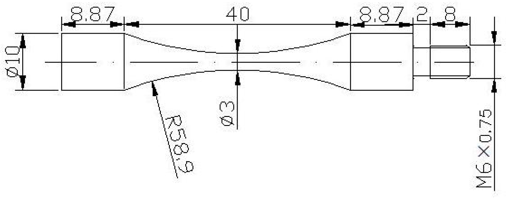
Figure 3.
Cycle strain-life of TC21 titanium alloy.

Figure 4.
LCF surface damage evolution of TC21 titanium alloy under 1.8% strain range: (a) N = 0 cycles; (b) N = 90 cycles (5%); (c) N = 180 cycles (10%); (d) N = 360 cycles (20%).
Figure 4.
LCF surface damage evolution of TC21 titanium alloy under 1.8% strain range: (a) N = 0 cycles; (b) N = 90 cycles (5%); (c) N = 180 cycles (10%); (d) N = 360 cycles (20%).

Figure 5.
Fatigue fracture surface of TC21 alloy under 1.8% strain range, N = 1864 cycles: (a) macroscopic morphology; (b) crack initiation morphology; (c) crack initiation morphology; and (d) crack propagation morphology.
Figure 5.
Fatigue fracture surface of TC21 alloy under 1.8% strain range, N = 1864 cycles: (a) macroscopic morphology; (b) crack initiation morphology; (c) crack initiation morphology; and (d) crack propagation morphology.
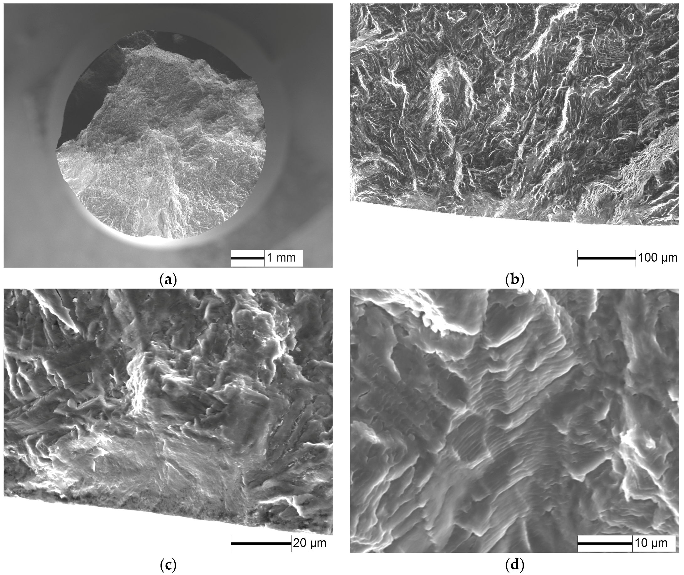
Figure 6.
S-N curves of TC21 for predamaged specimens (Arrows denote the run-out specimens).
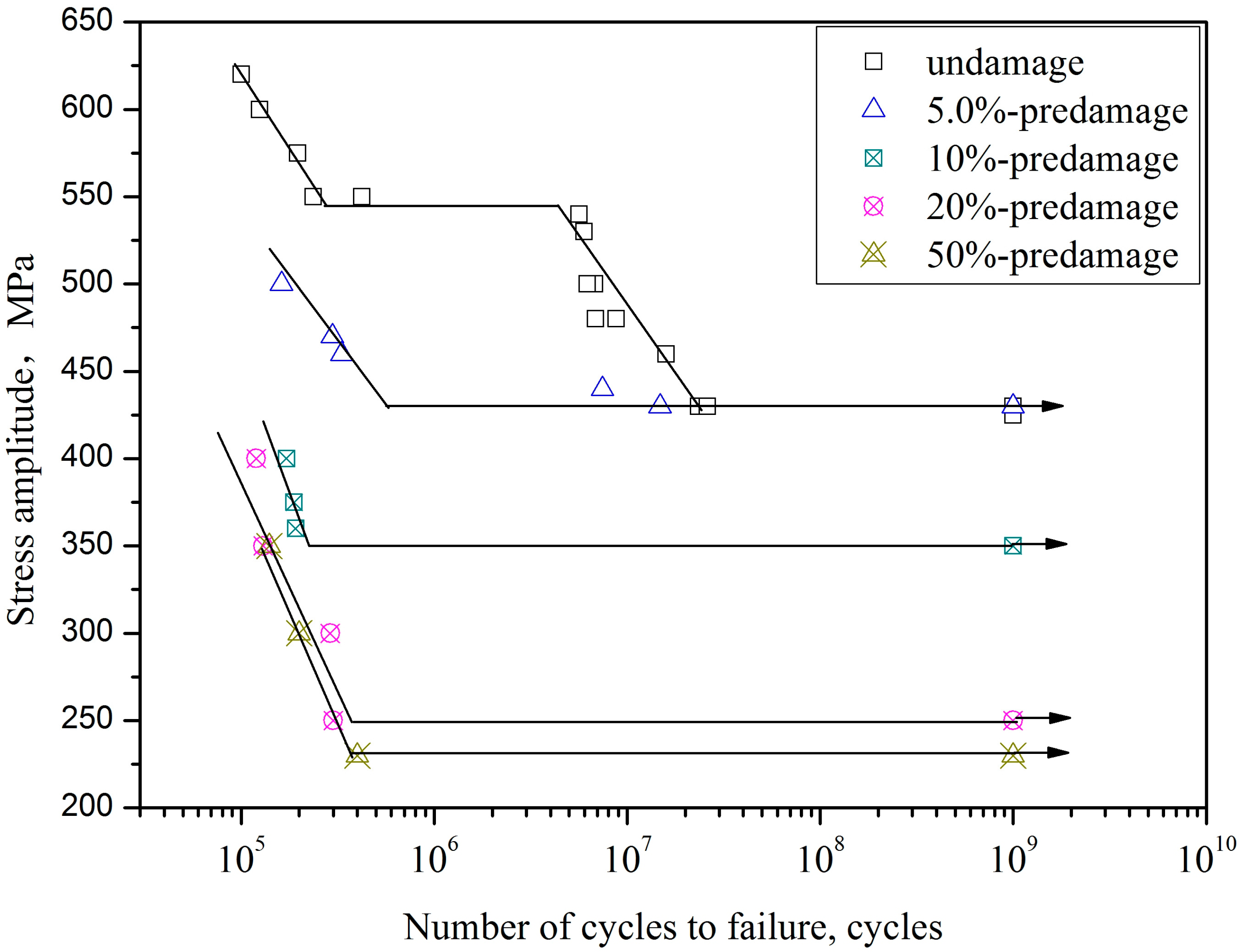
Figure 7.
Fatigue fracture surface of TC21 titanium alloy at σ = 550 MPa and N = 2.37 × 10⁵ cycles: (a) fatigue crack initiation site; and (b) high magnification morphology of crack initiation site.
Figure 7.
Fatigue fracture surface of TC21 titanium alloy at σ = 550 MPa and N = 2.37 × 10⁵ cycles: (a) fatigue crack initiation site; and (b) high magnification morphology of crack initiation site.

Figure 8.
Fatigue fracture surface of TC21 titanium alloy at σ = 480 MPa and N = 6.86 × 10⁶ cycles: (a) fatigue crack initiation site, and (b) high magnification morphology of crack initiation site.
Figure 8.
Fatigue fracture surface of TC21 titanium alloy at σ = 480 MPa and N = 6.86 × 10⁶ cycles: (a) fatigue crack initiation site, and (b) high magnification morphology of crack initiation site.

Figure 9.
Fracture surface for 5% predamaged specimens at σ = 470 MPa and N = 1.27 × 10⁵ cycles: (a) macroscopic morphology; and (b) crack initiation morphology.
Figure 9.
Fracture surface for 5% predamaged specimens at σ = 470 MPa and N = 1.27 × 10⁵ cycles: (a) macroscopic morphology; and (b) crack initiation morphology.

Figure 10.
Fracture surface for 5% predamaged specimens at σ = 430 MPa and N = 1.48 × 10⁷ cycles: (a) macroscopic morphology; and (b) crack initiation morphology.
Figure 10.
Fracture surface for 5% predamaged specimens at σ = 430 MPa and N = 1.48 × 10⁷ cycles: (a) macroscopic morphology; and (b) crack initiation morphology.

Figure 11.
Fracture surface for 10% predamaged specimens at σ = 375 MPa and N = 1.88 × 10⁵ cycles: (a) crack initiation morphology; and (b) crack propagation morphology
Figure 11.
Fracture surface for 10% predamaged specimens at σ = 375 MPa and N = 1.88 × 10⁵ cycles: (a) crack initiation morphology; and (b) crack propagation morphology

Figure 12.
Fracture surface for 20% predamaged specimens at σ = 350 MPa and N = 1.35 × 10⁵ cycles: (a) crack initiation morphology; and (b) crack propagation morphology.
Figure 12.
Fracture surface for 20% predamaged specimens at σ = 350 MPa and N = 1.35 × 10⁵ cycles: (a) crack initiation morphology; and (b) crack propagation morphology.
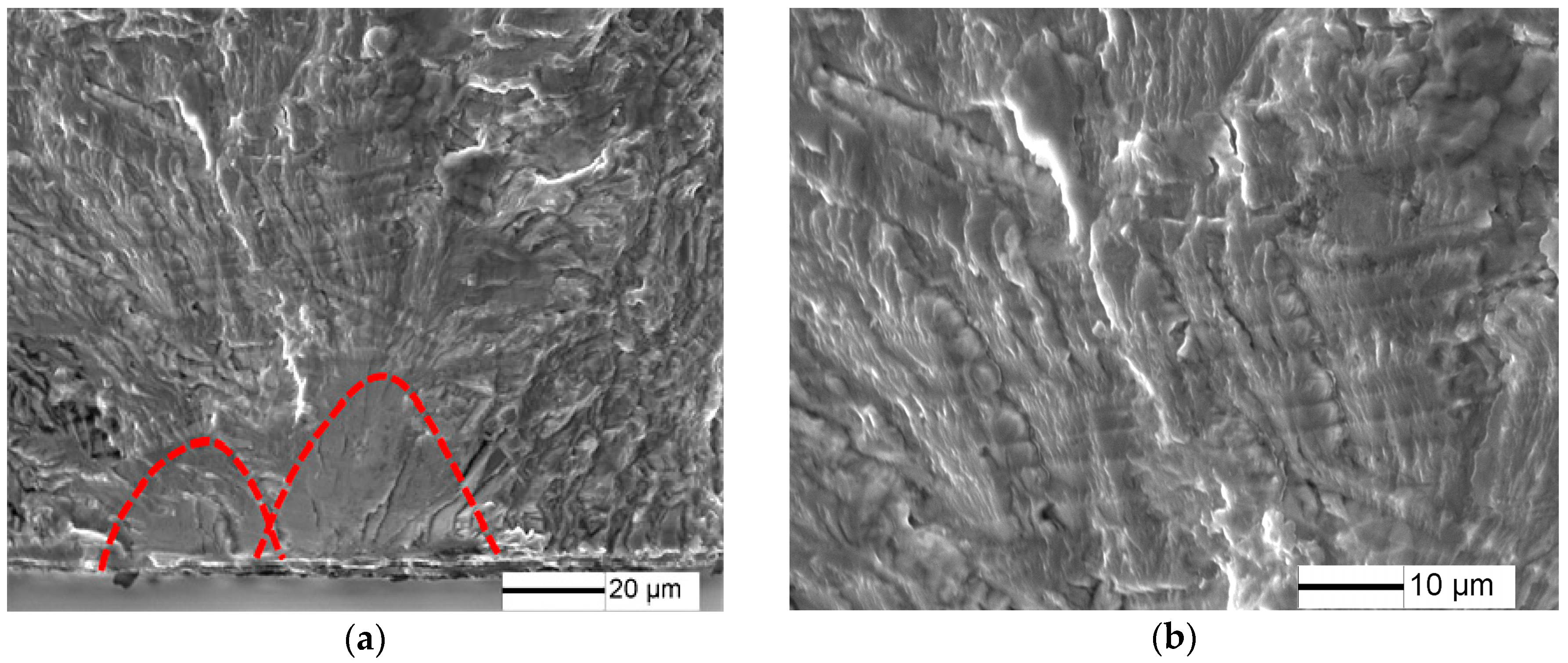
Figure 13.
Fracture surface for 50% predamaged specimens at σ = 230 MPa and N = 4 × 10⁵ cycles: (a) crack initiation morphology; and (b) crack propagation morphology.
Figure 13.
Fracture surface for 50% predamaged specimens at σ = 230 MPa and N = 4 × 10⁵ cycles: (a) crack initiation morphology; and (b) crack propagation morphology.

Figure 14.
Kitagawa–Takahashi diagram of TC21 titanium alloy with predamage.
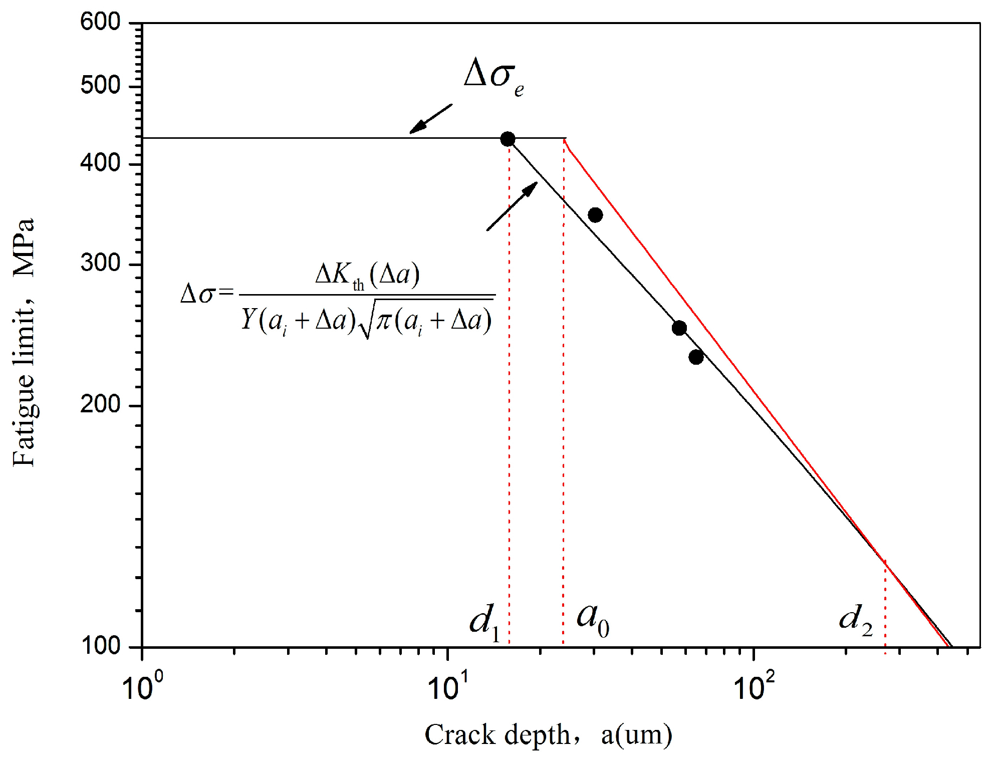
Figure 15.
Morphology of fatigue precracks propagation.
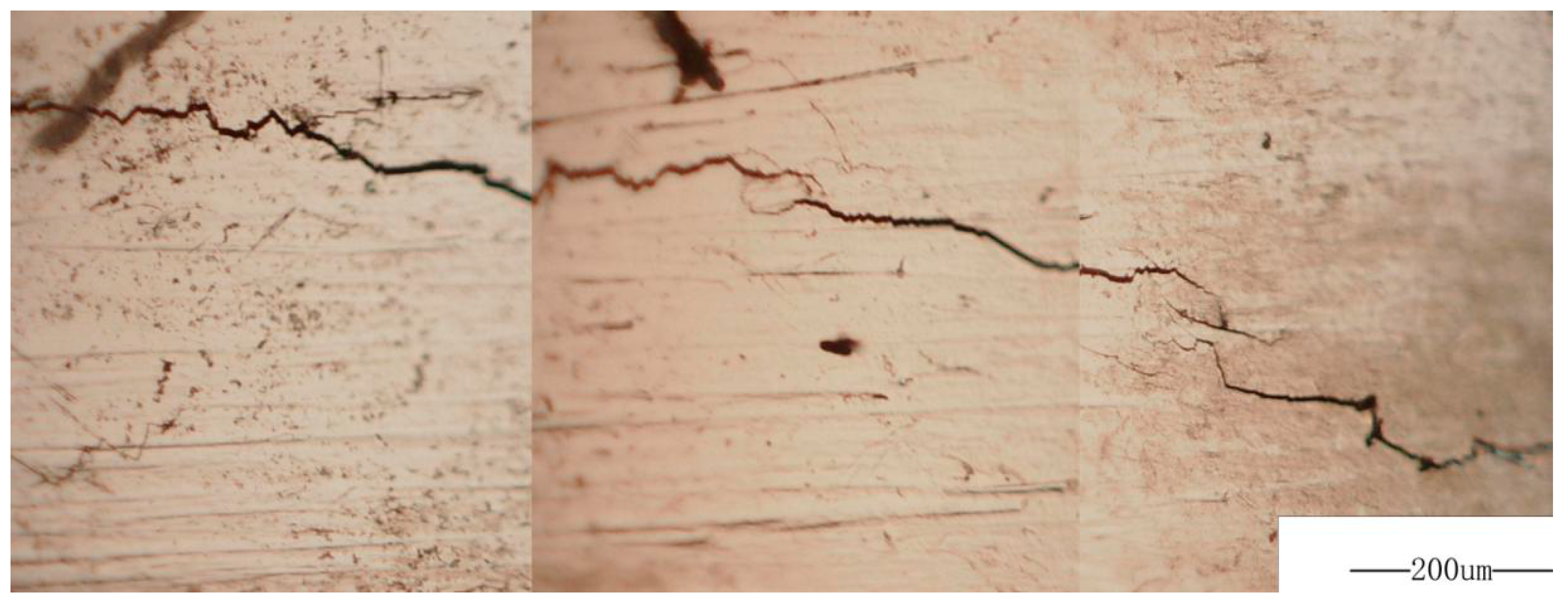
Figure 16.
Relation between the expected precrack propagation rate da/dN and stress intensity factor ∆K.
Figure 16.
Relation between the expected precrack propagation rate da/dN and stress intensity factor ∆K.

Table 1.
Estimation of fatigue crack-propagation life.
| Predamaged Specimens | Stress Amplitude, MPa | N, Cycles | , µm | , µm | Np, Cycles | Np/N, % |
|---|---|---|---|---|---|---|
| 0% | 460 | 1.590 × 10⁷ | 27.56 | 1487 | 8.008 × 10⁴ | 0.50 |
| 5% | 460 | 3.320 × 10⁵ | 27.56 | 1487 | 8.008 × 10⁴ | 24.12 |
| 10% | 350 | 1.920 × 10⁵ | 42.26 | 2427 | 1.440 × 10⁵ | 74.99 |
| 20% | 300 | 2.000 × 10⁵ | 69.06 | 2650 | 1.706 × 10⁵ | 85.30 |
© 2017 by the authors. Licensee MDPI, Basel, Switzerland. This article is an open access article distributed under the terms and conditions of the Creative Commons Attribution (CC BY) license (http://creativecommons.org/licenses/by/4.0/).
Share and Cite
MDPI and ACS Style
Nie, B.; Zhao, Z.; Ouyang, Y.; Chen, D.; Chen, H.; Sun, H.; Liu, S. Effect of Low Cycle Fatigue Predamage on Very High Cycle Fatigue Behavior of TC21 Titanium Alloy. Materials 2017, 10, 1384. https://doi.org/10.3390/ma10121384
AMA Style
Nie B, Zhao Z, Ouyang Y, Chen D, Chen H, Sun H, Liu S. Effect of Low Cycle Fatigue Predamage on Very High Cycle Fatigue Behavior of TC21 Titanium Alloy. Materials. 2017; 10(12):1384. https://doi.org/10.3390/ma10121384
Chicago/Turabian StyleNie, Baohua, Zihua Zhao, Yongzhong Ouyang, Dongchu Chen, Hong Chen, Haibo Sun, and Shu Liu. 2017. "Effect of Low Cycle Fatigue Predamage on Very High Cycle Fatigue Behavior of TC21 Titanium Alloy" Materials 10, no. 12: 1384. https://doi.org/10.3390/ma10121384
Note that from the first issue of 2016, this journal uses article numbers instead of page numbers. See further details here.