Characterization and Bone Response of Carbonate-Containing Apatite-Coated Titanium Implants Using an Aqueous Spray Coating


Abstract
:1. Introduction
2. Results
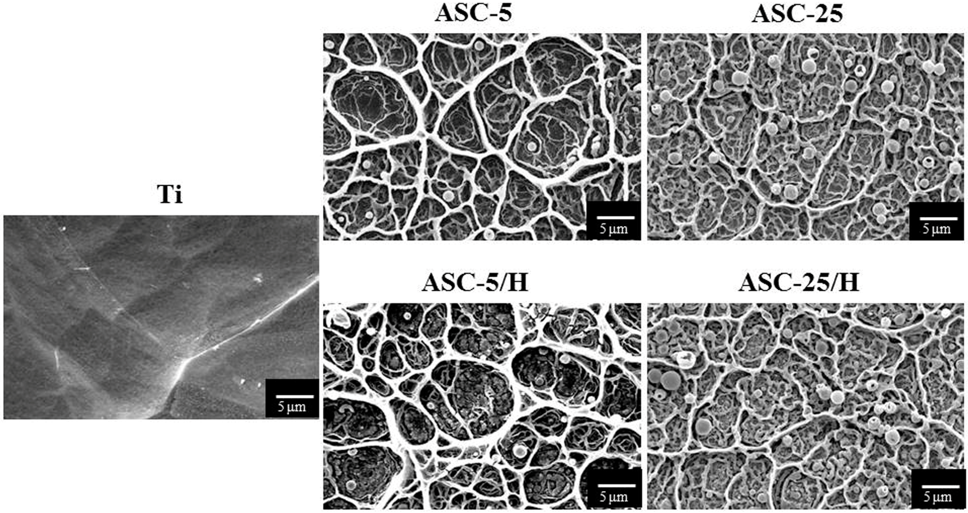
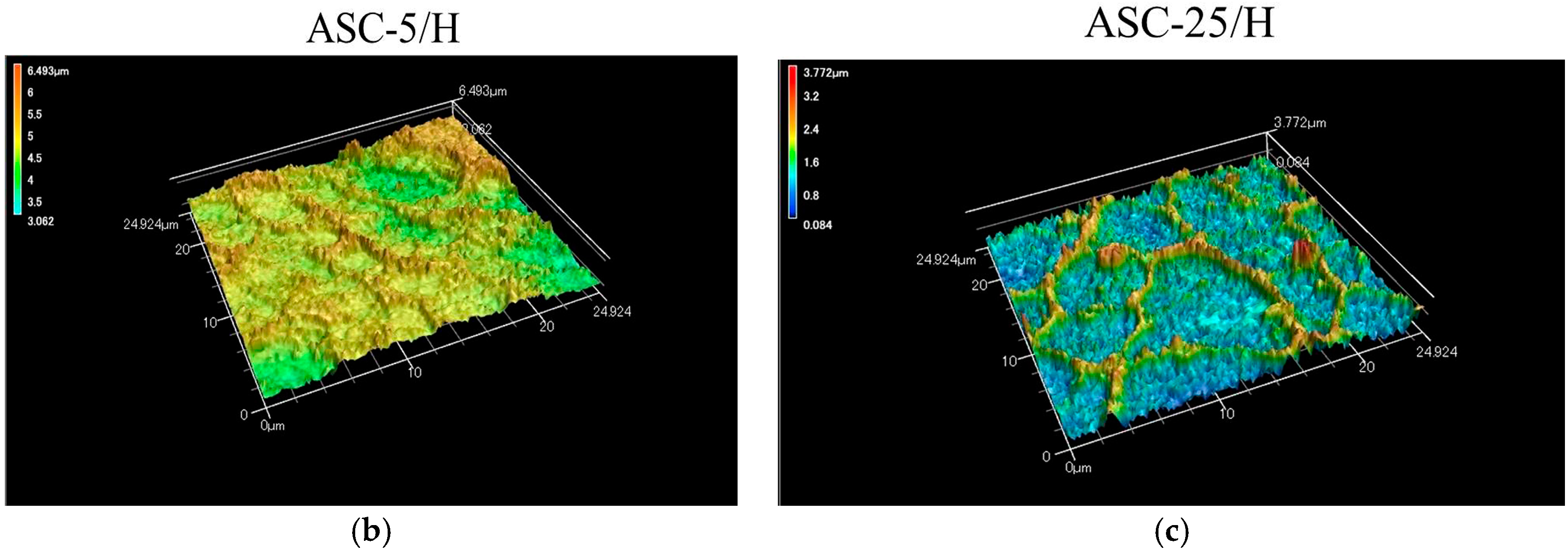
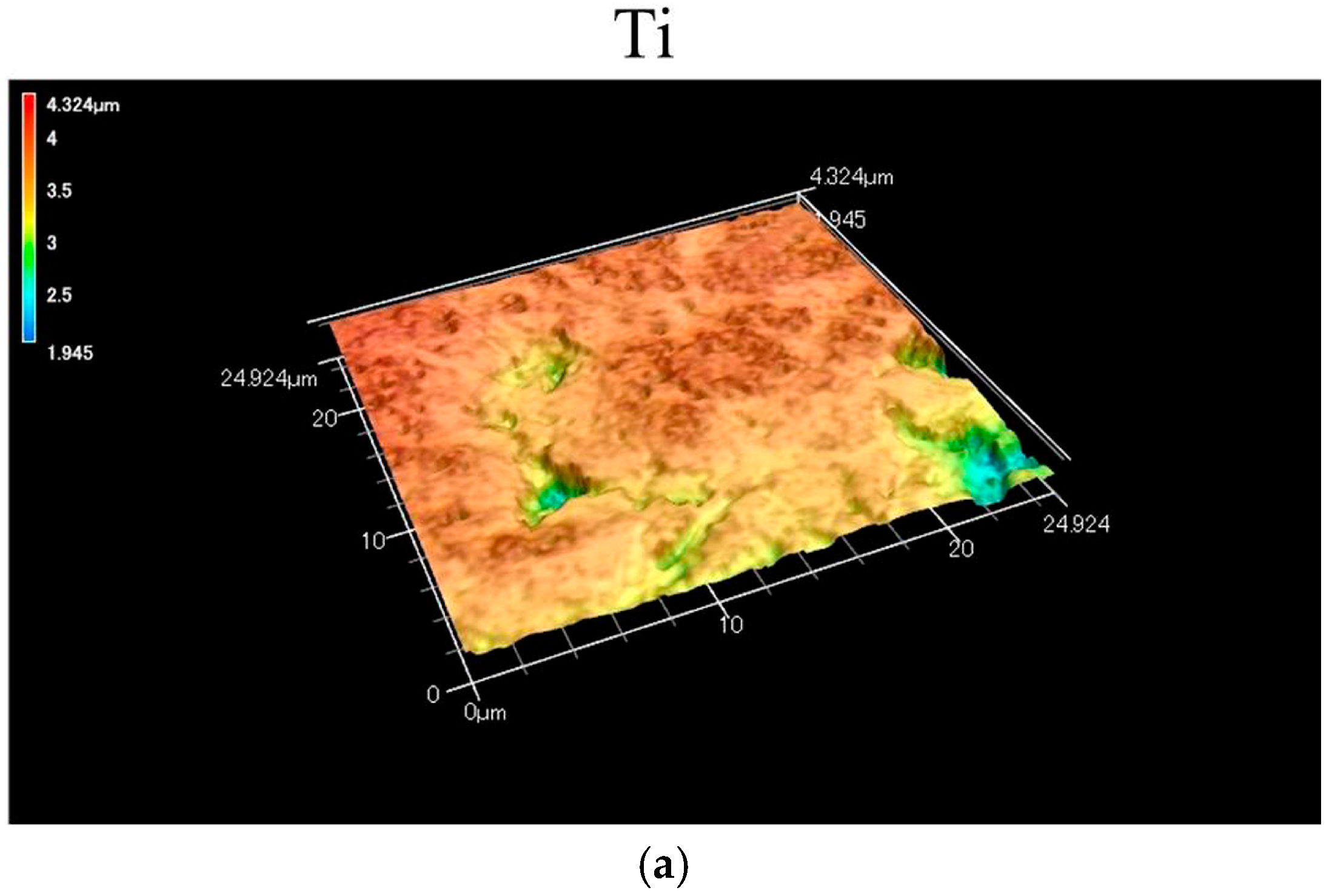
2.1. Morphology and Surface Roughness
2.2. Adhesiveness of CA Coating
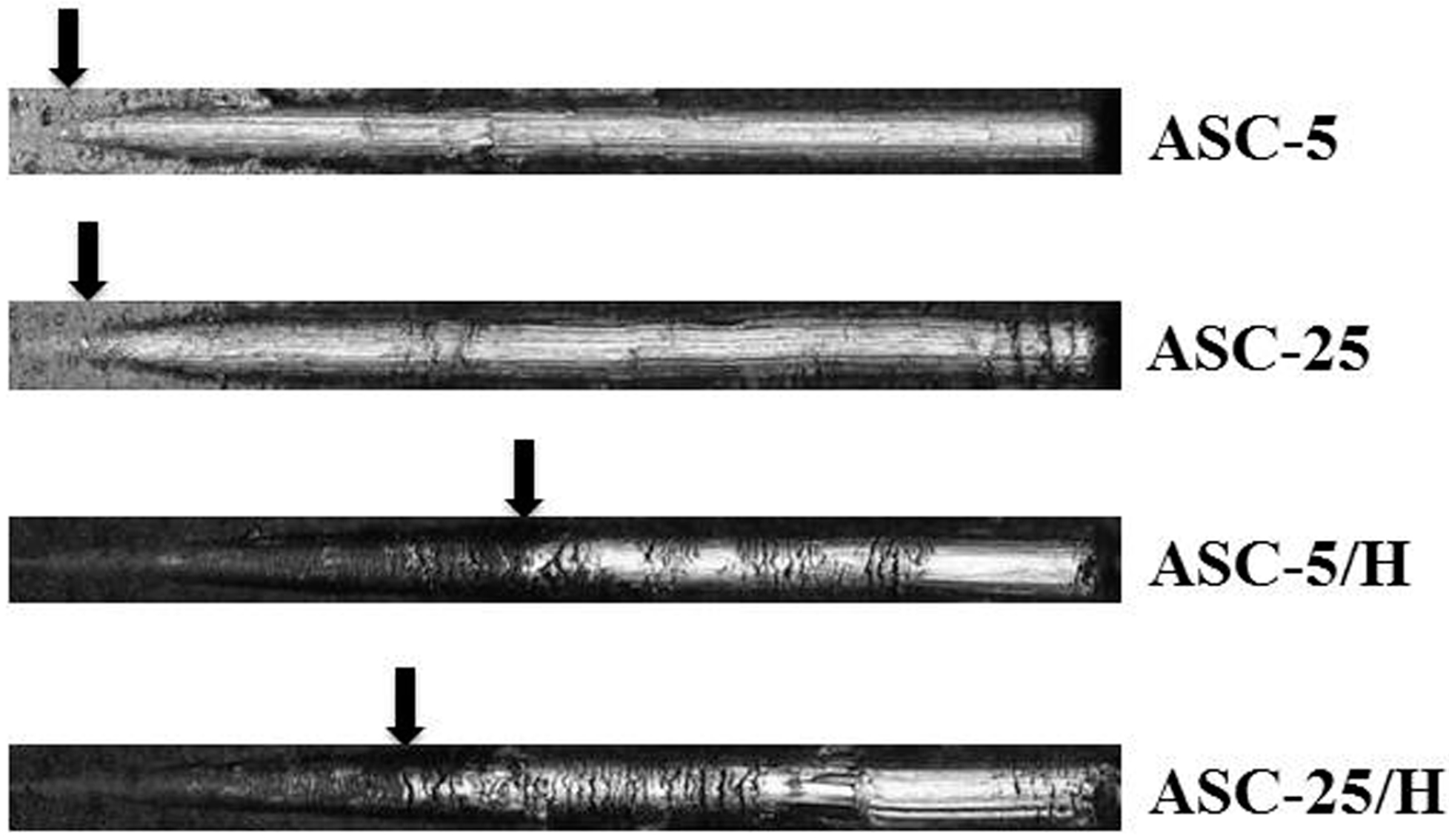
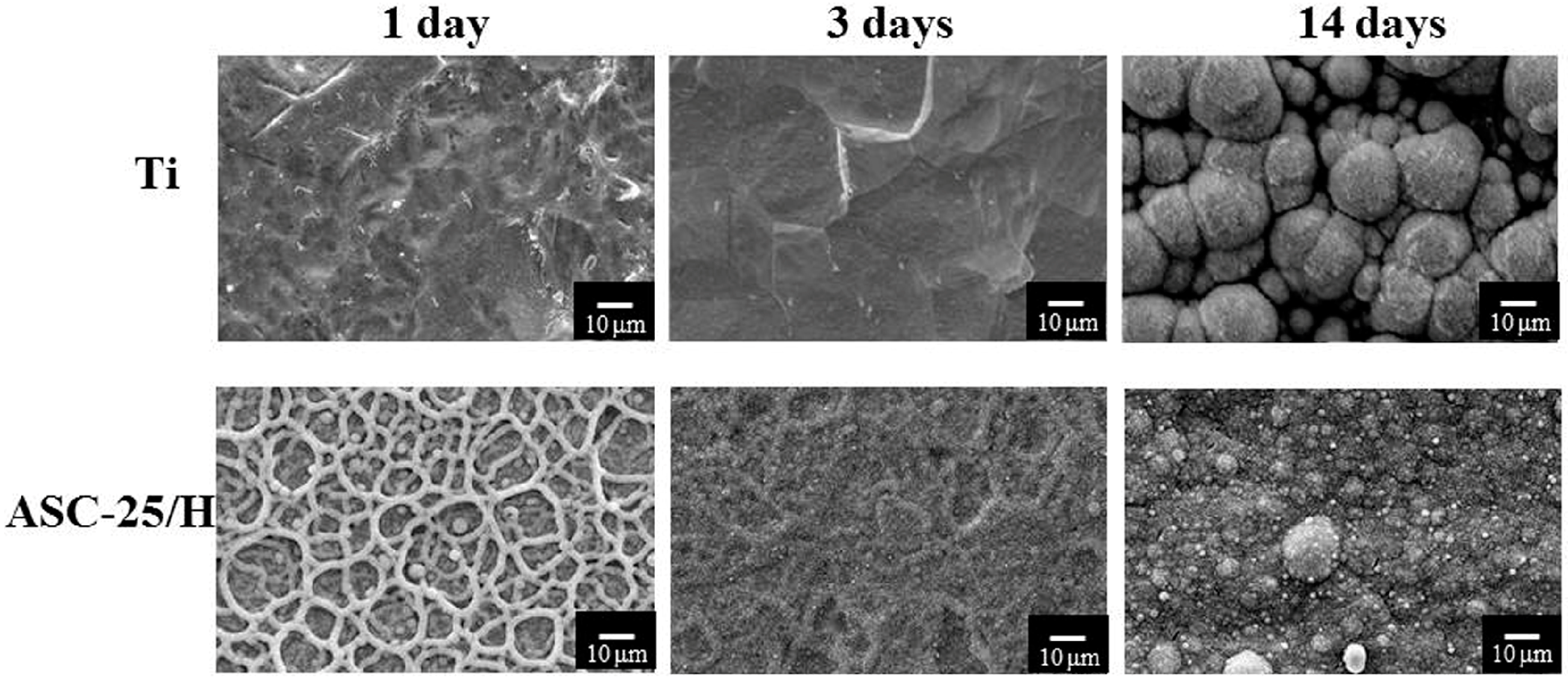
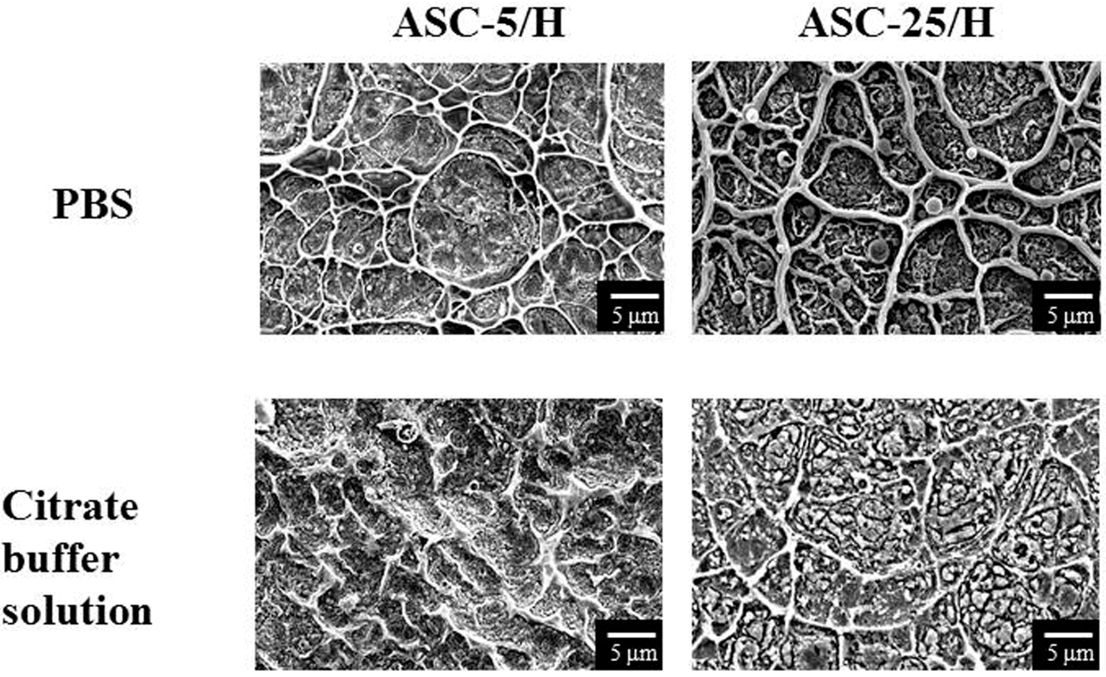
2.3. Durability
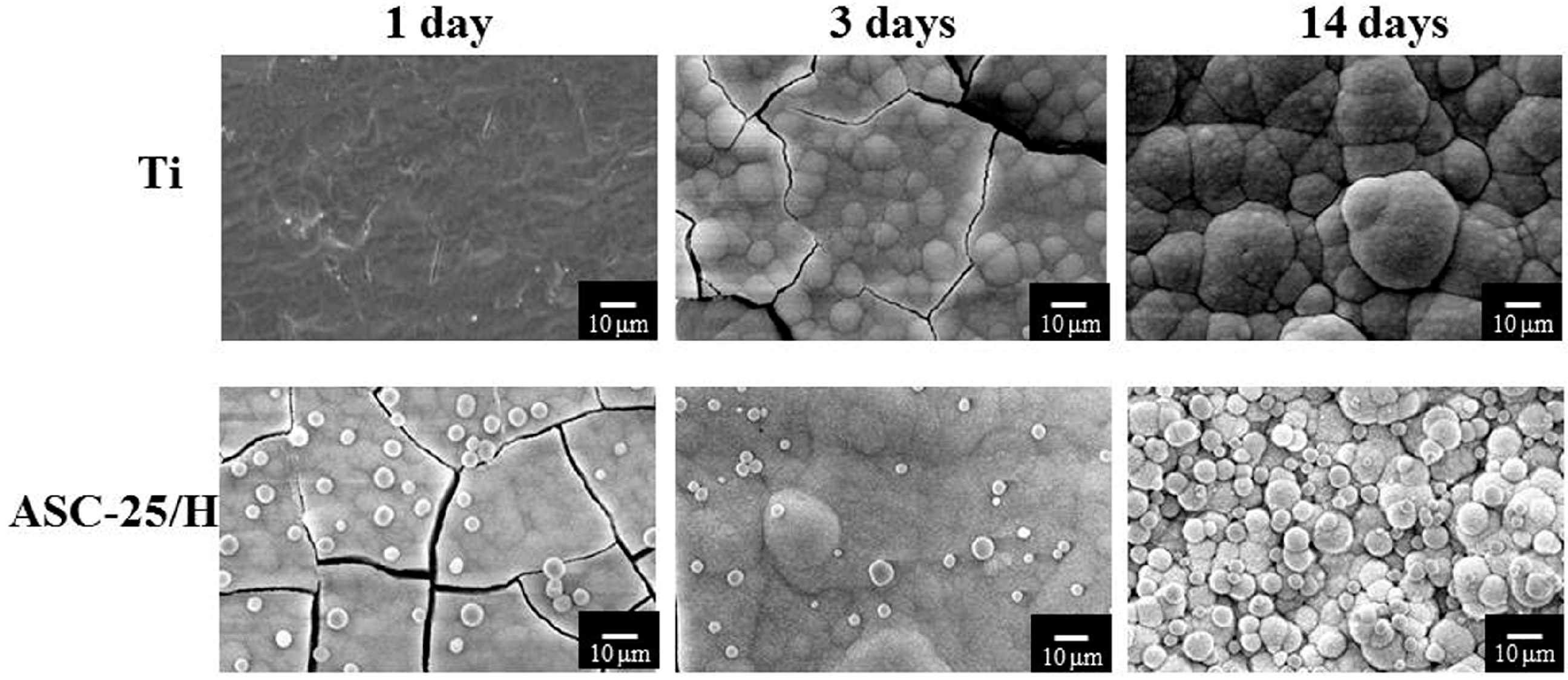
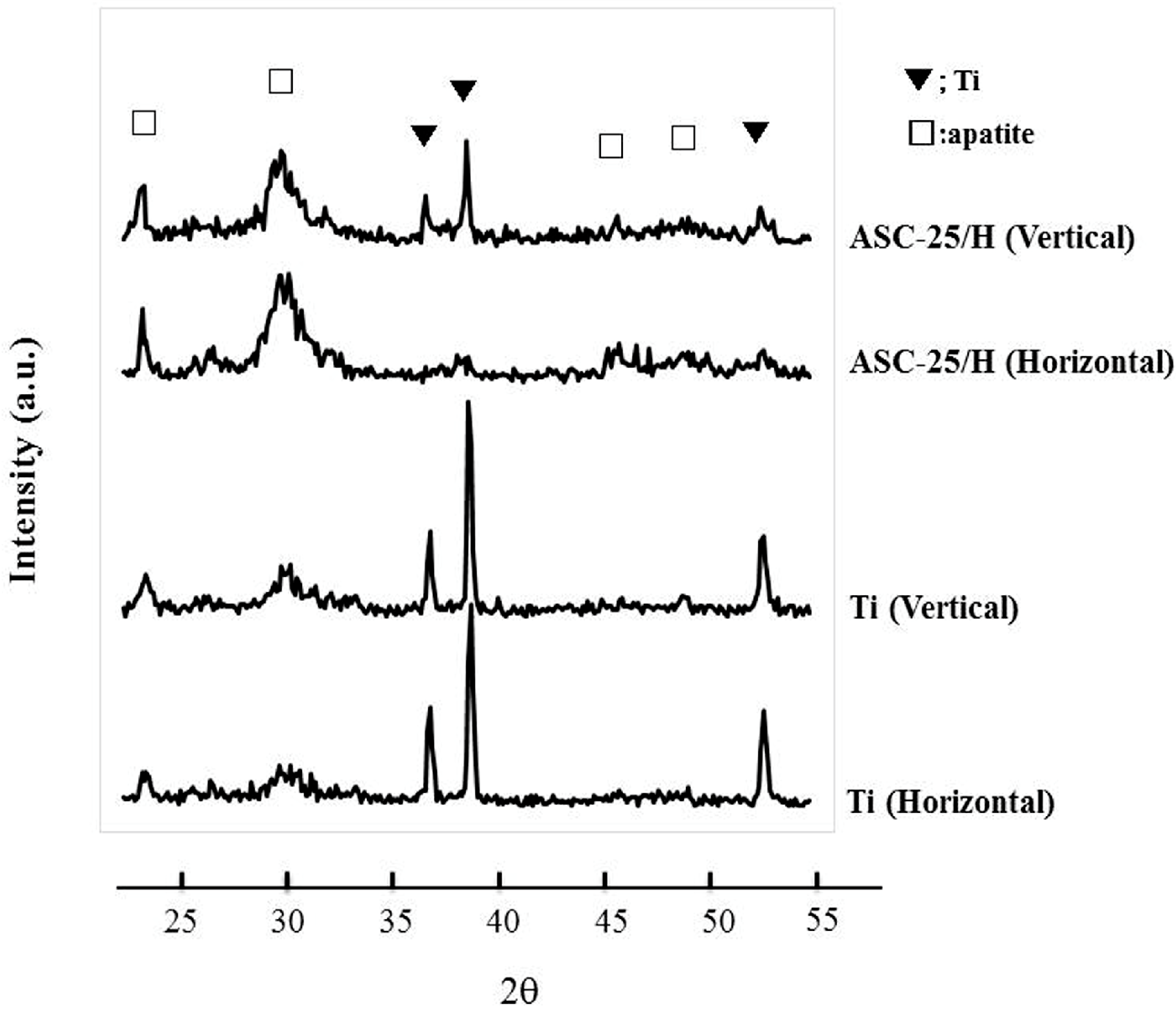
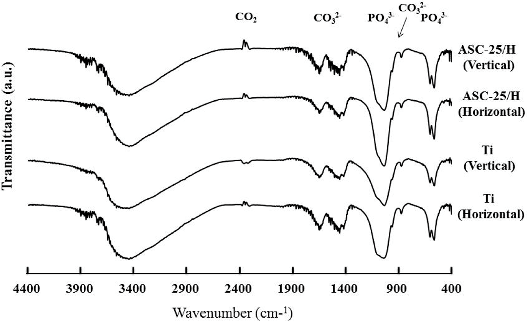
2.4. SBF Immersion
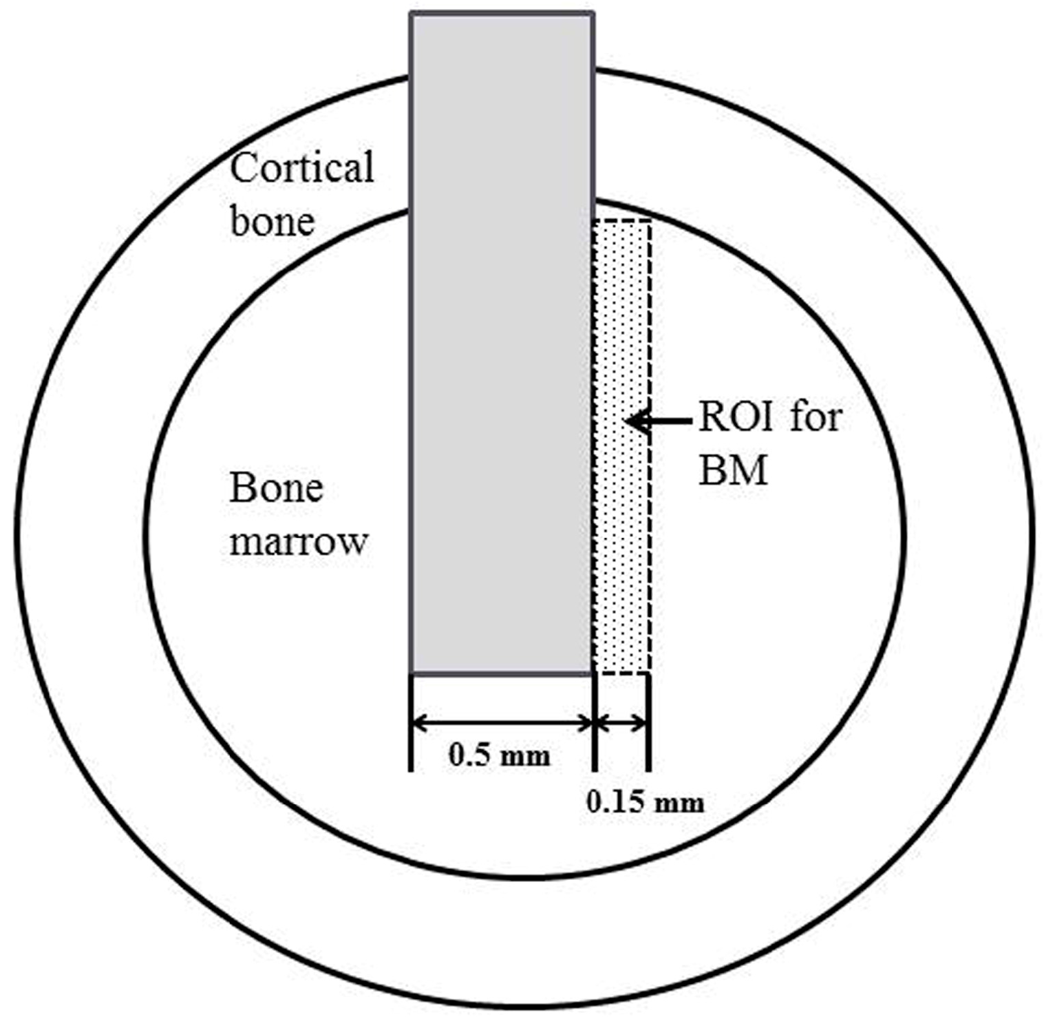
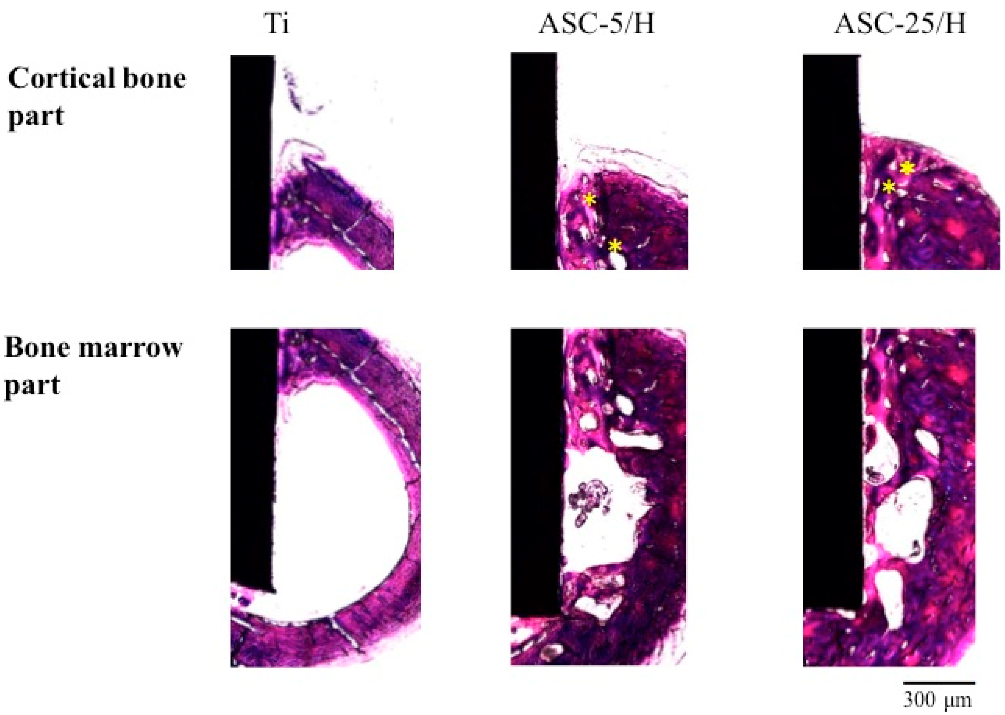
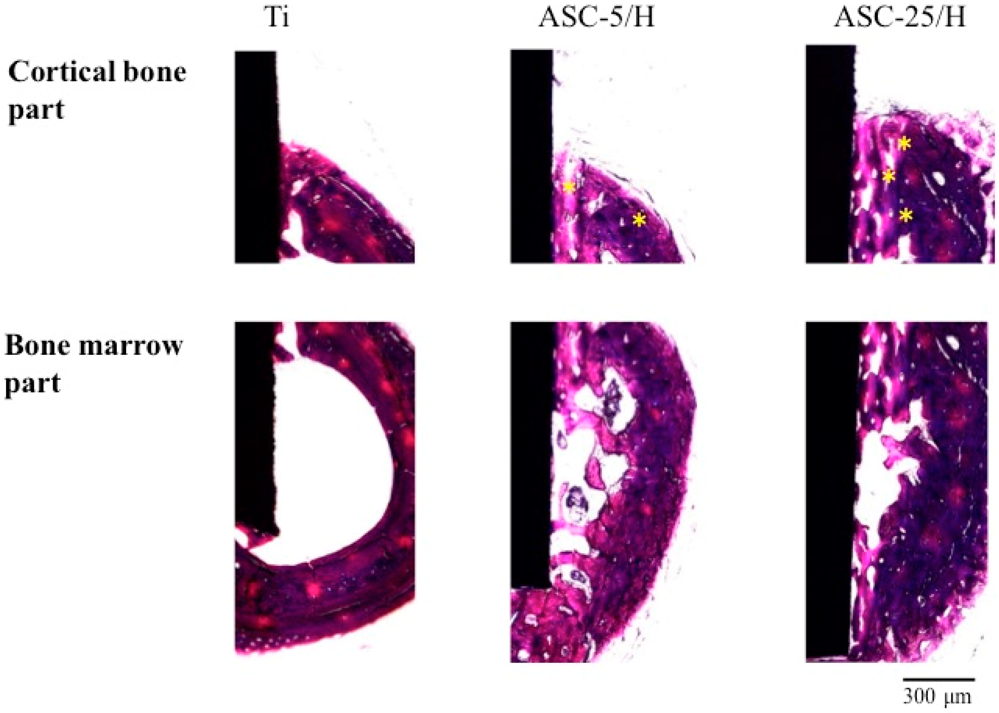
2.5. Histological and Histomorphometrical Evaluation
3. Discussion
4. Materials and Methods
4.1. Experiment Specimens
4.2. Preparation of ASC Solution and Spray Coating
4.3. Surface Morphologies and Surface Roughness of CA Film
4.4. Adhesiveness of CA Films
4.5. Durability of CA Coating
4.6. SBF Immersion
4.7. Animal Experimentation
4.8. Histological and Histomorphometrical Evaluation
4.9. Implant Push-In Test
4.10. Statistical Analysis
5. Conclusions
Acknowledgments
Author Contributions
Conflicts of Interest
References
- Hanawa, T. Materials for metallic stents. J. Artif. Organs 2009, 12, 73–79. [Google Scholar] [CrossRef] [PubMed]
- Ananth, H.; Kundapur, V.; Mohammed, H.S.; Anand, M.; Amarnath, G.S.; Mankar, S.A. Review on Biomaterials in Dental Implantology. Int. J. Biomed. Sci. 2015, 11, 113–120. [Google Scholar] [PubMed]
- Brånemark, P.I. Osseointegration and its experimental background. J. Prosthet. Dent. 1983, 50, 399–410. [Google Scholar] [CrossRef]
- De Jonge, L.T.; Leeuwenburgh, S.C.; Wolke, J.G.; Jansen, J.A. Organic-inorganic surface modifications for titanium implant surfaces. Pharm. Res. 2008, 25, 2357–2369. [Google Scholar] [CrossRef] [PubMed]
- Wennerberg, A.; Albrektsson, T. Structural influence from calcium phosphate coating and its possible effect on enhanced bone integration. Acta Odontol. Scand. 2009, 67, 333–340. [Google Scholar] [CrossRef] [PubMed]
- Graziani, G.; Bianchi, M.; Sassoni, E.; Russo, A.; Marcacci, M. Ion-substituted calcium phosphate coatings deposited by plasma-assisted techniques: A review. Mater. Sci. Eng. C Mater. Biol. Appl. 2017, 74, 219–229. [Google Scholar] [CrossRef] [PubMed]
- Wen, J.; Leng, Y.; Chen, J.; Zhang, C. Chemical gradient in plasma-sprayed HA coatings. Biomaterials 2000, 21, 1339–1343. [Google Scholar] [CrossRef]
- Otsuka, Y.; Kojima, D.; Mutoh, Y. Prediction of cyclic delamination lives of plasma-sprayed hydroxyapatite coating on Ti-6Al-4V substrates with considering wear and dissolutions. J. Mech. Behav. Biomed. Mater. 2016, 64, 113–124. [Google Scholar] [CrossRef] [PubMed]
- Ramires, P.A.; Wennerberg, A.; Johansson, C.B.; Cosentino, F.; Tundo, S.; Milella, E. Biological behavior of sol-gel coated dental implants. J. Mater. Sci. Mater. Med. 2003, 14, 539–545. [Google Scholar] [CrossRef] [PubMed]
- Li, X.; Li, Y.; Liao, Y.; Li, J.; Zhang, L.; Hu, J. The effect of magnesium-incorporated hydroxyapatite coating on titanium implant fixation in ovariectomized rats. Int. J. Oral Maxillofac. Implants 2014, 29, 196–202. [Google Scholar] [CrossRef] [PubMed]
- Hayakawa, T.; Yoshinari, M.; Kiba, H.; Yamamoto, H.; Nemoto, K.; Jansen, J.A. Trabecular bone response to surface roughened and calcium phosphate (Ca-P) coated titanium implants. Biomaterials 2002, 23, 1025–1031. [Google Scholar] [CrossRef]
- Wan, T.; Aoki, H.; Hikawa, J.; Lee, J.H. RF-magnetron sputtering technique for producing hydroxyapatite coating film on various substrates. Biomed. Mater. Eng. 2007, 17, 291–297. [Google Scholar] [PubMed]
- Mróz, W. Physics of deposition of hydroxyapatite layers by the pulsed laser deposition method. In Functional Properties of Nanostructured Materials; Kassing, R., Petkov, P., Kulisch, W., Popov, C., Eds.; NATO Science Series II: Mathematics, Physics and Chemistry; Springer: Dordrecht, The Netherlands, 2006; Volume 223, pp. 183–196. [Google Scholar]
- Leeuwenburgh, S.; Wolke, J.; Schoonman, J.; Jansen, J. Electrostatic spray deposition (ESD) of calcium phosphate coatings. J. Biomed. Mater. Res. A. 2003, 66, 330–334. [Google Scholar] [CrossRef] [PubMed]
- Siebers, M.C.; Walboomers, X.F.; Leeuwenburgh, S.C.; Wolke, J.G.; Jansen, J.A. Electrostatic spray deposition (ESD) of calcium phosphate coatings, an in vitro study with osteoblast-like cells. Biomaterials 2004, 25, 2019–2027. [Google Scholar] [CrossRef] [PubMed]
- Rey, C.; Combes, C.; Drouet, C.; Glimcher, M.J. Bone mineral: Update on chemical composition and structure. Osteoporos. Int. 2009, 20, 1013–1021. [Google Scholar] [CrossRef] [PubMed]
- Van Oirschot, B.A.; Eman, R.M.; Habibovic, P.; Leeuwenburgh, S.C.; Tahmasebi, Z.; Weinans, H.; Alblas, J.; Meijer, G.J.; Jansen, J.A.; van den Beucken, J.J. Osteophilic properties of bone implant surface modifications in a cassette model on a decorticated goat spinal transverse process. Acta Biomater. 2016, 37, 195–205. [Google Scholar] [CrossRef] [PubMed]
- Mistry, S.; Roy, R.; Kundu, B.; Datta, S.; Kumar, M.; Chanda, A.; Kundu, D. Clinical Outcome of Hydroxyapatite Coated, Bioactive Glass Coated, and Machined Ti6Al4V Threaded Dental Implant in Human Jaws: A Short-Term Comparative Study. Implant Dent. 2016, 25, 252–260. [Google Scholar] [CrossRef] [PubMed]
- Van Oirschot, B.A.; Bronkhorst, E.M.; van den Beucken, J.J.; Meijer, G.J.; Jansen, J.A.; Junker, R. A systematic review on the long-term success of calcium phosphate plasma-spray-coated dental implants. Odontology 2016, 104, 347–356. [Google Scholar] [CrossRef] [PubMed]
- Ball, M.D.; Downes, S.; Scotchford, C.A.; Antonov, E.N.; Bagratashvili, V.N.; Popov, V.K.; Lo, W.J.; Grant, D.M.; Howdle, S.M. Osteoblast growth on titanium foils coated with hydroxyapatite by pulsed laser ablation. Biomaterials 2001, 22, 337–347. [Google Scholar] [CrossRef]
- Madi, M.; Zakaria, O.; Noritake, K.; Fuji, M.; Kasugai, S. Peri-implantitis progression around thin sputtered hydroxyapatite-coated implants: Clinical and radiographic evaluation in dogs. Int. J. Oral Maxillofac. Implant. 2013, 28, 701–709. [Google Scholar] [CrossRef] [PubMed]
- Cuijpers, V.M.; Alghamdi, H.S.; Van Dijk, N.W.; Jaroszewicz, J.; Walboomers, X.F.; Jansen, J.A. Osteogenesis around CaP-coated titanium implants visualized using 3D histology and micro-computed tomography. J. Biomed. Mater. Res. A 2015, 103, 3463–3473. [Google Scholar] [CrossRef] [PubMed]
- Takahashi, K.; Hayakawa, T.; Yoshinari, M.; Hara, H.; Mochizuki, C.; Sato, M.; Nemoto, K. Molecular precursor method for thin calcium phosphate coating on titanium. Thin Solid Films 2005, 484, 1–9. [Google Scholar] [CrossRef]
- Takahashi, K.; Hayakawa, T.; Yoshinari, M.; Hara, H.; Mochizuki, C.; Sato, M.; Nemoto, K. Properties of hydroxyapatite thin film prepared by molecular precursor method. J. Dent. Mater. 2005, 24, 39–46. [Google Scholar]
- Hayakawa, T.; Takahashi, K.; Yoshinari, M.; Okada, H.; Yamamoto, H.; Sato, M.; Nemoto, K. Trabecular bone response to titanium implants with a thin carbonate-containing apatite coating applied using the molecular precursor method. Int. J. Oral Maxillofac. Implants 2006, 21, 851–858. [Google Scholar] [PubMed]
- Kaneko, H.; Sasaki, H.; Honma, S.; Hayakawa, T.; Sato, M.; Yajima, Y.; Yoshinari, M. Influence of thin carbonate-containing apatite coating with molecular precursor method to zirconia on osteoblast-like cell response. Dent. Mater. J. 2014, 33, 39–47. [Google Scholar] [CrossRef] [PubMed]
- Hirota, M.; Hayakawa, T.; Ohkubo, C.; Sato, M.; Hara, H.; Toyama, T.; Tanaka, Y. Bone responses to zirconia implants with a thin carbonate-containing hydroxyapatite coating using a molecular precursor method. J. Biomed. Mater. Res. B Appl. Biomater. 2014, 102, 1277–1288. [Google Scholar] [CrossRef] [PubMed]
- Mochizuki, C.; Hara, H.; Takano, I.; Hayakawa, T.; Sato, M. Application of carbonated apatite coating on a Ti substrate by aqueous spray method. Mater. Sci. Eng. C Mater. Biol. Appl. 2013, 33, 951–958. [Google Scholar] [CrossRef] [PubMed]
- Mochizuki, C.; Hara, H.; Oya, K.; Aoki, S.; Hayakawa, T.; Fujie, H.; Sato, M. Behaviors of MC3T3-E1 cells on carbonated apatite films, with a characteristic network structure, fabricated on a titanium plate by aqueous spray coating. Mater. Sci. Eng. C Mater. Biol. 2014, 39, 245–252. [Google Scholar] [CrossRef] [PubMed]
- Hirota, M.; Mochizuki, C.; Sato, M.; Hayakawa, T. Influence of heating conditions for formation of a thin apatite film on zirconia using a molecular precursor method. Coatings 2017, 7, 69. [Google Scholar] [CrossRef]
- Hanawa, T.; Ota, M. Calcium phosphate naturally formed on titanium in electrolyte solution. Biomaterials 1991, 12, 767–774. [Google Scholar] [CrossRef]
- Suzuki, H.; Yagi, R.; Waki, T.; Wada, T.; Ohkubo, C.; Hayakawa, T. Study of apatite deposition in a simulated body fluid immersion experiment. J. Oral Tissue Eng. 2016, 14, 9–14. [Google Scholar]
- Kokubo, T.; Takadama, H. How useful is SBF in predicting in vivo bone bioactivity? Biomaterials 2006, 27, 2907–2915. [Google Scholar] [CrossRef] [PubMed]
- Wennerberg, A.; Albrektsson, T. Effects of titanium surface topography on bone integration: A systematic review. Clin. Oral Implants Res. 2009, 20 (Suppl. S4), 172–184. [Google Scholar] [CrossRef] [PubMed]
- Albrektsson, T.; Eriksson, A.R.; Friberg, B.; Lekholm, U.; Lindahl, L.; Nevins, M.; Oikarinen, V.; Roos, J.; Sennerby, L.; Astrand, P. Histologic investigations on 33 retrieved Nobelpharma implants. Clin. Mater. 1993, 12, 1–9. [Google Scholar] [CrossRef]
- Seong, W.J.; Kim, U.K.; Swift, J.Q.; Heo, Y.C.; Hodges, J.S.; Ko, C.C. Elastic properties and apparent density of human edentulous maxilla and mandible. Int. J. Oral Maxillofac. Surg. 2009, 38, 1088–1093. [Google Scholar] [CrossRef] [PubMed]
- Nkenke, E.; Hahn, M.; Weinzieri, K.; Radespiel-Tröger, M.; Neukam, F.W.; Engelke, K. Implant stability and histomorphometry: A correlation study in human cadavers using stepped cylinder implants. Clin. Oral Implants Res. 2003, 14, 601–609. [Google Scholar] [CrossRef] [PubMed]
- Hayakawa, T.; Yoshinari, M.; Nemoto, K.; Wolke, J.G.C.; Jansen, J.A. Effect of surface roughness and calcium phosphate coating on the implant/bone response. Clin. Oral Implants Res. 2000, 11, 296–304. [Google Scholar] [CrossRef] [PubMed]
- Siebers, M.C.; Wolke, J.G.; Walboomers, X.F.; Leeuwenburgh, S.C.; Jansen, J.A. In vivo evaluation of the trabecular bone behavior to porous electrostatic spray deposition-derived calcium phosphate coatings. Clin. Oral Implants Res. 2007, 18, 354–361. [Google Scholar] [CrossRef] [PubMed]
- Lin, A.; Wang, C.J.; Kelly, J.; Gubbi, P.; Nishimura, I. The role of titanium implant surface modification with hydroxyapatite nanoparticles in progressive early bone-implant fixation in vivo. Int. J. Oral Maxillofac. Implants 2009, 24, 808–816. [Google Scholar] [PubMed]
- Suzuki, T.; Hayakawa, T.; Kawamoto, T.; Gomi, K. Bone response of TGF-β2 immobilized titanium in a rat model. Dent. Mater. J. 2014, 33, 233–241. [Google Scholar] [CrossRef] [PubMed]
- Donath, K.; Breuner, G. A method for the study of undecalcified bones and teeth with attached soft tissues. The Säge-Schliff (sawing and grinding) technique. J. Oral Pathol. 1982, 11, 318–326. [Google Scholar] [CrossRef] [PubMed]


| Specimen | Sa (μm) | Sdr (μm) |
|---|---|---|
| Ti | 0.17 (0.01) a | 0.17 (0.09) d |
| ASC-5/H | 0.31 (0.04) b | 4.34 (0.35) e |
| ASC-25/H | 0.46 (0.06) c | 16.76 (2.60) f |
| Specimen | Lc Value (mN) |
|---|---|
| ASC-5 | 4.1 (0.5) a |
| ASC-25 | 6.8 (0.3) a |
| ASC-5/H | 36.1 (10.5) b |
| ASC-25/H | 23.8 (4.7) b |
| Specimen | Cortical Bone Part | Bone Marrow Part | ||
|---|---|---|---|---|
| Two Weeks | Four Weeks | Two Weeks | Four Weeks | |
| Ti | 29.7 (14.8) a,A | 46.1 (7.6) b,A | 22.6 (6.9) e,F | 27.6 (14.8) g,F |
| ASC-5/H | 41.4 (11.7) a,B | 78.7 (4.8) c,C | 34.9 (12.3) e,f,G | 72.3 (18.6) h,H |
| ASC-25/H | 46.1 (10.0) a,D | 64.1 (8.2) d,E | 46.5 (9.4) f,I | 63.8 (10.2) h,J |
| Specimen | Two Weeks | Four Weeks |
|---|---|---|
| Ti | 21.0 (1.6) a,A | 21.1 (6.5) c,A |
| ASC-5/H | 31.8 (4.0) b,B | 41.6 (11.2) d,B |
| ASC-25/H | 35.3 (7.6) b,C | 62.4 (4.3) e,D |
| Specimen | Load (N) |
|---|---|
| Ti | 3.3 (0.2) a |
| ASC-5/H | 23.4 (5.5) b |
| ASC-25/H | 20.1 (0.7) b |
© 2017 by the authors. Licensee MDPI, Basel, Switzerland. This article is an open access article distributed under the terms and conditions of the Creative Commons Attribution (CC BY) license (http://creativecommons.org/licenses/by/4.0/).
Share and Cite
Yagi, R.; Mochizuki, C.; Sato, M.; Toyama, T.; Hirota, M.; Hayakawa, T.; Ohkubo, C. Characterization and Bone Response of Carbonate-Containing Apatite-Coated Titanium Implants Using an Aqueous Spray Coating. Materials 2017, 10, 1416. https://doi.org/10.3390/ma10121416
Yagi R, Mochizuki C, Sato M, Toyama T, Hirota M, Hayakawa T, Ohkubo C. Characterization and Bone Response of Carbonate-Containing Apatite-Coated Titanium Implants Using an Aqueous Spray Coating. Materials. 2017; 10(12):1416. https://doi.org/10.3390/ma10121416
Chicago/Turabian StyleYagi, Ryo, Chihiro Mochizuki, Mitsunobu Sato, Takeshi Toyama, Masatsugu Hirota, Tohru Hayakawa, and Chikahiro Ohkubo. 2017. "Characterization and Bone Response of Carbonate-Containing Apatite-Coated Titanium Implants Using an Aqueous Spray Coating" Materials 10, no. 12: 1416. https://doi.org/10.3390/ma10121416