LaAlO3:Mn4+ as Near-Infrared Emitting Persistent Luminescence Phosphor for Medical Imaging: A Charge Compensation Study


LumiLab, Department of Solid State Sciences, Ghent University, Krijgslaan 281-S1, 9000 Ghent, Belgium
*
Author to whom correspondence should be addressed.
Materials 2017, 10(12), 1422; https://doi.org/10.3390/ma10121422
Submission received: 10 November 2017
/
Revised: 5 December 2017
/
Accepted: 9 December 2017
/
Published: 12 December 2017
(This article belongs to the Special Issue State-of-the-Art Materials Science in Belgium 2017)
Abstract
:Mn4+-activated phosphors are emerging as a novel class of deep red/near-infrared emitting persistent luminescence materials for medical imaging as a promising alternative to Cr3+-doped nanomaterials. Currently, it remains a challenge to improve the afterglow and photoluminescence properties of these phosphors through a traditional high-temperature solid-state reaction method in air. Herein we propose a charge compensation strategy for enhancing the photoluminescence and afterglow performance of Mn4+-activated LaAlO3 phosphors. LaAlO3:Mn4+ (LAO:Mn4+) was synthesized by high-temperature solid-state reaction in air. The charge compensation strategies for LaAlO3:Mn4+ phosphors were systematically discussed. Interestingly, Cl−/Na+/Ca2+/Sr2+/Ba2+/Ge4+ co-dopants were all found to be beneficial for enhancing LaAlO3:Mn4+ luminescence and afterglow intensity. This strategy shows great promise and opens up new avenues for the exploration of more promising near-infrared emitting long persistent phosphors for medical imaging.

1. Introduction
Persistent luminescence materials relate to a particular optical phenomenon whereby the light emission can last for several hours after the excitation has stopped [1,2,3]. The basic principles and physics behind persistent luminescence materials are related to two kinds of active centers: traps and emitters. Emitters release light in the wavelength range of interest and traps contribute to the duration time of the long persistent phosphor. The latter are believed to originate from lattice defects, co-dopants or impurities. The persistent luminescence phenomenon can be related to an optical battery as discussed in other papers [4].
The past two decades have witnessed rapid development and enormous advances to establish persistent luminescence materials for various applications including night-vision, emergency route illumination, security signs, traffic night signage, dials, decorative objects and toys [5]. Representative examples are SrAl2O4:Eu2+,Dy3+ (green emission) [1] and CaAl2O4:Eu2+,Nd3+ (blue emission) [6]. A pioneer proof-of-concept work published in 2007 first realized the application of in vivo imaging by using the near-infrared persistent luminescent material Ca0.2Zn0.9Mg0.9Si2O6:Eu2+,Dy3+,Mn2+ as biomarker, hereby opening up new avenues for the widespread uses of persistent luminescent phosphors [7]. As for the use of in vivo imaging, the emitting wavelength of the phosphor is required to be located in the biological optical window (i.e., the first near-infrared window in the wavelength between 650 nm and 950 nm or the second near-infrared window in the wavelength between 1000 nm and 1350 nm). In these wavelength ranges, scattering, absorption and auto-fluorescence are limited and biological tissue is partly transparent [8]. Thus, the development of deep red/near-infrared emitting persistent phosphors has attracted much attention for application to in vivo bio-imaging systems or medical imaging.
Near-infrared emitting persistent phosphors have several advantages in comparison with other optically active particles, such as quantum dots and upconversion nanoparticles. Near-infrared quantum dots are limited by their potential toxicity and upconversion luminescent particles are hindered by the need for high energy lasers, which can lead to tissue damage [9,10]. Autofluorescence, one of the main drawbacks encountered with classic imaging probes, can be greatly reduced by using the near-infrared emitting persistent probes. Before its injection, the probe is well pre-excited outside the body of small animals to avoid autofluorescence. The signal to background ratio can be enhanced and local heating effects coming from high-power laser excitation can be avoided. Toxic effects can also be reduced when choosing appropriate phosphors, although long-term cytotoxicity studies still need to be undertaken [11]. Efforts to work on persistent luminescent nanoprobes for in vivo bioimaging applications were made, providing highly sensitive optical detection from living tissues and showing promising prospects in future practical use [12].
Traditionally, Cr3+-doped deep red/near-infrared emitting persistent luminescence nanoparticles (PLNPs) are used as the key phosphors for in vivo imaging in small animals. Many Cr3+-doped phosphors are widely investigated, such as ZnGa2O4:Cr3+ [13], Zn3Ga2Ge2O10:Cr3+ [14], Zn3Ga2SnO8:Cr3+ [15] and LiGa5O8:Cr3+ [16,17,18]. Currently, manganese doped compounds, especially Mn4+-activated phosphors, are considered as a promising alternative to Cr3+-doped nanomaterials [19]. The tetravalent manganese ions (Mn4+) can be doped in both fluorides and oxides [20,21,22,23]. Great effort has been made to the development of Mn4+-activated oxide compounds. However, it remains a challenge to improve Mn4+-activated phosphors with long afterglow and strong luminescence intensity compared with traditional Cr3+-doped nanocrystals. This problem can be caused by the difficulty of stabilizing the Mn ions in the correct oxidation state due to the charge imbalance.
In the present work, manganese doped perovskite lanthanide aluminates (LaAlO3) were synthesized by a high-temperature solid-state reaction method, similar to other reported work [19,24,25] and the persistent luminescence behavior was optimized. In order to improve the near-infrared persistent luminescence intensity of LaAlO3:Mn4+ phosphors, a series of samples were prepared using solid state reaction in air through co-doping with a variety of ions with different valence states. The doping effects and their possible mechanisms were investigated. The afterglow and luminescence intensity of this material can be strongly improved by this strategy of co-doping, leading to charge compensation or the introduction of new trap levels.
2. Results and Discussion
2.1. Crystal Structure
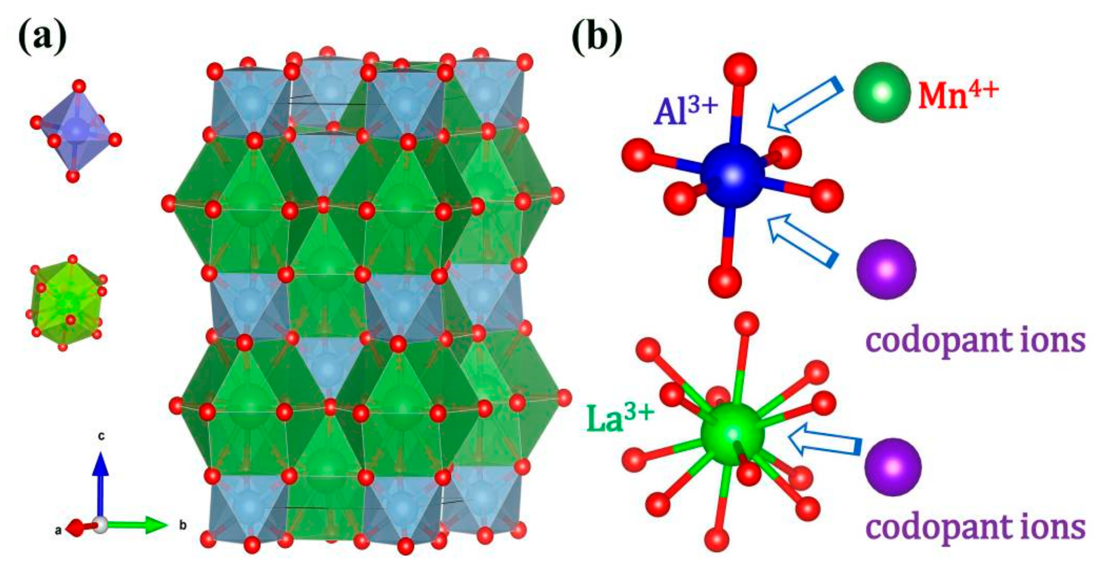
Figure 1a shows the crystal structure of LaAlO3 drawn on the basis of the Inorganic Crystal Structure Database (ICSD No. 153821). LaAlO3 is described in the trigonal crystal system with space group R-3cH (space group number 167) and lattice parameters a = 5.3598 Å, b = 5.3598 Å, c = 13.086 Å, Volume = 325.56 Å3 and z = 6 [26]. As is shown in Figure 1a, the crystal structure corresponds to the rhombohedral, nearly cubic perovskite structure, which involves a rotation of the AlO6 octahedra with respect to cubic perovskite as reported elsewhere [27,28]. There are two types of units in the crystal structure: AlO6 octahedra and LaO12 polyhedra. The central Al3+ cation is in 6-fold oxygen coordination and forms AlO6 octahedral units (blue unit in Figure 1). The La3+ cations are located in a polyhedral unit with 12-fold oxygen coordination (green unit in Figure 1). It is reported that the La-sites have D3 point symmetry [29] and Cr3+-doped LAO confirm a C3i symmetry for the Al site [30]. Both cation sites thus have reduced symmetry from pure Oh symmetry, which results from a contraction along and a small rotation of AlO6 octahedra around the c-axis of the LAO host. However, an inversion center is maintained for the Al-site. The reduction from pure octahedral symmetry is expected to result in a small splitting of the 2E level and thus the zero-phonon transition of Mn4+. The ionic radius of the Mn4+ ion, Al3+ ion and La3+ ion is 53 pm, 53.5 pm and 136 pm in 6-fold octahedral coordination (Mn4+ ion, Al3+ ion) and 12-fold coordination (La3+ ion), respectively [31]. It is well known that the Mn4+ ion usually stabilizes in an octahedral site with 6-fold coordination [21], thus, Mn4+ ions will supposedly occupy the Al3+ ion sites in the LaAlO3 host as shown in Figure 1b. The similar ionic radius helps the substitution between dopant Mn4+ ion and central Al3+ ion in the AlO6 octahedra.
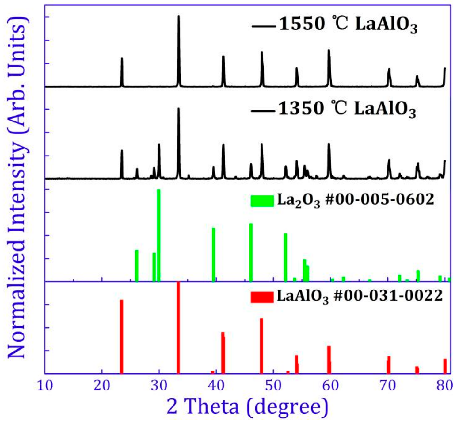
XRD (X-ray diffraction) patterns of un-doped LaAlO3 sintered at 1350 °C, 1400 °C, 1450 °C, 1500 °C, 1550 °C, 1600 °C and 1650 °C are shown in Figure S1. At higher sintering temperatures (above 1550 °C), the XRD patterns of these samples match well with the standard XRD data of LaAlO3 (No. 00-031-0022). At lower sintering temperatures, especially at 1350 °C, a different pattern is displayed. XRD patterns of samples synthesized at 1350 °C and 1550 °C are compared in Figure 2. The impurity phase at 1350 °C is found to be La2O3 (as shown in Figure 2) and the optimized temperature for synthesizing LaAlO3 was chosen at 1550 °C. The standard XRD data of LaAlO3 (No. 00-031-0022) and La2O3 (No. 00-005-0602) are illustrated in red and green bars respectively in Figure 2. Detailed XRD patterns of the obtained LaAlO3 phosphor with different concentrations of Mn4+ and Mn4+,R sintered at 1550 °C demonstrate that doping of Mn4+ ions or Mn4+,R (R = Ge4+, Si4+, Ti4+, Zr4+, Ba2+, Ca2+, Mg2+, Sr2+, Cl−, Li+, Na+) co-dopants does not cause any significant structural changes of the LaAlO3 host for any of the dopants (XRD patterns not shown). Energy-dispersive X-ray (EDS) mapping indicates the homogeneous distribution of manganese in the host (not shown). In agreement with the previous reports, doping of manganese ions is perfectly feasible in the LaAlO3 host [19,32].
2.2. Luminescence Properties
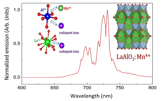
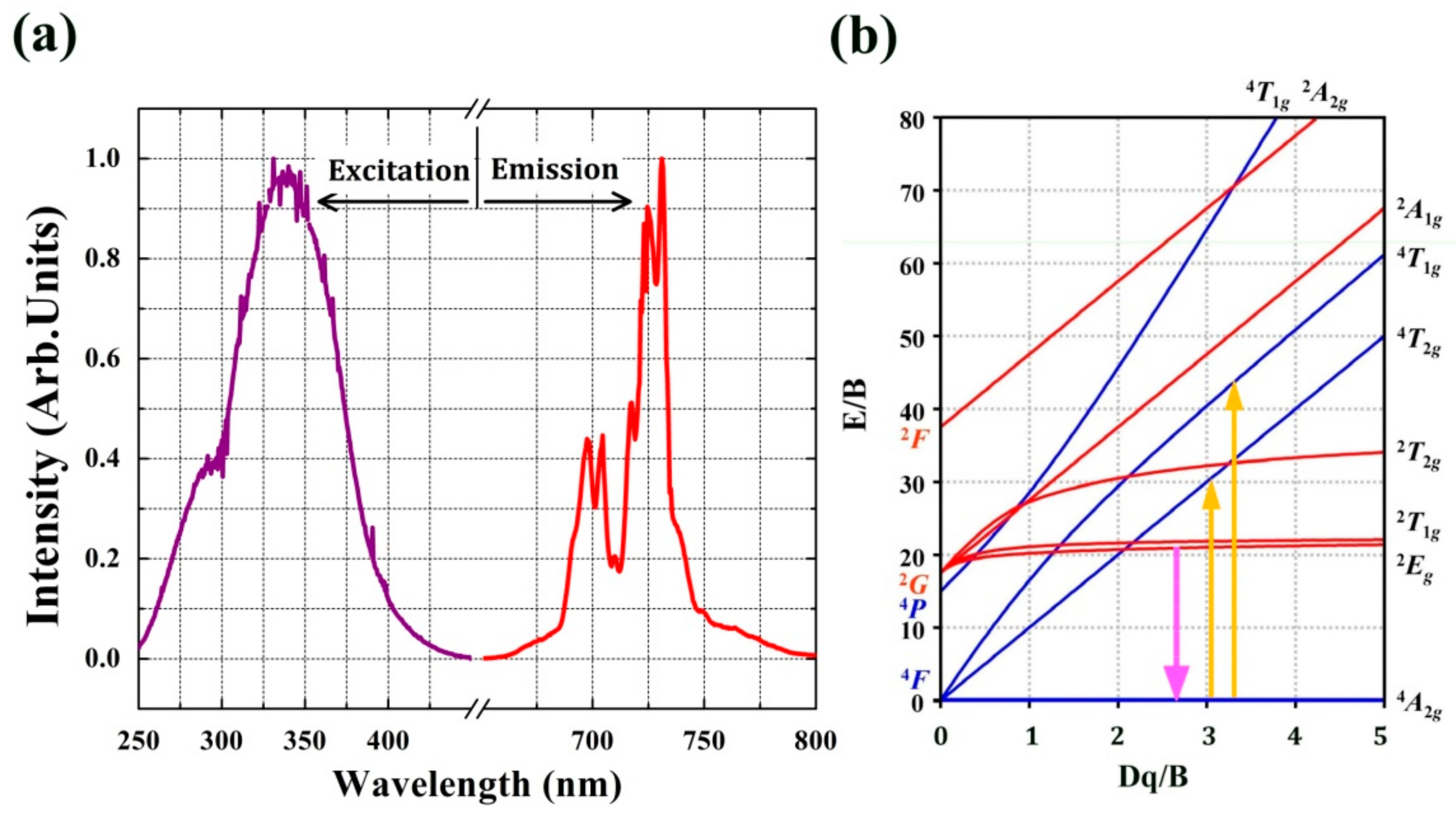
The room-temperature photoluminescence (PL) spectrum of LaAlO3:0.5%Mn4+ phosphor upon excitation at 335 nm exhibits narrow emission bands in the range 650–800 nm due to the 2Eg→4A2g spin-forbidden transitions in Mn4+ ions, with a maximum located at 731 nm as shown in Figure 3a. The spectrum consists of several sharp features, peaking at (from left to right) 697.5 nm, 704.5 nm, 710.5 nm, 718 nm, 724.5 nm and 731 nm, corresponding to the spin-forbidden 2Eg→4A2g transition and the vibrational sidebands of zero-phonon line (ZPL) with phonon assistance. Due to its high effective positive charge, Mn4+ experiences a large crystal field and hence no transitions from the 4T2 level are expected, in contrast to Cr3+-based phosphors [17]. The zero-phonon line (ZPL) is located at 718 nm in Figure 3. The ZPL is surrounded by both anti-Stokes and Stokes phonon side bands. The ZPL here (718 nm, ~13927 cm−1) has a larger wavelength than the value of 712 nm (~14045 cm−1), measured at 300 K and reported by Van Ipenburg et al. [33] but corresponds to the value reported by Li et al. [19]. An assignment of the sidebands to the type of vibration was done by Van Ipenburg et al. [33] and the anti-Stokes sidebands at 697.5 nm, 704.5 nm and 710.5 nm appear in our sample. The 2Eg→4A2g transition has a small electron-phonon coupling and the excited ions usually relax non-radiatively to 2Eg followed by the spin-forbidden 2Eg→4A2g transition, thus resulting in narrow-band emission lines. This is in contrast with the broad bands in the excitation spectrum that correspond to spin-allowed 4A2→4T1 and 4A2→4T2 transitions, with larger electron-phonon coupling [23,34]. It has been widely reported that the spectra of Mn4+ ions exhibit a combination of broadband excitation bands and sharp emission lines [34,35]. Usually, the excitation and emission peaks of Mn4+ ions in many other oxide hosts are observed around 300 nm and above 650 nm, respectively [36,37,38]. This PL behavior proves that Mn is indeed incorporated in the LaAlO3 lattice and is incorporated in a 4+ oxidation state, since Mn2+ is expected to show an entirely different and broad emission spectrum. Mostly, the excitation spectrum of Mn2+ is very characteristic for the d5 electron configuration. The photoluminescence excitation (PLE) spectrum of the phosphor at room temperature is also shown in Figure 3a. The PLE spectrum (λem = 731 nm) shows a broad band with the main peak located at 335 nm and ranging from 250 nm to 450 nm. The broad PLE band is mainly attributed to 4A2→4T1 and 4A2→4T2 transitions of Mn4+ ion as illustrated in the Tanabe-Sugano energy level diagram for 3d3 ions [39]. When Mn4+ ions are situated in the LaAlO3 host with octahedral coordination, the dependence of energy levels of Mn4+ on crystal field strength can be clearly illustrated by the Tanabe-Sugano energy level diagram in Figure 3b. A comparison of PL spectra of LaAlO3:0.1%Mn4+, LaAlO3:0.2%Mn4, LaAlO3:0.5%Mn4+, LaAlO3:1%Mn4+, LaAlO3:2%Mn4+ and LaAlO3:5%Mn4+ is illustrated in Figure 4. The PL intensity of LaAlO3:Mn4+ phosphors increases with increasing Mn4+ ion concentration within the range 0.1% to 0.5% and decreases upon further increasing Mn4+ ion concentration from 0.5% to 5%. The former effects are presumably due to the effective Mn4+ concentration, which dominatingly determines PL intensity in this host. When the content of the doping Mn4+ ions is relatively low, the effective Mn4+ concentration is approximately proportional to the content of the doping Mn4+ ions. Thus, increasing the content of Mn4+ ions from 0.1% to 0.5%, the PL intensity of LaAlO3:Mn4+ phosphors increases synchronously. The latter observation could be attributed to the concentration quenching phenomenon of Mn4+ ions. It can be seen that the optimal doping concentration of Mn4+ ions is 0.5%.
Figure 5 shows the persistent luminescence decay curves of LaAlO3:0.1%Mn4+, LaAlO3:0.2%Mn4+, LaAlO3:0.5%Mn4+, LaAlO3:1%Mn4+, LaAlO3:2%Mn4+, LaAlO3:5%Mn4+ phosphors after 5 min of irradiation with a Xenon arc lamp. It was also found that 0.5% Mn4+ is also the optimal doping concentration for the afterglow intensity and duration.
2.3. Charge Compensation Strategy
To enhance the photoluminescence and afterglow performance of Mn4+-activated LaAlO3 phosphor, a charge compensation strategy was proposed. As mentioned before, Mn4+ ions are supposed to substitute the Al3+ ions in the LaAlO3 host. Thus, a charge imbalance occurs when the substitution happens. With the aid of lower valence state ions to balance the superfluous positive charge of tetravalent manganese, charge compensation is expected. A schematic of charge compensation strategies is illustrated in Figure 6 for LaAlO3:Mn4+ phosphor. For the divalent cations such as Ca2+ in Figure 6a, the unit of Mn4+-Ca2+ can be selected as a substitutable alternative to the unit of Al3+-La3+ to the charge compensation. As for the monovalent cations (for example, Na+ in Figure 6b), the units of Mn4+-Na+-Mn4+ and Al3+-La3+-Al3+ are equivalent in number of charges. We expect Mn4+ to substitute for Al3+ and Ca2+ to substitute for La3+ based on the following considerations: Ionic radii, coordinated environment and chemical stability. For chemical stability, it is well known that the Mn4+ ion usually stabilizes in an octahedral site with 6-fold coordination (in Al3+ site). Mn4+ ion could hardly be situated in 12-fold coordinated environment (La3+ site). In an octahedral environment (in Al3+ site), the Mn-3d states are split into three- and two-fold degenerate t2g and eg states, respectively. The three Mn-3d electrons of Mn4+ exactly fill the majority-spin t2g states. The crystal field splitting creates a large gap between the t2g and eg states, stabilizing the 4+ oxidation state [21,40,41]. Therefore, Mn4+ ions are usually found on octahedral sites of solids [40,41]. For Ge4+ and Ti4+, they also have a stable chemical environment like the Mn4+ ion, so we adopted these ions as co-dopants.
Suitable charge-compensating co-dopants should fulfill certain requirements. The difference in ionic radius between doping ions and central ions plays a critical role in possible substitution and consummate incorporation. The substitution of ions in a crystal lattice has been discussed in depth [42]. It is possible to replace an ion in a specific lattice position with a dopant and not disturb the crystal structure when both ions differ in size by no more than a certain radius ratio for a given coordination number, according to the work of Linus Pauling [42]. It is expected that a smaller radius difference (no more than 15% or 20%) leads to a better substitution. 6-fold coordinated Al3+ ion has an ionic radius of 53.5 pm and 12-fold coordinated La3+ ion has an ionic radius of 136 pm. Figure 7 shows the radius difference between possible doping ions and central ions [31]. Ions in blue stars are supposed to substitute on the Al3+ site with coordination number VI and ions while half-filled pink hexagons are supposed to substitute on the La3+ site with coordination number XII (details in Tables S1 and S2). Both tetravalent cations and lower valence state ions are selected for comparison. Stars and hexagons located in the green wireframe are feasible candidates for doping, considering the similarity in ionic radius and coordinated environment in the host. In the case of LaAlO3, Ge4+ ions and Na+, Ca2+, Sr2+ ions are located in the two green wireframes. Ge4+ ions are supposed to replace Al3+ ions, while Na+, Ca2+ and Sr2+ ions are substitutable for La3+ ions (shown in Figure 6).
2.4. Influence of Various Co-Dopants
To obtain systematic information on the influence of other dopants, various kinds of ions can be taken into account. Some other research groups also found that tetravalent cations (such as Ge4+) or negative charge ions (such as Cl−) could be added as co-dopants in CaAl12O19 and SrMgAl10O17 hosts [43,44,45]. Thus, tetravalent cations (Ge4+, Si4+, Ti4+, Zr4+), divalent cations (Ba2+, Ca2+, Mg2+, Sr2+), monovalent cations (Li+, Na+) and negative charge ions (Cl−) were all selected as discussed above. A series of 2%Mn4+,2%R (R = Ge4+, Si4+, Ti4+, Zr4+, Ba2+, Ca2+, Mg2+, Sr2+, Li+, Na+, Cl−) co-doped phosphors were synthesized at 1550 °C and PL measurements were performed at room temperature. PL spectra of 2%Mn4+,2%R (R = Ge4+, Si4+, Ti4+, Zr4+, Ba2+, Ca2+, Mg2+, Sr2+, Li+, Na+, Cl−) phosphors are shown in Figures S2–S4. Some co-dopants such as Li+, Mg2+ and Si4+ ions did not contribute much to the enhancement of PL intensity. Interestingly, it was found that co-doping with R (R = Na+, Cl−, Ge4+, Ca2+, Sr2+ and Ba2+) increases the PL intensity of LaAlO3:2%Mn4+ phosphor. In particular, the PL emission of LaAlO3:2%Mn4+,2%Na+, LaAlO3:2%Mn4+,2%Ca2+, LaAlO3:2%Mn4+,2%Ba2+, and LaAlO3:2%Mn4+,2%Sr2+ was several times stronger than that of LaAlO3:2%Mn4+ phosphor. It indicates that employing the charge compensation strategy with appropriate co-dopants such as Na+, Cl−, Ge4+, Ca2+, Sr2+ and Ba2+ ions helps to achieve the improvement of luminescence. Mn4+ ions and these R co-dopants were successfully incorporated into the LaAlO3 host compound.
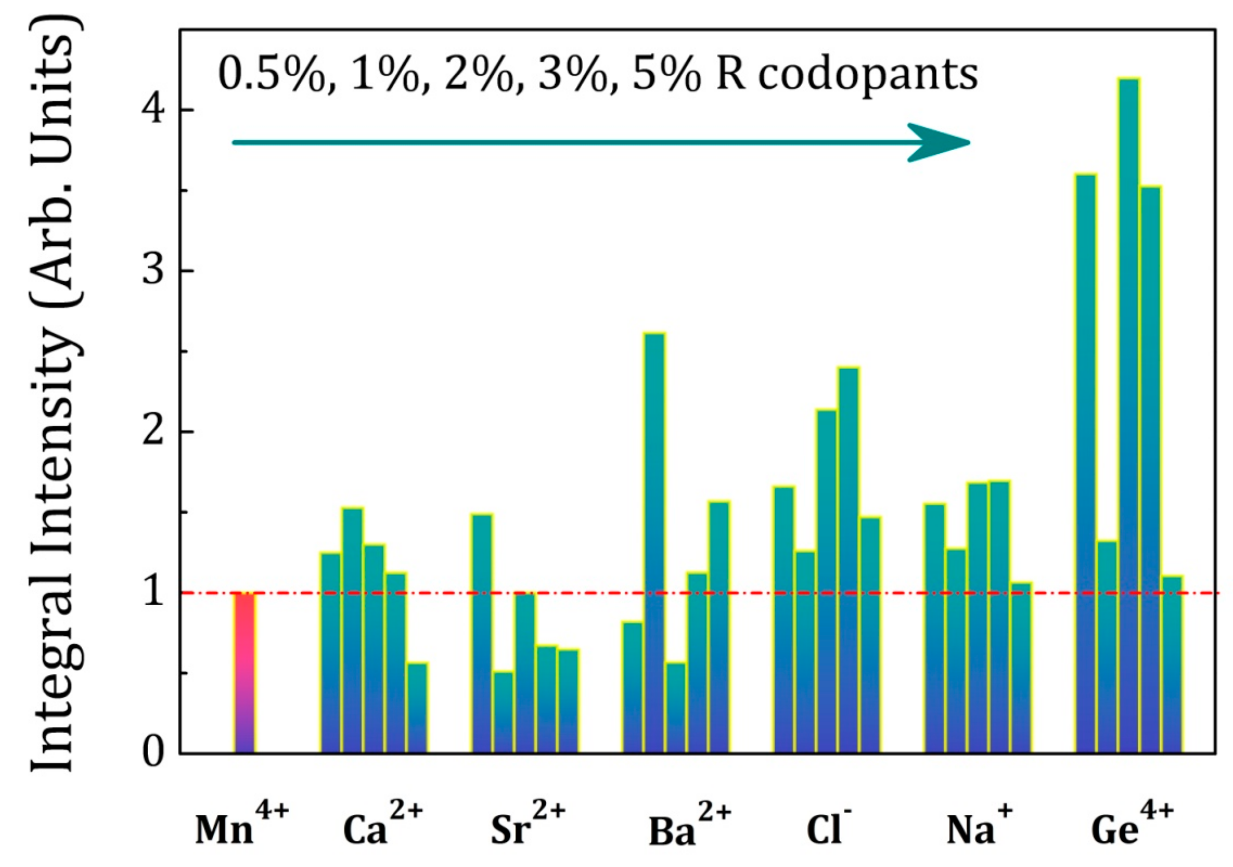
In order to optimize the properties of LaAlO3:Mn4+ phosphors with the charge compensation strategy, six groups of LaAlO3:Mn4+, R (R = Na+, Cl−, Ge4+, Ca2+, Sr2+, Ba2+) phosphors with different co-dopant concentrations were synthesized using the same conditions as discussed above, now using the optimum Mn4+ concentration of 0.5%. The concentration of R (R = Na+, Cl−, Ge4+, Ca2+, Sr2+, Ba2+) was0.5%, 1%, 2%, 3% and 5%. The persistent luminescence decay curves were measured after 5 min of irradiation with a Xenon arc lamp and the detailed persistent luminescence decay curves of LaAlO3:0.5%Mn4+,yR (R = Na+, Cl−, Ge4+, Ca2+, Sr2+, Ba2+; y = 0.5%, 1%, 2%, 3% and 5%) phosphors are shown respectively in Figures S5–S10. A comparison of the afterglow duration time of the six groups is illustrated in Figure 8, showing the time after excitation when the intensity of the afterglow luminescence drops to 5 × 10⁻⁴ mW/sr/m2. This benchmark intensity roughly corresponds to the same intensity as the 0.3 mcd/m2 value, used as a benchmark for visible persistent luminescence [3]. The first red column corresponds to LaAlO3:0.5%Mn4+ as an intensity and duration reference of persistent luminescence. The concentration of R (R = Ca2+, Sr2+, Ba2+, Cl−, Na+, Ge4+) is increasing from left to right in each doping group in Figure 8. The afterglow duration time is prolonged when increasing the concentration of co-dopants and decreases upon further increasing concentrations in the case of Ca2+, Sr2+, Cl− co-dopants, similar to the Mn4+ doping behavior as discussed above in Figure 5. For other co-dopants, the trend turns abnormal due to the complex interactions between the traps and defects. All the co-dopants chosen in this research can help to improve the persistent luminescence and strengthen the afterglow duration time to different extent with various doping concentrations. Steady state photoluminescence spectra of the six groups of LaAlO3:Mn4+,R (R = Na+, Cl−, Ge4+, Ca2+, Sr2+, Ba2+) phosphors were measured at room temperature. For each group of LaAlO3:Mn4+,R phosphors with different co-dopant concentrations, the intensities of photoluminescence were enhanced to a different extent for certain doping concentrations and PL spectra are shown in Figures S11–S16. This also proves the feasibility of the charge compensation strategy for LaAlO3:Mn4+ phosphors. Figure 9 exhibits a map of the integrated intensity of photoluminescence from Mn4+ with R (R = Ca2+, Sr2+, Ba2+, Cl−, Na+, Ge4+) co-dopants. The integral intensity was calculated in the wavelength region from 600 nm to 800 nm. The concentration of Mn4+ ion was 0.5% in each LaAlO3 host and the concentration of R is 0.5%, 1%, 2%, 3% and 5% respectively from left to right in each doping group as illustrated in Figure 9. In order to compare the influence among the different co-dopants with the different R concentrations, the integral intensity of LaAlO3:0.5%Mn4+ emission spectrum was normalized to 1 as a benchmark of emission intensity. It indicates that co-doping with Ge4+, Na+, Cl−, Ba2+, Sr2+ and Ca2+ is beneficial for the enhancement of the PL intensity. Upon doping only one type of dopant, like Mn4+ ions, the PL and afterglow properties of LaAlO3:Mn4+ phosphors have a regular trend when increasing the concentrations of Mn4+ ions from 0.1% to 5% as shown in Figure 4 and Figure 5. However, upon doping two kinds of dopants with the phosphor formula ‘LaAlO3:Mn4+,R’, the possible mechanism and interactions between the traps and defects turns complicated, resulting in an anomalous performance with different concentrations of dopants and co-dopants. The duration and PL intensity of the Mn4+ emission may not simply change monotonously when co-doping another R ions as it is shown in Figure 8 and Figure 9. When co-doping with different ions, even isovalent Ge4+, it is possible that the optimum Mn dopant concentration is changed, again leading to a more complex relation between co-dopant concentration and performance. In view of the improved performance of Mn4+-activated LaAlO3 phosphor, co-dopants chosen in this research can lead to a 2-fold to 4-fold increase of afterglow time and PL intensity with different doping concentrations. Based on this preliminary screening of the performance of different co-dopants, a more in-depth investigation of the effects of co-doping on afterglow performance will be conducted on selected co-dopants, using temperature dependent charging and afterglow experiments and thermoluminescence measurements.
PL intensities and afterglow duration of the LaAlO3:Mn4+ phosphors are determined by the competition between the quantity of the effective Mn4+ ions (defect density of Mn4+ ions) in the phosphors and the interaction among the Mn4+ ions (Mn4+-Mn4+ pairs). We believe that more isolated Mn4+ ions in the phosphors enhance the light emission and more traps and defects strengthen the afterglow duration. However, the formation and interaction from Mn4+-Mn4+ pairs, which are inevitably formed at high annealing temperature as reported in some other papers [43,46], will decrease both defect density and the number of effective Mn4+ ions, resulting in quenching the emission and shorten afterglow duration. From the Figure 8 and Figure 9, both the photoluminescence and persistent luminescence can be enhanced to a certain extent when employing the appropriate co-dopants such as Na+, Cl−, Ca2+, Ba2+, Sr2+ and Ge4+ ions. As for the improvement of persistent luminescence, two kinds of active centers are involved in persistent luminescence, namely traps and emitters. Traps originate from lattice defects or co-dopants in the phosphor and emitters release light in the region of interest. It is known that Mn4+ ion can act as both the trapping center and the emitting center in the perovskite LaAlO3 host [19]. The afterglow duration thus relies on the effective defect density of Mn4+ ions as trapping centers. In addition, Mn4+ trapping centers have a complex dependency on the concentration of incorporated manganese ions and Mn4+-Mn4+ pairs [43]. Mn4+-Mn4+ pairs decrease the effective defect density of Mn4+ ions and weaken the persistent luminescence. The afterglow of this material is constrained by the formation of Mn4+-Mn4+ pairs in the host, resulting in a lower effective defect density. The challenge in the perovskite LaAlO3 host is to incorporate more Mn4+ ions as traps and avoid Mn4+-Mn4+ pairs. Charge-compensating co-dopants help to impede the formation of Mn4+-Mn4+ pairs. In this material, the effective incorporation and increasing defect density are strongly improved by co-doping with Ge4+ or ions with a lower valence state for charge compensation, such as divalent cations (Ca2+, Ba2+ or Sr2+ ions), monovalent cations (Na+ ions) or ions in their negative valence (Cl− ions). Thus, the enrichment of the effective defect density prolongs the persistent luminescence. As for the photoluminescence enhancement, the origin of this phenomenon is widely understood and explained by the charge compensation mechanism. The photoluminescence intensity is determined by the complex competition between the effective amount of Mn4+ ions and quantity of the Mn4+-Mn4+ pairs in LaAlO3:Mn4+ phosphors. It is believed that more effective Mn4+ ions increase the PL intensity while the Mn4+-Mn4+ pairs quench the emission. The interaction of Mn4+-Mn4+ pairs is related to the Mn4+-Mn4+ distance [43]. Substitution of 6-fold coordinated octahedral Al3+ ion or 12-fold coordinated central La3+ ion with a lower charge state is supposed to create a negative local charge, which improves the efficiency of Mn4+ ions to replace Al3+ sites, thus increasing the effective amount of Mn4+ ions. Furthermore, the incorporation with lower valence state ions guarantees the charge equilibrium, which restrains the formation of Mn4+-Mn4+ pairs leading to the enhancement of PL intensity [44]. That is the case for divalent cations (Ca2+, Ba2+ or Sr2+ ions), monovalent cations (Na+ ions) and negative valence ions (Cl− ions). Tetravalent cations such as Ge4+ ions are competitive with the substitution by Mn4+ due to the same valence state. However, the co-dopant Ge4+ ions may enrich the defect density and play an effective role in decreasing the formation and interaction of Mn4+-Mn4+ pairs, resulting as a compensator to Mn4+-Mn4+ pairs and enhancing the PL intensity [19,43]. In the case of the perovskite LaAlO3 host, the compensation effect of co-doping Mn4+/Ge4+ ions is found to occupy a predominant position.
3. Materials and Methods
All the raw chemicals were analytical grade, used without further purification. The precursors were La2O3 (Sigma Aldrich, Saint Louis, MO, USA, 99.99%), Al2O3 (Fluka, Schwerte, Germany, 99.5%), MnO2 (Alfa Aesar, Karlsruhe, Germany, 99.997%), NH4Cl (Alfa Aesar, 99.999%), Li2CO3 (Alfa Aesar, 99.998%), Na2CO3 (Alfa Aesar, 99.95%), MgO (Alfa Aesar, 99.95%), CaCO3 (Alfa Aesar, 99.95%), SrCO3 (Alfa Aesar, 99.99%), BaCO3 (Alfa Aesar, 99.95%), SiO2 (Alfa Aesar, 99.5%), GeO2 (Alfa Aesar, 99.999%), TiO2 (Alfa Aesar, 99.995%), ZrO2 (Alfa Aesar, 99.978%). The concentrations of dopants were chosen as follows: LaAlO3:xMn4+ (x = 0.1%, 0.2%, 0.5%, 1%, 2% and 5%); LaAlO3:2%Mn4+,2%R; LaAlO3:0.5%Mn4+,yR (y = 0.5%, 1%, 2%, 3% and 5%). The molar % is defined with respect to one mole of a host phosphor chemical formula. The appropriate stoichiometric number of precursors were weighed and manually ground in an agate mortar. Subsequently, the starting materials were mixed with ethanol and put in a ZrO2 grinding jar. Grinding was performed in a Retsch PM 100 Planetary ball mill for 6 h to reduce the particle size. After evaporating the remaining ethanol, repeated grinding was performed in an agate mortar to improve the mixing homogeneity of the precursors. The phosphors of LaAlO3:Mn4+ and a series of LaAlO3:Mn4+,R (R = Cl−, Li+, Na+, Mg2+, Ca2+, Sr2+, Ba2+, Si4+, Ge4+, Ti4+, Zr4+) were synthesized through a traditional high-temperature solid-state reaction method, testing various temperatures between 1350 °C and 1650 °C, for 6 h in air. The employed heating rate was 300 °C/h using a tube furnace (ETF30-50/18-S furnace, ENTECH, Ängelholm, Sweden). All samples were allowed to cool naturally inside the tube furnace. The sintered samples were well ground again. To compare the luminescence properties and afterglow intensity, all the phosphors were synthesized under the same experimental conditions.
The crystal structures of LaAlO3:Mn4+ and LaAlO3:Mn4+, R were characterized by Powder X-ray diffraction (XRD) (Bruker, Leiderdorp, The Nederlands). Crystallographic phases of the obtained powders were verified on a Siemens D5000 diffractometer (40 kV, 40 mA, Bruker) using Cu Kα1 radiation (λ = 0.154 nm). The XRD data were collected in the range 2θ from 10° to 80° at room temperature. A comparison of the obtained XRD patterns with the reference pattern (No. 00-031-0022) was made to check the phase purity.
Steady state photoluminescence excitation and emission spectra were measured using an Edinburgh FS920 (Edinburgh Instruments Ltd., Livingston, UK) fluorescence spectrometer with a monochromated 450 W Xe-arc lamp as the excitation source.
The powder was put into a metal disc with a diameter of 12.5 mm and persistent luminescence was measured with a photosensor amplifier (C9329, Hamamatsu, Japan) and a Centronics OSD100-5T (Centronic Ltd., Croydon, UK) silicon photodiode. The afterglow decay profiles were then calibrated to the absolute radiance (in unit of mW/sr/m2), since the usual units of luminance, cd/m2, are not relevant for near-infrared emitting phosphors [3]. All persistent luminescent decay curves of LaAlO3 samples were recorded at room temperature after excitation for 5 min by the light of an unfiltered Xenon arc lamp at an intensity of 1000 lux.
4. Conclusions
In summary, a series of novel near-infrared emitting persistent luminescent phosphors LaAlO3:Mn4+ (LAO:Mn4+) were synthesized by a convenient high-temperature solid-state reaction in air. Various kinds of co-dopants with Mn4+ ions were optimized and incorporated in different concentrations. Impressively, co-dopants such as Cl−, Na+, Ca2+, Sr2+, Ba2+ and Ge4+ ions were all found to be beneficial for improving the LaAlO3:Mn4+ luminescence and afterglow intensity. The charge compensation strategies for LaAlO3:Mn4+ phosphors were systematically discussed. Employing this charge compensation strategy is believed to open up new avenues for the exploration of more promising near-infrared emitting long persistent phosphors for medical imaging.
Supplementary Materials
The following are available online at www.mdpi.com/1996-1944/10/12/1422/s1, Figure S1: XRD pattern of LaAlO3 synthesized through a solid-state reaction method, Figure S2: Photoluminescence (PL) spectra of LaAlO3:2%Mn4+,2%Li+, LaAlO3:2%Mn4+,2%Na+, and LaAlO3:2%Mn4+,2%Cl− phosphors, Figure S3: Photoluminescence (PL) spectra of LaAlO3:2%Mn4+,2%Ge4+, LaAlO3:2%Mn4+,2%Si4+, LaAlO3:2%Mn4+,2%Ti4+, and LaAlO3:2%Mn4+,2%Zr4+ phosphors, Figure S4: Photoluminescence (PL) spectra of LaAlO3:2%Mn4+,2%Ba2+, LaAlO3:2%Mn4+,2%Ca2+, LaAlO3:2%Mn4+,2%Mg2+,and LaAlO3:2%Mn4+,2%Sr2+ phosphors, Figure S5: Persistent luminescence decay curves of LaAlO3:0.5%Mn4+,ySr2+ (y = 0.5%, 1%, 2%, 3%, and 5%) phosphors after 5 min of irradiation with a Xenon arc lamp, Figure S6: Persistent luminescence decay curves of LaAlO3:0.5%Mn4+,yGe4+ (y = 0.5%, 1%, 2%, 3%, and 5%) phosphors after 5 min of irradiation with a Xenon arc lamp, Figure S7: Persistent luminescence decay curves of LaAlO3:0.5%Mn4+,yCa2+ (y = 0.5%, 1%, 2%, 3%, and 5%) phosphors after 5 min of irradiation with a Xenon arc lamp, Figure S8: Persistent luminescence decay curves of LaAlO3:0.5%Mn4+,yBa2+ (y = 0.5%, 1%, 2%, 3%, and 5%) phosphors after 5 min of irradiation with a Xenon arc lamp, Figure S9: Persistent luminescence decay curves of LaAlO3:0.5%Mn4+,yCl− (y = 0.5%, 1%, 2%, 3%, and 5%) phosphors after 5 min of irradiation with a Xenon arc lamp, Figure S10: Persistent luminescence decay curves of LaAlO3:0.5%Mn4+,yNa+ (y = 0.5%, 1%, 2%, 3%, and 5%) phosphors after 5 min of irradiation with a Xenon arc lamp, Figure S11: Photoluminescence (PL) spectra of LaAlO3:0.5%Mn4+,0.5%Ge4+, LaAlO3:0.5%Mn4+,1%Ge4+, LaAlO3:0.5%Mn4+,2%Ge4+, LaAlO3:0.5%Mn4+,3%Ge4+ and LaAlO3:0.5%Mn4+,5%Ge4+ phosphors, Figure S12: Photoluminescence (PL) spectra of LaAlO3:0.5%Mn4+,0.5%Ba2+, LaAlO3:0.5%Mn4+,1%Ba2+, LaAlO3:0.5%Mn4+,2%Ba2+, LaAlO3:0.5%Mn4+,3%Ba2+ and LaAlO3:0.5%Mn4+,5%Ba2+ phosphors, Figure S13: Photoluminescence (PL) spectra of LaAlO3:0.5%Mn4+,0.5%Sr2+, LaAlO3:0.5%Mn4+,1%Sr2+, LaAlO3:0.5%Mn4+,2%Sr2+, LaAlO3:0.5%Mn4+,3%Sr2+ and LaAlO3:0.5%Mn4+,5%Sr2+ phosphors, Figure S14: Photoluminescence (PL) spectra of LaAlO3:0.5%Mn4+,0.5%Ca2+, LaAlO3:0.5%Mn4+,1%Ca2+, LaAlO3:0.5%Mn4+,2%Ca2+, LaAlO3:0.5%Mn4+,3%Ca2+ and LaAlO3:0.5%Mn4+,5%Ca2+ phosphors, Figure S15: Photoluminescence (PL) spectra of LaAlO3:0.5%Mn4+,0.5%Na+, LaAlO3:0.5%Mn4+,1%Na+, LaAlO3:0.5%Mn4+,2%Na+, LaAlO3:0.5%Mn4+,3%Na+ and LaAlO3:0.5%Mn4+,5%Na+ phosphors, Figure S16: Photoluminescence (PL) spectra of LaAlO3:0.5%Mn4+,0.5%Cl−, LaAlO3:0.5%Mn4+,1%Cl−, LaAlO3:0.5%Mn4+,2%Cl−, LaAlO3:0.5%Mn4+,3%Cl− and LaAlO3:0.5%Mn4+,5%Cl− phosphors, Table S1: Ionic radius of some common dopant cations for the substitution on Al3+ site, Table S2: Ionic radius of some common dopant cations for the substitution on La3+ site.
Acknowledgments
Jiaren Du gratefully acknowledges the China Scholarship Council (Grant number 201606170077). Olivier Q. De Clercq acknowledges the financial support of the Ghent University’s Special Research Fund (BOF).
Author Contributions
Dirk Poelman and Jiaren Du conceived and designed the experiments; Jiaren Du performed the experiments; Dirk Poelman, Jiaren Du, Olivier Q. De Clercq and Katleen Korthout the authors analyzed the data and wrote the paper.
Conflicts of Interest
The authors declare no conflict of interest.
References
- Matsuzawa, T.; Aoki, Y.; Takeuchi, N.; Murayama, Y. A new long phosphorescent phosphor with high brightness, SrAl2O4:Eu2+, Dy3+. J. Electrochem. Soc. 1996, 143, 2670–2673. [Google Scholar] [CrossRef]
- Aitasalo, T.; Dereń, P.; Hölsä, J.; Jungner, H.; Krupa, J.-C.; Lastusaari, M.; Legendziewicz, J.; Niittykoski, J.; Stręk, W. Persistent luminescence phenomena in materials doped with rare earth ions. J. Solid State Chem. 2003, 171, 114–122. [Google Scholar] [CrossRef]
- Smet, P.F.; Van den Eeckhout, K.; De Clercq, O.Q.; Poelman, D. Persistent phosphors. In Handbook on the Physics and Chemistry of Rare Earths; Elsevier: Amsterdam, The Netherlands, 2015; Volume 48, pp. 1–108. [Google Scholar]
- Viana, B.; Sharma, S.; Gourier, D.; Maldiney, T.; Teston, E.; Scherman, D.; Richard, C. Long term in vivo imaging with Cr3+ doped spinel nanoparticles exhibiting persistent luminescence. J. Lumin. 2016, 170, 879–887. [Google Scholar] [CrossRef]
- Li, Y.; Gecevicius, M.; Qiu, J. Long persistent phosphors- from fundamentals to applications. Chem. Soc. Rev. 2016, 45, 2090–2136. [Google Scholar] [CrossRef] [PubMed]
- Yamamoto, H.; Matsuzawa, T. Mechanism of long phosphorescence of SrAl2O4:Eu2+, Dy3+ and CaAl2O4:Eu2+, Nd3+. J. Lumin. 1997, 72, 287–289. [Google Scholar] [CrossRef]
- De Chermont, Q.L.M.; Chanéac, C.; Seguin, J.; Pellé, F.; Maîtrejean, S.; Jolivet, J.-P.; Gourier, D.; Bessodes, M.; Scherman, D. Nanoprobes with near-infrared persistent luminescence for in vivo imaging. Proc. Natl. Acad. Sci. USA 2007, 104, 9266–9271. [Google Scholar] [CrossRef] [PubMed]
- Smith, A.M.; Mancini, M.C.; Nie, S. Bioimaging: Second window for in vivo imaging. Nat. Nanotechnol. 2009, 4, 710–711. [Google Scholar] [CrossRef] [PubMed]
- Duan, H.; Nie, S. Cell-penetrating quantum dots based on multivalent and endosome-disrupting surface coatings. J. Am. Chem. Soc. 2007, 129, 3333–3338. [Google Scholar] [CrossRef] [PubMed]
- Chen, G.; Ohulchanskyy, T.Y.; Kumar, R.; Ågren, H.; Prasad, P.N. Ultrasmall monodisperse NaYF4:Yb3+/Tm3+ nanocrystals with enhanced near-infrared to near-infrared upconversion photoluminescence. ACS Nano 2010, 4, 3163–3168. [Google Scholar] [CrossRef] [PubMed]
- Singh, S. Red and near infrared persistent luminescence nano-probes for bioimaging and targeting applications. RSC Adv. 2014, 4, 58674–58698. [Google Scholar] [CrossRef]
- Maldiney, T.; Viana, B.; Bessière, A.; Gourier, D.; Bessodes, M.; Scherman, D.; Richard, C. In vivo imaging with persistent luminescence silicate-based nanoparticles. Opt. Mater. 2013, 35, 1852–1858. [Google Scholar] [CrossRef]
- Bessière, A.; Jacquart, S.; Priolkar, K.; Lecointre, A.; Viana, B.; Gourier, D. ZnGa2O4:Cr3+: A new red long-lasting phosphor with high brightness. Opt. Express 2011, 19, 10131–10137. [Google Scholar] [CrossRef] [PubMed]
- Pan, Z.; Lu, Y.-Y.; Liu, F. Sunlight-activated long-persistent luminescence in the near-infrared from Cr3+-doped zinc gallogermanates. Nat. Mater. 2012, 11, 58. [Google Scholar] [CrossRef] [PubMed]
- Li, Y.; Zhou, S.; Li, Y.; Sharafudeen, K.; Ma, Z.; Dong, G.; Peng, M.; Qiu, J. Long persistent and photo-stimulated luminescence in Cr3+-doped Zn–Ga–Sn–O phosphors for deep and reproducible tissue imaging. J. Mater. Chem. C 2014, 2, 2657–2663. [Google Scholar] [CrossRef]
- Liu, F.; Yan, W.; Chuang, Y.-J.; Zhen, Z.; Xie, J.; Pan, Z. Photostimulated near-infrared persistent luminescence as a new optical read-out from Cr3+-doped LiGa5O8. Sci. Rep. 2013, 3, 1554. [Google Scholar] [CrossRef] [PubMed]
- De Clercq, O.Q.; Martin, L.I.; Korthout, K.; Kusakovskij, J.; Vrielinck, H.; Poelman, D. Probing the local structure of the near-infrared emitting persistent phosphor LiGa5O8:Cr3+. J. Mater. Chem. C 2017, 5, 10861. [Google Scholar] [CrossRef]
- De Clercq, O.Q.; Poelman, D. Local, temperature-dependent trapping and detrapping in the LiGa5O8:Cr infrared emitting persistent phosphor. ECS J. Solid State Sci. Technol. 2017, 7, R3171–R3175. [Google Scholar] [CrossRef]
- Li, Y.; Li, Y.-Y.; Sharafudeen, K.; Dong, G.-P.; Zhou, S.-F.; Ma, Z.-J.; Peng, M.-Y.; Qiu, J.-R. A strategy for developing near infrared long-persistent phosphors: Taking MAlO3:Mn4+, Ge4+ (M = La, Gd) as an example. J. Mater. Chem. C 2014, 2, 2019–2027. [Google Scholar] [CrossRef]
- Sijbom, H.F.; Joos, J.J.; Martin, L.I.; Van den Eeckhout, K.; Poelman, D.; Smet, P.F. Luminescent behavior of the K2SiF6:Mn4+ red phosphor at high fluxes and at the microscopic level. ECS J. Solid State Sci. Technol. 2016, 5, R3040–R3048. [Google Scholar] [CrossRef] [Green Version]
- Zhu, H.; Lin, C.C.; Luo, W.; Shu, S.; Liu, Z.; Liu, Y.; Kong, J.; Ma, E.; Cao, Y.; Liu, R.-S. Highly efficient non-rare-earth red emitting phosphor for warm white light-emitting diodes. Nat. Commun. 2014, 5, 4312. [Google Scholar] [CrossRef] [PubMed]
- Liu, J.-M.; Liu, Y.-Y.; Zhang, D.-D.; Fang, G.-Z.; Wang, S. Synthesis of GdAlO3:Mn4+, Ge4+@Au core-shell nanoprobes with plasmon-enhanced near-infrared persistent luminescence for in vivo trimodality bioimaging. ACS Appl. Mater. Interfaces 2016, 8, 29939–29949. [Google Scholar] [CrossRef] [PubMed]
- Sijbom, H.F.; Verstraete, R.; Joos, J.J.; Poelman, D.; Smet, P.F. K2SiF6:Mn4+ as a red phosphor for displays and warm-white LEDs: A review of properties and perspectives. Opt. Mater. Express 2017, 7, 3332–3365. [Google Scholar] [CrossRef]
- Katayama, Y.; Kobayashi, H.; Tanabe, S. Deep-red persistent luminescence in Cr3+-doped LaAlO3 perovskite phosphor for in vivo imaging. Appl. Phys. Express 2014, 8, 012102. [Google Scholar] [CrossRef]
- Xu, J.; Murata, D.; Katayama, Y.; Ueda, J.; Tanabe, S. Cr3+/Er3+ co-doped LaAlO3 perovskite phosphor: A near-infrared persistent luminescence probe covering the first and third biological windows. J. Mater. Chem. B 2017, 5, 6385–6393. [Google Scholar] [CrossRef]
- Hayward, S.; Morrison, F.; Redfern, S.; Salje, E.; Scott, J.; Knight, K.; Tarantino, S.; Glazer, A.; Shuvaeva, V.; Daniel, P. Transformation processes in LaAlO3: Neutron diffraction, dielectric, thermal, optical and Raman studies. Phys. Rev. B 2005, 72, 054110. [Google Scholar] [CrossRef]
- Sanz-Ortiz, M.N.; Rodríguez, F.; Rodríguez, J.; Demazeau, G. Optical and magnetic characterisation of Co3+ and Ni3+ in LaAlO3: Interplay between the spin state and Jahn—Teller effect. J. Phys. Condens. Matter 2011, 23, 415501. [Google Scholar] [CrossRef] [PubMed]
- Srivastava, A.; Brik, M. Crystal field studies of the Mn4+ energy levels in the perovskite, LaAlO3. Opt. Mater. 2013, 35, 1544–1548. [Google Scholar] [CrossRef]
- Faucher, M.; Caro, P. Optical study of LaAlO3:Eu at temperatures approaching the rhombohedric→cubic transition. J. Chem. Phys. 1975, 63, 446–454. [Google Scholar] [CrossRef]
- Wen-Chen, Z. Theoretical studies of the electron paramagnetic resonance and optical spectra of Cr3+ ions in the rhombohedral phase of a LaAlO3 crystal. J. Phys. Condens. Matter 1995, 7, 4499. [Google Scholar] [CrossRef]
- Shannon, R.D. Revised effective ionic radii and systematic studies of interatomic distances in halides and chalcogenides. Acta Crystallogr. A 1976, 32, 751–767. [Google Scholar] [CrossRef]
- Cao, R.; Ceng, D.; Liu, P.; Yu, X.; Guo, S.; Zheng, G. Synthesis and photoluminescence properties of LaAlO3:Mn4+, Na+ deep red-emitting phosphor. Appl. Phys. A 2016, 122, 299. [Google Scholar] [CrossRef]
- Van Ipenburg, M.; Dirksen, G.; Blasse, G. Charge-transfer excitation of transition-metal-ion luminescence. Mater. Chem. Phys. 1995, 39, 236–238. [Google Scholar] [CrossRef]
- Brik, M.; Srivastava, A. On the optical properties of the Mn4+ ion in solids. J. Lumin. 2013, 133, 69–72. [Google Scholar] [CrossRef]
- Brik, M.; Camardello, S.; Srivastava, A. Influence of covalency on the Mn4+ 2Eg→4A2g emission energy in crystals. ECS J. Solid State Sci. Technol. 2015, 4, R39–R43. [Google Scholar] [CrossRef]
- Du, M.-H. Chemical trends of Mn4+ emission in solids. J. Mater. Chem. C 2014, 2, 2475–2481. [Google Scholar] [CrossRef]
- Cao, R.; Zhang, F.; Cao, C.; Yu, X.; Liang, A.; Guo, S.; Xue, H. Synthesis and luminescence properties of CaAl2O4:Mn4+ phosphor. Opt. Mater. 2014, 38, 53–56. [Google Scholar] [CrossRef]
- Seki, K.; Uematsu, K.; Toda, K.; Sato, M. Novel deep red emitting phosphors Ca14Zn6M10O35:Mn4+ (M = Al3+ and Ga3+). Chem. Lett. 2014, 43, 1213–1215. [Google Scholar] [CrossRef]
- Tanabe, Y.; Sugano, S. On the absorption spectra of complex ions II. J. Phys. Soc. Jpn. 1954, 9, 766–779. [Google Scholar] [CrossRef]
- Srivastava, A.M.; Brik, M.G.; Camardello, S.J.; Comanzo, H.A.; Garcia-Santamaria, F. Optical spectroscopy and crystal field studies of the Mn4+ ion (3d3) in the double perovskite NaLaMgTeO6. Z. Naturforschung B 2014, 69, 141–149. [Google Scholar] [CrossRef]
- Zhou, Z.; Zhou, N.; Xia, M.; Yokoyama, M.; Hintzen, H.B. Research progress and application prospects of transition metal Mn4+-activated luminescent materials. J. Mater. Chem. C 2016, 4, 9143–9161. [Google Scholar] [CrossRef]
- Pauling, L. The principles determining the structure of complex ionic crystals. J. Am. Chem. Soc. 1929, 51, 1010–1026. [Google Scholar] [CrossRef]
- Shu, W.; Jiang, L.; Xiao, S.; Yang, X.; Ding, J. GeO2 dopant induced enhancement of red emission in CaAl12O19:Mn4+ phosphor. Mater. Sci. Eng. B 2012, 177, 274–277. [Google Scholar] [CrossRef]
- Xu, Y.; Zhang, Y.; Wang, L.; Shi, M.; Liu, L.; Chen, Y. Red emission enhancement for CaAl12O19:Cr3+ and CaAl12O19:Mn4+ phosphors. J. Mater. Sci. Mater. Electron. 2017, 28, 12032–12038. [Google Scholar] [CrossRef]
- Meng, L.; Liang, L.; Wen, Y. Deep red phosphors SrMgAl10O17:Mn4+, M (M = Li+, Na+, K+, Cl−) for warm white light emitting diodes. J. Mater. Sci. Mater. Electron. 2014, 25, 2676–2681. [Google Scholar] [CrossRef]
- Pan, Y.; Liu, G. Enhancement of phosphor efficiency via composition modification. Opt. Lett. 2008, 33, 1816–1818. [Google Scholar] [CrossRef] [PubMed]
Figure 1.
(a) Crystal structure of LaAlO3 (blue unit is AlO6 octahedron and green unit is LaO12 polyhedron); (b) Doping positions for Mn4+ and other dopant ions, the Mn4+ ion can occupy Al3+ ion site in the AlO6 octahedral unit.
Figure 1.
(a) Crystal structure of LaAlO3 (blue unit is AlO6 octahedron and green unit is LaO12 polyhedron); (b) Doping positions for Mn4+ and other dopant ions, the Mn4+ ion can occupy Al3+ ion site in the AlO6 octahedral unit.

Figure 2.
A comparison of XRD (X-ray diffraction) patterns between 1350 °C and 1550 °C. The impurity phase in the XRD pattern at 1350 °C is assigned to La2O3 and the optimized temperature for synthesizing is 1550 °C. The standard XRD data of LaAlO3 and La2O3 are illustrated in red and green bars respectively. The intensities of XRD patterns are normalized to arbitrary units [0,1].

Figure 3.
(a) Photoluminescence (PL) and photoluminescence excitation (PLE) spectra of LaAlO3:0.5%Mn4+phosphor. PL and PLE spectra (λex = 335 nm and λem = 731 nm) are in the range 250–450 nm and 650–800 nm, respectively; (b)Tanabe-Sugano energy level diagram of a d3 configuration (Mn4+ion in the octahedron).

Figure 4.
A comparison of photoluminescence (PL) spectra of LaAlO3:0.1%Mn4+, LaAlO3:0.2%Mn4+, LaAlO3:0.5%Mn4+, LaAlO3:1%Mn4+, LaAlO3:2%Mn4+ and LaAlO3:5%Mn4+ phosphors. The emission spectrum is acquired under 335 nm excitation. The inset gives the relative emission intensity while increasing Mn4+ doping concentration from 0.1% to 5%.
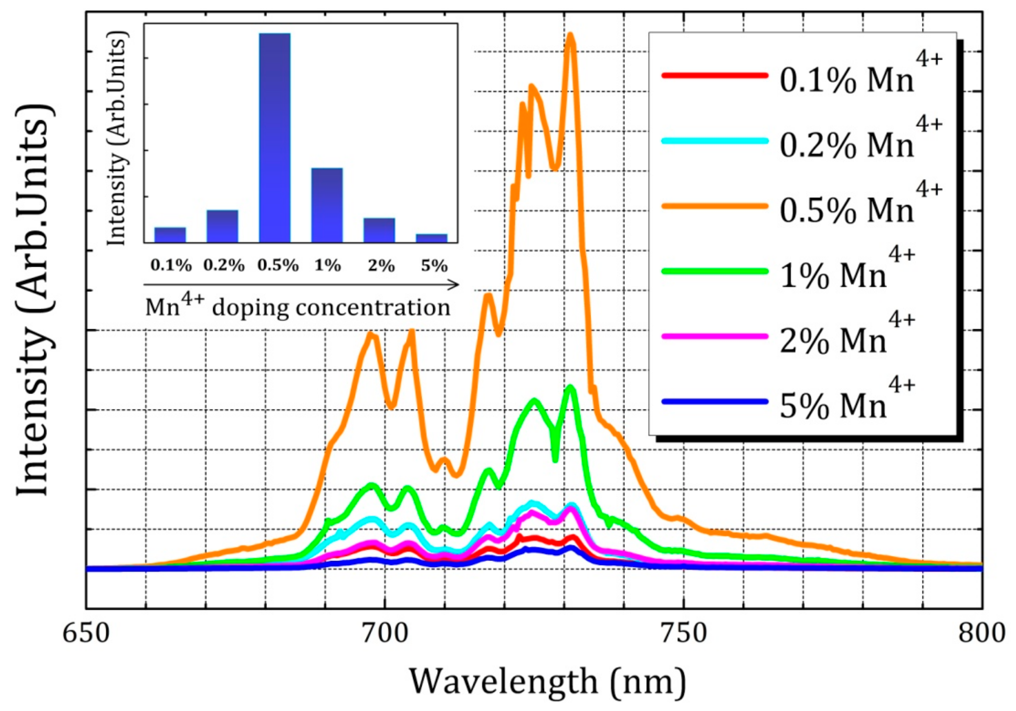
Figure 5.
Persistent luminescence decay curves of Mn4+-doped LaAlO3 phosphors after 5 min of irradiation with a Xenon arc lamp. The concentrations of Mn4+ions in LaAlO3host are 0.1%, 0.2%, 0.5%, 1%, 2%, 5% as shown in different colors.
Figure 5.
Persistent luminescence decay curves of Mn4+-doped LaAlO3 phosphors after 5 min of irradiation with a Xenon arc lamp. The concentrations of Mn4+ions in LaAlO3host are 0.1%, 0.2%, 0.5%, 1%, 2%, 5% as shown in different colors.
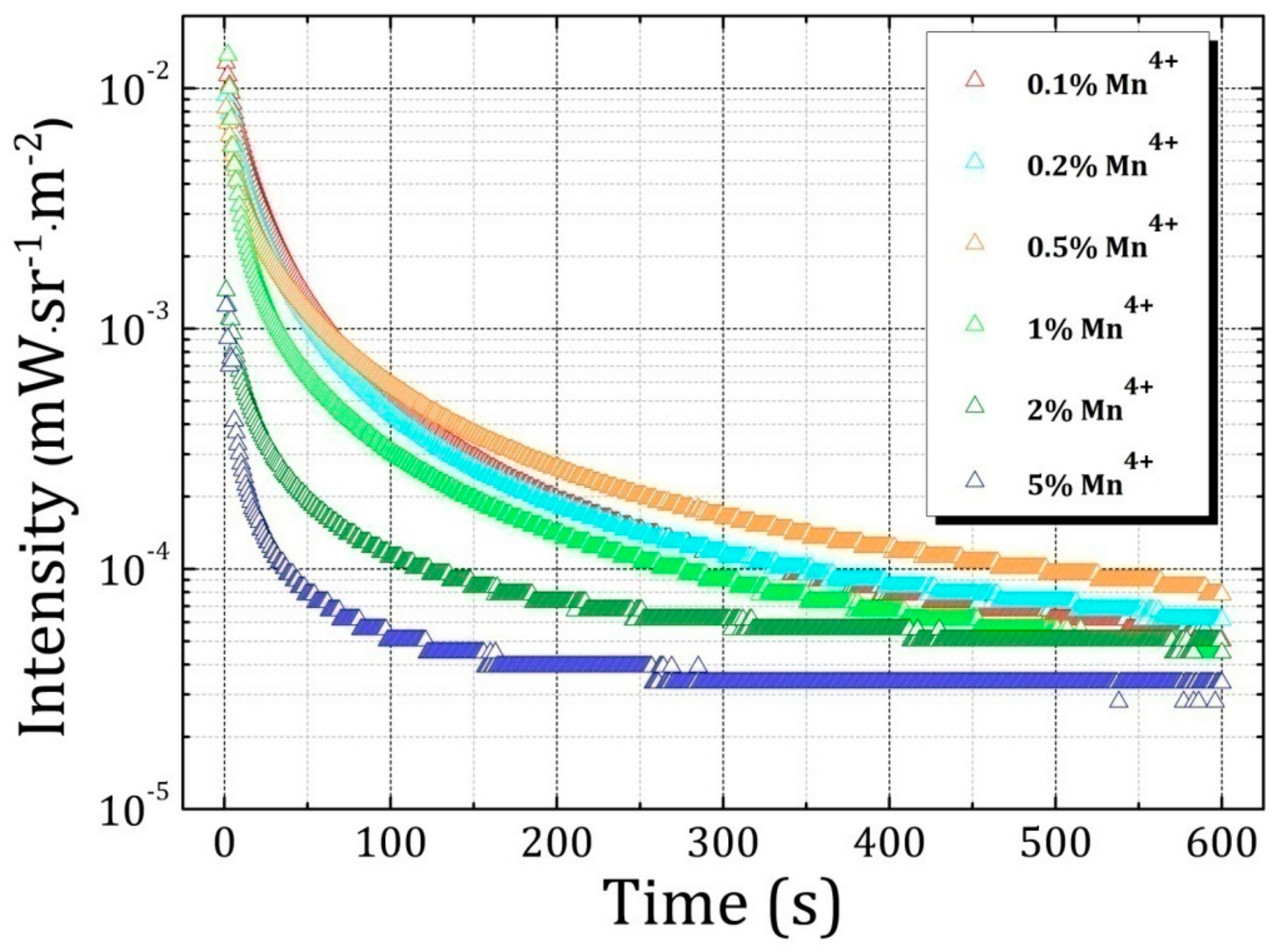
Figure 6.
A schematic of charge compensation strategies for LaAlO3:Mn4+ phosphor. (a) The charge compensation for the unit of Al3+-La3+ and Mn4+-Ca2+; (b) The charge compensation for the unit of Al3+-La3+-Al3+ and Mn4+-Na+-Mn4+.
Figure 6.
A schematic of charge compensation strategies for LaAlO3:Mn4+ phosphor. (a) The charge compensation for the unit of Al3+-La3+ and Mn4+-Ca2+; (b) The charge compensation for the unit of Al3+-La3+-Al3+ and Mn4+-Na+-Mn4+.
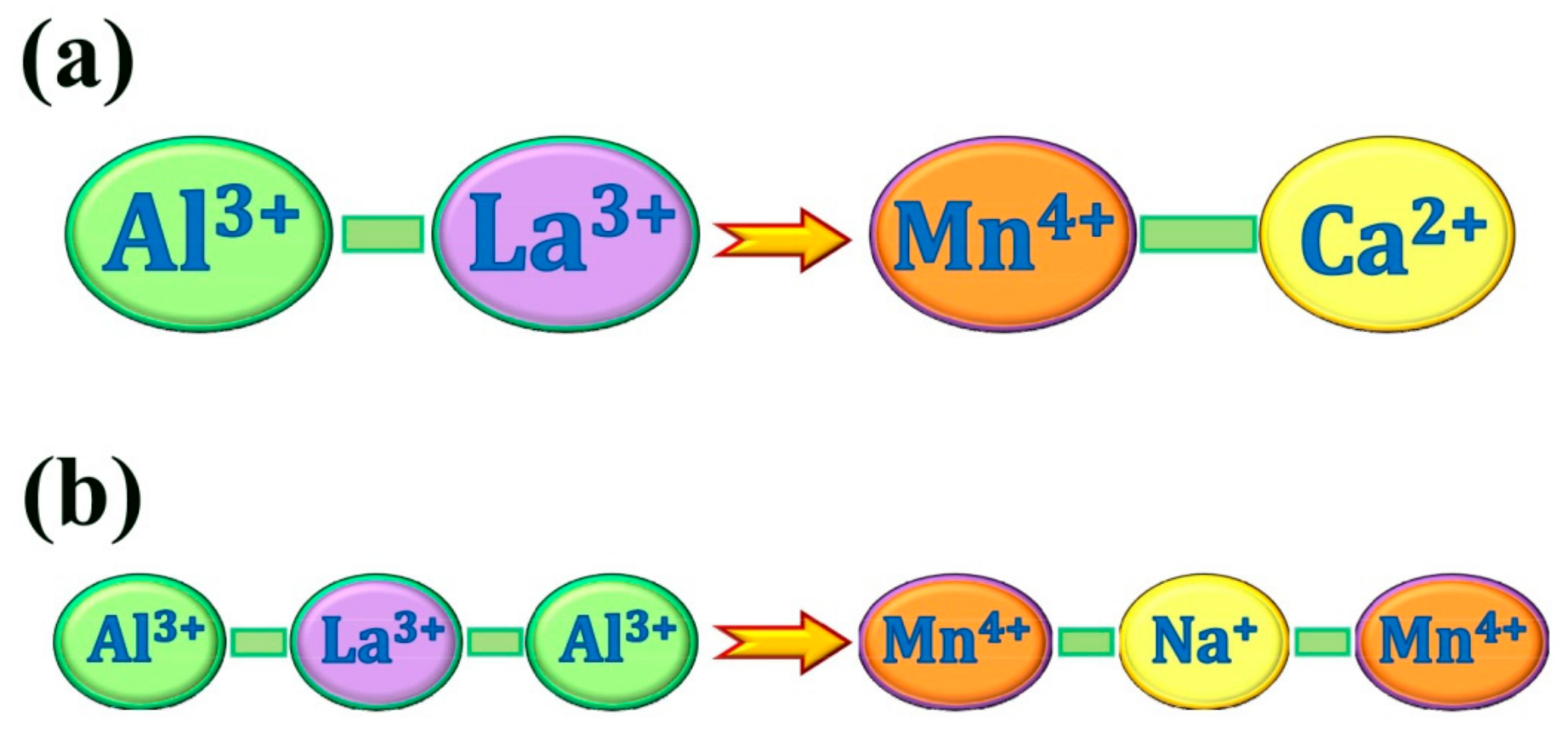
Figure 7.
Radius difference between doping ions and substitutable central ions. Blue stars are supposed to substitute on Al3+ site with coordination number VI and half-filled pink hexagons are supposed to substitute on La3+ site with coordination number XII. Stars and hexagons located in the green wireframe are feasible candidates for doping.
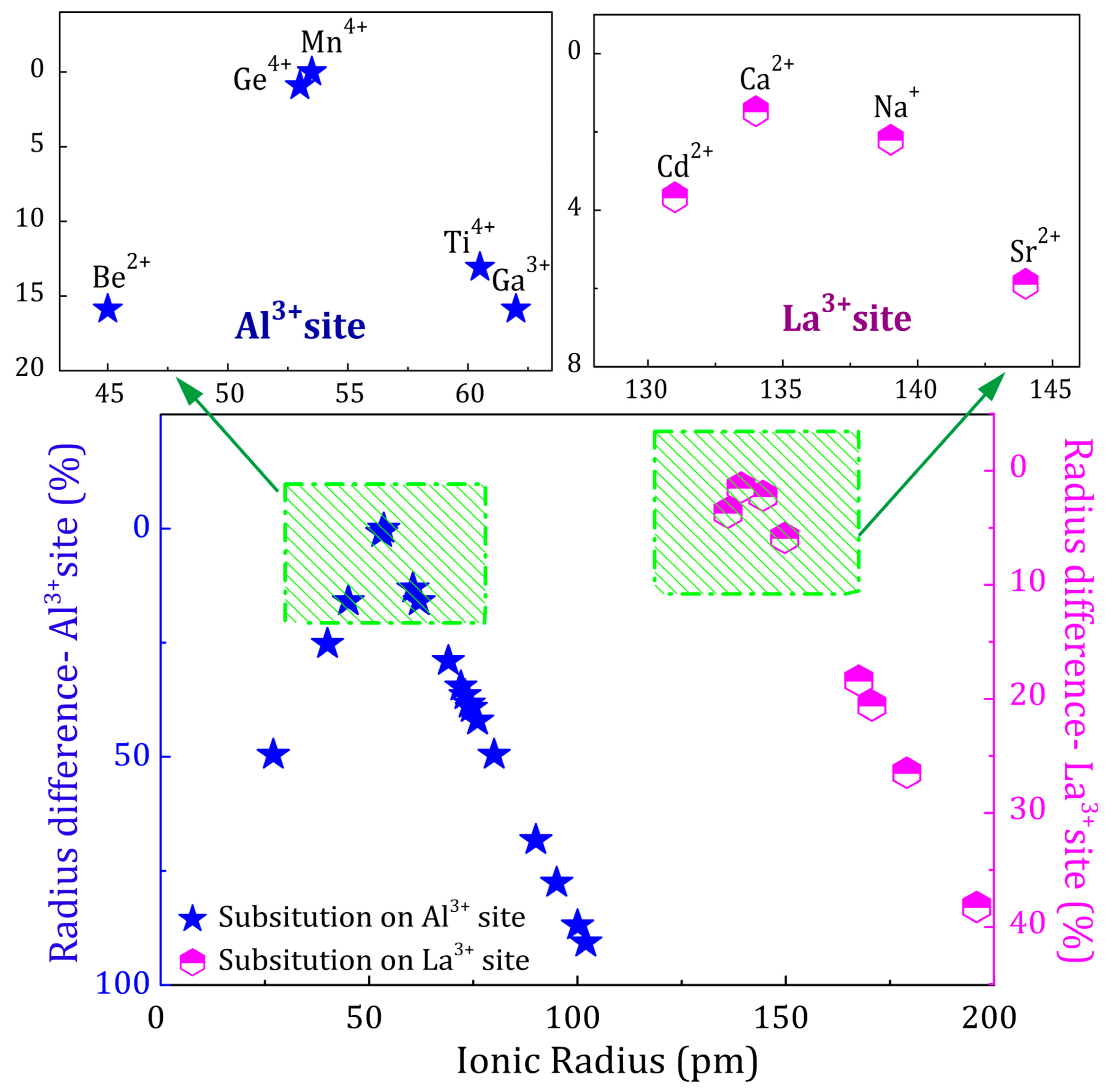
Figure 8.
A comparison of the time until the intensity of afterglow luminescence drops to 5 × 10⁻⁴ mW/sr/m2.The concentration of Mn4+ ion is 0.5% in each case and the concentration of R is 0.5%, 1%, 2%, 3% and 5% respectively from left to right in each doping group (R = Ca2+, Sr2+, Ba2+, Cl−, Na+, Ge4+). The first column corresponds to LaAlO3:0.5%Mn4+ as an intensity and duration benchmark of persistent luminescence.
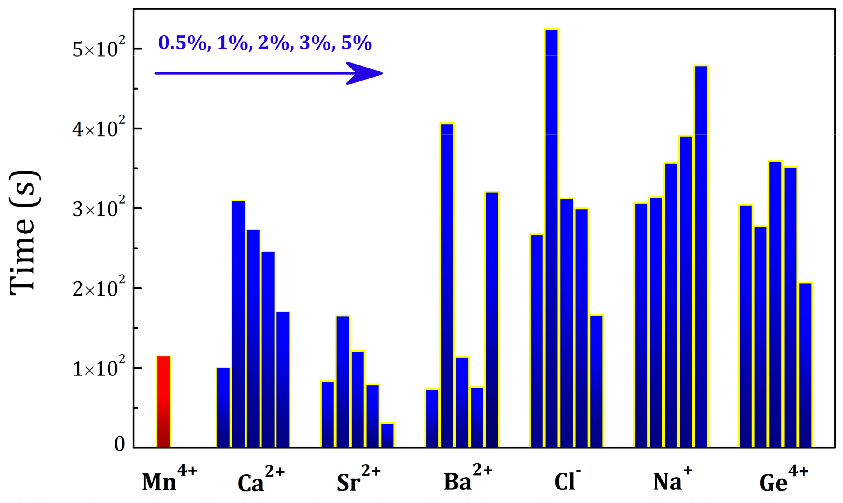
Figure 9.
A map of integral intensity of photoluminescence spectra from Mn4+/R (R = Ca2+, Sr2+, Ba2+, Cl−, Na+, Ge4+) co-dopants in the wavelength from 600 nm to 800 nm. The concentration of Mn4+ ions is 0.5% and the concentration of R is 0.5%, 1%, 2%, 3% and 5% respectively from left to right in each doping group.

© 2017 by the authors. Licensee MDPI, Basel, Switzerland. This article is an open access article distributed under the terms and conditions of the Creative Commons Attribution (CC BY) license (http://creativecommons.org/licenses/by/4.0/).
Share and Cite
MDPI and ACS Style
Du, J.; De Clercq, O.Q.; Korthout, K.; Poelman, D. LaAlO3:Mn4+ as Near-Infrared Emitting Persistent Luminescence Phosphor for Medical Imaging: A Charge Compensation Study. Materials 2017, 10, 1422. https://doi.org/10.3390/ma10121422
AMA Style
Du J, De Clercq OQ, Korthout K, Poelman D. LaAlO3:Mn4+ as Near-Infrared Emitting Persistent Luminescence Phosphor for Medical Imaging: A Charge Compensation Study. Materials. 2017; 10(12):1422. https://doi.org/10.3390/ma10121422
Chicago/Turabian StyleDu, Jiaren, Olivier Q. De Clercq, Katleen Korthout, and Dirk Poelman. 2017. "LaAlO3:Mn4+ as Near-Infrared Emitting Persistent Luminescence Phosphor for Medical Imaging: A Charge Compensation Study" Materials 10, no. 12: 1422. https://doi.org/10.3390/ma10121422
Note that from the first issue of 2016, this journal uses article numbers instead of page numbers. See further details here.