Effects of Annealing Conditions on Mixed Lead Halide Perovskite Solar Cells and Their Thermal Stability Investigation

 ,
,
Abstract
:1. Introduction
2. Experimental Section
2.1. Materials and Reagents
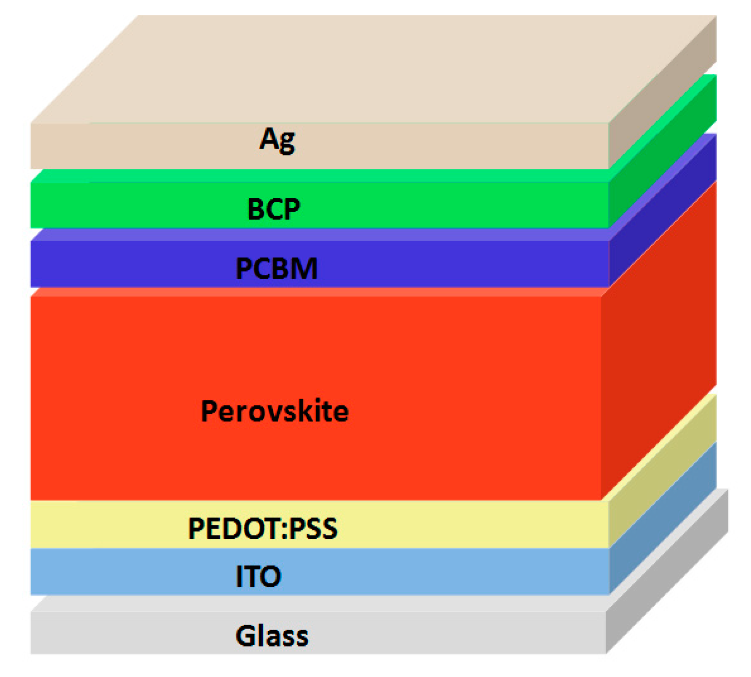
2.2. Fabrication of Perovskite Solar Cells
2.3. Characterization
3. Results and Discussion
4. Conclusions
Supplementary Materials
Acknowledgments
Author Contributions
Conflicts of Interest
References
- Ponseca, C.S.; Savenije, T.J.; Abdellah, M.; Zheng, K.; Yartsev, A.; Pascher, T.; Harlang, T.; Chabera, P.; Pullerits, T.; Stepanov, A.; et al. Organometal halide perovskite solar cell materials rationalized: Ultrafast charge generation, high and microsecond-long balanced mobilities, and slow recombination. J. Am. Chem. Soc. 2014, 136, 5189–5192. [Google Scholar] [CrossRef] [PubMed]
- Hao, F.; Stoumpos, C.C.; Chang, R.P.H.; Kanatzidis, M.G. Anomalous band gap behavior in mixed sn and pb perovskites enables broadening of absorption spectrum in solar cells. J. Am. Chem. Soc. 2014, 136, 8094–8099. [Google Scholar] [CrossRef] [PubMed]
- Stranks, S.D.; Eperon, G.E.; Grancini, G.; Menelaou, C.; Alcocer, M.J.P.; Leijtens, T.; Herz, L.M.; Petrozza, A.; Snaith, H.J. Electron-hole diffusion lengths exceeding 1 micrometer in an organometal trihalide perovskite absorber. Science 2013, 342, 341–344. [Google Scholar] [CrossRef] [PubMed]
- Chang, J.; Zhu, H.; Xiao, J.; Isikgor, F.H.; Lin, Z.; Hao, Y.; Zeng, K.; Xu, Q.-H.; Ouyang, J. Enhancing the planar heterojunction perovskite solar cell performance through tuning the precursor ratio. J. Mater. Chem. A 2016, 4, 7943–7949. [Google Scholar] [CrossRef]
- Kojima, A.; Teshima, K.; Shirai, Y.; Miyasaka, T. Organometal halide perovskites as visible-light sensitizers for photovoltaic cells. J. Am. Chem. Soc. 2009, 131, 6050–6051. [Google Scholar] [CrossRef] [PubMed]
- Bi, D.; Tress, W.; Dar, M.I.; Gao, P.; Luo, J.; Renevier, C.; Schenk, K.; Abate, A.; Giordano, F.; Correa Baena, J.-P.; et al. Efficient luminescent solar cells based on tailored mixed-cation perovskites. Sci. Adv. 2016, 2, 1–7. [Google Scholar] [CrossRef] [PubMed]
- Bi, D.; Yi, C.; Luo, J.; Décoppet, J.-D.; Zhang, F.; Zakeeruddin, S.M.; Li, X.; Hagfeldt, A.; Grätzel, M. Polymer-templated nucleation and crystal growth of perovskite films for solar cells with efficiency greater than 21%. Nat. Energy 2016, 1, 16142. [Google Scholar] [CrossRef]
- Meng, L.; You, J.; Guo, T.-F.; Yang, Y. Recent advances in the inverted planar structure of perovskite solar cells. Acc. Chem. Res. 2016, 49, 155–165. [Google Scholar] [CrossRef] [PubMed]
- Jung, H.S.; Park, N.-G. Perovskite solar cells: From materials to devices. Small 2015, 11, 10–25. [Google Scholar] [CrossRef] [PubMed]
- Docampo, P.; Ball, J.M.; Darwich, M.; Eperon, G.E.; Snaith, H.J. Efficient organometal trihalide perovskite planar-heterojunction solar cells on flexible polymer substrates. Nat. Commun. 2013, 4, 2761–2767. [Google Scholar] [CrossRef]
- You, J.; Yang, Y.; Hong, Z.; Song, T.-B.; Meng, L.; Liu, Y.; Jiang, C.; Zhou, H.; Chang, W.-H.; Li, G.; et al. Moisture assisted perovskite film growth for high performance solar cells. Appl. Phys. Lett. 2014, 105, 183902. [Google Scholar] [CrossRef]
- Yang, H.; Zhang, J.; Zhang, C.; Chang, J.; Lin, Z.; Chen, D.; Sun, X.; Xi, H.; Han, G.; Hao, Y. Effect of polyelectrolyte interlayer on efficiency and stability of p-i-n perovskite solar cells. Sol. Energy 2016, 139, 190–198. [Google Scholar] [CrossRef]
- Chang, J.; Zhu, H.; Li, B.; Isikgor, F.H.; Hao, Y.; Xu, Q.; Ouyang, J. Boosting the performance of planar heterojunction perovskite solar cell by controlling the precursor purity of perovskite materials. J. Mater. Chem. A 2016, 4, 887–893. [Google Scholar] [CrossRef]
- Chang, J.; Lin, Z.; Zhu, H.; Isikgor, F.H.; Xu, Q.-H.; Zhang, C.; Hao, Y.; Ouyang, J. Enhancing the photovoltaic performance of planar heterojunction perovskite solar cells by doping the perovskite layer with alkali metal ions. J. Mater. Chem. A 2016, 4, 16546–16552. [Google Scholar] [CrossRef]
- Sun, X.; Zhang, C.; Chang, J.; Yang, H.; Xi, H.; Lu, G.; Chen, D.; Lin, Z.; Lu, X.; Zhang, J.; et al. Mixed-solvent-vapor annealing of perovskite for photovoltaic device efficiency enhancement. Nano Energy 2016, 28, 417–425. [Google Scholar] [CrossRef]
- Eperon, G.E.; Stranks, S.D.; Menelaou, C.; Johnston, M.B.; Herz, L.M.; Snaith, H.J. Formamidinium lead trihalide: A broadly tunable perovskite for efficient planar heterojunction solar cells. Energy Environ. Sci. 2014, 7, 982–988. [Google Scholar] [CrossRef]
- Sheng, R.; Ho-Baillie, A.; Huang, S.; Chen, S.; Wen, X.; Hao, X.; Green, M.A. Methylammonium lead bromide perovskite-based solar cells by vapor-assisted deposition. J. Phys. Chem. C 2015, 119, 3545–3549. [Google Scholar] [CrossRef]
- Yang, W.S.; Noh, J.H.; Jeon, N.J.; Kim, Y.C.; Ryu, S.; Seo, J.; Seok, S.I. High-performance photovoltaic perovskite layers fabricated through intramolecular exchange. Science 2015, 348, 1234–1237. [Google Scholar] [CrossRef] [PubMed]
- Jeon, N.J.; Noh, J.H.; Yang, W.S.; Kim, Y.C.; Ryu, S.; Seo, J.; Seok, S.I. Compositional engineering of perovskite materials for high-performance solar cells. Nature 2015, 517, 476–480. [Google Scholar] [CrossRef] [PubMed]
- Jesper Jacobsson, T.; Correa-Baena, J.-P.; Pazoki, M.; Saliba, M.; Schenk, K.; Gratzel, M.; Hagfeldt, A. Exploration of the compositional space for mixed lead halogen perovskites for high efficiency solar cells. Energy Environ. Sci. 2016, 9, 1706–1724. [Google Scholar] [CrossRef]
- Yang, Z.; Chueh, C.-C.; Liang, P.-W.; Crump, M.; Lin, F.; Zhu, Z.; Jen, A.K.Y. Effects of formamidinium and bromide ion substitution in methylammonium lead triiodide toward high-performance perovskite solar cells. Nano Energy 2016, 22, 328–337. [Google Scholar] [CrossRef]
- Chen, W.; Wu, Y.; Liu, J.; Qin, C.; Yang, X.; Islam, A.; Cheng, Y.-B.; Han, L. Hybrid interfacial layer leads to solid performance improvement of inverted perovskite solar cells. Energy Environ. Sci. 2015, 8, 629–640. [Google Scholar] [CrossRef]
- Yan, W.; Li, Y.; Sun, W.; Peng, H.; Ye, S.; Liu, Z.; Bian, Z.; Huang, C. High-performance hybrid perovskite solar cells with polythiophene as hole-transporting layer via electrochemical polymerization. RSC Adv. 2014, 4, 33039–33046. [Google Scholar] [CrossRef]
- Lin, Z.; Chang, J.; Xiao, J.; Zhu, H.; Xu, Q.-H.; Zhang, C.; Ouyang, J.; Hao, Y. Interface studies of the planar heterojunction perovskite solar cells. Sol. Energy Mater. Sol. Cells 2016, 157, 783–790. [Google Scholar] [CrossRef]
- Jeon, N.J.; Noh, J.H.; Kim, Y.C.; Yang, W.S.; Ryu, S.; Seok, S.I. Solvent engineering for high-performance inorganic–organic hybrid perovskite solar cells. Nat. Mater. 2014, 13, 897–903. [Google Scholar] [CrossRef] [PubMed]
- Roldan-Carmona, C.; Gratia, P.; Zimmermann, I.; Grancini, G.; Gao, P.; Graetzel, M.; Nazeeruddin, M.K. High efficiency methylammonium lead triiodide perovskite solar cells: The relevance of non-stoichiometric precursors. Energy Environ. Sci. 2015, 8, 3550–3556. [Google Scholar] [CrossRef]
- Chen, Q.; Zhou, H.; Song, T.-B.; Luo, S.; Hong, Z.; Duan, H.-S.; Dou, L.; Liu, Y.; Yang, Y. Controllable self-induced passivation of hybrid lead iodide perovskites toward high performance solar cells. Nano Lett. 2014, 14, 4158–4163. [Google Scholar] [CrossRef] [PubMed]
- Zuo, L.; Gu, Z.; Ye, T.; Fu, W.; Wu, G.; Li, H.; Chen, H. Enhanced photovoltaic performance of ch3nh3pbi3 perovskite solar cells through interfacial engineering using self-assembling monolayer. J. Am. Chem. Soc. 2015, 137, 2674–2679. [Google Scholar] [CrossRef] [PubMed]
- Yang, B.; Dyck, O.; Poplawsky, J.; Keum, J.; Puretzky, A.; Das, S.; Ivanov, I.; Rouleau, C.; Duscher, G.; Geohegan, D.; et al. Perovskite solar cells with near 100% internal quantum efficiency based on large single crystalline grains and vertical bulk heterojunctions. J. Am. Chem. Soc. 2015, 137, 9210–9213. [Google Scholar] [CrossRef] [PubMed]
- Dang, Y.; Liu, Y.; Sun, Y.; Yuan, D.; Liu, X.; Lu, W.; Liu, G.; Xia, H.; Tao, X. Bulk crystal growth of hybrid perovskite material CH3NH3PbI3. CrystEngComm 2015, 17, 665–670. [Google Scholar] [CrossRef]
- Ying, C.; Shi, C.; Wu, N.; Zhang, J.; Wang, M. A two-layer structured pbi2 thin film for efficient planar perovskite solar cells. Nanoscale 2015, 7, 12092–12095. [Google Scholar] [CrossRef] [PubMed]
- Rong, Y.; Venkatesan, S.; Guo, R.; Wang, Y.; Bao, J.; Li, W.; Fan, Z.; Yao, Y. Critical kinetic control of non-stoichiometric intermediate phase transformation for efficient perovskite solar cells. Nanoscale 2016, 8, 12892–12899. [Google Scholar] [CrossRef] [PubMed]
- Das, S.; Yang, B.; Gu, G.; Joshi, P.C.; Ivanov, I.N.; Rouleau, C.M.; Aytug, T.; Geohegan, D.B.; Xiao, K. High-performance flexible perovskite solar cells by using a combination of ultrasonic spray-coating and low thermal budget photonic curing. ACS Photonics 2015, 2, 680–686. [Google Scholar] [CrossRef]
- Hailong, Y.; Junchi, Z.; Chunfu, Z.; Zhenhua, L.; Dazheng, C.; Jingjing, C.; Jincheng, Z. Efficient flexible inverted small-bandgap organic solar cells with low-temperature zinc oxide interlayer. Jpn. J. Appl. Phys. 2016, 55, 122302. [Google Scholar]


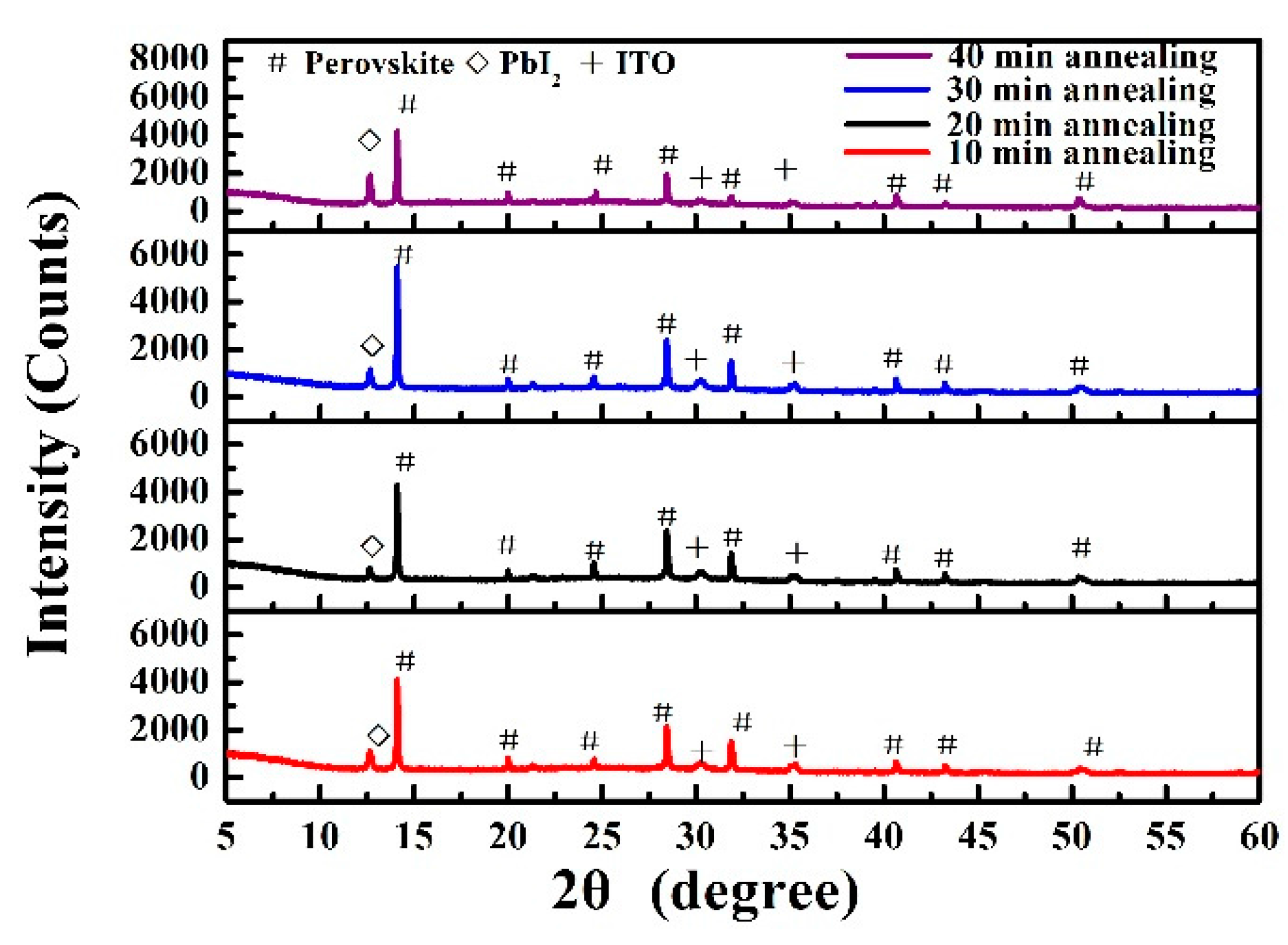
| Annealing Time (min) | JSC (mA/cm2) | VOC (V) | FF (%) | PCE (%) | Best PCE (%) |
|---|---|---|---|---|---|
| 10 | 17.84 ± 1.27 | 1.02 ± 0.01 | 69.92 ± 4.09 | 12.65 ± 0.50 | 13.30 |
| 20 | 18.01 ± 0.69 | 0.98 ± 0.01 | 78.41 ± 1.18 | 13.83 ± 0.73 | 14.63 |
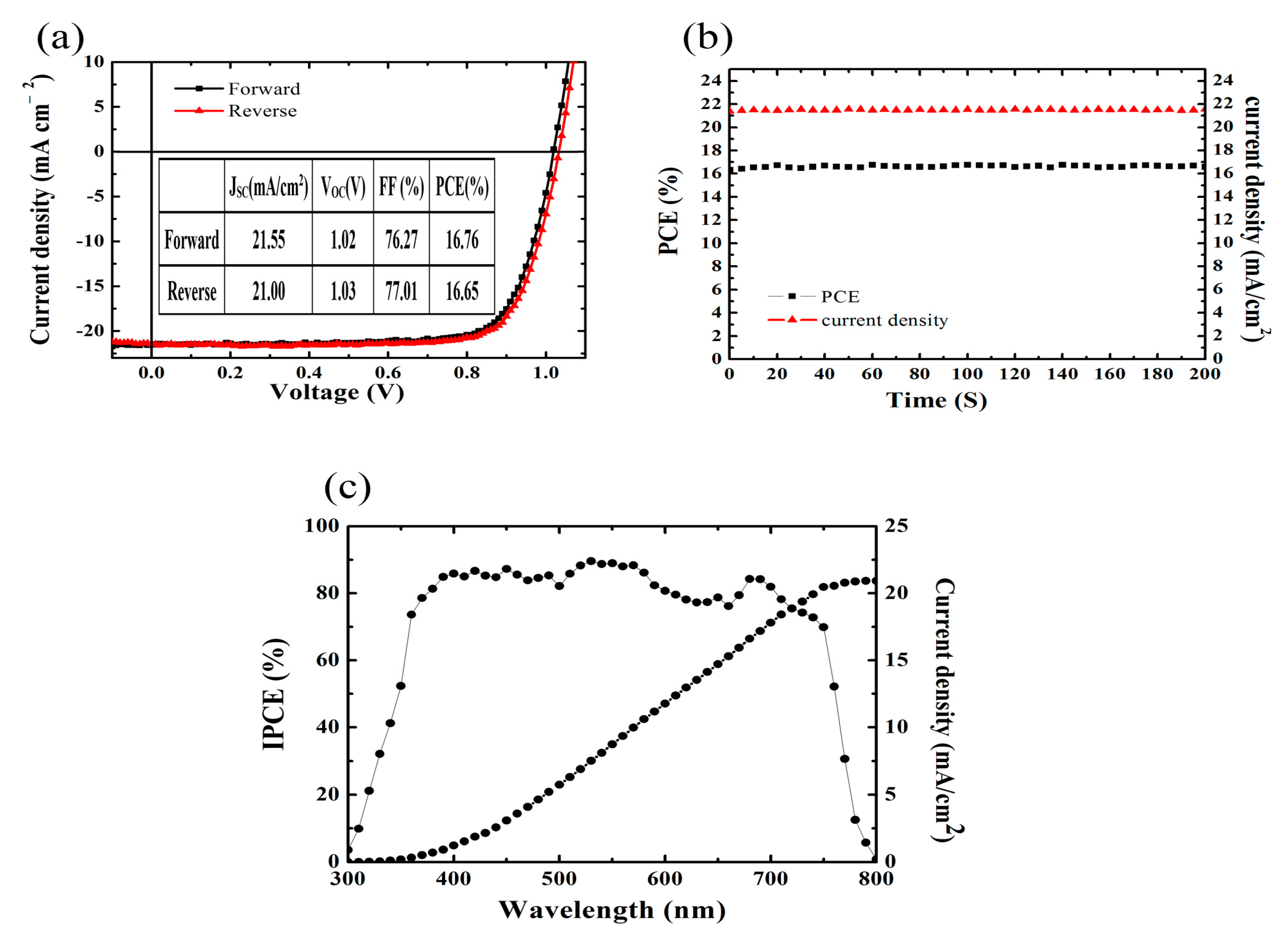
| 30 | 20.12 ± 0.91 | 0.99 ± 0.03 | 78.67 ± 2.93 | 15.70 ± 0.62 | 16.76 |
| 40 | 18.17 ± 0.74 | 0.96 ± 0.01 | 77.52 ± 5.17 | 13.53 ± 0.71 | 14.30 |
| Devices | JSC (mA/cm2) | VOC (V) | FF (%) | PCE (%) | |
|---|---|---|---|---|---|
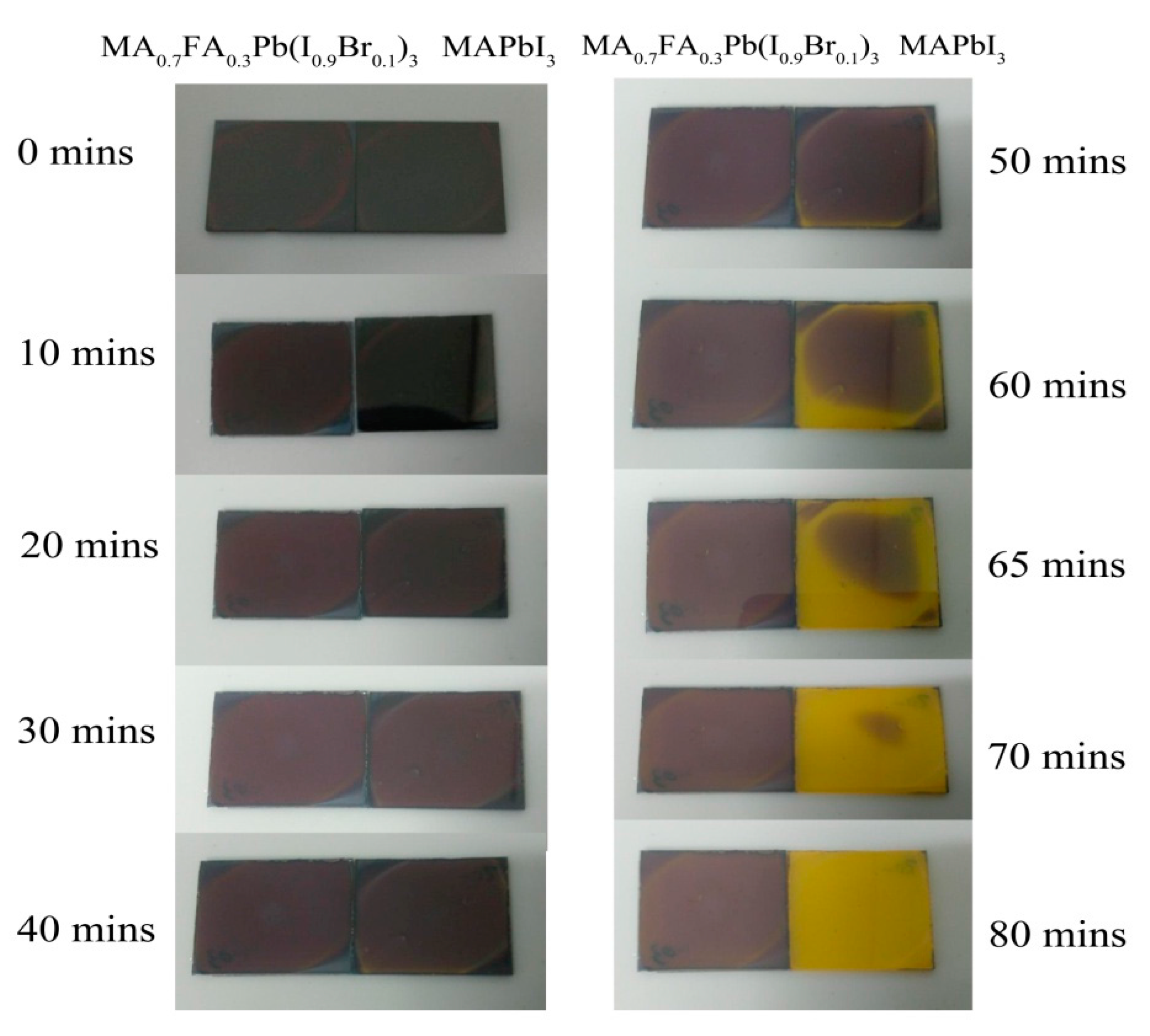
| MAPbI3 Solar cells | initial | 19.30 ± 0.25 | 0.99 ± 0.01 | 73.33 ± 0.64 | 13.96 ± 0.17 |
| 24 h heated at 80 °C | 12.56 ± 1.09 | 0.98 ± 0.02 | 53.15 ± 6.34 | 6.50 ± 0.17 | |
| MA0.7FA0.3Pb(I0.9Br0.1)3 Solar Cells | initial | 20.10 ± 0.95 | 1.00 ± 0.03 | 78.86 ± 2.49 | 15.76 ± 0.63 |
| 24 h heated at 80 °C | 16.40 ± 0.48 | 0.98 ± 0.01 | 68.68 ± 1.88 | 11.03 ± 0.15 | |
© 2017 by the authors. Licensee MDPI, Basel, Switzerland. This article is an open access article distributed under the terms and conditions of the Creative Commons Attribution (CC BY) license (http://creativecommons.org/licenses/by/4.0/).
Share and Cite
Yang, H.; Zhang, J.; Zhang, C.; Chang, J.; Lin, Z.; Chen, D.; Xi, H.; Hao, Y. Effects of Annealing Conditions on Mixed Lead Halide Perovskite Solar Cells and Their Thermal Stability Investigation. Materials 2017, 10, 837. https://doi.org/10.3390/ma10070837
Yang H, Zhang J, Zhang C, Chang J, Lin Z, Chen D, Xi H, Hao Y. Effects of Annealing Conditions on Mixed Lead Halide Perovskite Solar Cells and Their Thermal Stability Investigation. Materials. 2017; 10(7):837. https://doi.org/10.3390/ma10070837
Chicago/Turabian StyleYang, Haifeng, Jincheng Zhang, Chunfu Zhang, Jingjing Chang, Zhenhua Lin, Dazheng Chen, He Xi, and Yue Hao. 2017. "Effects of Annealing Conditions on Mixed Lead Halide Perovskite Solar Cells and Their Thermal Stability Investigation" Materials 10, no. 7: 837. https://doi.org/10.3390/ma10070837