Fabrication and Anti-Oxidation Ability of SiC-SiO2 Coated Carbon Fibers Using Sol-Gel Method

Department of Materials Science and Engineering, Wuhan University of Technology, Wuhan 430070, China
*
Author to whom correspondence should be addressed.
Materials 2018, 11(3), 350; https://doi.org/10.3390/ma11030350
Submission received: 21 January 2018
/
Revised: 23 February 2018
/
Accepted: 23 February 2018
/
Published: 27 February 2018
Abstract
:The paper proposed a method to improve the anti-oxidation performance of carbon fibers (CF) at high temperature environment by coating silicon dioxide (SiO2) and silicon carbide (SiC). The modified sol-gel method had been used to ensure the proper interface between fibers and coating. We used polydimethylsiloxane and ethyl orthosilicate to make stable emulsion to uniformly disperse SiC nanoparticles. The modified SiO2/SiC coating had been coated on CF successfully. Compared with the untreated CF, the coated fibers started to be oxidized around 900 °C and the residual weight was 57% at 1400 °C. The oxidation mechanism had been discussed. The structure of SiC/SiO2 coated CF had been characterized by scanning electron microscope and X-ray diffraction analysis. Thermal gravimetric analysis was used to test the anti-oxidation ability of CF with different coatings.
1. Introduction
Since the 1960s, carbon fibers (CF) have been widely used in various fields due to its high specific modulus, corrosion resistance and electrical conductivity as well as other unique properties. Instead of using CF alone, people tend to combine it with different matrices to obtain composites that own excellent strength, low thermal expansion coeffient, and lightweight [1,2,3]. In the aerospace area, some parts of planes, spaceships, and some parts of rocket need to resist extremely high temperature. For example, the rocket fairing is used to protect the rocket and the satellite from damages caused by heat out of its friction in the atmosphere. Traditional ultra-high temperature protection materials contain refractory metal, ceramic composites, et cetera [4]. They were either too heavy, or the mechanical properties were not very good. CF reinforced composites have great potential to replace them because of lightweight, high-strength and flexibility. The rocket fairing of Titan rocket (USA) was made from carbon fibers, epoxy resin, and aluminum honeycomb. However, CF has poor oxidation resistance in the air environment at high temperature. It is important to improve the anti-oxidation ability of CF to extent its application to make thermal protection parts with excellent mechanical properties.
Shielding is an effective method to increase the oxidation resistance ability of CF. It can prevent CF substrate from contacting the oxygen directly. The type of coating can be various, such as metal coating (Zn, Ni, Cu, Ti, Zr, Ag); oxides coating (SiO2, Fe3O4, Al2O3, TiO2), nitrides coating (BN, TiN), carbides coating (SiC, TiC, TaC, ZrC, B4C), and composite coating (Al2O3/Y2O3, ZrC–ZrB2–SiC, SiBNC) [5,6,7,8,9,10,11,12,13,14,15,16]. Among them, ceramic coatings are the most promising coatings due to the fact that they are much lighter and have better wettability, which can reduce interface diffusion and reaction.
The common ways to fabricate ceramic coatings are vapor deposition, precursor infiltration, and pyrolysis (PIP), and sol-gel method [17,18,19]. The chemical or physical vapor deposition can produce uniform and dense coatings. Moreover, plasma treatment has been used in vapor deposition, which can deposit homogeneous, well-adhesive coatings at lower temperature on different substrates [20,21]. To improve the surface roughness, structure, and mechanical properties of CF, hydrogen and oxygen plasma treatments are applied. The density of functional groups and changes in the carbon bonding contributed to the enhancement of the adhesion to PEI matrix [22]. Both the morphology and the structure of coatings are controllable. But, the low deposition rate and the uneconomical cost make vapor deposition not always practical [23]. In PIP, polycarbosilane (PCS) and polysilazane (PSZ) are often used as precursor to make SiC coating. However, it is hard for the polymer precursor to synthesize because of the complex process [24,25]. Sol-gel method is a much more practical and feasible way to fabricate three-dimensional (3D) composite coating. Besides, the cost of Sol-gel method is quite economical, and the coating has a low densification temperature (<1000 °C) and low shrinkage, which can reduce drying stress between coatings and matrix. Some reseachers [26,27,28,29] mentioned that the tetraethylorthosilicate (TEOS), vinyltriethoxysilane (VTES) and ethyl alcohol (EtOH) could be used as raw materials to fabricate SiO2 coating by sol-gel method. However, the best decomposition temperature they have got is around 800 °C. When the temperature is over 600 °C, the weight loss is more than 50%. The anti-oxidation performance of silicon materials coated CF still has great potential to improve.
To lower the formation temperature and to improve the anti-oxidation performance of CF, modified sol-gel method has been proposed in this paper. The best ratio of TEOS/water has been discussed. The mechanism of oxidation process and the properties of coated CF at different temperature environment have been investigated.
2. Experiment
2.1. Preparation of Modified SiC/SiO2 Sol and Emulstion
To remove the protective polymer layer of CF (Wuxi Weppom Composite Materials Company, Wuxi, China), the fibers were heated at 400 °C for 1 h under the nitrogen atmosphere. Then, put the CF into 75 wt % nitric acid (Shanghai Aladdin Reagent Factory, Shanghai, China) with ultrasonic treatment for 1 h at 60 °C.
In order to explore the optimum proportion of sol, four different samples were prepared under different ratio of raw materials. The samples had been marked as samples 1–4 with the ratio of ethanol (Sinopharm Chemical Reagent Company, Shanghai, China), distilled water and TEOS (Shanghai Aladdin Reagent Factory) being 5:1:1, 5:1:3, 5:1:5, 5:1:7, respectively. Hydrochloric acid had been used to adjust pH to 3. After stirring the solution for 2 h, the sol had been stood for 10 h at 60 °C to obtain transparent SiO2 sol.
To disperse SiC nanoparticles (50nm, Shanghai Aladdin Reagent Factory) uniformly, homogenizer (15,000 rpm) was used to prepare SiO2 emulsion. The polydimethylsiloxane (Shanghai Aladdin Reagent Factory, ~10 mPa.s, neat, s104472), SiO2 sol and distilled water were mixed with the ratio 1:1:1. 5 wt % tween 80 (T104866, Shanghai Aladdin Reagent Factory) had been added into the mixture as emulsifier. When the SiO2 emulsion became stable, SiC nanoparticles were dispersed into the emulsion (24 g/200 mL) uniformly.
2.2. Coating Process
CF was immersed into the SiC/SiO2 emulsion separately. After 30 min ultrasonic treatment, the fiber was pulled out from the sol (10 mm/min) and heated to 600 °C (5 °C/min) in argon flow (40 mL/min). After 30 min preservation, the temperature increased to 1200 °C with a rate of 4 °C/min. Before naturally cooling down to the room temperature, the sample was preserved at 1200 °C for 120 min. Then, repeat the above steps 3 times to increase the thickness of coating.
2.3. Oxidation
In order to explore the mechanism of oxidation process, SiC/SiO2 coated CF samples were treated at 800 °C, 1000 °C and 1400 °C for 15 min in the air environment. To evaluate the influence of thermal shock, the samples were put back to room temperature and cooled down naturally.
2.4. Characterization
The surface morphology of coated CF and oxidized samples were characterized by a JSM-7800FPRIME Scanning Electron Microscope (SEM) (JEOL, Tokyo, Japan). To analyze the crystal structure of unoxidized coating and 1400 °C treated coating, the X-Ray diffraction (XRD) analysis (D8 Advance X-ray diffract meter, Bruker Corporation, Ettlingen, Germany) was used. The scanning was conducted from 2θ angle of 5°–80° at a scan rate of 5°/min. The NETZSCH STA 449 F3 typed thermal analyzer (NETZSCH, Selb, Germany) was applied to Thermal Gravimetric (TG) analysis. It can test the anti-oxidation performance of each sample (both uncoated CF and SiC/SiO2 coated CF) under the air atmosphere with a constant heating rate of 5 °C/min from 25 °C to 1300 °C.
To test the mechanical property of CF, 10 samples were prepared by the method in this patent [30]. First, CF had been fixed at two sides of a frame. Then, the frame was immersed into 40 wt % epoxy resin for 5 min. After drying at 110–130 °C, the CF was tested through the Instron testing machine (model-5866, Instron Pty Ltd, Norwood, MA, USA). The testing process was followed by the ISO standard [31]. The tensile strength was calculated by the equation:
σ—tensile strength (MPa); P—failure load (N); ρ—the density of CF (kg/m3); t—linear density of CF (kg/m).
The Young’s modulus was calculated by the equation:
E—Young’s modulus (GPa); ΔP—The change of load value (N); ρ—the density of CF (kg/m3); t—linear density of CF (kg/m); L—the length of the sample (mm); and, ΔL—The change of length of the sample (mm).
The fracture elongation was calculated by the equation:
Ɛ—the fracture of elongation; L—the length of the sample (mm); ΔLb—elongation at break.
3. Result and Discussion
3.1. Microstructure Analysis of Coatings
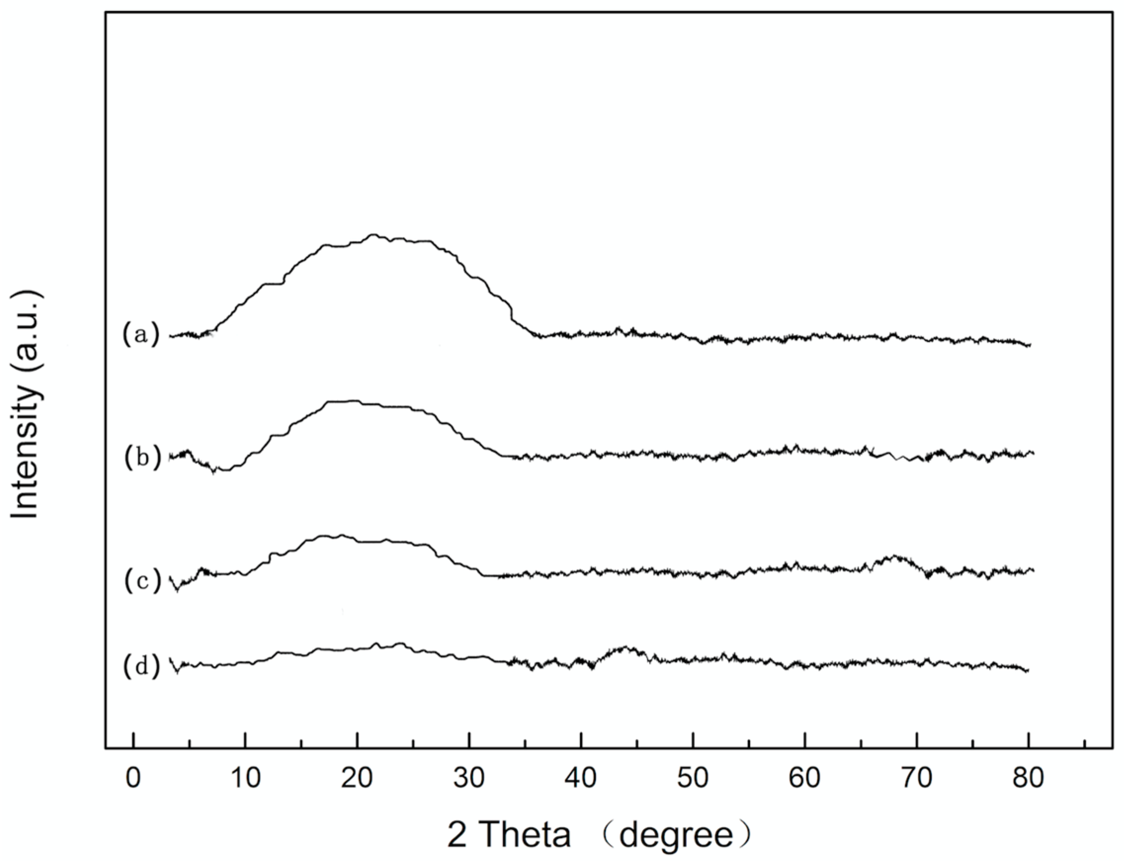
Table 1 presents the coating properties of different water/TEOS ratio. Figure 1 shows that the XRD diffraction patters of coating between 15° and 30° is wide. It can be deduced that the main component of the coating is amorphous SiO2. The curve of line (a) is wider and more obvious than other three lines. It means that the formation rate is the fastest with the ratio 1/3. When combined with the appearance and performance results that were shown in Table 1, it can certify that best water/TEOS ratio to fabricate SiO2 coating is 1/3. The main reactions of the sol-gel system were as follows.
Hydrolytic reaction:
Condensation reaction:
Polymerization:
![Materials 11 00350 i001]()

Among them, R stands for –C2H5. The products of the reactions are colloidal particles with different size and structure. A three-dimentional network of xerogel can be produced after dehydration. The property of xerogel is related to the temperature, solvent, pH and the ration of water and TEOS. TEOS cannot dissolve in water, but it can dissolve in EtOH and react with water in it. When the water is much more than the TEOS, it will take a long time to form sol. Instead, when the water is much less than the TEOS, sol can be form very quickly (less than 40 min). However, the stability of such sol is poor, and stratification could happen in the few hours. So, the SiO2 sol was prepared with the best water/TEOS ratio.
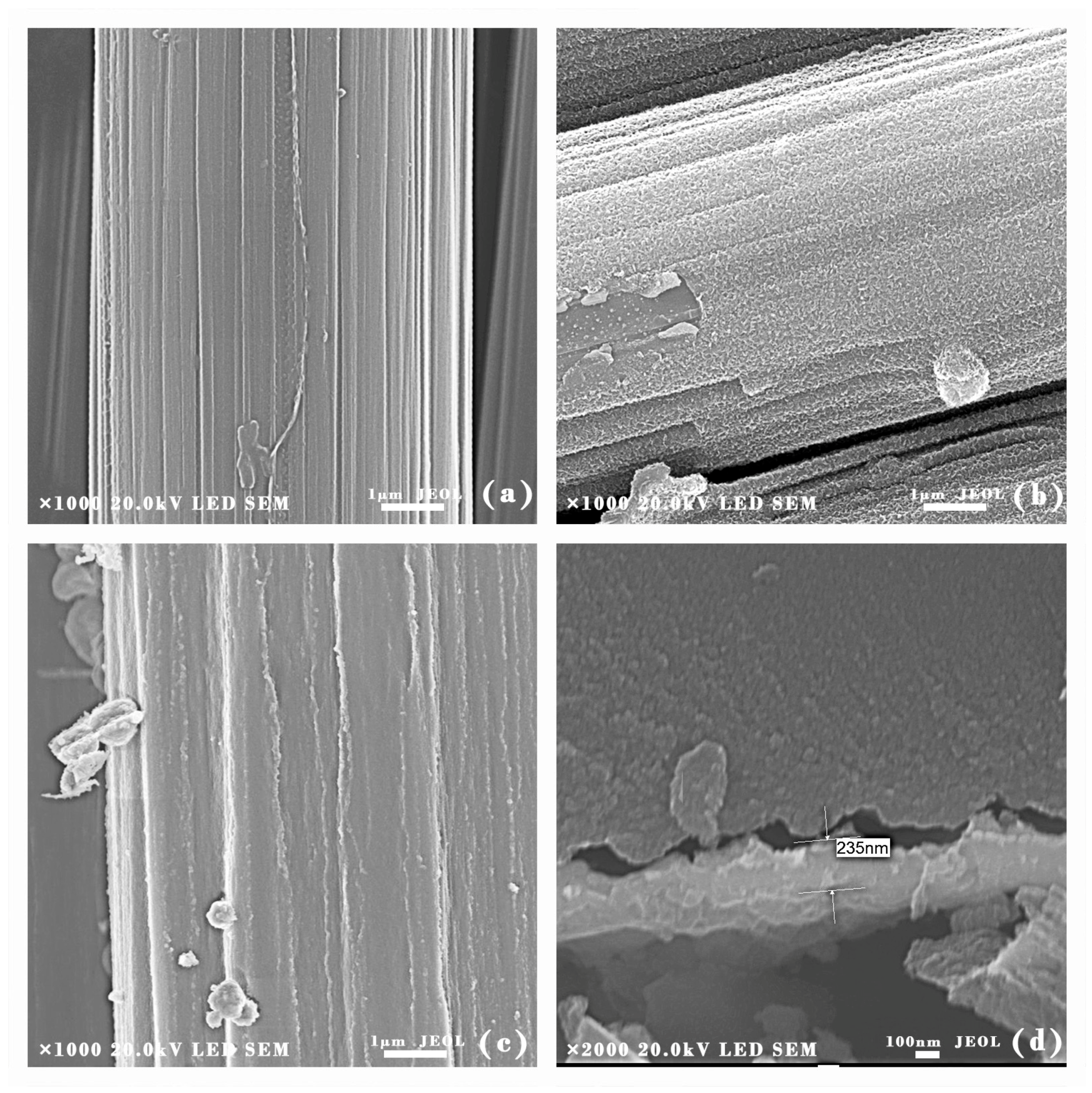
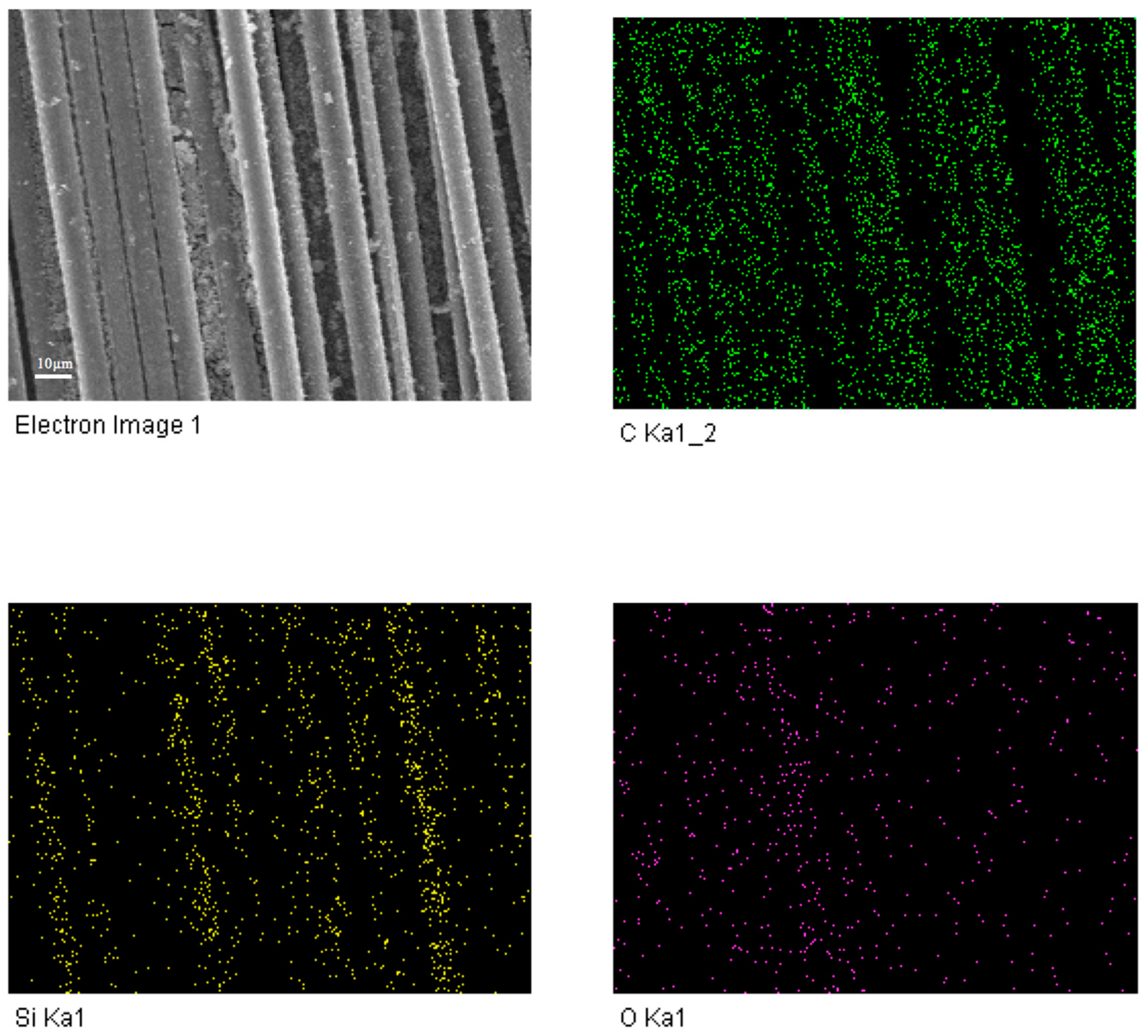
To analyze the surface morphology of the coatings, SEM experiments were conducted on uncoated CF and SiO2 coated CF. Figure 2a shows that the grooves were formed at the surface of uncoated CF. Because, after removing the protective layer of CF, concentrated nitric acid could increase the surface roughness and specific area of CF, enhancing the interface effect between SiO2 coating and CF. The generation of carboxylic acids, hydroxyl groups, and lactones functionalities contributed to the increasing of adhesion strength [32]. Figure 2b presents the surface morphology of SiO2 coated CF. Since the SiO2 coating had covered the grooves; the surface of CF was uniform and smooth. However, some aggregations could be seen at the surface of the coating, since the emulsion particles were aggregated and may not spread uniformly before the heating process. SiC/SiO2 coated CF are shown in Figure 1c. The SiC nanoparticles had been coated onto CF successfully. The surface of SiC/SiO2 coated CF was rough and laminar. There were some small bulges that were spreading along the CF as the SiC nanoparticles had been embedded into SiO2 coating. Figure 2d was the cross-section morphology of coated CF. The coating was compact and uniform. Displacement can be found at the interface between coating and CF. The coating had been moved to the left side of the picture because of the external force when the CF was cut off. The protrusion and concave can fit together on the whole. Therefore, it can be deduced that the coating was originally attached on CF closely. It can be found that the coating was compact and uniform. The whole coating is about 0.23 μm in thickness, and there was little aggregation at the surface of the coating. Energy Dispersive Spectroscopy (EDS) analysis had been used to further analyze the elements distribution of composite coating. Figure 3 shows that Si, O, and C were dispersed evenly on the surface of the fiber. Because of the existence of SiC nanoparticles, O element was not as concentrated as Si and C elements.
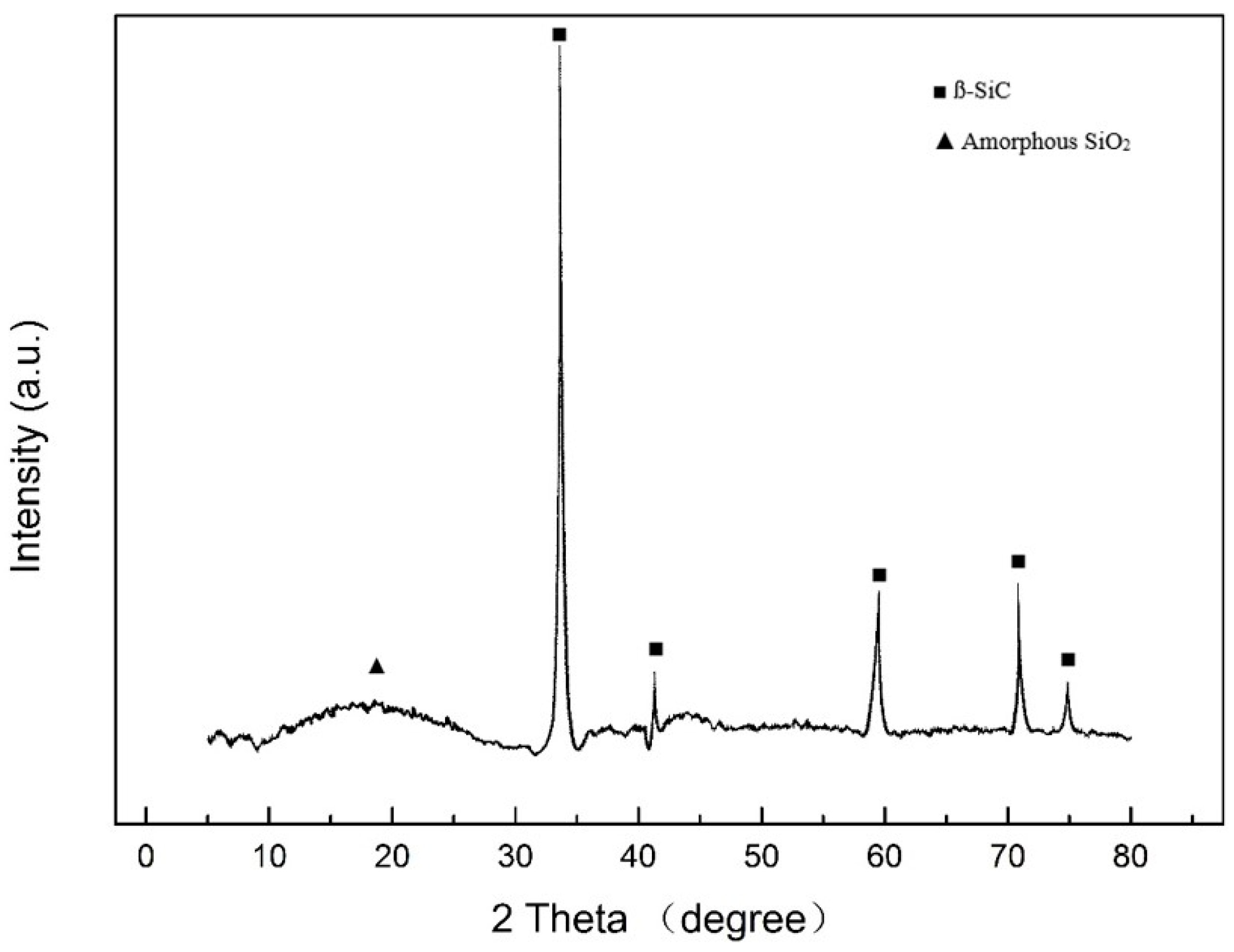
Figure 4 shows the band diffraction peaks of SiC/SiO2 coated CF. Around 2θ = 22°, the peak was broad and wide, which reflects the existence of amorphous SiO2. The formation temperature is not high enough to make SiO2 emusltion to transit to crystal. At 35°, 41°, 60°, and 71°, the diffraction peaks were corresponded to the ß-SiC. On the one hand, it proves that SiC nanoparticles had embedded into the coating successfully; on the other hand, it can extrapolate that the nanoparticles and the coating only had physical bonding instead of chemical reactions.
3.2. Mechanical Property of Coated CF
The mechanical property was tested following the method described in reference [30,31]. The results were shown in the Table 2. It could be observed that there are little differences in the mechanical property of coated CF and uncoated CF as coating only affected the roughness of CF’s surface, because the coating only affected the roughness of CF’s surface. From the XRD analysis (Figure 4), it proves that the interfacial bonding between the coating and CF is physical bonding. The strength of ceramic is higher than CF. Besides, the ceramic coating may cover some surface defects and limit their influence on the crack initiation [33]. So, before oxidation, the coated CF owned higher strength than the uncoated CF. When the temperature was at 800 °C, the mechanical property of coated CF only decreased 15%. However, when the temperature was at 1000 °C, the mechanical property of coated CF decreased rapidly, especially the modulus. Since the coating was partly damaged and the stiffness of coated CF had been reduced, it became much easier for the fiber to be deformed by external force. While the temperature was over 1400 °C, the fibers became soft and brittle. CF had been seriously damaged and the cracks of the coating could be seen directly at the surface of CF. The mechanical property of coated fibers slumped quickly. Based on the above results, the mechanical property of SiC/SiO2 coated CF will decrease after oxidation. However, when the temperature was lower than 1400 °C, the strength and the modulus of coated CF were in the acceptable range so the CF could stay in the right shape.
3.3. Anti-Oxidation Performance
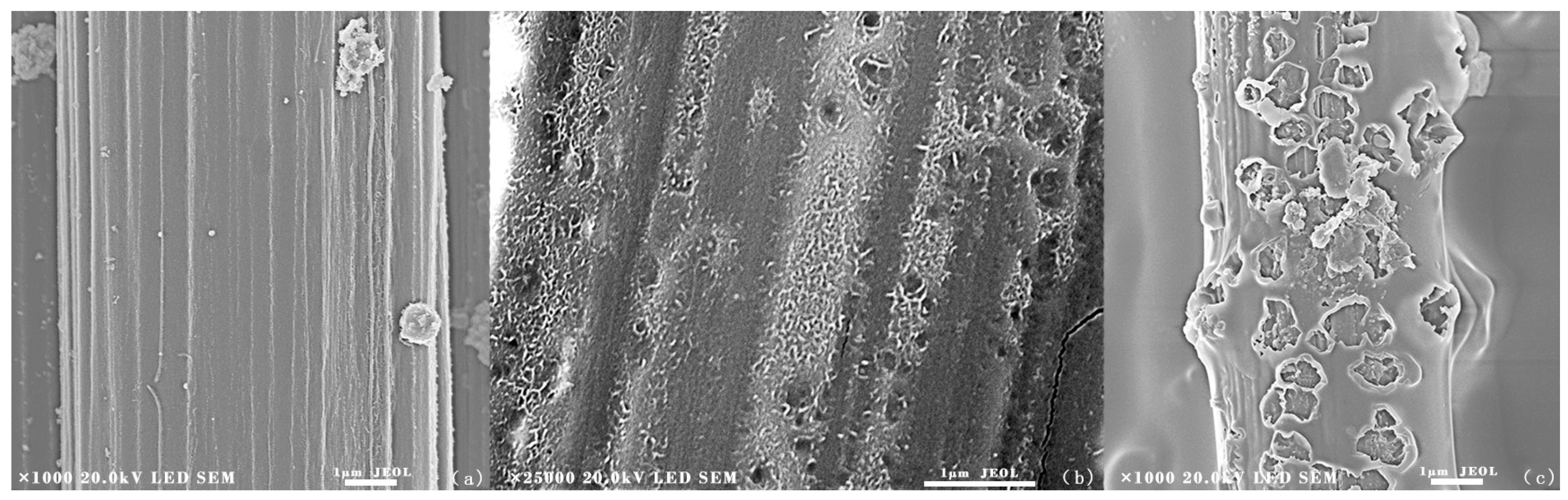
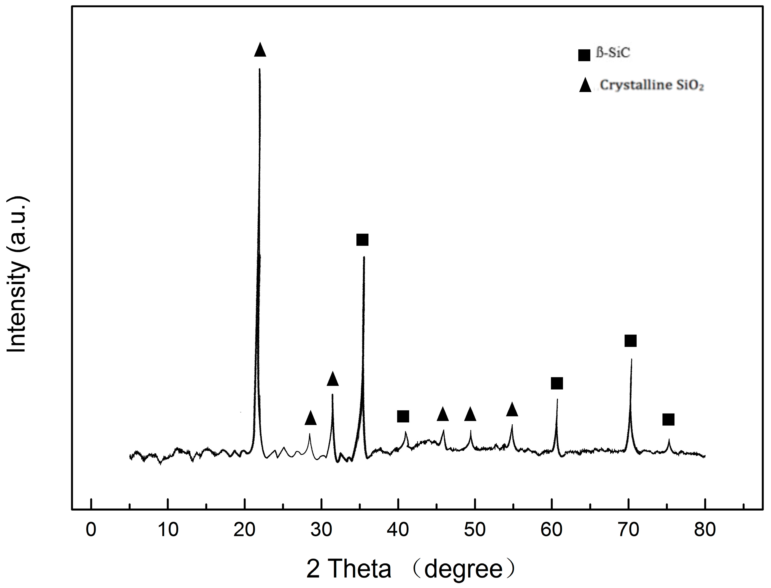
SiC/SiO2 coated CF were treated at 800 °C, 1000 °C and 1400 °C in the air environment for 15 min. Figure 5a shows the SEM image of the SiC/SiO2 coated CF heated at 800 °C for 15 min. The fibers stayed in the right shape and there were no cracks or pores at the surface, which means that the SiC/SiO2 coating had protected fibers well. From Figure 5b, the surface of 1000 °C treated SiO2 coated CF was more coarse and little cavities could be found due to the gas that had broken through the coating and some SiC nanoparticles had been peeled off from the coating. However, these cavities did not penetrate the coating, so the oxygen could not react with CF directly. The coated CF had acceptable mechanical property for such an environment, indicating that 1000 °C can be the proper temperature in the real application. Figure 5c presents the surface morphology of coated CF after 15 min 1400 °C treatment. It can be found that pores and cracks were distributed on the coating. The diameter of pores could be over 1 µm, which indicated that the coating had been seriously damaged. It can be deduced that the gas was formed inside the coating due to the edge of the pores was convex. By penetrating into the coating, oxygen could react with CF, leading the rapid oxidation of the fibers. Combine with XRD results (Figure 6). It can be concluded that although higher temperature had contributed to the formation of crystalline SiO2 at the surface of the coating, the inner oxidation still destroyed the anti-oxidation ability of the coating due to the gas formation.
Figure 7 is the TG analysis of CF with different coatings. The results show that SiC/SiO2 coating can effectively improve the anti-oxidation ability of CF in the air environment. Uncoated CF began to lose weight when the temperature was over 400 °C. The TG curve of uncoated CF started to decrease rapidly and decomposed completely around 850 °C. The SiC/SiO2 coated CF started to lose weight at 900 °C. Around 1400 °C, the residual weight of SiC/SiO2 coated CF was more than 57%. Moreover, the mass loss of coated CF was smaller, which means the oxidation rate of coated CF is slower than uncoated CF. When compared with the temperature of other silicide coatings that were fabricated with the traditional sol-gel method, the decomposition temperature of SiC/SiO2 coated CF had been improved significantly.
3.4. Oxidation Mechanism of Coated CF
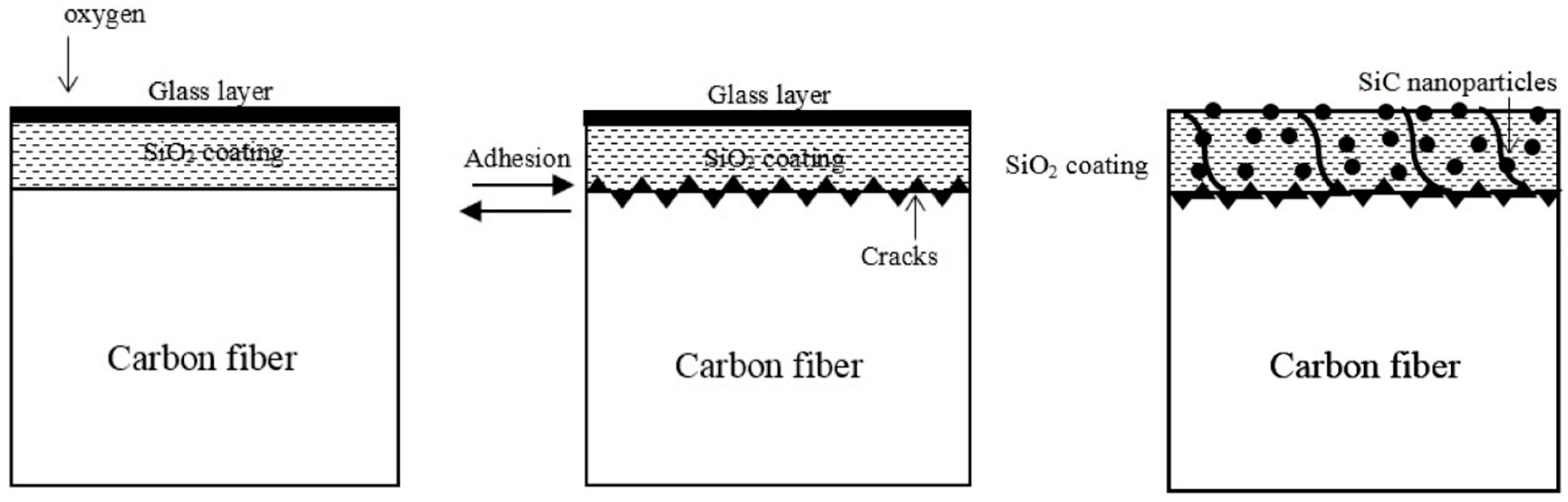
Figure 8 is the sketch of the cross-section of CF. It shows the oxidation mechanism of coated CF. From other report [34], the coating of thermal protection system should have a high melting point, low density, thermal shock resistance, and low thermal conductivity. Besides, the thickness of coating should be considered based on the purpose of the CF. To ensure the acceptable mechanical property of CF, the coating cannot be too thick.
When it comes to the samples that we prepared, both SiO2 and SiC had relative high melting points and SiC had similar coefficient of thermal expansion that makes them perfect to be used as thermal protection materials. From the mechanical test, it can be deduced that the thickness of SiC/SiO2 coating was appropriate. While the temperature increased, the silicon dioxide layer will be formed at the surface of the coating. The glass layer can protect the inner coating by preventing oxygen from penetration. When the temperature was lower than 1000 °C, the CF stayed in the right shape. Only small pores would be formed at the surface of the coating due to part of SiC nanoparticles reacting with oxygen to form CO2 and CO. However, once the temperature was over 1000 °C, the accumulated gases could lead cracks and pores in the coating. When oxygen contacted with CF, a large amount of gases destroyed the integrality of the coating. Besides, the coefficients of thermal expansion were different between the coating and CF substrate. With the temperature increased, thermally grown oxides could be formed at the interface of the coating and CF substrate, which leads to higher interface stress and a decrease in the strength of interfacial bonding. Some part of the coating might be peeled off from the CF. What’s more, all of the samples were put back to the room temperature as soon as the oxidation finished. The planar cracks could be formed by the thermal shock. Although SiC nanoparticles have great oxidation resistance potential, while the temperature is high enough, the activation energy of the particles can cause cracks along the interface. Once the oxygen came in the inner coating, SiC nanoparticles can form CO and CO2, which would damage the coating and accelerate the oxidation speed of CF.
4. Conclusions
This study proposed a modified sol-gel method to fabricate SiC/SiO2 coating at the surface of CF. The coating can improve the oxidation resistance ability of CF at high temperature environment. The best TEOS/water ratio to make SiO2 sol had been determined. Attributed to the SiC/SiO2 coating, the anti-oxidation performance of CF had been increased. The residual weight of coated CF was more than 57% when the temperature was 1400 °C. The mechanical property of SiC/SiO2 coated CF only had little differences between uncoated CF when the temperature was lower than 1000 °C. In the future, to reach better anti-oxidation ability of coated CF, a new method should be developed to increase the interface strength between coating and the CF and lower the formation temperature of coating.
Author Contributions
In this paper, Zhixiong Huang provided the direction of research. Guangyuan Yang designed the experiment and wrote the manuscript. Bo Wang helped to do the heat-treatment experiment and analyzed the XRD part. Xu Wang assisted with preparing the samples.
Conflicts of Interest
The authors declare no conflict of interest.
References
- Yuan, Y.; Sun, Y.; Yan, S.; Zhao, J.; Liu, S.; Zhang, M.; Zheng, X.; Jia, L. Multiply fully recyclable carbon fibre reinforced heat-resistant covalent thermosetting advanced composites. Nat. Commun. 2017, 8, 14657. [Google Scholar] [CrossRef] [PubMed]
- Toldy, A.; Niedermann, P.; Pomázi, Á.; Marosi, G.; Szolnoki, B. Flame Retardancy of Carbon Fibre Reinforced Sorbitol Based Bioepoxy Composites with Phosphorus-Containing Additives. Materials 2017, 10, 467. [Google Scholar] [CrossRef] [PubMed]
- Wang, J.; Zhang, X.; Miao, Y.; Li, Y.; Xi, X.; Zhong, X.; Pei, X.; He, L.; Huang, Q. The influences of carbon nanotubes introduced in three different phases of carbon fiber/pyrolytic carbon/silicon carbide composites on microstructure and properties of their composites. Carbon 2018, 129, 409–414. [Google Scholar] [CrossRef]
- Fahrenholtz, W.G.; Hilmas, G.E. Ultra-High Temperature Ceramics: Materials for Extreme Environment Applications. Scr. Mater. 2017, 129, 94–99. [Google Scholar] [CrossRef]
- Yu, S.; Park, K.; Lee, J.W.; Hong, S.M.; Park, C.; Han, T.H.; Koo, C.M. Enhanced thermal conductivity of epoxy/Cu-plated carbon fiber fabric composites. Macromol. Res. 2017, 25, 559–564. [Google Scholar] [CrossRef]
- Zhuang, Q.; Zhang, P.; Li, M.; Yan, H.; Yu, Z.; Lu, Q. Microstructure, Wear Resistance and Oxidation Behavior of Ni-Ti-Si Coatings Fabricated on Ti6Al4V by Laser Cladding. Materials 2017, 10, 1248. [Google Scholar] [CrossRef] [PubMed]
- Zamani, P.; Valefi, Z. Microstructure, phase composition and mechanical properties of plasma sprayed Al2O3, Cr2O3 and Cr2O3-Al2O3 composite coatings. Surf. Coat. Technol. 2017, 316, 138–145. [Google Scholar] [CrossRef]
- Du, B.; Hong, C.; Qu, Q.; Zhou, S.; Liu, C.; Zhang, X. Oxidative protection of a carbon-bonded carbon fiber composite with double-layer coating of MoSi2-SiC whisker and TaSi2-MoSi2-SiC whisker by slurry method. Ceram. Int. 2017, 43, 9531–9537. [Google Scholar] [CrossRef]
- Xiaojun, M.; Zhou, W.; Yin, C. Structure and Photocatalytic Properties of Mn-Doped TiO2 Loaded on Wood-Based Activated Carbon Fiber Composites. Materials 2017, 10, 631. [Google Scholar] [CrossRef] [PubMed]
- Farrokhzad, M.A. High temperature oxidation behaviour of autocatalytic Ni-P-BN (h) coatings. Surf. Coat. Technol. 2017, 309, 390–400. [Google Scholar] [CrossRef]
- Jia, Y.; Li, H.; Feng, L.; Sun, J.; Li, K.; Fu, Q. Ablation behavior of rare earth La-modified ZrC coating for SiC-coated carbon/carbon composites under an oxyacetylene torch. Corros. Sci. 2016, 104, 61–70. [Google Scholar] [CrossRef]
- Huo, C.; Guo, L.; Feng, L.; Wang, C.; Li, Z.; Zhang, Y.; Kou, G. Improving the oxidation resistance under thermal shock condition of SiC-coated C/C composites with refined SiC grain size using ferrocene. Surf. Coat. Technol. 2017, 316, 39–47. [Google Scholar] [CrossRef]
- Doganli, G.; Yuzer, B.; Aydin, I.; Gultekin, T.; Con, A.H.; Selcuk, H.; Palamutcu, S. Functionalization of cotton fabric with nanosized TiO2 coating for self-cleaning and antibacterial property enhancement. J. Coat. Technol. Res. 2016, 13, 257–265. [Google Scholar] [CrossRef]
- Yong, X.; Cao, L.; Huang, J.; Kong, W.; Su, J.; Li, C.; Ouyang, H.; Zhou, L.; Liu, J. Microstructure and oxidation protection of a MoSi2/SiO2-B2O3-Al2O3, coating for SiC-coated carbon/carbon composites. Surf. Coat. Technol. 2017, 311, 63–69. [Google Scholar] [CrossRef]
- Zhang, Y.P.; Shen, Y.H.; Chen, W.W.; Cheng, H.W.; Wang, L. Preparation of Continuous Al2O3/Y2O3 Coating on Carbon Fiber by a Novel Aqueous Plasma Electrolysis. Mater. Sci. Forum Trans. Tech. Publ. 2017, 898, 1575–1582. [Google Scholar] [CrossRef]
- Li, L. Damage evolution and life prediction of cross-ply C/SiC ceramic-matrix composite under cyclic fatigue loading at room temperature and 800 °C in air. Materials 2015, 8, 8539–8560. [Google Scholar] [CrossRef] [PubMed]
- Huang, X.; Sun, S.; Tu, G.; Lu, S.; Li, K.; Zhu, X. The Microstructure of Nanocrystalline TiB2 Films Prepared by Chemical Vapor Deposition. Materials 2017, 10, 1425. [Google Scholar] [CrossRef] [PubMed]
- Szczurek, A.; Barcikowski, M.; Leluk, K.; Babiarczuk, B.; Kaleta, J.; Krzak, J. Improvement of Interaction in a Composite Structure by Using a Sol-Gel Functional Coating on Carbon Fibers. Materials 2017, 10, 990. [Google Scholar] [CrossRef] [PubMed]
- Tatarko, P.; Casalegno, V.; Hu, C.; Salvo, M.; Ferraris, M.; Reece, M.J. Joining of CVD-SiC coated and uncoated fibre reinforced ceramic matrix composites with pre-sintered Ti3SiC2 MAX phase using Spark Plasma Sintering. J. Eur. Ceram. Soc. 2016, 36, 3957–3967. [Google Scholar] [CrossRef]
- Januś, M.; Kyzioł, K.; Kluska, S.; Konefał-Góral, J.; Małek, A.; Jonas, S. Plasma Assisted Chemical Vapour Deposition—Technological Design of Functional Coatings. Arch. Metall. Mater. 2015, 60, 909–914. [Google Scholar] [CrossRef]
- Jonas, S.; Januś, M.; Jaglarz, J.; Kyzioł, K. Formation of SixNy (H) and C:N:H layers by Plasma-Assisted Chemical Vapor Deposition method. Thin Solid Films 2016, 600, 162–168. [Google Scholar] [CrossRef]
- Lee, E.S.; Lee, C.H.; Chun, Y.S.; Han, C.J.; Lim, D.S. Effect of hydrogen plasma-mediated surface modification of carbon fibers on the mechanical properties of carbon-fiber-reinforced polyetherimide composites. Compos. Part B Eng. 2017, 116, 451–458. [Google Scholar] [CrossRef]
- Guo, Z.; Sang, L.; Wang, Z.; Chen, Q.; Yang, L.; Liu, Z. Deposition of copper thin films by plasma enhanced pulsed chemical vapor deposition for metallization of carbon fiber reinforced plastics. Surf. Coat. Technol. 2016, 307, 1059–1064. [Google Scholar] [CrossRef]
- Kern, F.; Gadow, R. Liquid phase coating process for protective ceramic layers on carbon fibers. Surf. Coat. Technol. 2002, 151–152, 418–423. [Google Scholar] [CrossRef]
- Zhou, Q.; Peng, Z.; Yang, M.; Hu, H.; Song, N.; Ni, L. A linear polycarbosilane containing m-carborane units: Synthesis and characterization as precursor for SiC/B4C ceramics. High Perform. Polym. 2017, 0954008317746730. [Google Scholar] [CrossRef]
- Wang, J.; Lin, W.; Yan, X.; Wu, X.; Wu, F.; Yang, Y. Preparation and microstructure of Al2O3–SiO2–TiO2 coating on three-dimensional braided carbon fiber by sol–gel technology. Mater. Des. 2016, 89, 928–932. [Google Scholar] [CrossRef]
- Figueira, R.B.; Callone, E.; Silva, C.J.; Pereira, E.V.; Dirè, S. Hybrid coatings enriched with tetraethoxysilane for corrosion mitigation of hot-dip galvanized steel in chloride contaminated simulated concrete pore solutions. Materials 2017, 10, 306. [Google Scholar] [CrossRef] [PubMed]
- Xiang, Y.; Li, X.; Du, A.; Wu, S.; Shen, J.; Zhou, B. Timing of polyethylene glycol addition for the control of SiO2 sol structure and sol–gel coating properties. J. Coat. Technol. Res. 2017, 14, 447–454. [Google Scholar] [CrossRef]
- Xia, K.; Lu, C.; Yang, Y. Preparation of anti-oxidative SiC/SiO2 coating on carbon fibers from vinyltriethoxysilane by sol–gel method. Appl. Surf. Sci. 2013, 265, 603–609. [Google Scholar] [CrossRef]
- Liu, H.; Liu, F.J.; Wang, H.J.; Wang, H.F.; Cheng, L.; Fan, L.D. Sample Preparation Method for Mechanical Property Test of Carbon Fiber. CN 101949791 A, 16 September 2010. [Google Scholar]
- Rubber and Plastics Test Equipment—Tensile, Flexural and Compression Types (Constant Rate of Traverse)—Specification; International Organization for Standardization: Geneva, Switzerland, 2002; ISO 5893:2002.
- Vautard, F.; Fioux, P.; Vidal, L.; Dentzer, J.; Schultz, J.; Nardin, M.; Defoort, B. Influence of an oxidation of the carbon fiber surface by boiling nitric acid on the adhesion strength in carbon fiber-acrylate composites cured by electron beam. Surf. Interface Anal. 2013, 45, 722–741. [Google Scholar] [CrossRef]
- Gao, S.L.; Mäder, E.; Plonka, R. Nanocomposite coatings for healing surface defects of glass fibers and improving interfacial adhesion. Compos. Sci. Technol. 2008, 68, 2892–2901. [Google Scholar] [CrossRef]
- Jiménez, C.; Mergia, K.; Lagos, M.; Yialouris, P.; Agote, I.; Liedtke, V.; Messoloras, S.; Panayiotatos, Y.; Padovano, E.; Badini, C.; et al. Joining of ceramic matrix composites to high temperature ceramics for thermal protection systems. J. Eur. Ceram. Soc. 2016, 36, 443–449. [Google Scholar] [CrossRef]
Figure 1.
X-ray diffraction (XRD) analysis of silicon dioxide (SiO2) coating with different Water/TEOS ratio (a) 1/3; (b) 1/1; (c) 1/5; (d) 1/7.
Figure 1.
X-ray diffraction (XRD) analysis of silicon dioxide (SiO2) coating with different Water/TEOS ratio (a) 1/3; (b) 1/1; (c) 1/5; (d) 1/7.

Figure 2.
Scanning Electron Microscope (SEM) images of (a) uncoated carbon fibers (CF); (b) SiO2 coated CF; (c) SiC/SiO2 coated CF; and, (d) cross-section of coated CF.
Figure 2.
Scanning Electron Microscope (SEM) images of (a) uncoated carbon fibers (CF); (b) SiO2 coated CF; (c) SiC/SiO2 coated CF; and, (d) cross-section of coated CF.

Figure 3.
EDS analysis of SiC/SiO2 coated CF. Scale bar represents 10 µm.

Figure 4.
XRD images of SiC/SiO2 coated CF.

Figure 5.
SEM micrograph of the surface of (a) SiC/SiO2 coated CF(800 °C,15 min); (b) SiC/SiO2 coated CF(1000 °C,15 min); and, (c) SiC/SiO2 coated CF(1400 °C,15 min).
Figure 5.
SEM micrograph of the surface of (a) SiC/SiO2 coated CF(800 °C,15 min); (b) SiC/SiO2 coated CF(1000 °C,15 min); and, (c) SiC/SiO2 coated CF(1400 °C,15 min).

Figure 6.
XRD analysis of SiC/SiO2 coated CF with 1400 °C treated for 15 min.

Figure 7.
Thermal Gravimetric (TG) curves of uncoated CF and SiC/SiO2 coated CF.
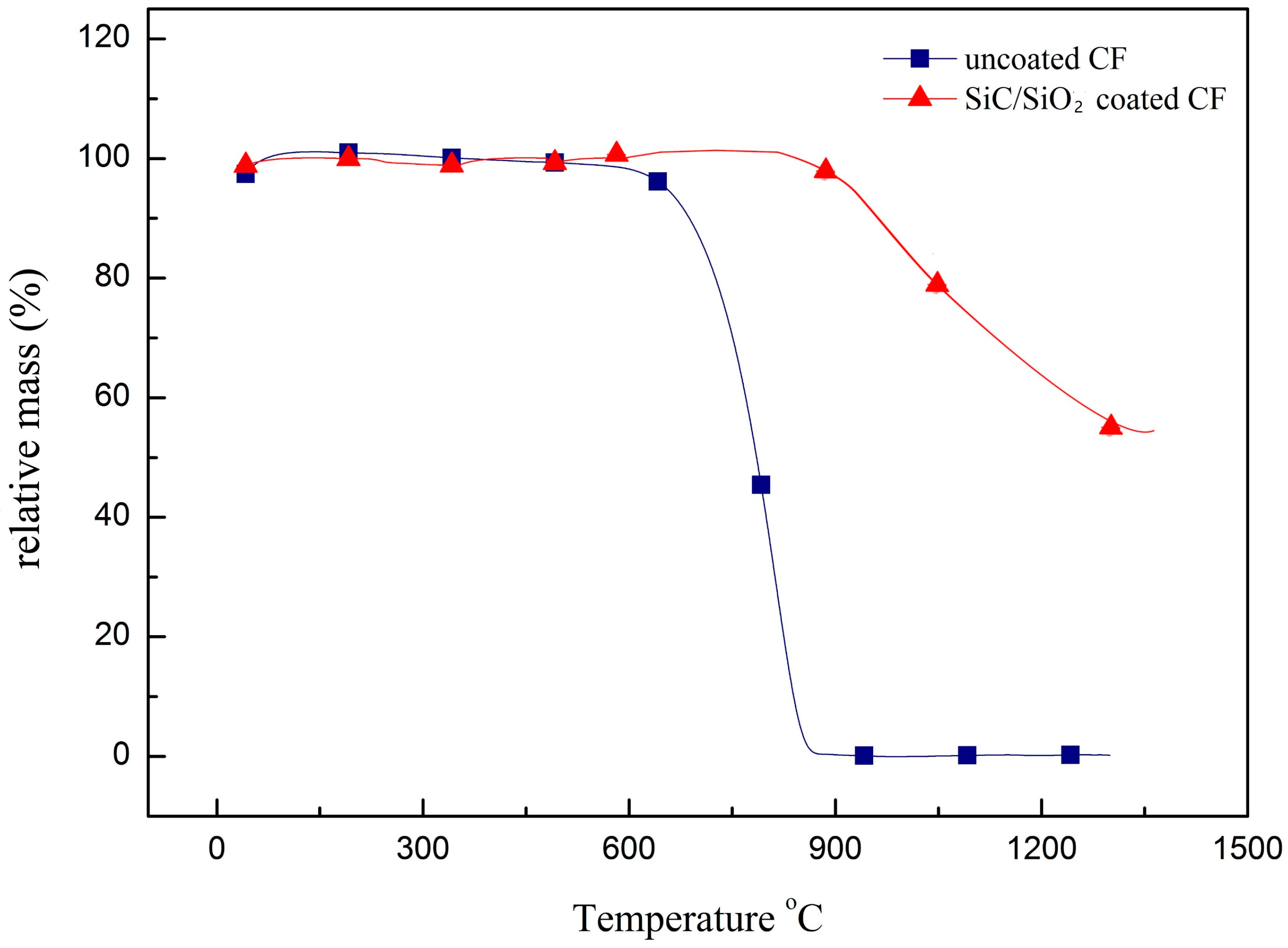
Figure 8.
Oxidation mechanism of coated CF.


Table 1.
Result of samples with different water/TEOS ratio.
| Sample Number | Water/TEOS | SiO2 Coating |
|---|---|---|
| Sample 1 | 1/1 | The thickest coating with no cracks. The surface is not uniform. |
| Sample 2 | 1/3 | Thinner than Sample 1, and the surface is uniform. |
| Sample 3 | 1/5 | The surface is not uniform, and cracks appear. |
| Sample 4 | 1/7 | It cannot form SiO2 coating. |
Table 2.
Mechanical property of different CF.
| Sample | Strength MPa | Young’s Modulus GPa | Fracture Elongation % | Standard Deviation of Modulus |
|---|---|---|---|---|
| Uncoated CF | 2745 | 223 | 1.75 | 5.98 |
| SiO2 coated CF | 2980 | 207 | 1.40 | 4.24 |
| SiC/SiO2 coated CF | 3098 | 210 | 1.43 | 5.12 |
| 800 °C treated SiO2 coated CF | 2455 | 132 | 1.22 | 3.35 |
| 1000 °C treated SiO2 coated CF | 1832 | 101 | 1.16 | 4.31 |
| 1400 °C treated SiO2 coated CF | 1102 | 67 | 0.65 | 4.89 |
© 2018 by the authors. Licensee MDPI, Basel, Switzerland. This article is an open access article distributed under the terms and conditions of the Creative Commons Attribution (CC BY) license (http://creativecommons.org/licenses/by/4.0/).
Share and Cite
MDPI and ACS Style
Yang, G.; Huang, Z.; Wang, X.; Wang, B. Fabrication and Anti-Oxidation Ability of SiC-SiO2 Coated Carbon Fibers Using Sol-Gel Method. Materials 2018, 11, 350. https://doi.org/10.3390/ma11030350
AMA Style
Yang G, Huang Z, Wang X, Wang B. Fabrication and Anti-Oxidation Ability of SiC-SiO2 Coated Carbon Fibers Using Sol-Gel Method. Materials. 2018; 11(3):350. https://doi.org/10.3390/ma11030350
Chicago/Turabian StyleYang, Guangyuan, Zhixiong Huang, Xu Wang, and Bo Wang. 2018. "Fabrication and Anti-Oxidation Ability of SiC-SiO2 Coated Carbon Fibers Using Sol-Gel Method" Materials 11, no. 3: 350. https://doi.org/10.3390/ma11030350
Note that from the first issue of 2016, this journal uses article numbers instead of page numbers. See further details here.