The Formation Mechanism and Corrosion Resistance of a Composite Phosphate Conversion Film on AM60 Alloy


1
Key Laboratory of Fluid and Power Machinery of Ministry of Education, School of Materials Science and Engineering, Xihua University, Chengdu 610039, China
2
Clean Energy Materials and Engineering Center, School of Electronic Science and Engineering, State Key Laboratory of Electronic Thin Film and Integrated Devices, University of Electronic Science and Technology of China, Chengdu 611731, China
*
Author to whom correspondence should be addressed.
Materials 2018, 11(3), 402; https://doi.org/10.3390/ma11030402
Submission received: 22 January 2018
/
Revised: 6 March 2018
/
Accepted: 6 March 2018
/
Published: 8 March 2018
(This article belongs to the Section Thin Films and Interfaces)
Abstract
:Magnesium alloy AM60 has high duc and toughness, which is expected to increase in demand for automotive applications. However, it is too active, and coatings have been extensively studied to prevent corrosion. In this work, a Ba-containing composite phosphate film has been prepared on the surface of AM60. The composition and formation mechanism of the film have been investigated using a scanning electronic microscope equipped with energy dispersive X-ray spectroscopy, Fourier transform infrared, X-ray photoelectron spectroscopy, and X-ray diffractometry tests. The corrosion resistance of the film has been measured by electrochemical and immersion tests. The results show that the deposition film has fully covered the substrate but there are some micro-cracks. The structure of the film is complex, and consists of MgHPO4·3H2O, MnHPO4·2.25H2O, BaHPO4·3H2O, BaMg2(PO4)2, Mg3(PO4)2·22H2O, Ca3(PO4)2·xH2O, and some amorphous phases. The composite phosphate film has better anticorrosion performance than the AM60 and can protect the bare alloy from corrosion for more than 12 h in 0.6 M NaCl.
1. Introduction
With excellent properties, such as low density, mechanical stability, and high damping capacity, magnesium (Mg) alloys are attracting much recent attention. However, Mg alloys have not been widely used yet due to the poor corrosion resistance, which is the main undesirable property [1]. Surface treatment is a general way to control corrosion by forming a barrier layer to isolate the bare alloys from the environment [2]. Phosphate conversion coatings (PCCs) are promising coatings because most metal phosphates are insoluble in water and have high chemical stability [3]. The utilization of PCCs has a history of centuries, and this traditional mature technology has been successfully exploited to protect steel, zinc, and aluminum [4,5,6].
PCCs on Mg alloys have been investigated widely [7,8,9,10,11,12,13,14,15,16,17,18,19]. Phosphating has always been carried out in the acidic solution containing Mn2+, Zn2+, Ca2+, Na+, and Mg2+ [13]. For example, Phuong et al. synthesized a Zn PCC on AZ91, which consisted of an outer crystal Zn3(PO4)2·4H2O layer and inner MgZn2(PO4)2 and Mg3(PO4)2 layer. The longest corrosion initiation time of the coated sample was about 12 h in 0.5 M NaCl solution [7]. Song et al. has improved the generally porous structure of the Ca PCCs through an environmentally friendly solution containing Ca(NO3)2 and NH4H2PO4 with ultrasonic agitation. However, the dissolution of the flake particles into small chipping occurred after being immersed in the simulated body fluid for 2 h [9]. Zhou et al. prepared a Mn PCC, the corrosion potential (Ecorr) and the radius of the capacity impedance of which increased distinctly in 3.5 wt % NaCl solution compared with that of the AZ91 substrate, displaying excellent anticorrosion performance [8]. Chen et al. [12] pointed out that Mn PCC had desirable corrosion resistance, which was more stable and corrosion resistant than its Zn and Ca peers. Recently, Ba PCC has been developed for the corrosion protection of Mg alloys [14,15,16], which also shows great anticorrosion properties. For instance, it was reported that the coating prepared in a simple solution with Ba(NO3)2 and NH4H2PO4 could effectively decrease the corrosion current density (icorr) of the AZ31 alloy from 154 to 3.78 μA·cm−2 in 5 wt % NaCl solution [15]. In addition, the combination of different phosphates has a tendency to strengthen the corrosion resistance of the coatings. Wang et al. synthesized a Zn–Mn PCC, which was composed of Zn, Zn3(PO4)2, MnHPO4, and Mn3(PO4)2. The corrosion properties of Mg–Li alloy were improved greatly by this composite coating [11]. Hence, in the present work, we choose Mn2+ and Ba2+ as the main ingredients in order to obtain an anticorrosive coating. However, the Ba PCC prepared by Chen [15] featured a two-layer structure, and the top layer consisted of large crystals exhibiting a lower adhesion than the under layer. Therefore, further studies are necessary to improve the present process. Zhou et al. pointed out that adding a Ca2+ compound in the bath could improve the combination between the substrate and coating [18]. In order to achieve both high corrosion resistance and strong adhesion, a small amount of Ca(NO3)2 is also added in this work.
Moreover, it is notable that the composition of the PCCs prepared in solutions containing various anions is always complicated. In the previous work, Liu et al. prepared a Ba PCC on AZ91D Mg alloy with Ba(NO3)2, Mn(NO3)2, and NH4H2PO4 as precursors [16]. However, the component of the coating was only tested using the energy dispersive X-ray spectroscopy (EDS), and the real composition of the coating was unclear. It is also remarkable that the phosphating mechanism may vary in different phosphating systems. As a result, this work aims at clearly illustrating the structure and formation mechanism of the coating prepared using the present process. The corrosion performance of the coating is also studied.
2. Experimental
2.1. Fabrication of the Film
The material used in this study was die-cast AM60 alloy (5.94 wt % Al, 0.43 wt % Mn, 0.11 wt % Zn, 0.03 wt % Si, 0.004 wt % Cu, 0.001 wt % Fe, and bal. Mg). The samples were ground with 2000 grit SiC paper, ultrasonically cleaned in ethyl alcohol, and then dried in the cold air. According to our preliminary experiment exploration, the optimum formation process has been chosen to synthesize the film, which is as follows. 10 mL·L−1 Mn(NO3)2, 10 g·L−1 Ba(NO3)2, 6 g·L−1 Ca(NO3)2·4H2O, and 20 g·L−1 NH4H2PO4 were selected as the ingredients of the treating solution. The pH value of the solution was settled to 3, the treating temperature was room temperature (RT) (30 ± 2 °C), and the treating time was 0.5 h. Then, in order to compare the adhesion of the film formed by the above process with an appropriate concentration of the Ba2+ ingredient, another film was prepared at 60 °C in the solution containing of 10 mL·L−1 Mn(NO3)2, 15 g·L−1 Ba(NO3)2, and 20 g·L−1 NH4H2PO4, which was named as the film for comparison.
2.2. Characterization
The morphology of the film was observed using a Quanta 250 FEG environmental scanning electronic microscope (ESEM, FEI, Hillsboro, OR, USA). The composition was analyzed by EDS, Fourier transform infrared (FTIR), X-ray photoelectron spectroscopy (XPS) and X-ray diffraction (XRD). The FTIR spectrum was obtained on a Tensor 27 spectrometer (Bruker, Karlsruhe, Germany) in the wavenumber range of 400–4000 cm−1. The XPS was probed using an ESCALAB 250 XPS (Thermo Fisher Scientific, Waltham, MA, USA) with Al Kα radiation. The power was 150 W, the pass energy was 50.0 eV, and the step size was 0.1 eV. The energy values were referenced to the adventitious C1s peak at 284.6 eV. XRD was carried out on a PW1700 diffractometer (Philips, Amsterdam, The Netherlands) with a Cu target (λ = 0.154 nm). The film was scraped from the samples and prepared as the finely pressed powderfor the XRD test. Electrochemical tests were performed using a ParStat 4000 potentiostat (Ametec, Berwyn, PA, USA) with a three-electrode cell system, which consists of a saturated calomel electrode (SCE) reference electrode, a platinum counter electrode, and a working electrode with an exposed area of 1 cm2. The samples were immersed in the aggressive medium for 300 s before the experiment. The polarization curves were obtained at a constant voltage scan rate of 0.5 mV·s−1. Electrochemical impedance spectroscopy (EIS) was conducted with the frequency swept from 100 kHz to 10 mHz, with a perturbation amplitude of 5 mV. An immersion test was carried out according to GB 10124-88 of China. The corrosion testing solution was 0.6 M NaCl solution at RT.
3. Results and Discussion
3.1. SEM Morphology and Adhesion of the Films
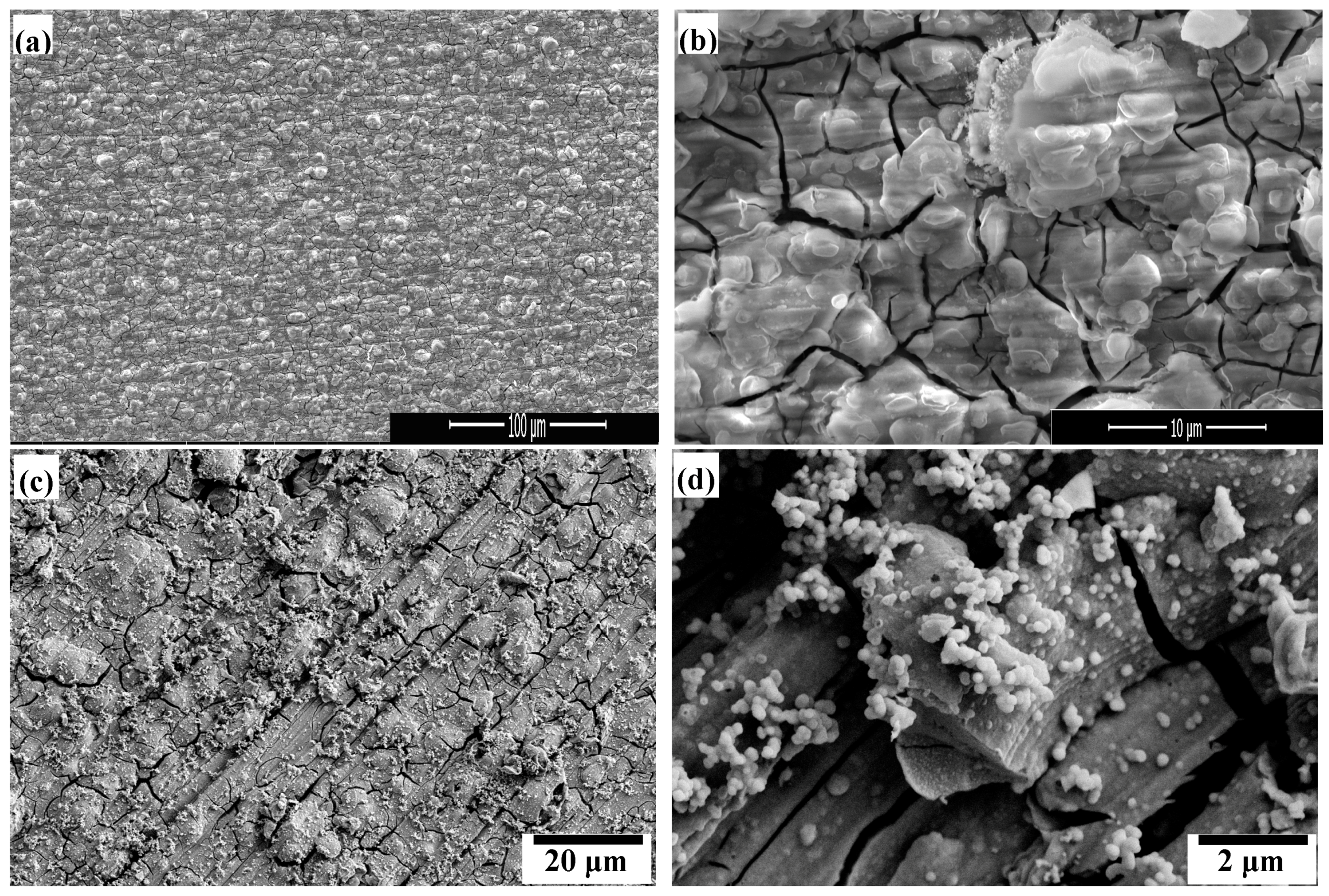
The SEM morphology of the films is shown in Figure 1. The deposition film prepared by the optimum formation process has fully covered the substrate, but micro-cracks can also be observed. The surface of the film is not very smooth and has tubercles. Many island particles can be recognized from the high-resolution image. Cracks are frequently observed in PCCs on Mg alloys. These cracks might arise from the severe H2 evolution during the synthesis process and the dehydration. During the drying process, the coexistence of voids caused by H2O evaporation and residual stress in the coating led to the coating shrinkage and crack formation [15,20,21,22,23,24]. As a protective coating, such a surface cannot provide long-term protection because of the cracked microstructure [23]. However, the cracking of the surface is hard to avoid, thus the protective effect of the PCCs may be limited. In Figure 1c,d, the surface of the film for comparison formed in the solution with high Ba2+ concentration and no Ca2+ ingredient was not very “clean”, which was much rougher compared to the film in Figure 1a. From the high-resolution image, it is observed that the film is heterogeneous with a combination of nanosphere particles. These particles may be easily detached, resulting in the poor adhesion of the film. As a consequence, the film prepared by the optimum formation process exhibits better adhesion than the film for comparison, according to a simple tape test (i.e., the adhesion of the tape is worse after it is pulled off from the film for comparison).
3.2. Composition Analysis of the Film
The chemical composition of the film was analyzed using EDS, FTIR, XPS, and XRD. The content of various elements of the film detected by EDS is displayed in Table 1. It discloses that the composition of the film is very complex, including C, O, P, Mg, Ca, Mn, and Ba. The content of Ca is much less than that of the other metal elements. It should be mentioned that the signal of Al may be mainly attributed to the matrix, because Al has not been tested by the XPS analysis.
The FTIR spectrum of the film is shown in Figure 2. Physically adsorbed water molecules can be identified by the broad band around 3100–3500 cm−1 [25,26]. The band at 2380 cm−1 may correspond to the vibration of OH−, and the strong peak around 1658 cm−1 may be ascribed to HPO42− or crystal water in the film [19,27]. In addition, many peaks are observed in the range of 830–1140 cm−1, which may be assigned to the vibration band of PO43− or HPO42− [19,27,28,29,30]. Furthermore, it can be seen that the peak for HPO42− is much sharper, indicating that the content of the HPO42− anions is much higher than PO43−. The bands in the range of 400–800 cm−1 are attributed to metal–oxygen stretching [31,32]. Because there are too many kinds of metal ions, the peaks in this range are very complex.
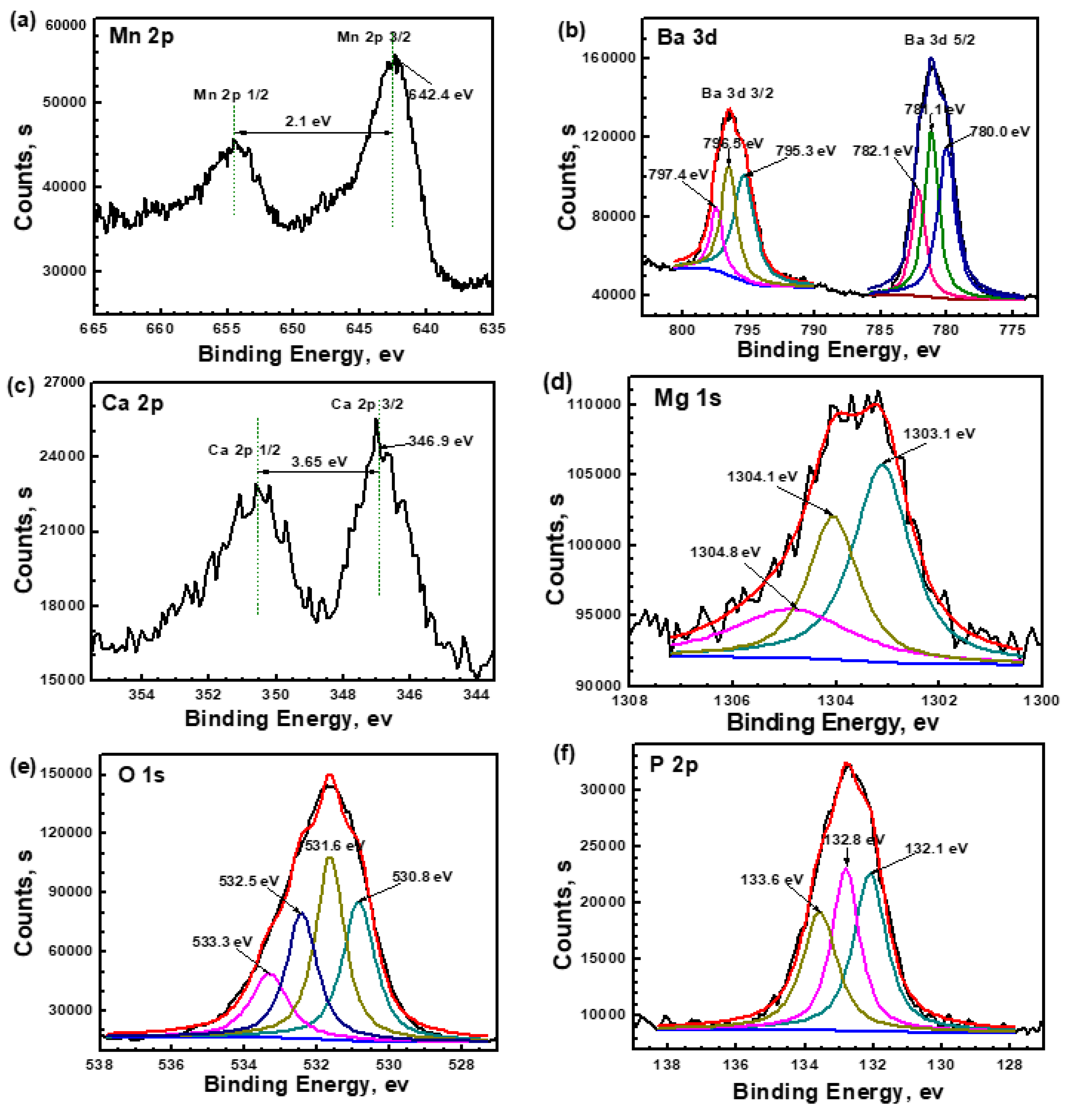
Figure 3 shows the XPS analysis of the film after 30 s of etching. The high-resolution spectra of Mn 2p, Ba 3d, and Ca 2p all show two distinctive peaks as a result of spin orbit splitting, which is the energy peak at lower energy and is the satellite peak at high energy. The peak corresponding to Mn 2p3/2 is located at 642.4 eV in Figure 4a. The binding energy (BE) distance between the energy peak and satellite peak is 2.1 eV. The Mn 2p3/2 peak shifts toward the higher BE compared to that of Mn3(PO4)2 in the reference of [12]. Hence, the composition of Mn2+ may be assigned to MnHPO4. Figure 4b shows two distinctive peaks, Ba 3d5/2 and Ba 3d3/2, which are both divided into three separate peaks. The width of three pairs of Ba 3d peaks is about 15.3 eV, which can be attributed to Ba2+ [15,33]. The peak of Ba 3d5/2 at 780.0 eV can be attributed to BaHPO4 [15]. The BE of the peak at 782.1 eV is a little larger than that of Ba3(PO4)2 in the reference [15], indicating that this component is not a simple Ba3(PO4)2, and the Ba–PO4 bond may be bonded with other elements to form a more complicated component. There is an intensive peak at 781.1 eV, indicating another Ba2+ compound. However, there is no material related to this BE in the existing database. The high-resolution spectrum of Ca 2p splits into two peaks, Ca 2p3/2 and Ca 2p1/2, with a separation of about 3.65 eV. The peak of Ca 2p3/2 at 346.9 eV can be attributed to tricalcium phosphate Ca3(PO4)2 [34]. The Mg 1s spectrum is broad, which can be resolved into three components. BE at 1303.1 eV is attributed to MgHPO4 [24,35]. The peak at 1304.1 eV is assigned to Mg3(PO4)2 [19]. There is a small shoulder peak at the high BE 1304.8 eV, indicating another Mg2+ compound, but the exact component is difficult to identify due to the absence of more reliable data. Figure 4e presents the high resolution spectrum of O 1s, which is deconvoluted into four peaks. The peak at 533.3 eV can be attributed to P–OH [24,35]. The BE at 532.5 eV is H2O, but it should be in the form of crystallization water [36]. The peak at 531.6 eV is attributed to P=O, while the peak at 530.8 eV may be attributed to P=O or OH− [15,24,35]. The spectrum of P 2p is divided into three peaks, 132.1, 132.8, and 133.6 eV. The peak at low BE is assigned to PO43−, while the other two higher BE peaks are attributed to HPO42− [12,19,24,37,38]. It can be implied that hydrogen phosphates are the main components and phosphates are the minor components. This result is in accordance with the FTIR detection that the content of HPO42− is much more than that of PO43−.
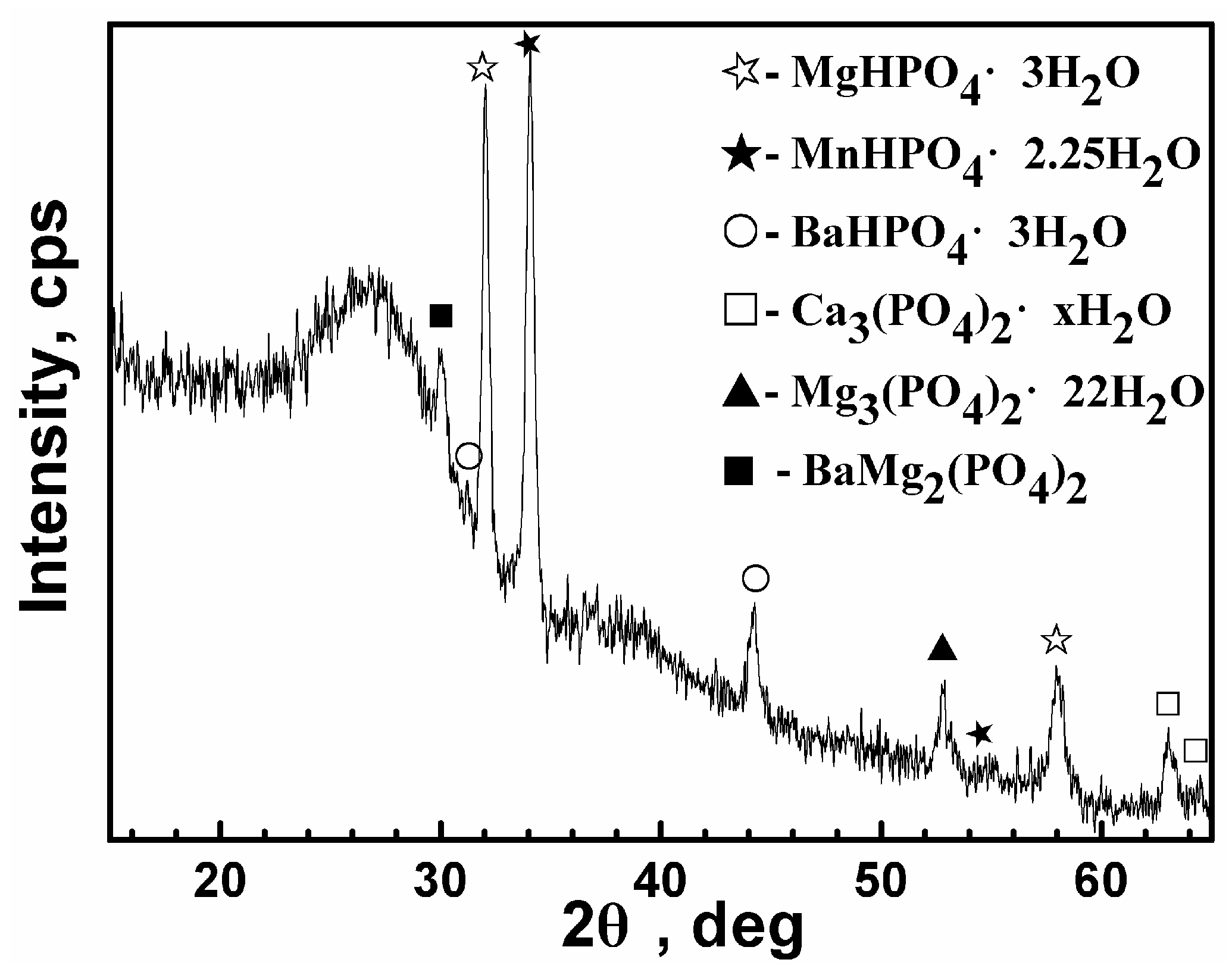
To further confirm the structure of the film, XRD measurement was also carried out as shown in Figure 4. The major phases in the film are hydrophosphates MgHPO4·3H2O, MnHPO4·2.25H2O, and BaHPO4·3H2O, as well as a minority of three other phosphates, including BaMg2(PO4)2, Mg3(PO4)2·22H2O, and Ca3(PO4)2·xH2O. It is in accordance with the FTIR and XPS analysis that the main anion in the film is HPO42−. The content of Ca3(PO4)2·xH2O is small, which is in accordance with the EDS analysis that the content of Ca is much less than that of the other metal elements. The phases in the film tested by XRD are coincident with the XPS analysis. It is noticed that there is an unknown peak in the XPS spectrum of both Ba 3d and Mg 1s, which may correspond to this complicated component, BaMg2(PO4)2. In addition, a broad diffuse diffraction pattern located at 2θ = 23°–29° is observed, indicating that the film is composed of some amorphous phases. Regarding the phenomenon where there was a small content of BaHPO4·3H2O and BaMg2(PO4)2 tested by XRD but there was a great amount of Ba element detected by EDS, it suggests that the amorphous phases may be mainly Ba-containing compounds. The XRD pattern in other works has also confirmed the lack of crystallinity in the Ba phosphate cement [14]. Hence, it can be implied that the intensive Ba 3d5/2 peak at 781.1 eV may be assigned to the amorphous compound. In other words, XRD shows both the amorphous and crystalline nature of this composite PCC, and the crystalline phases are hydrophosphates or phosphate compounds.
On the basis of the above composition analysis, an analysis of the formation mechanism of this composite phosphate film has been proposed. The possible reactions are listed as follows.
Firstly, once the substrate is exposed to the phosphate electrolyte solution, Mg is dissolved to produce Mg2+, resulting in a large increase in the OH− concentration and hydrogen evolution.
Mg → Mg2+ + 2e
2H2O + 2e →H2 ↑ + 2OH−
In addition, the dissolution reaction is much faster in the acidic bath, resulting in the generation of more hydrogen and promoting the OH− concentration at the interface of the metal and the solution.
Subsequently, the OH− reacts with H2PO4− to form HPO42−. As we know, H2PO4− is easily reduced to HPO42−, but HPO42− is difficult to reduce to PO43− because of the strong bond energy of H+ and PO43− [9]. In addition, the H2 evolution can resist further movement of HPO42− in the solution to the substrate surface [35]. As a result, only minor amounts of HPO42− in the solution adjacent to the metal surface continues to react with OH− to form PO43−, which corresponds to the low concentration of PO43− in the film. The thermodynamics data shows that the solubility–product constants (Ksp) of Ca3(PO4)2, Mg3(PO4)2·8H2O, and Ba3(PO4)2 are 2.0 × 10⁻²⁹, 6.3 × 10⁻²⁶, and 3.4 × 10⁻²³, respectively. Consequently, these minor PO43− ions preferentially bond with Ca2+ to form the more insoluble compound Ca3(PO4)2·xH2O, then Mg3(PO4)2. However, Ba3(PO4)2 is not contained in the mixture form of BaMg2(PO4)2. A similar phenomenon was observed in other mixture phosphates, e.g., calcium magnesium phosphates and Zn2Mg(PO4)2, which were mostly referred to as Mg-doped Ca or Zn phosphates [20,39]. The above analysis can be explained by the following reactions:
H2PO4− + OH− → HPO42−
HPO42− + OH− → PO43−
3Ca2+ + 2PO42− + xH2O → Ca3(PO4)2·xH2O
2Mg2+ + 3PO42− + 22H2O → Mg3(PO4)2·22H2O
Ba2+ + 2Mg2+ + 2PO42− → BaMg2(PO4)2
Massive Mg2+ ions depart from the metal crystal lattice and diffuse towards the bulk solution. Mn2+ and Ba2+ in the solution diffuse towards the metal surface. The AM60 substrate is surrounded by a large number of HPO42− ions in the solution. Thus Mg2+, Mn2+, and Ba2+ encounter HPO42− to form MgHPO4·3H2O, MnHPO4·2.25H2O, and BaHPO4·3H2O, respectively.
Mg2+ + HPO42− + 3H2O → MgHPO4·3H2O
Mn2+ + HPO42− + 2.25H2O → MnHPO4·2.25H2O
Ba2+ + HPO42− + 3H2O → BaHPO4·3H2O
Finally, with the existence of Mg2+ from the substrate, as well as Mn2+, Ca2+, and Ba2+ in the solution, complex insoluble phosphorous compounds corresponding to these cations are deposited on the surface of the AM60 alloy to form the multi-phase composite conversion film.
3.3. Corrosion Performance of the Film
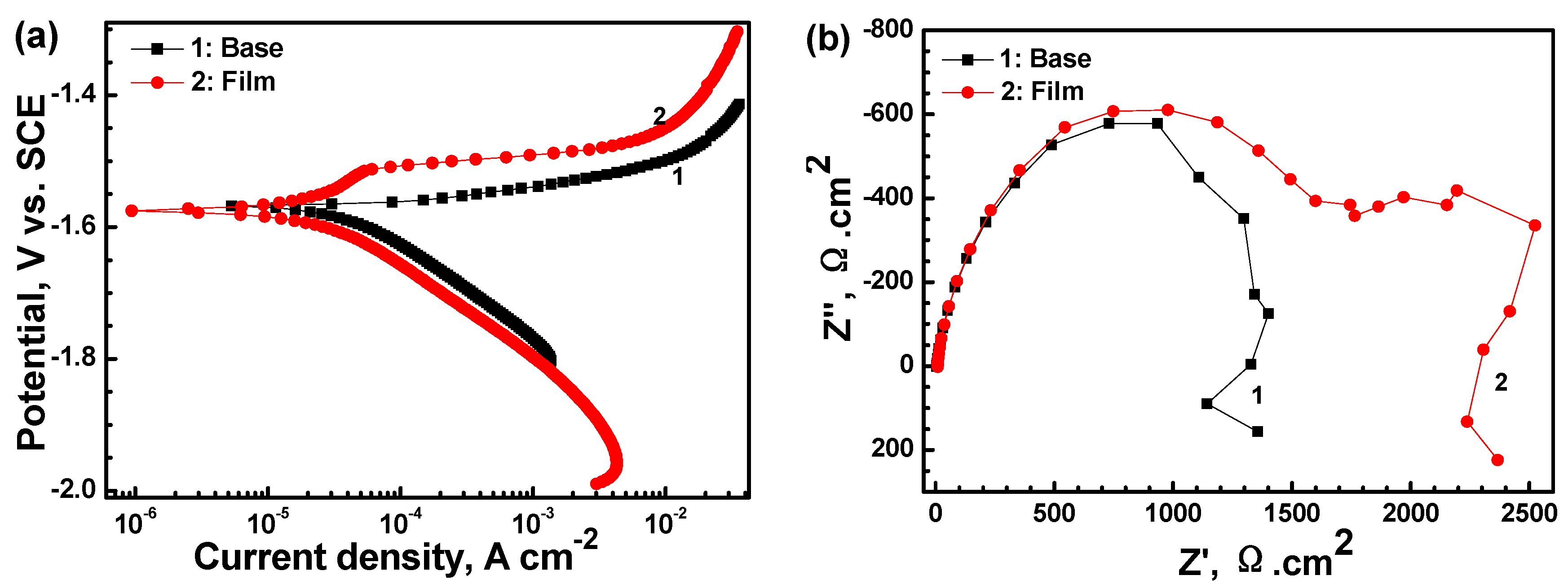
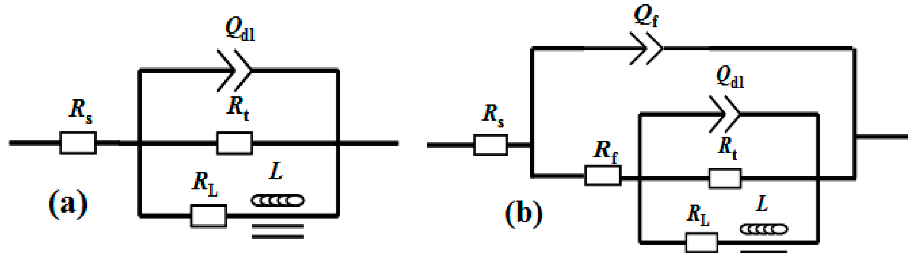
Figure 5 displays the electrochemical tests of the AM60 alloy with and without film in 0.6 M NaCl solution. Three samples were used for the polarization test. Only one polarization curve of the samples was shown, but the degree of uncertainty was given based on the three samples to make the result reliable. The icorr of the substrate slightly decreased from 45.29 ± 1.16 to 24.18 ± 1.62 μA·cm−2 after coating with the film. Moreover, the shape of the two polarization curves exhibit different characteristics. In the curve of the bare alloy, the current density increases sharply above Ecorr, indicating that Ecorr is related to the pitting corrosion. In the case of the coated sample, the current density in the anodic side in the Ecorr range of −1.58 to −1.51 V increases slowly, showing a corrosion inhibiting effect and protective property. However, the corrosion rate increases rapidly when potential increases above −1.50 V, indicating that the aggressive medium already permeated through the crack in the film and that pitting corrosion occurred. The EIS curves show that the Nyquist plot for the substrate only contains two loops: a capacitance loop at high frequency and an inductance loop at low frequency, which are related to the electric double layer at the interface of the substrate and solution and the pit corrosion, respectively. However, the plot obtained for the coated sample is different and consists of three loops (i.e., another medium frequency capacitance loop appears). The high frequency loop is associated with the charge transfer resistance of the film, and the other two loops may be associated with the cracks in the film, as there are many micro-cracks in Figure 1b. The |Z| value of the coated sample is about two times as large as that of the substrate. The equivalent circuit models for the two EIS plots are shown in Figure 6. The fitting results are listed in Table 2. Rs represents the solution resistance. Rt and Qdl represent the charge transfer resistance and electric double layer capacity at the interface of the Mg substrate and electrolyte for Figure 6a, while representing the diffusion process of electrolytes through the cracks of the film for Figure 6b (which is actually the coating cracks resistance, Rcrack). Qf and Rf represent the capacity and resistance of the film, respectively. RL and L represent the inductance resistance and inductance, respectively. From Table 2, it can be seen that the Rf value is larger than Rt. It can be implied that the film has a better dielectric property and charge resistance than the substrate, but the crack is the weak site.
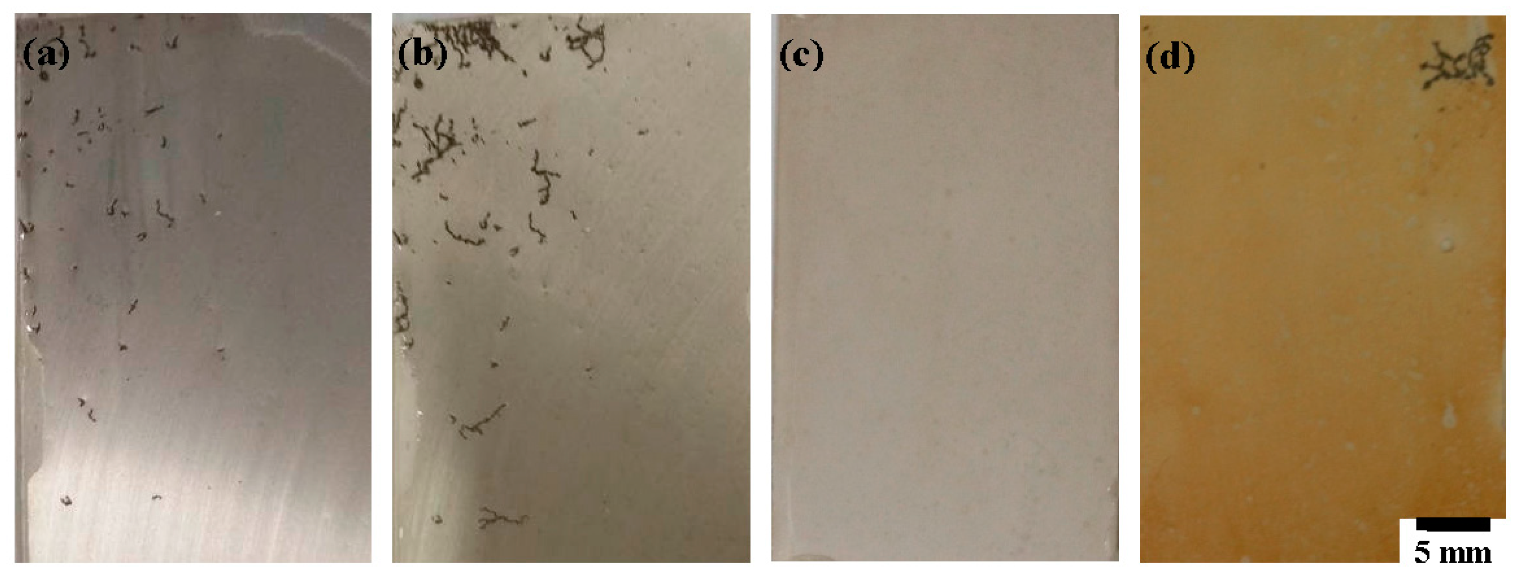
Additionally, an immersion test was also carried out to investigate the corrosion resistance of the film. Figure 7 shows the optical morphology of the AM60 alloy with and without film after 12 and 24 h immersion in 0.6 M NaCl solution, respectively. The macroscopic image of the substrate shows a localized (pitting and filiform) corrosion attack after 12 h immersion (Figure 7a). Conversely, no corrosion is visible on the specimen with film (Figure 7c). After 24 h, the bare alloy undergoes more serious corrosion (Figure 7b), while the majority of the coated sample is not attacked except for the limited areas of filiform corrosion (Figure 7d). However, the color of the film has changed from white gray to yellow. The above results demonstrate that this film can avoid the direct exposure of the substrate to the environment and block the penetration of the solution. As a result, the corrosion initiation time of the coated sample is delayed. However, the color alternation of the film indicates that the corrosion reaction also occurred when the coating comes into contact with a severely aggressive medium. Afterwards, once the electrolyte penetrated through the cracks and got in touch with the substrate, corrosion started from these defects. According to the electrochemical and immersion tests, the composite phosphate film can offer acceptable corrosion protection to AM60, which has the potential to act as an effective and economic anticorrosion film for Mg alloys.
4. Conclusions
In conclusion, a composite PCC containing Ba, Mn, Ca, and Mg has been prepared on AM60 alloy. The composition of the film has been systematically investigated. The film is composed of both amorphous and crystalline phases. The film contains Mg/Mn/Ba-HPO42− precipitates as the primary components, with some Ca/Mg/Ba-PO43− compounds and Ba–containing amorphous phases. The formation mechanism of the phosphatefilm is proposed as follows: (i) dissolution of the AM60 substrate, resulting in a large increase of the OH− concentration and hydrogen evolution; (ii) reduction of H2PO4− to form HPO42−, a minority of which is further reduced to PO43−; (iii) deposition of the more insoluble compounds, Ca/Mg/Ba-PO43−; and (iv) adsorption of the abundant ions from the treating bath to precipitate the Mg/Mn/Ba-HPO42− growth of the film. This composite phosphate film can improve the corrosion resistance of the AM60 alloy, which reduces the corrosion rate of the substrate by half, as well as delays the initiation of localized corrosion. When the bare alloy undergoes serious corrosion, the coated sample is not attacked, except for the limited areas. In others words, this simple chemical conversion method to prepare a film at ambient temperatures within 0.5 h will benefit the protection of Mg alloys for applications in industries.
Acknowledgments
This work was financially supported by the Chunhui Program from the Education Ministry of China (No. Z2015094), the National Natural Science Foundation of China (No. 51501156), the China Postdoctoral Science Foundation funded project (No. 2016M602668), and the Open Research Subject of Key Laboratory of Special Materials and Manufacturing Technology in Sichuan Provincial Universities (No. szjj2016–033).
Author Contributions
Jun Chen and Chao Wang conceived and designed the experiments. Jun Chen and Xiangna Lan performed the experiments. Jun Chen and Qinyong Zhang analyzed the data. Jun Chen wrote the paper. All authors reviewed the manuscript.
Conflicts of Interest
The authors declare no conflict of interest.
References
- Yang, Y.W.; Wu, P.; Wang, Q.Y.; Wu, H.; Liu, Y.; Deng, Y.W.; Zhou, Y.Z.; Shuai, C.J. The enhancement of Mg corrosion resistance by alloying Mn and laser-melting. Materials 2016, 9, 216. [Google Scholar] [CrossRef] [PubMed]
- Gong, F.B.; Shen, J.; Gao, R.H.; Xie, X.; Luo, X. Enhanced corrosion resistance of magnesium alloy by a silane-based solution treatment after an in-situ formation of the Mg(OH)2 layer. Appl. Surf. Sci. 2016, 365, 268–274. [Google Scholar] [CrossRef]
- Mesíková, Ž.; Šulcová, P.; Trojan, M. Synthesis and characterization of newberyite. J. Therm. Anal. Calorim. 2007, 88, 103–106. [Google Scholar] [CrossRef]
- Zimmermann, D.; Munoz, A.G.; Schultze, J.W. Microscopic local elements in the phosphating process. Electrochim. Acta 2003, 48, 3267–3277. [Google Scholar] [CrossRef]
- Banakh, O.; Journot, T.; Gay, P.A.; Matthey, J.; Csefalvay, C.; Kalinichenko, O.; Sereda, O.; Moussa, M.; Durual, S.; Snizhko, L. Synthesis by anodic–spark deposition of Ca- and P-containing films on pure titanium and their biological response. Appl. Surf. Sci. 2016, 378, 207–215. [Google Scholar] [CrossRef]
- Li, G.Y.; Niu, L.Y.; Lian, J.S.; Jiang, Z.H. A black phosphate coating for C1008 steel. Surf. Coat. Technol. 2004, 176, 215–221. [Google Scholar] [CrossRef]
- Phuong, N.V.; Moon, S.; Chang, D.; Lee, K.H. Effect of microstructure on the zinc phosphate conversion coatings on magnesium alloy AZ91. Appl. Surf. Sci. 2013, 264, 70–78. [Google Scholar] [CrossRef]
- Zhou, W.Q.; Tang, W.; Zhao, Q.; Wu, S.W.; Han, E.H. Influence of additive on structure and corrosion resistance of manganese phosphate film on AZ91 magnesium alloy. Mater. Sci. Forum 2011, 686, 176–180. [Google Scholar] [CrossRef]
- Song, Y.W.; Shan, D.Y.; Han, E.H. A novel biodegradable nicotinic acid/calcium phosphate composite coating on Mg-3Zn alloy. Mater. Sci. Eng. C 2013, 33, 78–84. [Google Scholar] [CrossRef] [PubMed]
- Cao, L.; Wang, L.N.; Fan, L.Y.; Xiao, W.J.; Lin, B.P.; Xu, Y.M.; Liang, J.; Cao, B.C. RGDC Peptide-induced biomimetic calcium phosphate coating formed on AZ31 magnesium alloy. Materials 2017, 10, 358. [Google Scholar] [CrossRef] [PubMed]
- Wang, G.X.; Wang, Y.Y.; Wu, S. Preparation and characterization of Zn–Mn phosphate conversion coatings on Mg–Li alloy. Rare Met. Mat. Eng. 2014, 43, 1764–1768. [Google Scholar]
- Chen, X.B.; Zhou, X.; Abbott, T.B.; Easton, M.A.; Birbilis, N. Double–layered manganese phosphate conversion coating on magnesium alloy AZ91D: Insights into coating formation, growth and corrosion resistance. Surf. Coat. Technol. 2013, 217, 147–155. [Google Scholar] [CrossRef]
- Liu, B.; Zhang, X.; Xiao, G.Y.; Lu, Y.P. Phosphate chemical conversion coatings on metallic substrates for biomedical application: A review. Mater. Sci. Eng. C 2015, 47, 97–104. [Google Scholar] [CrossRef] [PubMed]
- Jin, H.; Yang, X.; Peng, W.; Guo, H. Effects of magnetic fields on the phosphate conversion coating of AZ91D magnesium alloy. J. Phys. Conf. Ser. 2010, 200, 082010. [Google Scholar] [CrossRef]
- Chen, Y.G.; Luan, B.L.; Song, G.L.; Yang, Q.; Kingston, D.M.; Bensebaa, F. An investigation of new barium phosphate chemical conversion coating on AZ31 magnesium alloy. Surf. Coat. Technol. 2012, 210, 156–165. [Google Scholar] [CrossRef]
- Liu, F.; Shan, D.Y.; Han, E.H.; Liu, C.S. Barium phosphate conversion coating on die–cast AZ91D magnesium alloy. Trans. Nonferrous Met. Soc. China 2008, 18, 344–348. [Google Scholar] [CrossRef]
- Chen, X.B.; Birbilis, N.; Abbott, T.B. Effect of [Ca2+] and [PO43–] levels on the formation of calcium phosphate conversion coatings on die–cast magnesium alloy AZ91D. Corros. Sci. 2012, 55, 226–232. [Google Scholar] [CrossRef]
- Zhou, W.Q.; Wu, S.W.; Sheng, L.; Li, X. Effect of Ca2+ on structure and corrosion resistance of conversion coating formed on cast AZ91D magnesium alloys. Adv. Mater. Res. 2014, 887–888, 1111–1114. [Google Scholar] [CrossRef]
- Cui, X.F.; Li, Q.F.; Li, Y.; Wang, F.H.; Jin, G.; Ding, M.H. Microstructure and corrosion resistance of phytic acid conversion coatings for magnesium alloy. Appl. Surf. Sci. 2008, 255, 2098–2103. [Google Scholar] [CrossRef]
- Zhou, Y.; Xiong, Q.Y.; Xiong, J.P. The study of a phosphate conversion coating on magnesium alloy AZ91D: I. formation, morphology and composition. Int. J. Electrochem. Sci. 2015, 10, 2812–2824. [Google Scholar]
- Ishizaki, T.; Masuda, Y.; Teshima, K. Composite film formed on magnesium alloy AZ31 by chemical conversion from molybdate/phosphate/fluorinate aqueous solution toward corrosion protection. Surf. Coat. Technol. 2013, 217, 76–83. [Google Scholar] [CrossRef]
- Lee, Y.L.; Chu, Y.R.; Li, W.C.; Lin, C.S. Effect of permanganate concentration on the formation and properties of phosphate/permanganate conversion coating on AZ31 magnesium alloy. Corros. Sci. 2013, 70, 74–81. [Google Scholar] [CrossRef]
- Zhao, Y.B.; Shi, L.Q.; Cui, L.Y.; Zhang, C.L.; Li, S.Q.; Zeng, R.C.; Zhang, F.; Wang, Z.L. Corrosion resistance of silane–modified hydroxyapatite films on degradable magnesium alloys. Acta Metall. Sin. (Engl. Lett.) 2018, 31, 180–188. [Google Scholar] [CrossRef]
- Wang, B.J.; Xu, D.K.; Dong, J.H.; Ke, W. Effect of texture on biodegradable behavior of an as–extruded Mg–3%Al–1%Zn alloy in phosphate buffer saline medium. J. Mater. Sci. Technol. 2016, 32, 646–652. [Google Scholar] [CrossRef]
- Stoch, A.; Jastrzębski, W.; Brożek, A.; Stoch, J.; Szaraniec, J.; Trybalska, B.; Kmita, G. FTIR absorption–reflection study of biomimetic growth of phosphates on titanium implants. J. Mol. Struct. 2000, 555, 375–382. [Google Scholar] [CrossRef]
- Ureña-Amate, M.D.; Boutarbouch, N.D.; Socias-Viciana, M.M.; González-Pradas, E. Controlled release of nitrate from hydrotalcite modified formulations. Appl. Clay Sci. 2011, 52, 368–373. [Google Scholar] [CrossRef]
- Zhang, R.Y.; Cai, S.; Xu, G.H.; Zhao, H.; Li, Y.; Wang, X.X.; Huang, K.; Ren, M.G.; Wu, X.D. Crack self-healing of phytic acid conversion coating on AZ31 magnesium alloy by heat treatment and the corrosion resistance. Appl. Surf. Sci. 2014, 313, 896–904. [Google Scholar] [CrossRef]
- Singh, S.S.; Roy, A.; Lee, B.E.; Ohodnicki, J.; Loghmanian, A.; Banerjee, I.; Kumta, P.N. A study of strontium doped calcium phosphate coatings on AZ31. Mater. Sci. Eng. C 2014, 40, 357–365. [Google Scholar] [CrossRef] [PubMed]
- Woo, M.A.; Kim, T.W.; Paek, M.J.; Ha, H.W.; Choy, J.H.; Hwang, S.J. Phosphate-intercalated Ca–Fe–layered double hydroxides: Crystal structure, bonding character, and release kinetics of phosphate. J. Solid State Chem. 2011, 184, 171–176. [Google Scholar] [CrossRef]
- Liu, G.Y.; Tang, S.W.; Li, D.C.; Hu, J. Self-adjustment of calcium phosphate coating on micro-arc oxidized magnesium and its influence on the corrosion behaviour in simulated body fluids. Corros. Sci. 2014, 79, 206–214. [Google Scholar] [CrossRef]
- Ayala, A.; Fetter, G.; Palomares, E.; Bosch, P. CuNi/Al hydrotalcites synthesized in presence of microwave irradiation. Mater. Lett. 2011, 65, 1663–1665. [Google Scholar] [CrossRef]
- Abdelkader, N.B.H.; Bentouami, A.; Derriche, Z.; Bettahar, N.; de Menorval, L.C. Synthesis and characterization of Mg–Fe layer double hydroxides and its application on adsorption of Orange G from aqueous solution. Chem. Eng. J. 2011, 169, 231–238. [Google Scholar] [CrossRef]
- Esquivel, D.; Cruz-Cabeza, A.J.; Jiménez-Sanchidrián, C.; Romero-Salguero, F.J. Local environment and acidity in alkaline and alkaline-earth exchanged β zeolite: Structural analysis and catalytic properties. Microporous Mesoporous Mater. 2011, 142, 672–679. [Google Scholar] [CrossRef]
- Song, Y.W.; Shan, D.Y.; Chen, R.S.; Zhang, F.; Han, E.H. A novel phosphate conversion film on Mg–8.8Li alloy. Surf. Coat. Technol. 2009, 203, 1107–1113. [Google Scholar] [CrossRef]
- Wu, L.P.; Zhao, L.; Dong, J.H.; Ke, W.; Chen, N. Potentiostatic conversion of phosphate mineral coating on AZ31 magnesium alloy in 0.1 M K2HPO4 solution. Electrochim. Acta 2014, 145, 71–80. [Google Scholar] [CrossRef]
- Chen, J.; Song, Y.W.; Shan, D.Y.; Han, E.H. In situ growth of Mg–Al hydrotalcite conversion film on AZ31 magnesium alloy. Corros. Sci. 2011, 53, 3281–3288. [Google Scholar] [CrossRef]
- Wan, T.T.; Liu, Z.X.; Bu, M.Z.; Wang, P.C. Effect of surface pretreatment on corrosion resistance and bond strength of magnesium AZ31 alloy. Corros. Sci. 2013, 66, 33–42. [Google Scholar] [CrossRef]
- Zhang, W.; Tian, B.; Du, K.Q.; Zhang, H.X.; Wang, F.H. Preparation and corrosion performance of PEO coating with low porosity on magnesium alloy AZ91D in acidic KF system. Int. J. Electrochem. Sci. 2011, 6, 5228–5248. [Google Scholar]
- Nabiyouni, M.; Ren, Y.F.; Bhaduri, S.B. Magnesium substitution in the structure of orthopedic nanoparticles: A comparison between amorphous magnesium phosphates, calcium magnesium phosphates, and hydroxyapatites. Mater. Sci. Eng. C 2015, 52, 11–17. [Google Scholar] [CrossRef] [PubMed]
Figure 1.
SEM morphology of different films: (a,b) the film formed by the optimum process and (c,d) the film for comparison.
Figure 1.
SEM morphology of different films: (a,b) the film formed by the optimum process and (c,d) the film for comparison.

Figure 2.
FTIR spectrum of the film.
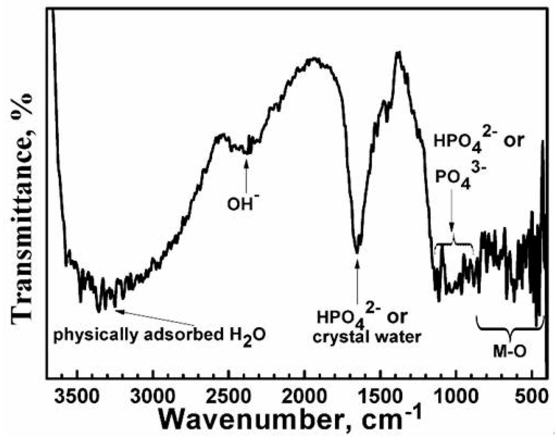
Figure 3.
XPS analysis of the film after 30 s etching: (a) Mn 2p; (b) Ba 3d; (c) Ca 2p; (d) Mg 1s; (e) O 1s; and (f) P 2p.
Figure 3.
XPS analysis of the film after 30 s etching: (a) Mn 2p; (b) Ba 3d; (c) Ca 2p; (d) Mg 1s; (e) O 1s; and (f) P 2p.

Figure 4.
XRD spectrum of the film.

Figure 5.
(a) Polarization curves and (b) Nyquist plots of the AM60 alloy with and without film immersed in 0.6 M NaCl solution.
Figure 5.
(a) Polarization curves and (b) Nyquist plots of the AM60 alloy with and without film immersed in 0.6 M NaCl solution.

Figure 6.
Equivalent circuits for the EIS spectra of: (a) the AM60 substrate and (b) the sample coated with film immersed in 0.6 M NaCl solution.
Figure 6.
Equivalent circuits for the EIS spectra of: (a) the AM60 substrate and (b) the sample coated with film immersed in 0.6 M NaCl solution.

Figure 7.
Optical morphology of (a,b) the AM60 substrate and (c,d) the sample coated with film after immersion tests for 12 h and 24 h in 0.6 M NaCl, respectively.
Figure 7.
Optical morphology of (a,b) the AM60 substrate and (c,d) the sample coated with film after immersion tests for 12 h and 24 h in 0.6 M NaCl, respectively.


Table 1.
The content of various elements in the film tested by EDS.
| Element | C | O | Mg | P | Ca | Mn | Ba | Al |
|---|---|---|---|---|---|---|---|---|
| Content (at %) | 3.31 | 58.81 | 13.93 | 11.47 | 0.97 | 4.96 | 4.58 | 20.7 |
Table 2.
Fitting results of the EIS spectra for the AM60 alloy with and without film immersed in 0.6 M NaCl solution.
Table 2.
Fitting results of the EIS spectra for the AM60 alloy with and without film immersed in 0.6 M NaCl solution.
| Sample | Rs (Ω·cm2) | Y0 (μΩ−1·cm−2·s−1) | n | Rf (Ω·cm2) | Y0’ (μΩ−1·cm−2·s−1) | n’ | Rt (Ω·cm2) | L (kH·cm2) | RL (Ω·cm2) |
|---|---|---|---|---|---|---|---|---|---|
| Base | 15.9 | - | - | - | 19.08 | 0.87 | 870 | 557 | 645 |
| Film | 19.04 | 10.46 | 0.82 | 1162 | 7.48 | 0.88 | 582 | 219 | 2519 |
© 2018 by the authors. Licensee MDPI, Basel, Switzerland. This article is an open access article distributed under the terms and conditions of the Creative Commons Attribution (CC BY) license (http://creativecommons.org/licenses/by/4.0/).
Share and Cite
MDPI and ACS Style
Chen, J.; Lan, X.; Wang, C.; Zhang, Q. The Formation Mechanism and Corrosion Resistance of a Composite Phosphate Conversion Film on AM60 Alloy. Materials 2018, 11, 402. https://doi.org/10.3390/ma11030402
AMA Style
Chen J, Lan X, Wang C, Zhang Q. The Formation Mechanism and Corrosion Resistance of a Composite Phosphate Conversion Film on AM60 Alloy. Materials. 2018; 11(3):402. https://doi.org/10.3390/ma11030402
Chicago/Turabian StyleChen, Jun, Xiangna Lan, Chao Wang, and Qinyong Zhang. 2018. "The Formation Mechanism and Corrosion Resistance of a Composite Phosphate Conversion Film on AM60 Alloy" Materials 11, no. 3: 402. https://doi.org/10.3390/ma11030402
Note that from the first issue of 2016, this journal uses article numbers instead of page numbers. See further details here.