Fatigue Life Prediction for Transverse Crack Initiation of CFRP Cross-Ply and Quasi-Isotropic Laminates


1
Department of Applied Mechanics and Aerospace Engineering, Waseda University, Tokyo 169-8555, Japan
2
Kagami Memorial Research Institute for Material Science and Technology, Waseda University, Tokyo 169-0051, Japan
*
Author to whom correspondence should be addressed.
Materials 2018, 11(7), 1182; https://doi.org/10.3390/ma11071182
Submission received: 4 June 2018
/
Revised: 2 July 2018
/
Accepted: 5 July 2018
/
Published: 10 July 2018
(This article belongs to the Special Issue Carbon Fiber Reinforced Polymers)
Abstract
:Carbon fiber reinforced plastic (CFRP) laminates are used as main structural members in many applications. Transverse cracks that form in 90° layers of CFRP laminates are mostly initial damage in the case where tensile loading is vertically applied to the 90° layers of CFRP laminates, and they are the origin of more serious damage of delamination and fiber breakage. It is thus important to predict quantitatively the transverse crack initiation of CFRP laminates subjected to cyclic loading to ensure the long-term reliability of the laminates. The initiation and multiplication behaviors of transverse cracks strongly depend on the laminate configuration, thickness, and thermal residual stress. Therefore, a model based on the Walker model was proposed to predict transverse crack initiation in CFRP cross-ply and quasi-isotropic laminates under cyclic loading in the present study. The usefulness of the proposed model was verified with 10 different CFRP laminates formed from four different prepregs with epoxy resin matrices. The analysis results were in good agreement with experimental results. The fatigue life was expressed with three constants, which related to the fatigue strength reduction, the normalized fatigue strength at N = 1 cycle, and the contribution of stress amplitude to the fatigue life, and they are independent of the laminate configuration.
1. Introduction
Carbon fiber reinforced plastic (CFRP) laminates are used as the main structural members of aircraft, automobiles, wind turbine blades, tidal turbine blades, and jet-engine fan blades. The damage tolerance strain of CFRP laminates in the design of airplanes is determined based on the compression-after-impact strength. However, the safe-life design should be considered for more precise design and long-term durability of CFRP structures in other applications, such as automobiles in various environments, where the structures are not necessarily inspected and repaired in controlled operations, like those implemented for airplanes. The main forms of the damage mechanism of CFRP laminates are fiber-matrix debonding, intralaminar and interlaminar matrix cracks, and fiber breakage, which propagate while interacting with each other, finally, resulting in the rupture of the laminates [1], and many fatigue life prediction models, which are based on cumulative damage theory [2], strain energy density [3], statistical approach [4], constant fatigue diagram [5], and damage mechanics [6], have been proposed so far. A transverse crack in 90° layers of CFRP laminate is mostly initial damage and is the origin of more serious damage of delamination and fiber breakage. It is thus essential to evaluate quantitatively the fatigue life to transverse crack initiation of CFRP laminates for the use of the laminates as structural members.
The multiplication and propagation behaviors of transverse cracks in CFRP laminates have been quantitatively evaluated through experiments and analysis under static and fatigue loading [7,8,9,10,11,12]. The initiation behavior of transverse cracks under static loading has also been evaluated [7,8,13,14,15,16]. Recently, the effects of initial defects on crack initiation were evaluated by Maragoni et al. [17] and Aratama et al. [18]. However, there have been few studies on the prediction of transverse crack initiation in CFRP laminates under fatigue loading because it is difficult to experimentally or analytically evaluate the initiation behavior of a transverse crack under fatigue loading. Henaff-Gardin and Lafarie-Frenot [19] experimentally showed that the fatigue life to transverse crack initiation can be represented by a power law function of the normalized energy release rate, the maximum energy release rate of fatigue loading for the critical energy release rate, associated with the transverse crack formation. Ogi and Yashiro [20] proposed a probabilistic slow crack growth model with which to predict the initiation and multiplication behavior of transverse cracks in CFRP laminates under fatigue loading. Quaresimin et al. [21,22] evaluated the fatigue crack initiation in unidirectional and off-axis laminates with local hydrostatic stress or local maximum principal stress. Recently, the authors proposed a method of predicting the fatigue life to transverse crack initiation by applying a power law function that expresses the relationship between the transverse crack multiplication rate and the energy release rate range associated with transverse crack formation [23]. In addition, we showed quantitatively that the fatigue life to transverse crack initiation in cross-ply laminates can be predicted using the fatigue properties obtained from the S–N curve of a unidirectional laminate in transverse direction, 90° unidirectional laminate. [24,25].
The initiation and multiplication of the transverse cracks in CFRP laminates strongly depend on the stacking sequence of laminates, dimensions, thermal residual stress, and the stress ratio. In some cases, transverse cracks pass through the width direction of the laminates; however, in other cases, short transverse cracks multiply at the edges of the laminates because of free-edge effects. As described above, a model that can be used to evaluate the initiation of transverse cracks that vary under such effects in the case of fatigue loading has not yet been proposed. Therefore, the present paper proposes a model based on fracture mechanics with which to evaluate the fatigue life to transverse crack initiation considering these effects and verifies the usefulness of the model using various types of cross-ply [0m/90n]s and quasi-isotropic [45/0/–45/90]s laminates.
2. Prediction Model for Transverse Crack Initiation
The present paper proposes a model with which to predict transverse crack initiation in cross-ply and quasi-isotropic laminates with the application of cyclic loading. A thermal residual stress is generated in the laminates because of the difference in the thermal expansion coefficients of the plies and the difference between the test and curing temperatures. A tensile thermal residual stress is thus generated in the 90° layers of the laminates at room temperature. Therefore, even if mechanical loading with a constant stress ratio of R = 0.1 was applied to the specimens, the stress ratio applied to the 90° layers of the laminates differed depending on the laminate configuration and the applied stress level resulting from the thermal residual stress. In addition, the stress at the transverse crack initiation was affected by a size effect [26]. To evaluate the transverse crack initiation, the effects of the stress ratio and laminate thicknesses must be considered.
Models, such as the Gerber model, Goodman model, and Soderberg model, have been proposed to evaluate the effect of the stress ratio on the prediction of the fatigue life [27]. Walker [28] proposed an equation with which to evaluate the effect of the stress ratio on fatigue crack propagation in metallic materials:
where a is the crack length, N is the number of loading cycles, and K is the stress intensity factor. ΔK is the range of the stress intensity factor (ΔK = Kmax − Kmin), while A, m, and γ are constants obtained from experimental results. Because the growth of a fatigue crack is controlled by Kmax in brittle materials and by ΔK in ductile materials [29], fatigue crack growth in many materials is generally controlled by both Kmax and ΔK, as shown in Equation (2). Hojo et al. [30,31] evaluated the effect of the stress ratio on mode-I and mode-II delamination growth in CFRP laminates using the energy release rate. It is more common to use the energy release rate, G, because a CFRP is an inhomogeneous material composed of fibers and a matrix resin. In linear fracture mechanics, the relationship between the energy release rate and stress intensity factor is expressed as G = HK2, where H is a constant. Equation (2) can thus be expressed according to the strain energy:
Here, the transverse crack multiplication behavior in CFRP laminates under fatigue loading is expressed by:
where D is the transverse crack density, which is defined as the number of transverse cracks, n, per gauge length, L (=n/L). F and β are constants obtained in experiments. Gteq is the equivalent energy release rate associated with the transverse crack formation. The subscript, t, indicates a transverse crack. Gti is the energy release rate when the transverse crack initiates under static tensile loading. The energy release rate associated with the transverse crack formed in CFRP laminates is calculated using the model proposed by Nairn [8,14] as:
Considering the thermal residual stress, the stress applied on the 90° layers in the laminates is expressed using the law of mixtures:
where the superscripts (90) and (S) respectively represent 90° layers and the sublaminate adjacent to the 90° layers. E0 and EA are the Young’s moduli of the composite in the axial direction of the 90° laminate and sublaminate, respectively; σ0 and ε0 are the stress and strain in the composites, respectively; Δα is the difference in the thermal expansion coefficient between the transverse and longitudinal directions of unidirectional laminates, Δα = αT − αA; T is the difference between the specimen temperature and stress-free temperatures; C3 is a constant that depends on the material properties and ply thickness; b and h are the one-sided thickness of the sublaminate and half the thickness of the cross-ply or quasi-isotropic laminates, respectively; and Y(D) is a function that depends on the transverse crack density.
The first transverse crack formation is asymptotically predicted from the transverse crack multiplication behavior expressed by Equation (5). The number of cycles when the transverse crack density increases from D to 2D is expressed based on Equation (5) as:
In the region of low transverse crack density in the early stage of fatigue, the energy release rate associated with transverse crack formation is constant. Experimental evidence has shown that the increase in the transverse crack density is proportional to the number of cycles in this region [24]. When the density in the transverse crack initiation is defined as 1/L, such that there is one transverse crack in the gauge length L, the number of cycles to transverse crack initiation is equal to the number of cycles that it takes for the transverse crack density to increase from 1/L to 2/L. Therefore, the number of cycles to transverse crack initiation is obtained by substituting D = 1/L into Equation (8):
Here, the normalized energy release rate at a transverse crack density, D = 1/L, can be expressed based on Equation (6) as:
Here, σmax, σa, and σti are the maximum stress of the applied cyclic loading, the stress amplitude of the applied cyclic loading, and the initiation stress of the transverse crack under tensile loading, respectively. The normalized energy release rate is expressed using only the stress applied in the 90° layers. The shape function of the laminates is erased by normalizing the energy release rate and can be evaluated regardless of the laminate size. Finally, the transverse crack initiation can be predicted by substituting Equation (10) into Equation (9):
Here, η and λ are constants obtained in experiments. Further, Equation (11) can be expressed as Equation (12):
In terms of a logarithmic graph of the relationship between the normalized stress and the fatigue life to transverse crack initiation, λ is the slope and η is the intercept of the graph. That is, the physical meanings of λ and η are the parameters related to the fatigue strength reduction in the transverse crack initiation and the normalized fatigue strength in the transverse crack initiation at N = 1 cycle, respectively. In addition, the fatigue properties of the material are generally dominated by maximum stress, σmax, in the case of brittle materials, and by the stress amplitude, σa, in the case of ductile materials. Therefore, γ is a parameter indicating the contribution of the stress amplitude on the fatigue life to the transverse crack initiation in the samples. Because Equations (11) and (12) are expressed using only the stress applied in 90° layers, the constants, η and λ, can be obtained from the S–N curve for the transverse crack initiation of arbitrary laminates or the S–N curve of unidirectional 90° laminates. The fatigue life of transverse crack initiation in cross-ply and quasi-isotropic CFRP laminates can then be predicted. The proposed model is verified by reorganizing data of experiments previously carried out by the authors [24,32,33,34,35,36].
3. Experiments
3.1. Specimens
Ten CFRP laminates were formed from four prepregs with epoxy resin matrices: T800S/2592 with fiber volume fractions (Vf) of 68% and 61%, T800S/3900-2B with Vf = 56%, and T800H/3631 with Vf = 57%. The T800S/3900-2B prepreg was coated with a toughened layer. The cured ply thickness was approximately 80 μm, 110 μm, 190 μm, and 140 μm, respectively. The specimens were cut out from 300 mm × 300 mm laminates using a diamond saw. Figure 1 is a schematic illustration of a specimen, while Table 1 lists the stacking sequences of the laminates and the curing temperatures and dimensions of the specimens. The mechanical properties of each prepreg are listed in Table 2. The edge surfaces of the specimens were polished with emery paper and finished by buffing with diamond powder with particle sizes less than 6 μm. After polishing the specimens, it was confirmed that transverse cracks were not generated with an optical microscope before the tests.
3.2. Static Tensile Tests
The mechanical properties and the stress of the transverse crack initiation, σti, of the specimens were obtained in static tensile tests. The tensile speed was 0.5 mm/min. The damage to the specimen was examined by ex-situ observation employing soft X-ray photography (Softex Corp., Tokyo, Japan) and optical microscopy (Olympus Corp., Tokyo, Japan). For soft X-ray photography, a contrast agent of zinc iodide was applied from the edge surfaces of the specimens. At this time, a load sufficiently smaller than that causing the transverse crack was applied to the specimen so that the contrast agent easily penetrated the specimen. The irradiation conditions for soft X-ray photography differ depending on the thickness of the specimen. For example, when observing the specimen with the thickness of 1 mm, the irradiation condition was a voltage of 40 kV, a current of 1 mA, and an irradiation time of 15 s. The developed X-ray photographs were scanned to a computer, and the initiation and growth of the damage was observed. The specimen was removed from the testing machine to observe the damage, and the transverse crack initiation was evaluated by applying a tensile load step by step. Until a transverse crack initiated, the load was applied at 5% increments of the tensile strength and the specimen was observed. After the transverse crack occurred, the load was applied at 10% increments of the tensile strength and it was observed. The observable or significant relaxation effects by removing the specimen were not found.
3.3. Tensile Fatigue Testes
Tensile fatigue tests were carried out under load control using a hydraulic fatigue testing machine (Shimadzu Corp., Kyoto, Japan). All tests were run at a stress ratio of R = 0.1 and a frequency f = 5 or 100 Hz. The fatigue test conditions are listed in Table 3. σmax is the maximum stress of the applied loading. As demonstrated in previous studies [32,37], the effect of the frequency on damage growth is weak for these test conditions. The fatigue tests were interrupted at arbitrary loading cycles based on N = 1.0 × 10n, 2.0 × 10n, 5.0 × 10n cycles as a standard, and the initiation and multiplication behavior of transverse cracks formed in the specimens was evaluated by ex-situ observation employing soft X-ray photography and optical microscopy, like the static tensile tests. For detailed observation of the transverse crack formation, atomic force microscopy (AFM, Bruker Corp., Billerica, MA, USA) and scanning electron microscopy (SEM, Hitachi, Ltd., Tokyo, Japan) were used.
4. Damage Observation
4.1. Damage Growth Behavior Observed Employing Soft-X ray Photography
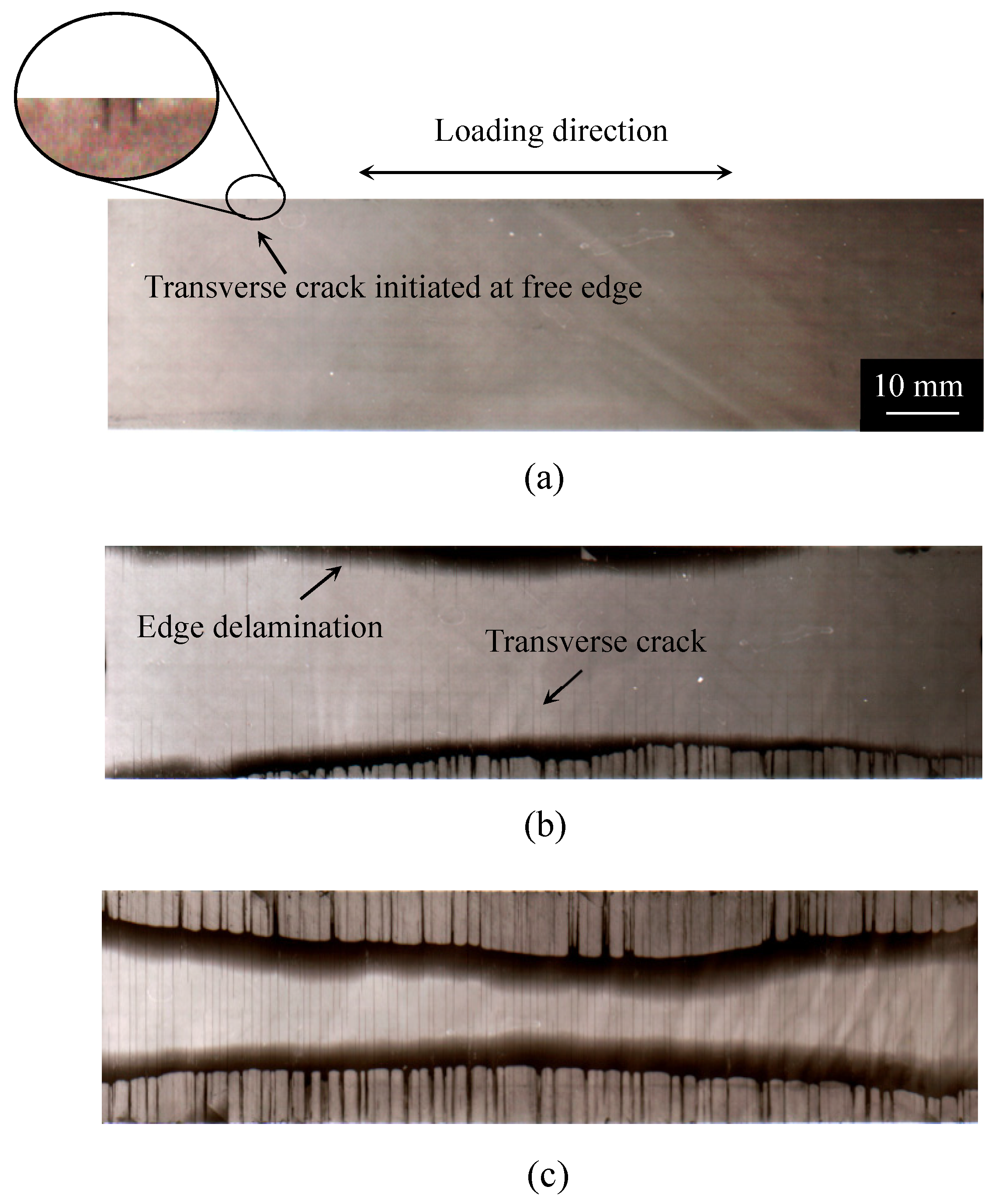
Figure 2, Figure 3 and Figure 4 show the damage growth behavior observed employing soft X-ray photography in the cross-ply [0/902]s laminate formed from the T800H/3631 prepreg, the cross-ply [02/9012]s laminate formed from the T800S/2592 prepreg, and the quasi-isotropic [45/0/–45/90]s laminates formed from the T800H/3631 prepreg, respectively. In the cross-ply [0/902]s laminates of Figure 2, the transverse cracks that formed at the specimen edges rapidly grew in the width direction and multiplied in the specimen with an increasing number of loading cycles. Finally, local delamination originating from the transverse cracks and splitting occurred. In the cross-ply [02/9012]s laminates of Figure 3, the transverse cracks that formed at the specimen edges rapidly grew in the width direction. Unlike the case in Figure 2, local delamination propagated in the longitudinal direction after some transverse cracks formed. The transverse crack density was, therefore, much lower than that in Figure 2. The local delamination initiated and propagated more easily than in the thinner cross-ply laminates because a larger interlaminar shear stress developed at the transverse crack tip in the thick cross-ply laminates. The damage growth behavior of the cross-ply [0/906]s laminates formed from the same prepreg of the cross-ply [02/9012]s laminates was similar to the cross-ply [0/902]s laminates as shown in Figure 2 [34,35]. However, in the quasi-isotropic laminates shown in Figure 4, short transverse cracks initiated and saturated at the specimen edge, and then propagated in the width direction. Afterwards, delamination initiated in the interlaminar areas of the 90°/−45° plies at the specimen edges because of the stress concentration at the transverse crack tip. After the delamination grew in the longitudinal direction at the specimen edges, it propagated in the specimen width direction. The short transverse cracks and edge delamination were due to the free-edge effect, which is a stress singularity at the free edge caused by the difference in the Poisson’s ratios of each lamina. The damage growth behavior greatly differed depending on the laminate configuration. Since the initiation and growth of transverse cracks are greatly affected by the free edge effect, it is important to consider the influence of the free edge effect.
4.2. Observation of Transverse Crack Initiation and Growth
Figure 5 shows the growth process of a micro crack originating from the initial defects in the cross-ply [02/9012]s laminates formed from the T800S/2592, Vf = 68% prepreg. The left and right images of the upper part of Figure 5 were observed using AFM. The other photographs in Figure 5 were observed using optical microscopy. The AFM samples were prepared by the following procedure. First, a replica film, acetyl cellulose film, which was applied with methyl acetate and attached to the edge surface of the specimen, and the micro damage of the specimen was transferred. The transferred film was attached to a sample stage and the surface was observed. The transfer resolution was approximately 100 Å. The initial defects are shown in Figure 5a. In addition, initial defects, with lengths of approximately 10 μm and depths of approximately 100 nm, were observed employing AFM. The micro cracks propagated in the thickness direction from these initial defects. The micro cracks were observed at N = 1.0 × 10⁴ cycles using an optical microscope. The micro cracks generally initiated near the 0°/90° interlaminar area and propagated to the opposite side.
Figure 6 presents SEM photographs of a micro crack in the cross-ply [0/906]s laminates formed from the T800S/2592, Vf = 68% prepreg. In the SEM observation, the specimen was removed from the fatigue testing machine, and the edge surface of the specimen was coated with a platinum thin film. Then, the edge surface was observed under the condition of 20 kV. The micro crack propagated along the interface between the fiber and matrix under fatigue loading, whereas it propagated in the matrix under static tensile loading. Similar behavior was observed in the material system used in this study. In this study, a crack that passed through the thickness direction of the 90° layers in the laminates and could be observed employing soft X-ray photography was defined as a transverse crack.
5. Prediction Results of Transverse Crack Initiation under Fatigue Loading
Figure 7a–d presents the evaluation results obtained using the proposed model for the fatigue life prediction of the transverse crack initiation of laminates formed using each prepreg, T800S/2592 with Vf = 68% and 61%, T800S/3900-2B with Vf = 56%, and T800H/3631 with Vf = 57%, respectively. The plots in Figure 7 are the experimental data obtained from the fatigue tests using the laminates shown in Table 1. In the cross-ply and the quasi-isotropic laminates, the damage observation was repeatedly done, and the number of loading cycles in which a transverse crack was observed for the first time was measured. In the 90° unidirectional laminates, the number of cycles to the fracture was measured. The solid lines in the figure are the fitting curve obtained from Equation (11). The constants in Equation (11) for the prepregs of T800S/2592 with Vf = 68% and 61%, T800S/3900-2B with Vf = 56%, and T800H/3631 with Vf = 57% were η = 1.09 × 10⁻³ and λ = −18.8; η = 1.33 × 10⁻² and λ = −14.5; η = 8.99 × 10⁻⁵ and λ = −25.4; and η = 2.64 × 10⁻⁵ and λ = −21.3, respectively. In this study, γ = 0.5, which corresponds to the Smith–Watson–Topper model [38], was used. The fatigue life of transverse crack initiation can be evaluated with a curve regardless of the laminate configuration. Figure 8 combines Figure 7a–d. Similar tendencies were observed for the transverse crack initiation with the various combinations of carbon fibers and epoxy resin used in this study; however, slight relative merits were observed among the prepregs.
Figure 9a–d shows the relationship between the initial maximum strain and the fatigue life to transverse crack initiation using the constants obtained from Figure 7. The initial maximum strain was calculated using Equation (7) because the values of strain are useful for the design of composite structures. The analytical results obtained using the proposed model are in good agreement with the experimental results. These findings indicate that the proposed model successfully considers the effects of the stress ratio, laminate thickness, and laminate configuration on transverse crack initiation under fatigue loading.
A tensile thermal residual stress was applied to the 90° layers in cross-ply and quasi-isotropic laminates at the test temperature. Thus, the stress ratio in the 90° layers, where the transverse crack initiates, varied depending on the load level applied to the specimen even if a mechanical stress with a stress ratio of R = 0.1 was applied. Nevertheless, the prediction results are in good agreement with the experimental results. From the results presented in Figure 9a, the fatigue life to the transverse crack initiation of [0/906]s laminates was approximately 30 times longer than that of [02/9012]s laminates despite the equivalent stress conditions of these laminates. These results indicate that the proposed model successfully considers the effect of the laminate thickness on the transverse crack initiation. In addition, the results in Figure 9a–c demonstrate that the fatigue life of the transverse crack initiation in cross-ply laminates can be predicted using the S–N curve of the 90° unidirectional laminates. The results in Figure 9d indicate that the fatigue life of the transverse crack initiation can be predicted for the quasi-isotropic laminates that cause the edge cracks as shown in Figure 4.
6. Discussion
6.1. Effect of Laminate Thickness
We consider the fatigue life of the transverse crack initiation of cross-ply [0/906]s laminates to be approximately 30 times longer than that of cross-ply [02/9012]s laminates, as observed in Figure 9a, because of the constraint effect of adjacent layers [26,39]. Figure 5 and Figure 6 demonstrate that a micro crack initiated near adjacent plies in the 90° layers and propagated to the opposite side in the 90° layers along the interface between the fiber and matrix under fatigue loading. During the micro crack propagation, the crack opening displacement of the micro crack in the 90° layers was smaller because of the restraint of the adjacent ply, the 0° ply, in the thinner laminates. Therefore, the energy release rate for the micro crack propagation is thought to decrease in the thinner laminates. Consequently, more cyclic loadings were required in the thinner laminates such that the micro cracks passed through the thickness direction in the 90° layers. However, the transverse crack in the quasi-isotropic laminates initiated at the low strain level even though the quasi-isotropic laminates had thin 90° plies. This initiation occurred because of the small constraint effect of −45° plies of adjacent layers and the free-edge effect. For the proposed model, the shape function of the laminates was erased by normalizing the energy release rate in Equation (10). It is thus thought that the transverse crack initiation can be evaluated regardless of the laminate thickness.
6.2. Free-Edge Effects
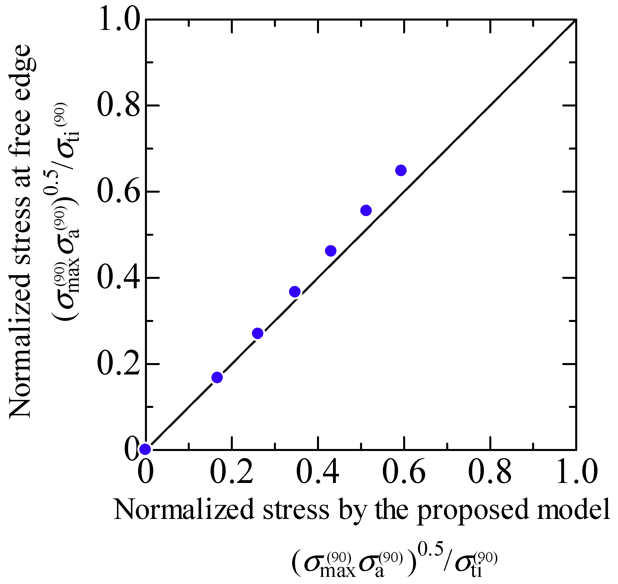
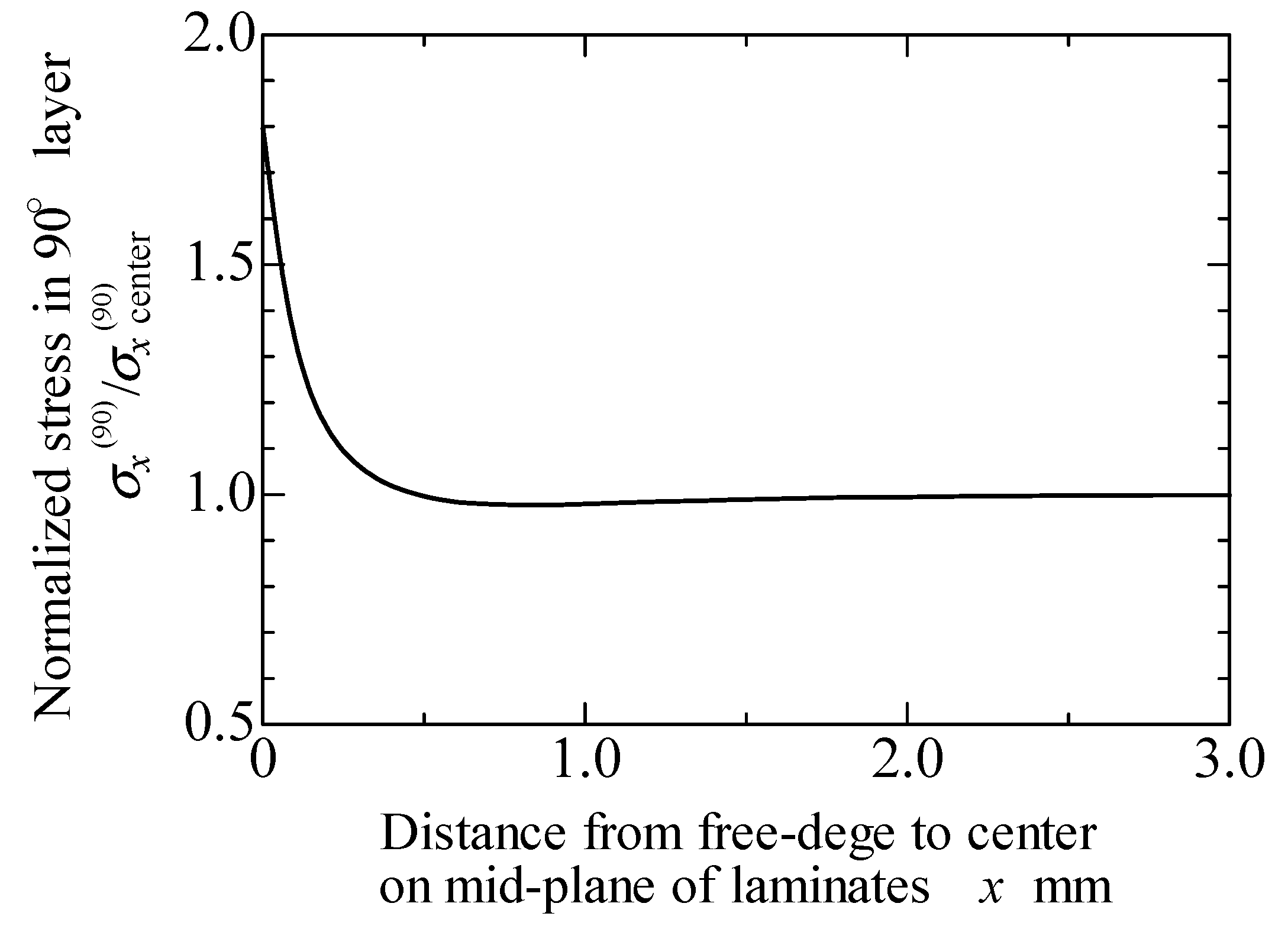
As mentioned above, the stress singularity due to the free-edge effect affected the initiation of transverse cracks in the quasi-isotropic laminates. As observed in Figure 2, Figure 3 and Figure 4, the transverse crack in the cross-ply laminates passed through the width direction immediately after it formed at the specimen edge, whereas the transverse crack in the quasi-isotropic laminates first multiplied at the specimen edge and then gradually propagated in the width direction. The model proposed in this study did not consider the stress singularity at the specimen edges. Nevertheless, the analytical results are in good agreement with the experimental results. Figure 10 presents a half model of the quasi-isotropic laminates produced using the commercial finite element code, COMSOL (a product name). A quadratic hexahedral element was used in the model. The number of elements was 19,200, and the minimum element size was 2.5 μm. Tensile loading was applied in the longitudinal direction. The edge surfaces of the specimen were well polished, and the surface roughness was Ra = 0.5 μm or less. The layers of the laminate were assumed as homogeneous orthotropic materials, and the stress was calculated by linear elastic analysis. It is thought that the stress at the edge surface of the FEM model is estimated higher than the actual. Figure 11 shows the relationship between the normalized normal stress distribution applied in the 90° layers of the laminates in the loading direction and the distance from the free edge when the loading corresponding to the stress of the transverse crack initiation under static tensile loading, σti, was applied to the model. The stress at the free edges was 1.8 times that inside. Figure 12 compares the normalized stress at the free edge, calculated through finite element analysis, with that calculated using the law of mixtures presented as Equation (7). The effect of the stress singularity at the free edge was canceled out by normalizing it with σti(90). It is thus thought that the initiation of a transverse crack can be evaluated using Equation (11) for quasi-isotropic laminates.
7. Conclusions
A model was proposed to predict transverse crack initiation in cross-ply and quasi-isotropic CFRP laminates under fatigue loading based on the Walker model. It was shown that the fatigue life can be predicted with three independent constants of the proposed model, λ, η, and γ, which are the parameters with physical meanings related to the fatigue strength reduction in the transverse crack initiation, the normalized fatigue strength in the transverse crack initiation at N = 1 cycle, and the contribution of stress amplitude on the fatigue life to the transverse crack initiation, respectively. The analytical results obtained using the proposed model were in good agreement with the experimental results, and the usefulness of the model was shown to predict the fatigue life to transverse crack initiation in cross-ply and quasi-isotropic CFRP laminates under tensile fatigue loading.
Author Contributions
Conceptualization, A.H.; Methodology, A.H.; Validation, A.H.; Formal Analysis, A.H.; Investigation, A.H.; Writing-Original Draft Preparation, A.H.; Writing-Review & Editing, A.H. and H.K.; Supervision, H.K.
Funding
This research received no external funding.
Conflicts of Interest
The authors declare no conflict of interest.
References
- Galiotis, C.; Koimtzoglou, C. The effect of the interface on the fatigue performance of fibre composites. In Fatigue of Composites, Science and Technology of the Fatigue Response of Fibre-Reinforced Plastics; Harris, B., Ed.; Woodhead Publishing Limited: Oxford, UK, 2003; pp. 147–172. ISBN 978-1-85573-608-5. [Google Scholar]
- Hashin, Z. Cumulative damage theory for composite materials: Residual life and residual strength methods. Compos. Sci. Technol. 1985, 23, 1–19. [Google Scholar] [CrossRef]
- Ellyin, F.; El-Kadi, H. A fatigue failure criterion for fiber reinforced composite laminae. Compos. Struct. 1990, 15, 61–74. [Google Scholar] [CrossRef]
- Daio, X.; Ye, L.; Mai, Y.-W. Statistical fatigue life prediction of cross-ply composite laminates. J. Compos. Mater. 1997, 31, 1442–1460. [Google Scholar] [CrossRef]
- Gathercole, N.; Reiter, H.; Adam, T.; Harris, B. Life prediction for fatigue of T800/5245 carbon-fibre composites: I. Constant-amplitude loading. Int. J. Fatigue 1994, 16, 523–532. [Google Scholar] [CrossRef]
- Kawai, M.; Yajima, S.; Hachinohe, A.; Takano, T. Off-axis fatigue behavior of unidirectional carbon fiber-reinforced composites at room and high temperatures. J. Compos. Mater. 2001, 35, 545–576. [Google Scholar] [CrossRef]
- Berthelot, J.M. Transverse cracking and delamination in cross-ply glass-fiber and carbon-fiber reinforced plastic laminates: Static and fatigue loading. Appl. Mech. Rev. 2003, 56, 111–147. [Google Scholar] [CrossRef]
- Nairn, J.A. Matrix microcracking in composites. In Comprehensive Composite Materials: Polymer Matrix Composites; Kelly, A., Zweben, C., Eds.; Elsevier Science Ltd.: Oxford, UK, 2000; Volume 2, pp. 403–432. ISBN 0-08-043720-6. [Google Scholar]
- Vinogradov, V.; Hashin, Z. Probabilistic energy based model for prediction of transverse cracking in cross-ply laminates. Int. J. Solids Struct. 2005, 42, 365–392. [Google Scholar] [CrossRef]
- Talreja, R. Fatigue of polymer matrix composites. In Comprehensive Composite Materials: Polymer Matrix Composites; Kelly, A., Zweben, C., Eds.; Elsevier Silence Ltd.: Oxford, UK, 2000; Volume 2, pp. 529–552. ISBN 0-08-043720-6. [Google Scholar]
- Casa, S.W.; Reifsnider, K.L. Fatigue of composite materials. In Comprehensive Structural Integrity: Cyclic Loading and Fatigue; Milne, I., Ritchie, R.O., Karihaloo, B., Eds.; Elsevier Science Ltd.: Oxford, UK, 2003; Volume 4, pp. 405–442. ISBN 978-0-08-043749-1. [Google Scholar]
- Tong, J. Characteristics of fatigue crack growth in GFRP laminates. Int. J. Fatigue 2002, 24, 291–297. [Google Scholar] [CrossRef]
- Fukunaga, H.; Chou, T.W.; Peters, P.W.M.; Schulte, K. Probabilistic failure strength analysis of graphite/epoxy cross-ply laminates. J. Compos. Mater. 1984, 18, 339–356. [Google Scholar] [CrossRef]
- Nairn, J.A. The strain energy release rate of composite microcracking: A variational approach. J. Compos. Mater. 1989, 23, 1106–1129, Erratum in 1990, 24, 223–224. [Google Scholar] [CrossRef]
- Nairn, J.A.; Hu, S. The formation and effect of outer-ply microcracks in cross-ply laminates: A variational approach. Eng. Fract. Mech. 1992, 41, 203–221. [Google Scholar] [CrossRef] [Green Version]
- Pagano, N.J.; Schoeppner, G.A.; Kim, R.; Abrams, F.L. Steady-state cracking and edge effects in thermo-mechanical transverse cracking of cross-ply laminates. Compos. Sci. Technol. 1998, 58, 1811–1825. [Google Scholar] [CrossRef]
- Maragoni, L.; Carraro, P.A.; Quaresimin, M. Effect of voids on the crack formation in [45/–45/0]s laminate under cyclic axial tension. Compos. Part A Appl. Sci. Manuf. 2016, 92, 493–500. [Google Scholar] [CrossRef]
- Aratama, S.; Hashizume, R.; Takenaka, K.; Koga, K.; Tsumura, Y.; Miyake, T.; Nishikawa, M.; Hojo, M. Microscopic observation of voids and transverse crack initiation in CFRP laminates. Adv. Compos. Mater. 2016, 25, 115–130. [Google Scholar] [CrossRef]
- Henaff-Gardin, C.; Lafarie-Frenot, M.C. The use of a characteristic damage variable in the study of transverse cracking development under fatigue loading in cross-ply laminates. Int. J. Fatigue 2002, 24, 389–395. [Google Scholar] [CrossRef]
- Ogi, K.; Yashiro, S. Fatigue fracture criteria for transverse cracking with the use of the probabilistic SCG model and energy release rate. J. Jpn. Soc. Compos. Mater. 2009, 35, 212–220. (In Japanese) [Google Scholar] [CrossRef]
- Carraro, P.A.; Quaresimin, M. A damage based model for crack initiation in unidirectional composites under multiaxial cyclic loading. Compos. Sci. Technol. 2014, 99, 154–163. [Google Scholar] [CrossRef]
- Quaresimin, M.; Carraro, P.A.; Maragoni, L. Early stage damage in off-axis plies under fatigue loading. Compos. Sci. Technol. 2016, 128, 147–154. [Google Scholar] [CrossRef]
- Hosoi, A.; Takamura, K.; Sato, N.; Kawada, H. Prediction of transverse crack initiation of CFRP laminates under fatigue loading. In Proceedings of the 5th International Conference on Fatigue of Composites, Nanjing, China, 15–19 October 2010; pp. 203–210. [Google Scholar]
- Hosoi, A.; Sakuma, S.; Fujita, Y.; Kawada, H. Prediction of initiation of transverse cracks in cross-ply CFRP laminates under fatigue loading by fatigue properties of unidirectional CFRP in 90° direction. Compos. Part A Appl. Sci. Manuf. 2015, 68, 398–405. [Google Scholar] [CrossRef]
- Hosoi, A.; Watanabe, T.; Ozeki, A.; Terauchi, M.; Kobiki, A.; Kawada, H. Life prediction by simulation of transverse crack initiation in CFRTP laminates under fatigue loading. In Proceedings of the 29th Symposium of the International Committee on Aeronautical Fatigue and Structural Integrity, Nagoya, Japan, 5–9 June 2017. Paper no. W22. [Google Scholar]
- Flaggs, D.L.; Kural, M.H. Experimental determination of the in situ transverse lamina strength in graphite/epoxy laminates. J. Compos. Mater. 1982, 16, 103–116. [Google Scholar] [CrossRef]
- Ince, A.; Glinka, G. A modification of Morrow and Smith-Watson-Topper mean stress correction models. Fatigue Fract. Eng. Mater. 2011, 34, 854–867. [Google Scholar] [CrossRef]
- Walker, K. The effect of stress ratio during crack propagation and fatigue for 2024-T3 and 7075-T6 aluminum. In Effects of Environment and Complex Load History on Fatigue Life; ASTM STP 462; ASTM International: West Conshohocken, PA, USA, 1970; pp. 1–14. [Google Scholar]
- Ritchie, R.O. Mechanisms of fatigue-crack propagation in ductile and brittle solids. Int. J. Fracture 1999, 100, 55–83. [Google Scholar] [CrossRef]
- Hojo, M.; Tanaka, K.; Gustafson, C.G.; Hayashi, R. Effect of stress ratio on near-threshold propagation of delamination fatigue cracks in unidirectional CFRP. Compos. Sci. Technol. 1987, 29, 273–292. [Google Scholar] [CrossRef]
- Hojo, M.; Ando, T.; Tanaka, M.; Adachi, T.; Ochiai, S.; Endo, Y. Modes I and II interlaminar fracture toughness and fatigue delamination of CF/epoxy laminates with self-same epoxy interleaf. Int. J. Fatigue 2006, 28, 1154–1165. [Google Scholar] [CrossRef]
- Hosoi, A.; Sato, N.; Kusumoto, Y.; Fujiwara, K.; Kawada, H. High-cycle fatigue characteristics of quasi-isotropic CFRP laminates (Initiation and propagation of delamination considering the interaction with transverse cracks). Int. J. Fatigue 2010, 32, 29–36. [Google Scholar] [CrossRef]
- Hosoi, A.; Takamura, K.; Sato, N.; Kawada, H. Prediction of transverse crack initiation in [0m/90n]s cross-ply CFRP laminates subjected to fatigue loading by static tensile test. Trans. Jpn. Soc. Mech. Eng. Ser. A 2012, 78, 1000–1012. (In Japanese) [Google Scholar] [CrossRef]
- Kurihara, K.; Hosoi, A.; Sato, N.; Kawada, H. Effect of ply thickness on transverse crack initiation in CFRP cross-ply laminates under fatigue loading. Trans. Jpn. Soc. Mech. Eng. Ser. A 2013, 79, 249–265. [Google Scholar] [CrossRef]
- Hosoi, A.; Kurihara, K.; Sato, N.; Kawada, H. Prediction of first transverse crack formation in cross-ply CFRP laminates under fatigue loading. In Proceedings of the 8th Asian-Australian Conference on Composite Materials, Kuala Lumpur, Malaysia, 6–8 November 2012. Paper no. O-FRA-027. [Google Scholar]
- Hosoi, A.; Takamura, K.; Sato, N.; Kawada, H. Quantitative evaluation of fatigue damage growth in CFRP laminates that changes due to applied stress level. Int. J. Fatigue 2011, 33, 781–787. [Google Scholar] [CrossRef]
- Hosoi, A.; Arao, Y.; Karasawa, H.; Kawada, H. High-cycle fatigue characteristics of quasi-isotropic CFRP laminates. Adv. Compos. Mater. 2007, 16, 151–166. [Google Scholar] [CrossRef]
- Smith, K.N.; Watson, P.; Topper, T.H. A stress-strain function for the fatigue of metals. J. Mater. 1970, 5, 767–778. [Google Scholar]
- Sihn, S.; Kim, R.Y.; Kawabe, K.; Tsai, S.W. Experimental studies of thin-ply laminated composites. Compos. Sci. Technol. 2007, 67, 996–1008. [Google Scholar] [CrossRef]
Figure 1.
Schematic illustration of the specimen geometry.

Figure 2.
Ex-situ observation of the internal damage growth of [0/902]S laminate formed from the T800H/3631 prepreg under an applied stress level of σmax/σti = 0.7: (a) N = 5.0 × 10³ cycles, (b) N = 1.0 × 10⁵ cycles, and (c) N = 1.0 × 10⁶ cycles [33].
Figure 2.
Ex-situ observation of the internal damage growth of [0/902]S laminate formed from the T800H/3631 prepreg under an applied stress level of σmax/σti = 0.7: (a) N = 5.0 × 10³ cycles, (b) N = 1.0 × 10⁵ cycles, and (c) N = 1.0 × 10⁶ cycles [33].

Figure 3.
Ex-situ observation of the internal damage growth of [02/9012]S laminate formed from the T800S/2592 prepreg under an applied stress level of σmax/σti = 1.0: (a) N = 1.0 × 10² cycles, (b) N = 1.0 × 10⁴ cycles, and (c) N = 5.0 × 10⁴ cycles [34].
Figure 3.
Ex-situ observation of the internal damage growth of [02/9012]S laminate formed from the T800S/2592 prepreg under an applied stress level of σmax/σti = 1.0: (a) N = 1.0 × 10² cycles, (b) N = 1.0 × 10⁴ cycles, and (c) N = 5.0 × 10⁴ cycles [34].

Figure 4.
Ex-situ observation of the internal damage growth of [45/0/–45/90]s laminate formed from the T800H/3631 prepreg under an applied stress level of σmax/σti = 1.09: (a) N = 5.0 × 100 cycles, (b) N = 5.0 × 10² cycles, and (c) N = 5.0 × 10³ cycles [36] (with permission from Elsevier).
Figure 4.
Ex-situ observation of the internal damage growth of [45/0/–45/90]s laminate formed from the T800H/3631 prepreg under an applied stress level of σmax/σti = 1.09: (a) N = 5.0 × 100 cycles, (b) N = 5.0 × 10² cycles, and (c) N = 5.0 × 10³ cycles [36] (with permission from Elsevier).

Figure 5.
Observation of a micro crack growing from initial defects in 90° layers of cross-ply [02/9012]s laminates formed from the T800S/2592, Vf = 68% prepreg at an applied stress level of σmax/σti = 0.7: (a) N = 0 cycles, (b) N = 1.0 × 10⁴ cycles, and (c) N = 5.0 × 10⁵ cycles.
Figure 5.
Observation of a micro crack growing from initial defects in 90° layers of cross-ply [02/9012]s laminates formed from the T800S/2592, Vf = 68% prepreg at an applied stress level of σmax/σti = 0.7: (a) N = 0 cycles, (b) N = 1.0 × 10⁴ cycles, and (c) N = 5.0 × 10⁵ cycles.

Figure 6.
Observation of a micro crack growing along the interface between a fiber and the matrix in 90° layers of cross-ply [0/906]s laminates formed from the T800S/2592, Vf = 68% prepreg at N = 5.0 × 10⁵ cycles under an applied stress level of σmax/σti = 0.8.
Figure 6.
Observation of a micro crack growing along the interface between a fiber and the matrix in 90° layers of cross-ply [0/906]s laminates formed from the T800S/2592, Vf = 68% prepreg at N = 5.0 × 10⁵ cycles under an applied stress level of σmax/σti = 0.8.

Figure 7.
Relationship between the normalized applied stress obtained using the proposed model and the fatigue life to transverse crack initiation in specimens formed from each prepreg: (a) T800S/2592, Vf = 68%; (b) T800S/2592, Vf = 61%; (c) T800S/3900-2B, Vf = 56%; and (d) T800H/3631, Vf = 67%.
Figure 7.
Relationship between the normalized applied stress obtained using the proposed model and the fatigue life to transverse crack initiation in specimens formed from each prepreg: (a) T800S/2592, Vf = 68%; (b) T800S/2592, Vf = 61%; (c) T800S/3900-2B, Vf = 56%; and (d) T800H/3631, Vf = 67%.

Figure 8.
Relationship between the normalized applied stress obtained using the proposed model and the fatigue life to transverse crack initiation for all specimens.
Figure 8.
Relationship between the normalized applied stress obtained using the proposed model and the fatigue life to transverse crack initiation for all specimens.

Figure 9.
Relationship between the initial maximum strain and the fatigue life to transverse crack initiation in specimens formed from each prepreg: (a) T800S/2592, Vf = 68%; (b) T800S/2592, Vf = 61%; (c) T800S/3900-2B, Vf = 56%; and (d) T800H/3631, Vf = 67%.
Figure 9.
Relationship between the initial maximum strain and the fatigue life to transverse crack initiation in specimens formed from each prepreg: (a) T800S/2592, Vf = 68%; (b) T800S/2592, Vf = 61%; (c) T800S/3900-2B, Vf = 56%; and (d) T800H/3631, Vf = 67%.

Figure 10.
Finite element model of quasi-isotropic [45/0/–45/90]s laminates.

Figure 11.
Stress singularity near the free edge in 90° layers of quasi-isotropic laminates calculated through finite element analysis.
Figure 11.
Stress singularity near the free edge in 90° layers of quasi-isotropic laminates calculated through finite element analysis.

Figure 12.
Comparison of the normalized stress at the free edge calculated through finite element analysis and the normalized stress calculated using the proposed model.
Figure 12.
Comparison of the normalized stress at the free edge calculated through finite element analysis and the normalized stress calculated using the proposed model.

Table 1.
Specimen dimensions and laminate configurations.
| Prepreg | Vf [%] | Laminate Configuration | Cure Temp. [K] | LO [mm] | LG [mm] | W [mm] | t [mm] | LT1 [mm] | LT2 [mm] |
|---|---|---|---|---|---|---|---|---|---|
| T800S/2592 | 68 | [90]12 | 408 | 240 | 130 | 25 | 0.98 | 40 | 55 |
| T800S/2592 | 68 | [0/906]S | 408 | 230 | 120 | 30 | 1.1 | 40 | 55 |
| T800S/2592 | 68 | [02/9012]S | 408 | 230 | 120 | 30 | 2.2 | 40 | 55 |
| T800S/2592 | 61 | [0/907]S | 408 | 230 | 120 | 30 | 1.8 | 40 | 55 |
| T800S/3900-2B | 56 | [90]12 | 453 | 200 | 100 | 25 | 2.3 | 50 * | 50 * |
| T800S/3900-2B | 56 | [0/904]S | 453 | 230 | 120 | 30 | 1.9 | 40 | 55 |
| T800S/3900-2B | 56 | [0/906]S | 453 | 230 | 120 | 30 | 2.7 | 40 | 55 |
| T800H/3631 | 57 | [0/902]S | 453 | 210 | 120 | 30 | 0.86 | 30 | 45 |
| T800H/3631 | 57 | [0/906]S | 453 | 210 | 120 | 30 | 2.0 | 30 | 45 |
| T800H/3631 | 57 | [45/0/–45/90]S | 453 | 210 | 100 | 30 | 1.1 | 40 | 55 |
* Emery paper tabs were used.
Table 2.
Mechanical properties of each prepreg.
| Mechanical Properties | Unit | T800S/2592 (Vf = 68%) | T800S/2592 (Vf = 61%) | T800S/3900-2B (Vf = 56%) | T800H/3631 (Vf = 57%) | |
|---|---|---|---|---|---|---|
| Longitudinal Young’s modulus | EL | [GPa] | 186 | 164 | 146 | 165 |
| Transverse Young’s modulus | ET | [GPa] | 10.3 | 9.2 | 8.1 | 8.0 |
| In-plane shear modulus | GLT | [GPa] | 5.3 | 4.5 | 4.2 | 4.2 |
| Out-of-plane shear modulus * | GTT | [GPa] | 3.5 | 3.1 | 2.7 | 2.7 |
| In-plane Poisson’s ratio | νLT | 0.33 | 0.35 | 0.35 | 0.32 | |
| Out-of-plane Poisson’s ratio ** | νTT | 0.49 | 0.49 | 0.49 | 0.49 | |
| Longitudinal thermal expansion coefficient | αL | [×10−6/K] | 0.35 | 0 | 0.2 | 0.1 |
| Transverse thermal expansion coefficient | αT | [×10−6/K] | 28 | 25 | 34 | 36 |
* GTT was calculated from the equation, GTT = ET/{2(1 + νTT)}, ** Assumed value.
Table 3.
Fatigue test conditions.
| Prepreg | Vf [%] | Laminate Configuration | σmax/σti | f [Hz] | R | σti [MPa] |
|---|---|---|---|---|---|---|
| T800S/2592 | 68 | [90]12 | 0.40–1.00 * | 5 | 0.1 | 64.6 * |
| T800S/2592 | 68 | [0/906]S | 0.43–1.20 | 5 | 0.1 | 224 |
| T800S/2592 | 68 | [02/9012]S | 0.71–1.21 | 5 | 0.1 | 175 |
| T800S/2592 | 61 | [0/907]S | 0.45–1.07 | 5 | 0.1 | 242 |
| T800S/3900-2B | 56 | [90]12 | 0.60–1.00 * | 5 | 0.1 | 68.3 * |
| T800S/3900-2B | 56 | [0/904]S | 0.70–1.40 | 5 | 0.1 | 200 |
| T800S/3900-2B | 56 | [0/906]S | 0.80–1.30 | 5 | 0.1 | 158 |
| T800H/3631 | 57 | [0/902]S | 0.60–0.90 | 5 | 0.1 | 871 |
| 0.40–0.50 | 100 | |||||
| T800H/3631 | 57 | [0/906]S | 0.40–0.95 | 5 | 0.1 | 344 |
| T800H/3631 | 57 | [45/0/–45/90]S | 0.55–1.09 | 5 | 0.1 | 426 |
| 0.36–0.64 | 100 |
* The stress of crack initiation for unidirectional [90]12 laminates was taken as the tensile strength σb and not σti.
© 2018 by the authors. Licensee MDPI, Basel, Switzerland. This article is an open access article distributed under the terms and conditions of the Creative Commons Attribution (CC BY) license (http://creativecommons.org/licenses/by/4.0/).
Share and Cite
MDPI and ACS Style
Hosoi, A.; Kawada, H. Fatigue Life Prediction for Transverse Crack Initiation of CFRP Cross-Ply and Quasi-Isotropic Laminates. Materials 2018, 11, 1182. https://doi.org/10.3390/ma11071182
AMA Style
Hosoi A, Kawada H. Fatigue Life Prediction for Transverse Crack Initiation of CFRP Cross-Ply and Quasi-Isotropic Laminates. Materials. 2018; 11(7):1182. https://doi.org/10.3390/ma11071182
Chicago/Turabian StyleHosoi, Atsushi, and Hiroyuki Kawada. 2018. "Fatigue Life Prediction for Transverse Crack Initiation of CFRP Cross-Ply and Quasi-Isotropic Laminates" Materials 11, no. 7: 1182. https://doi.org/10.3390/ma11071182
Note that from the first issue of 2016, this journal uses article numbers instead of page numbers. See further details here.