Multi Jet Fusion PA12 Manufacturing Parameters for Watertightness, Strength and Tolerances

 , ,
, ,  and
and
Abstract
:
1. Introduction
2. Materials and Methods
- Pressure appliances, as specified in ISO 1167-1, have to be able to connect the sample and progressively apply water pressure following the standard of the product. It has to maintain a constant pressure between +2% and −1% for the time specified in ISO 9393-2 [30], maintaining the temperature indicated in the product standard.
- Pressure calibrated sensors must be able to verify the test specified pressure without polluting the product.
- Thermometers must be able to verify the specified temperature in the assay.
- Timers have to be able to record the duration of the pressure application until the fail momentum during the trial time.
- In the first place, the sample must be filled with water and conditioned for at least 1 h at a temperature that does not deviate by more than ±2 °C from the specified trial temperature.
- Place the test sample in a mode where the entire valve body is under the trial pressure.
- Make sure that the water temperature in the test tube is adjusted to the specific trial temperature.
- Release any trapped air inside the trial sample.
- Raise the pressure progressively until the trial pressure specified in ISO 9393-2 [30] is reached; this should be done as fast as possible, but not in less than 30 s.
- Maintain the pressure and temperature for the duration specified in the standard ISO 9393-2 [30].
- Diminish the pressure until atmospheric pressure is reached.
- Fully closed valve test:
- Connect one end of the sample to the pressure line and the other end to a device capable of detecting leakage.
- Fill the closed sample with the test fluid at the specified temperature.
- Release any trapped air from the test sample.
- Close the valve with the closing torque specified in the product standard.
- Increase the pressure gradually until reaching the test pressure specified in ISO 9393-2 [30], but not in less than 30 s.
- Maintain the pressure and temperature duration specified in ISO 9393-2 [30].
- Check the seat tightness.
- Reduce the pressure to atmospheric pressure.
- Valve test totally or partially open:
- Open the valve to such an extent that all related cavities and packings are under the test pressure.
- Connect one end to the pressure supply and close the other end.
- Fill the sample with the test fluid to the specified temperature and then close the flow downstream of the test sample.
- Release any trapped air from the test sample.
- Increase the pressure gradually until reaching the test pressure specified in ISO 9393-2 [30], but not in less than 30 s.
- Maintain the pressure and temperature duration specified in ISO 9393-2 [30].
- Check the body and packing tightness.
- Reduce the pressure to atmospheric pressure.
3. Results
3.1. Tensile Tests
3.2. Leaking and Pressure Tests
3.3. Tolerances on Final Parts
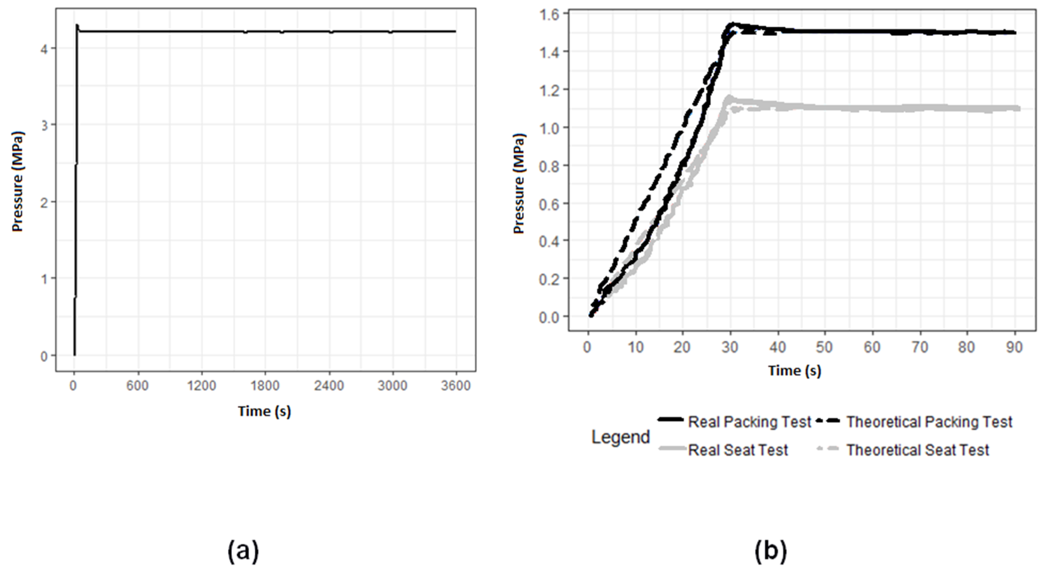
3.4. Shell Test on Final Assembly
4. Conclusions
- The MJF technology can encompass the market niche for both the functional prototype and the end parts in the fluid handling field. This technology is able to substitute conventional plastic transformation methods, such as plastic injection moulding.
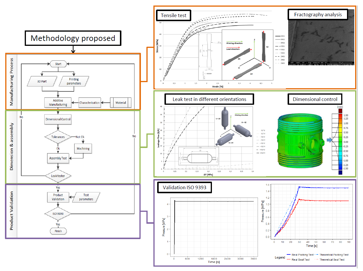
- This solution avoids sealing of the printed parts as a post-process for achieving the desired functionality in the fluid conduction industry. The coating and infiltration seals only allow maximum pressures of 0.45 MPa, while with MJF technology, 4.2 MPa of water pressure was achieved for one hour, due to the lack of porosity in its structure.
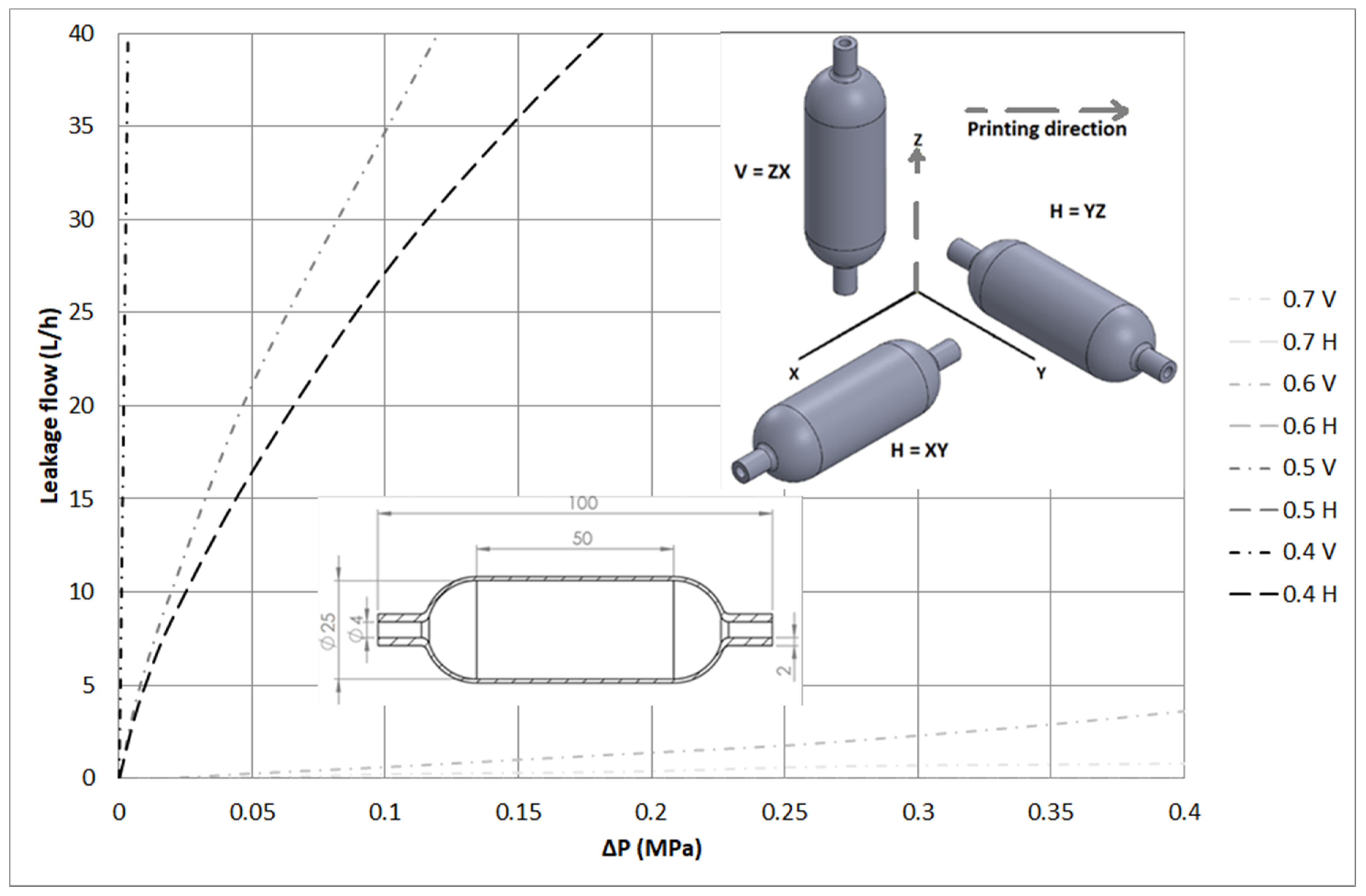
- Wall thickness and printing orientation are key variables which determine the watertightness of the samples. For the same wall thickness, vertical orientation requires higher number of layers to be printed, and therefore is more likely to have air gaps that lead to greater leak values. Test results show that for samples printed with the same orientation, a lower thickness leads to higher leak values.
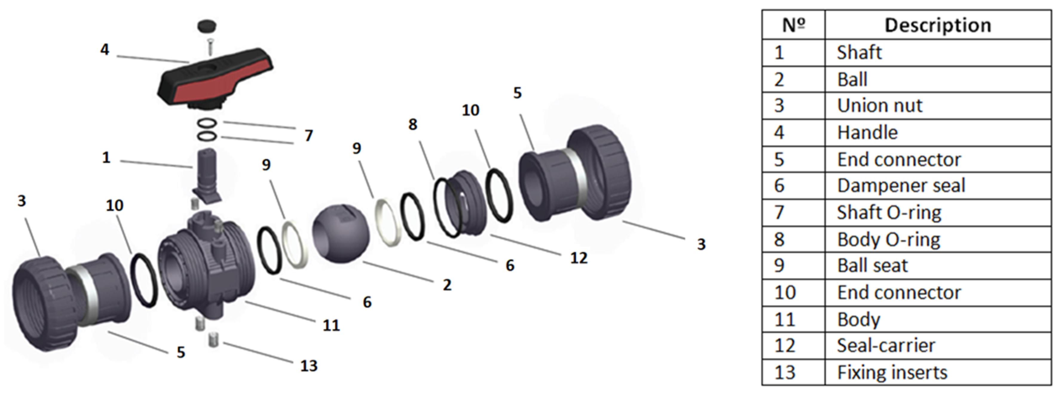
- Watertightness was validated through a real case: An industrial ball valve. The tests under the standard pressures of the shell and packaging/seat were satisfactory, showing no leaks and therefore comply with the quality control specified for PN10 ball valves made with thermoplastic material.
Author Contributions
Funding
Conflicts of Interest
References
- Gomez-Gras, G.; Jerez-Mesa, R.; Travieso-Rodriguez, J.A.; Lluma-Fuentes, J. Fatigue performance of fused filament fabrication PLA specimens. Mater. Des. 2018, 140, 278–285. [Google Scholar] [CrossRef] [Green Version]
- Ligon, S.C.; Liska, R.; Stampfl, J.; Gurr, M.; Mülhaupt, R. Polymers for 3D printing and customized additive aanufacturing. Chem. Rev. 2018, 117, 10212–10290. [Google Scholar] [CrossRef] [PubMed]
- Hopkinson, N.; Erasenthiran, P. High speed sintering—Early research into a new rapid manufacturing process. In Proceedings of the Solid Freeform Fabrication Symposium, Austin, TX, USA, 2–4 August 2004; pp. 312–320. [Google Scholar]
- Goodridge, R.; Ziegelmeier, S. Powder Bed Fusion of Polymers. In Laser Additive Manufacturing Materials, Design, Technologies, and Applications; Woodhead Publishing: Duxford, UK, 2017. [Google Scholar]
- Kim, G.D.; Oh, Y.T. A benchmark study on rapid prototyping processes and machines: Quantitative comparisons of mechanical properties, accuracy, roughness, speed, and material cost. Proc. Inst. Mech. Eng. Part. B J. Eng. Manuf. 2008, 222, 201–215. [Google Scholar] [CrossRef]
- Schmid, M.; Levy, G. Lasersintermaterialien—Aktueller stand und entwicklungspotential. In Proceedings of the Fachtagung Additive Fertigung, Lehrstuhl für Kunststofftechnik, Universität Erlangen, Erlangen, Germany, 27 October 2009; pp. 43–55. [Google Scholar]
- Cooper, K.G. Rapid Prototyping Technology; Marcel Dekker: New York, NY, USA, 2001. [Google Scholar]
- Gardan, J. Additive manufacturing technologies: State of the art and trends. Int. J. Prod. Res. 2016, 54, 3118–3132. [Google Scholar] [CrossRef]
- Domingo-Espin, M.; Borros, S.; Agullo, N.; Garcia-Granada, A.A.; Reyes, G. Influence of building parameters on the dynamic mechanical properties of polycarbonate fused deposition modeling parts. 3D Print. Addit. Manuf. 2014, 1, 70–77. [Google Scholar] [CrossRef]
- Domingo-Espin, M.; Puigoriol-Forcada, J.M.; Garcia-Granada, A.A.; Llumà, J.; Borros, S.; Reyes, G. Mechanical property characterization and simulation of fused deposition modeling Polycarbonate parts. Mater. Des. 2015, 83, 670–677. [Google Scholar] [CrossRef]
- Shaw, B.; Dirven, S. Investigation of Porosity and Mechanical Properties of Nylon SLS Structures. In Proceedings of the 23rd International Conference on Mechatronics and Machine Vision in Practice (M2VIP), Nanjing, China, 28–30 November 2016. [Google Scholar]
- Salazar-Martín, A.G.; Pérez, M.A.; García-Granada, A.A.; Reyes, G.; Puigoriol-Forcada, J.M. A study of creep in polycarbonate fused deposition modelling parts. Mater. Des. 2018, 141, 414–425. [Google Scholar] [CrossRef]
- Borkar, T.; Conteri, R.; Chen, X.; Ramanujan, R.V.; Banerjee, R. Laser additive processing of functionally-graded Fe–Si–B–Cu–Nb soft magnetic materials. Mater. Manuf. Process. 2017, 32, 1581–1587. [Google Scholar] [CrossRef]
- Choren, J.A.; Heinrich, S.M.; Silver-Thorn, M.B. Young’s modulus and volume porosity relationships for additive manufacturing applications. J. Mater. Sci. 2013, 48, 5103–5112. [Google Scholar] [CrossRef]
- Leigh, D.K. A comparison of polyamide 11 mechanical properties between laser sintering and traditional molding. In Proceedings of the 24th solid freeform fabrication symposium, The University of Texas at Austin, Austin, TX, USA, 6–8 August 2012. [Google Scholar]
- Bourell, D.; Kruth, J.P.; Leu, M.; Levy, G.; Rosen, D.; Beese, A.M.; Clare, A. Materials for additive manufacturing. CIRP Ann. 2017, 66, 659–681. [Google Scholar] [CrossRef]
- Mansour, S.; Gilbert, M.; Hague, R. A study of the impact of short-term ageing on the mechanical properties of a stereolithography resin. Mater. Sci. Eng. A 2007, 447, 277–284. [Google Scholar] [CrossRef]
- Puebla, K.; Arcaute, K.; Quintana, R.; Wicker, R.B. Effects of environmental conditions, aging, and build orientations on the mechanical properties of ASTM type I specimens manufactured via stereolithography. Rapid Prototyp. J. 2012, 18, 374–388. [Google Scholar] [CrossRef]
- Ottemer, X.; Colton, J.S. Effects of aging on epoxy-based rapid tooling materials. Rapid Prototyp. J. 2002, 8, 215–223. [Google Scholar] [CrossRef]
- Wu, Q.; Lu, J.; Liu, C.; Shi, X.; Ma, Q.; Tang, S.; Fan, H.; Ma, S. Obtaining uniform deposition with variable wire feeding direction during wire-feed additive manufacturing. Mater. Manuf. Process. 2017, 32, 1881–1886. [Google Scholar] [CrossRef]
- Pizzi, A.; Mittal, K.L. Handbook of Adhesive Technology; CRC Press: Boca Raton, FL, USA, 2017. [Google Scholar]
- Stratasys. Technical Application Guide: Comparision of Sealing Methods for Fdm Materials; Stratasys: Edina, MN, USA, 2015. [Google Scholar]
- Espalin, D.; Medina, F.; Arcaute, K.; Zinniel, B.; Hoppe, T.; Wicker, R. Effects of Vapor Smoothing on Abs Part Dimensions. In Proceedings of the Rapid Conference & Exposition, Schaumburg, Germany, 12–14 May 2009. [Google Scholar]
- Zhou, J.G.; Kokkengada, M.; He, Z.; Kim, Y.S.; Tseng, A. Low temperature polymer infiltration for rapid tooling. Mater. Des. 2004, 25, 145–154. [Google Scholar] [CrossRef]
- Mireles, J.; Adame, A.; Espalin, D.; Medina, F.; Winker, R.; Hoppe, T.; Zinniel, B.; Wicker, R. Analysis of Sealing Methods for Fdm-Fabricated Parts. In Proceedings of the 23th Solid Freeform Fabrication Symposium, The University of Texas at Austin, Austin, TX, USA, 6–8 August 2011. [Google Scholar]
- EN ISO 16135. Industrial Valves—Ball Valves of Thermoplastics Materials; ISO: Milano, Italy, 2007. [Google Scholar]
- Directive 97/23/EC. Approximation of the Laws of the Member States Concerning Pressure Equipment; European Parlament: Brussels, Belgium, 1997. [Google Scholar]
- ISO 9393-1. Thermoplastics Valves for Industrial Applications—Pressure Test Methods and Requirements—Part 1: General; ISO: Milano, Italy, 2004. [Google Scholar]
- ISO 228-1. Pipe Threads Where Pressure-Tight Joints Are not Made on The Threads—Part 1: Dimensions, Tolerances and Designation; ISO: Milano, Italy, 1994. [Google Scholar]
- ISO 9393-2. Thermoplastics Valves for Industrial Applications—Pressure Test Methods and Requirements—Part 2: Test Conditions and Basic Requirements; ISO: Milano, Italy, 2005. [Google Scholar]
- ASTM D638. Standard Test Method for Tensile Properties of Plastics; ASTM: West Conshohocken, PA, USA, 1997. [Google Scholar]
- GOST normative 10589-63. Moulding Polyamide 610; Gost: Moscow, Russia, 2004. [Google Scholar]
- GOST normative 9639-61. Sheet Vinyl Plasti; Gost: Moscow, Russia, 2000. [Google Scholar]
- Pisarenko, G.S.; Yakovlev, A.P.; Matveev, V.V. Manual de Resistencia de Materiales; Spanish Translation from Handbook on Strength of Materials; Naukova Dumka: Kiev, Ukraine, 1975. (In Russian) [Google Scholar]
- Krahmer, D.M.; Polvorosa, R.; López de Lacalle, L.; Alonso-Pinillos, U.; Abate, G.; Riu, F. Alternatives for specimen manufacturing in tensile testing of steel plates. Exp. Tech. 2016, 40, 1555–1565. [Google Scholar] [CrossRef]


| Property | Value | Normative |
|---|---|---|
| Powder melting point (DSC) | 187 °C | ASTM D3418 |
| Particle size | 60 µm | ASTM D3451 |
| Bulk density of powder | 0.425 g/cm3 | ASTM D1895 |
| Density of parts | 1.01 g/cm3 | ASTM D792. |
| Material | Minimum Test Time | Pressure Test (Ptest)1 | Design Stress (σt)2 | Assembly Stress (σs)3 | Temperature | Inner Fluid | Outer Fluid |
|---|---|---|---|---|---|---|---|
| PVC-U | 1 h | 4.2 MPa | 42 MPa | 10 MPa | 20 ± 2 °C | Water | Water or Air |
| Test | Test Minimum Time | Test Pressure (Ptest) | Temperature | Inner Fluid | Outer Fluid |
|---|---|---|---|---|---|
| Seat test (close valve) | DN ≤ 200 = 15 s | 1.1 MPa | 20 ± 2 °C | Water | Air |
| Packing test (open valve) | DN > 50 = 30 s | 1.5 MPa | 20 ± 2 °C | Water | Air |
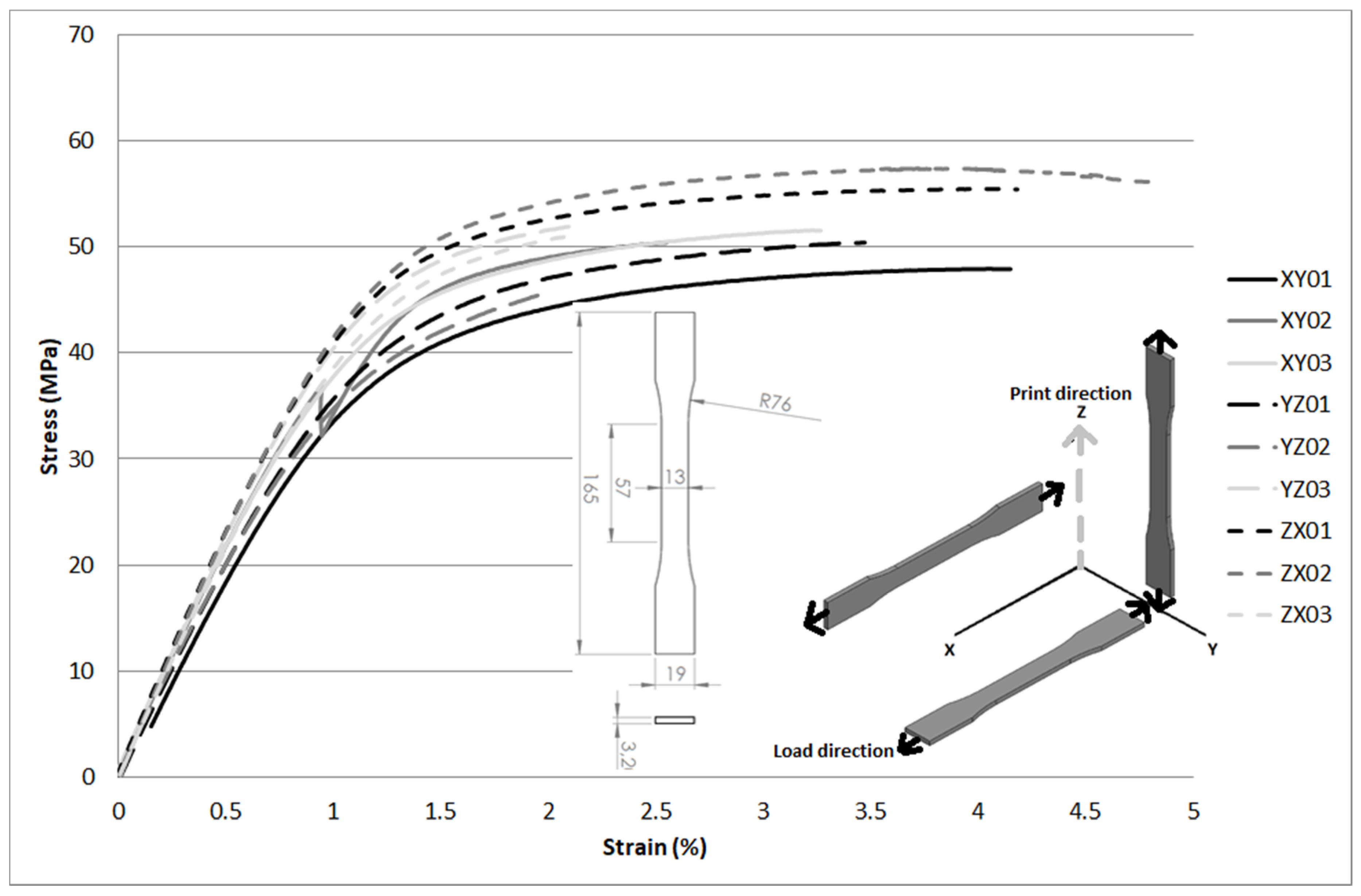
| Specimen | E (GPa) | σy (MPa) | σm (MPa) | εr (%) |
|---|---|---|---|---|
| XY01 | 3.525 | 33.5 | 47.9 | 4.1 |
| XY02 | 4.202 | 35.2 | 50.3 | 2.5 |
| XY03 | 4.087 | 37.7 | 51.6 | 3.3 |
| YZ01 | 3.817 | 35.5 | 50.3 | 2.5 |
| YZ02 | 3.767 | 34.6 | 45.6 | 2.0 |
| YZ03 | 4.321 | 40.4 | 52.1 | 2.2 |
| ZX01 | 4.391 | 41.5 | 55.4 | 4.2 |
| ZX02 | 4.409 | 41.4 | 57.4 | 4.8 |
| ZX03 | 4.106 | 40.1 | 50.9 | 2.1 |
| PA (GOST 10589-63) [32] | 1.167 | - | 49.0–58.8 | 100 |
| PVC-U (GOST 9639–61) [33] | 2.942–3.923 | – | 39.2–58.8 | 10–100 |
| Thickness (mm) | Printing Orientation (H = Horizontal and V = Hertical) | Pressure to Leak 3L/h (MPa) |
|---|---|---|
| 0.7 | V | >0.400 |
| 0.7 | H | >0.400 |
| 0.6 | V | 0.357 |
| 0.6 | H | >0.400 |
| 0.5 | V | 0.044 |
| 0.5 | H | >0.400 |
| 0.4 | V | 0.003 |
| 0.4 | H | 0.052 |
© 2018 by the authors. Licensee MDPI, Basel, Switzerland. This article is an open access article distributed under the terms and conditions of the Creative Commons Attribution (CC BY) license (http://creativecommons.org/licenses/by/4.0/).
Share and Cite
Morales-Planas, S.; Minguella-Canela, J.; Lluma-Fuentes, J.; Travieso-Rodriguez, J.A.; García-Granada, A.-A. Multi Jet Fusion PA12 Manufacturing Parameters for Watertightness, Strength and Tolerances. Materials 2018, 11, 1472. https://doi.org/10.3390/ma11081472
Morales-Planas S, Minguella-Canela J, Lluma-Fuentes J, Travieso-Rodriguez JA, García-Granada A-A. Multi Jet Fusion PA12 Manufacturing Parameters for Watertightness, Strength and Tolerances. Materials. 2018; 11(8):1472. https://doi.org/10.3390/ma11081472
Chicago/Turabian StyleMorales-Planas, Sergio, Joaquim Minguella-Canela, Jordi Lluma-Fuentes, Jose Antonio Travieso-Rodriguez, and Andrés-Amador García-Granada. 2018. "Multi Jet Fusion PA12 Manufacturing Parameters for Watertightness, Strength and Tolerances" Materials 11, no. 8: 1472. https://doi.org/10.3390/ma11081472