Recent Developments in Carbon Nanotube Membranes for Water Purification and Gas Separation

 and
and 
Abstract
:
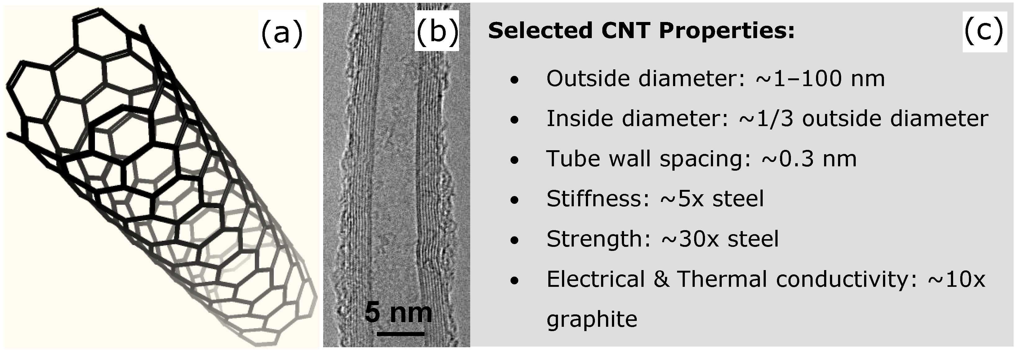
1. Introduction
2. Bucky-Paper Membranes
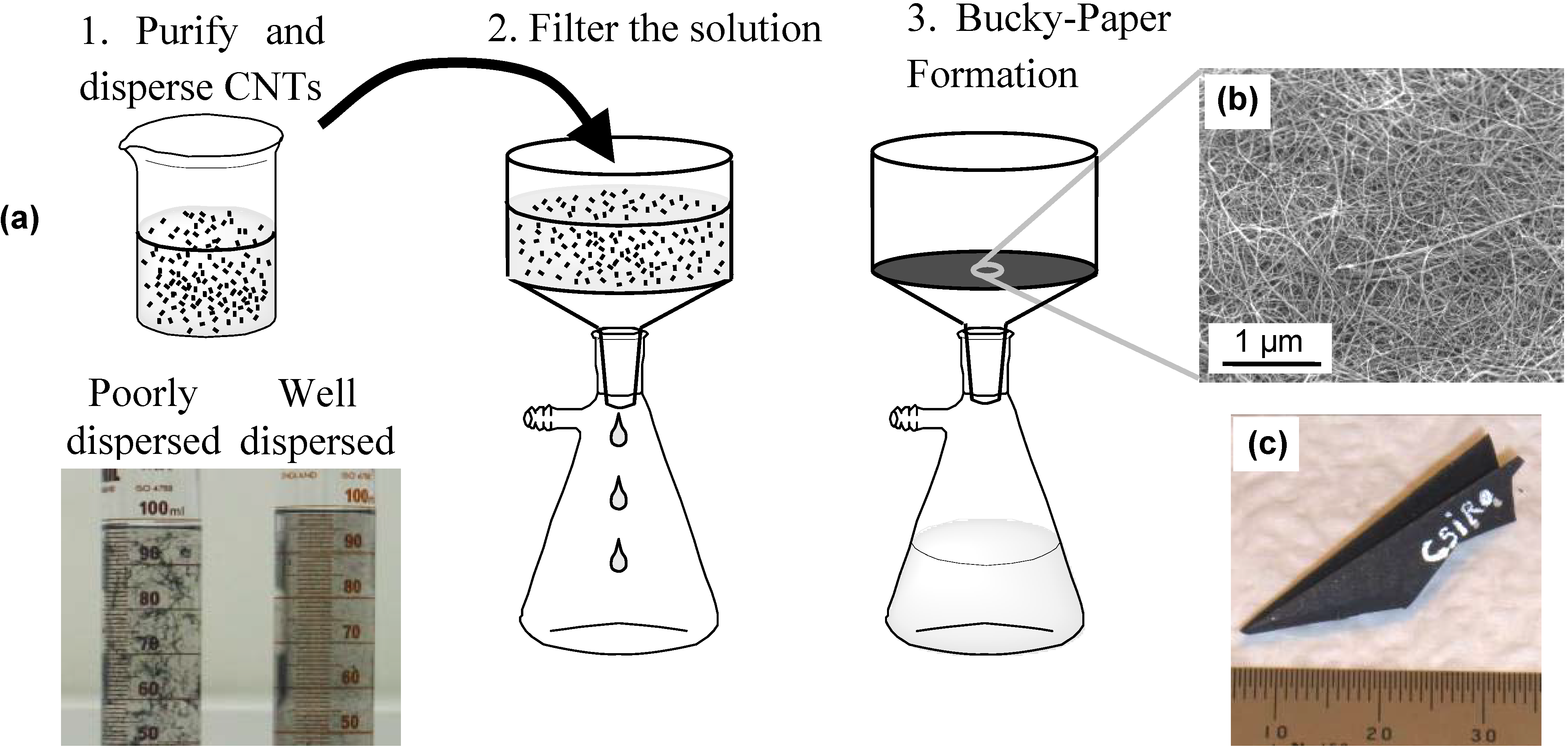
2.1. Bucky-Paper Processing

- (i)
- (ii)
- (iii)
- mechanical treatments such as ultrasonication and shear mixing.
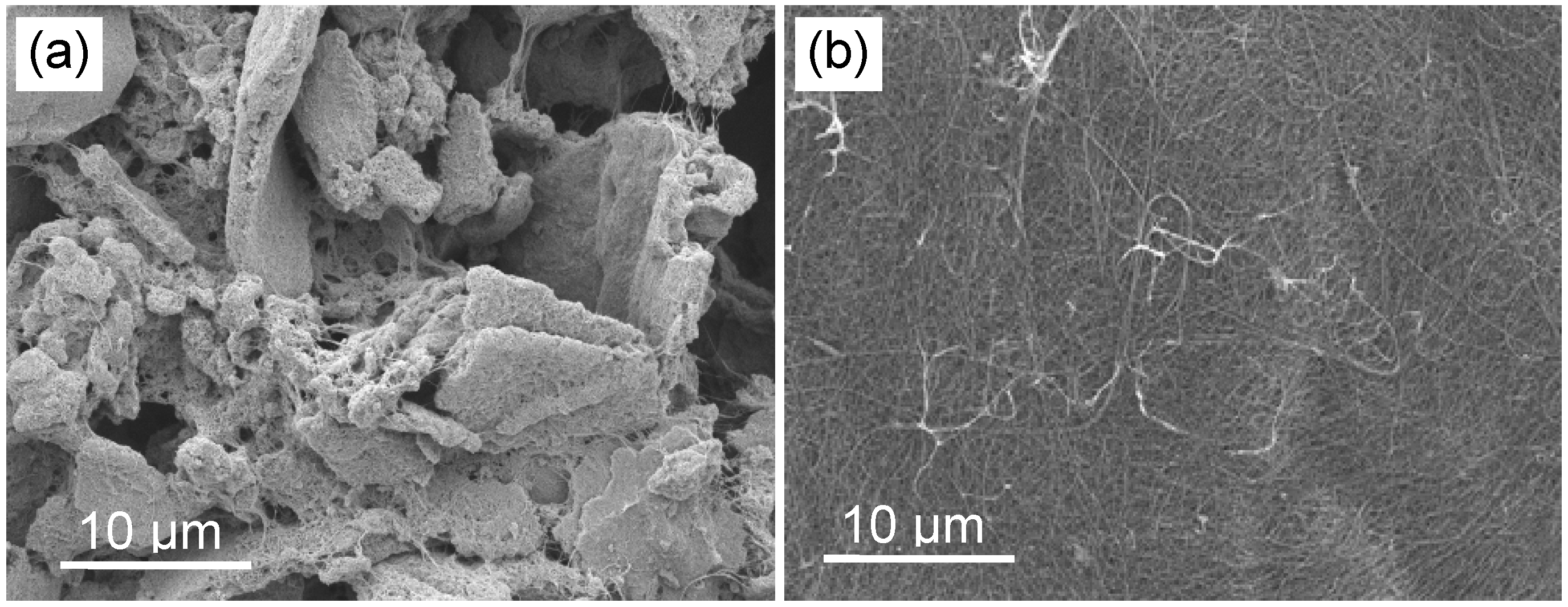
2.2. Bucky-Paper Structure and Properties


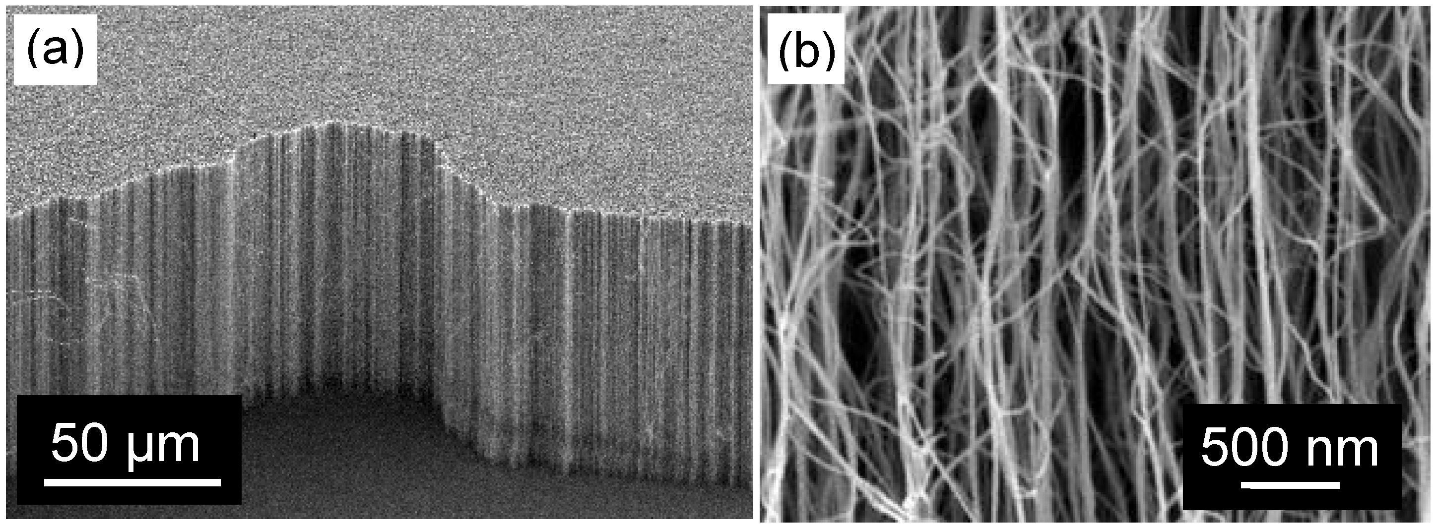
| CNT Type | Coarse | Fine |
|---|---|---|
| Inner diameter (nm) | 10 ± 5.5 | 4.5 ± 1 |
| Outer diameter (nm) | 37 ± 16 | 9 ± 1.5 |
| # walls | 37 ± 21 | 6 ± 2 |
| Length (µm) | 200–400 | 200–400 |
| Impurity content | <10 wt % | <5 wt % |


2.3. Bucky-Papers for Water Purification and Filtration
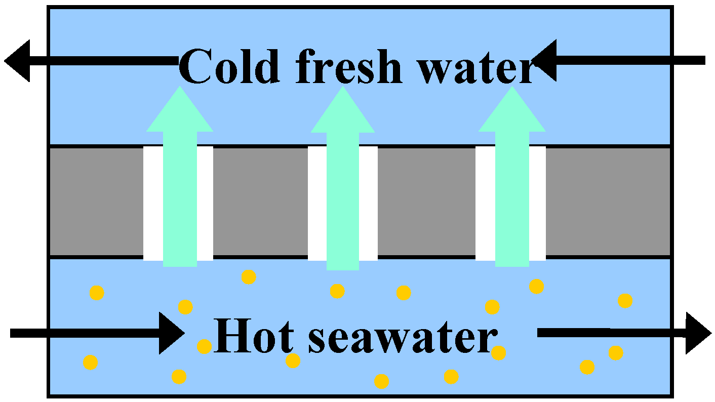
2.3.1. Membrane Distillation

2.3.2. Other Applications
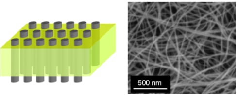
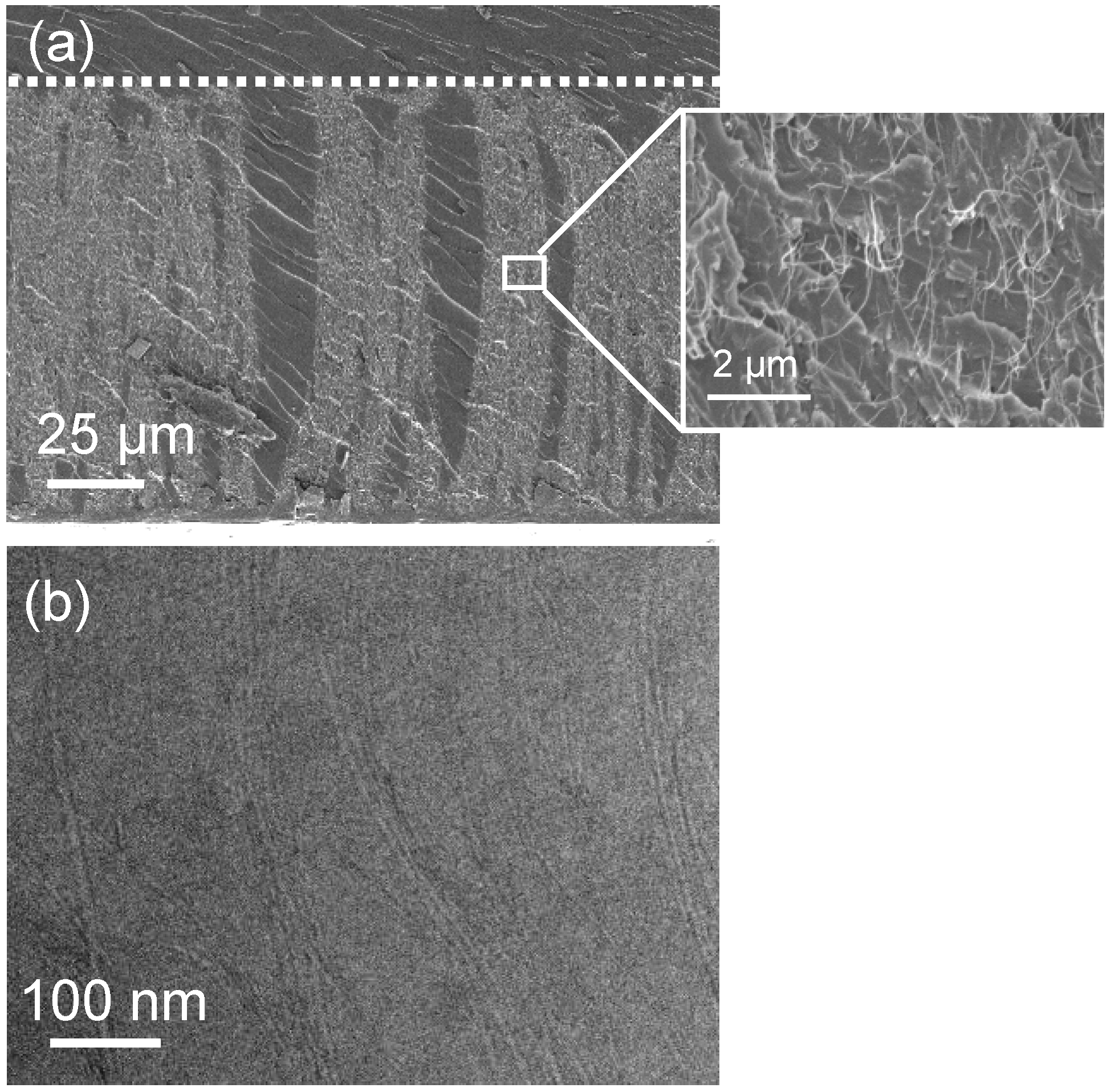
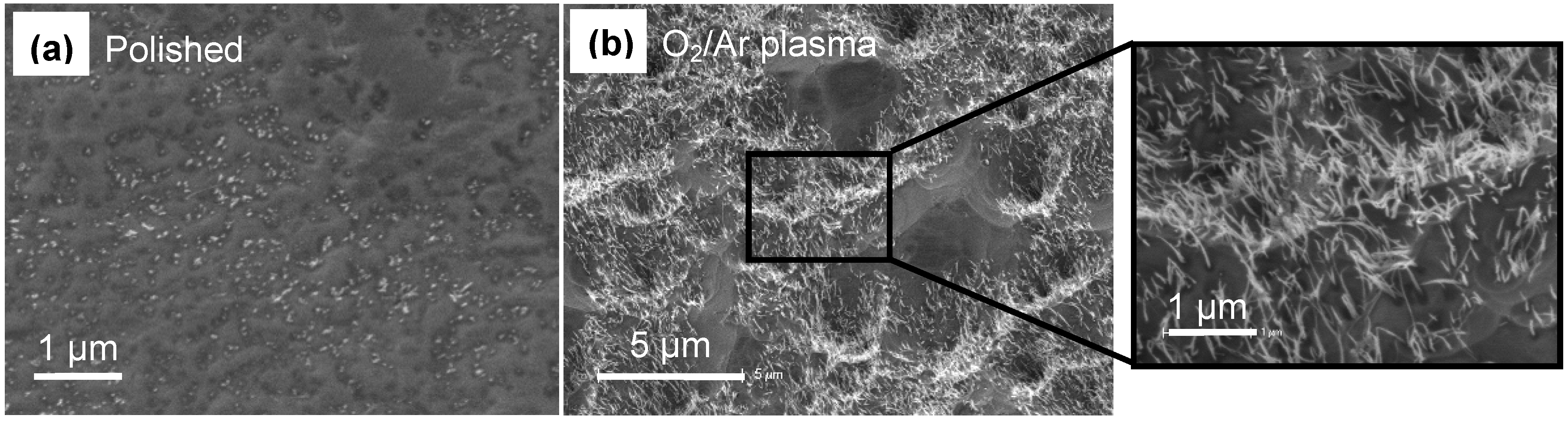
3. Isoporous Carbon Nanotube Membranes
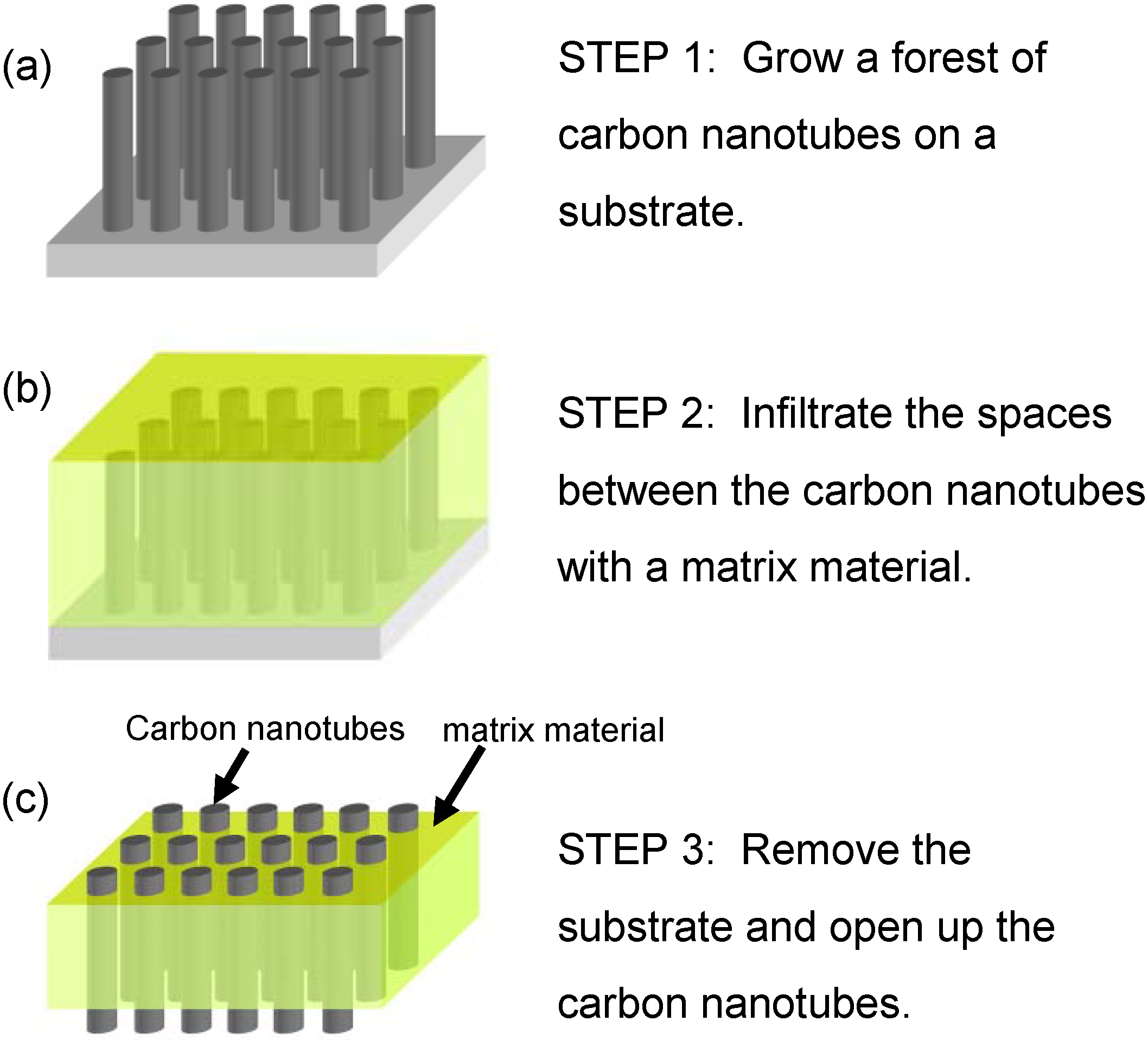
3.1. Membrane Construction

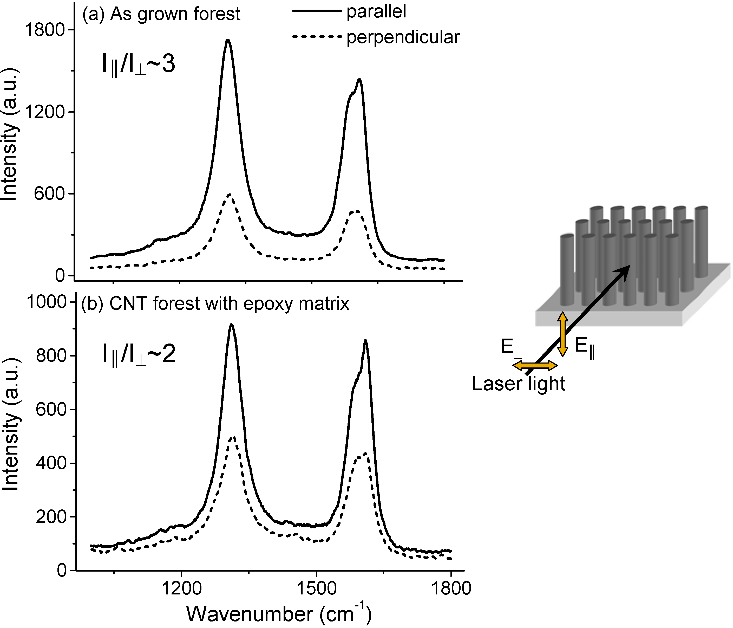
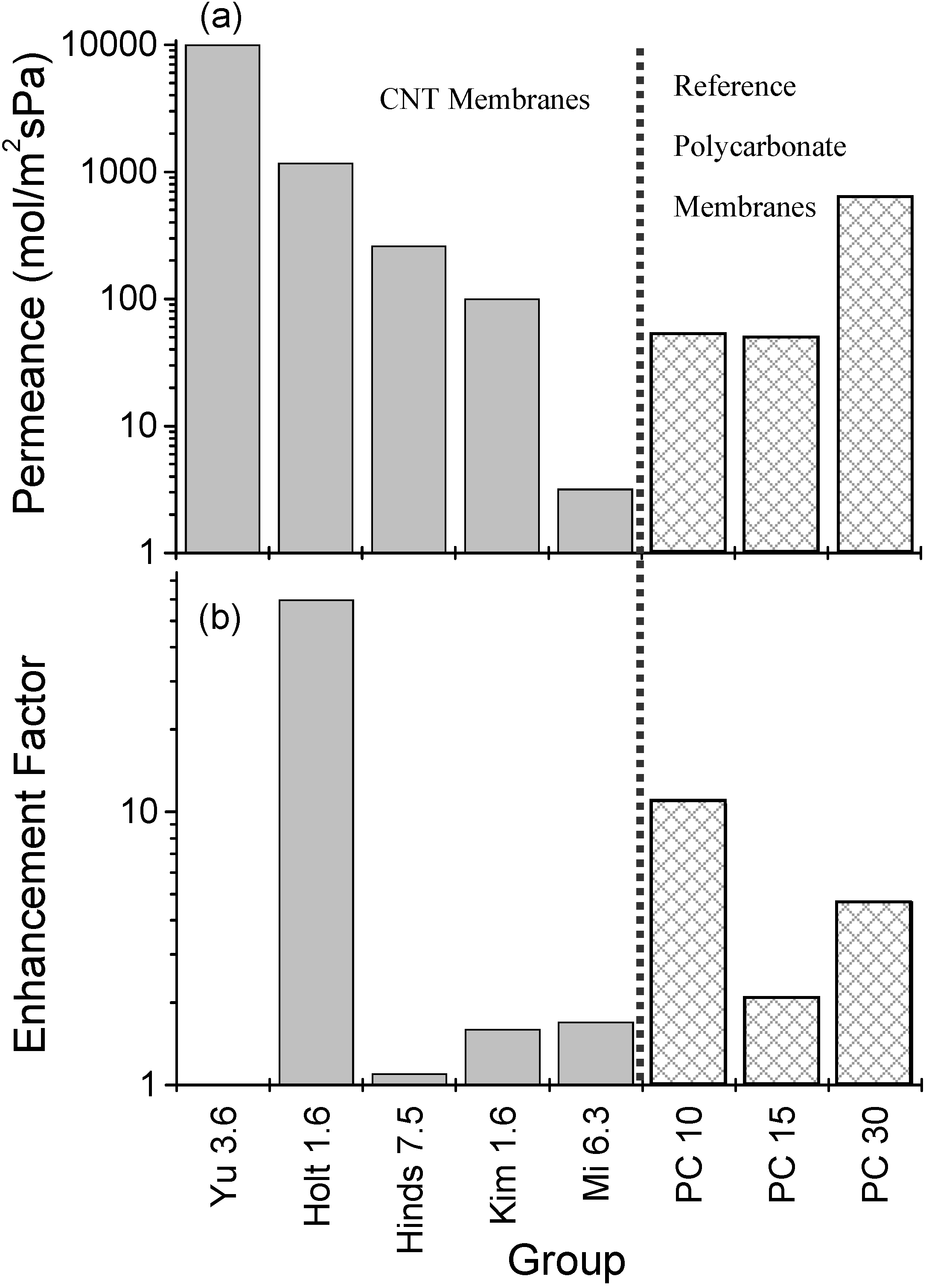
3.2. Gas Permeance
4. Conclusions
Acknowledgements
Supplementary Materials
References and Notes
- Holt, J.K.; Park, H.G.; Wang, Y.; Staderman, M.; Artyukhin, A.B.; Grigoropoulos, C.P.; Noy, A.; Bakajin, O. Fast Mass Transport Through Sub-2-Nanometer Carbon Nanotubes. Science 2006, 312, 1034–1037. [Google Scholar] [CrossRef] [PubMed]
- Hinds, B.J.; Chopra, N.; Rantell, T.; Andrews, R.; Gavalas, V.; Bachas, L.G. Aligned Multiwalled Carbon Nanotube Membranes. Science 2004, 303, 62–65. [Google Scholar] [CrossRef] [PubMed]
- Majumder, M.; Chopra, N.; Andrews, R.; Hinds, B.J. Enhanced Flow in Carbon Nanotubes. Nature 2005, 438, 44. [Google Scholar] [CrossRef] [PubMed]
- Srivastava, A.; Srivastava, O.N.; Talapatra, S.; Vajtai, R.; Ajayan, P.M. Carbon Nanotube Filters. Nature 2004, 3, 610–614. [Google Scholar] [CrossRef]
- Li, X.; Zhu, G.; Dordick, J.S.; Ajayan, P.M. Compression-Modulated Tunable-Pore Carbon-Nanotube Membrane Filters. Small 2007, 3, 595–599. [Google Scholar] [CrossRef] [PubMed]
- Kim, S.; Jinschek, J.R.; Chen, H.; Sholl, D.S.; Marand, E. Scalable Fabrication of Carbon Nanotube/Polymer Nanocomposite Membranes for High Flux Gas Transport. Nano Lett. 2007, 7, 2806–2811. [Google Scholar] [CrossRef] [PubMed]
- Kim, S.; Pechar, T.W.; Marand, E. Poly(imide siloxane) and Carbon Nanotube Mixed Matrix Membranes for Gas Separation. Desalination 2006, 192, 330–339. [Google Scholar] [CrossRef]
- Peng, F.; Pan, F.; Sun, H.; Lu, L.; Jiang, Z. Novel Nanocomposite Pervaporation Membranes composed of Poly(vinyl alcohol) and Chitosan-Wrapped Carbon Nanotubes. J. Membr. Sci. 2007, 300, 13–19. [Google Scholar] [CrossRef]
- Peng, F.; Hu, C.; Jiang, Z. Novel Poly(vinyl alcohol)/Carbon Nanotube Hybrid Membranes for Pervaporation Separation of Benzene/Cyclohexane Mixtures. J. Membr. Sci. 2007, 297, 236–242. [Google Scholar] [CrossRef]
- Mi, W.; Lin, Y. S.; Li, Y. Vertically Aligned Carbon Nanotube Membranes on Macroporous Alumina Supports. J. Membr. Sci. 2007, 304, 1–7. [Google Scholar] [CrossRef]
- Whitby, M.; Cagnon, L.; Thanou, M.; Quirke, N. Enhanced Fluid Flow through Nanoscale Carbon Pipes. Nano Lett. 2008, 8, 2632–2637. [Google Scholar] [CrossRef] [PubMed]
- Dumée, L.F.; Sears, K.; Schütz, J.; Finn, N.; Huynh, C.; Hawkins, S.; Duke, M.; Gray, S. Characterisation and Evaluation of Carbon Nanotube Bucky-paper Membranes for Direct Contact Membrane Distillation. J. Membr. Sci. 2009. Submitted. [Google Scholar]
- Iijima, S. Helical Microtubules of Graphitic Carbon. Nature 1991, 354, 56–58. [Google Scholar] [CrossRef]
- O'Connell, M.J. Carbon Nanotubes: Properties and Applications; Taylor & Francis Group: Boca Raton, FL, USA, 2006. [Google Scholar]
- Dresselhaus, M.S.; Dresselhaus, G.; Avouris, Ph. Carbon Nanotubes: Synthesis, Structure, Properties, and Applications; Springer: Berlin, Germany, 2001. [Google Scholar]
- Baughman, R.H.; Zakhidov, A.A.; De Heer, W.A. Carbon Nanotubes-the Route toward Applications. Science 2002, 297, 787–792. [Google Scholar] [CrossRef] [PubMed]
- Zhang, X.; Sreekumar, T.V.; Liu, T.; Kumar, S. Properties and Structure of Nitric Acid Oxidized Single Walled Carbon Nanotube Films. J. Phys. Chem. B 2004, 108, 16435–16440. [Google Scholar] [CrossRef]
- Xu, G.; Zhang, Q.; Zhou, W.; Huang, J.; Wei, F. The Feasibility of Producing MWCNT Paper and Strong MWCNT Film from VACNT Array. Appl. Phys. A: Mater. Sci. Process. 2008, 92, 531–539. [Google Scholar] [CrossRef]
- Bandow, S.; Rao, A.M.; Williams, K.A.; Thess, A.; Smalley, R.E.; Eklund, P.C. Purification of Single-Wall Carbon Nanotubes by Microfiltration. J. Phys. Chem. B 1997, 101, 8839–8842. [Google Scholar] [CrossRef]
- Baughman, R.H.; Cui, C.; Zakhidov, A.A.; Iqbal, Z.; Barisci, J.N.; Spinks, G.M.; Wallace, G.G.; Mazzoldi, A.; Rossi, D.D.; Rinzler, A.G.; Jaschinski, O.; Roth, S.; Kertesz, M. Carbon Nanotube Actuators. Science 1999, 284, 1340–1344. [Google Scholar] [CrossRef]
- Kim, B.Y.A.; Muramatsu, H.; Hayashi, T.; Endo, M.; Terrones, M.; Dresselhaus, M.S. Fabrication of High Purity, Double-Walled Carbon Nanotube Buckypaper. Chem. Vap. Deposition 2006, 12, 327–330. [Google Scholar] [CrossRef]
- Park, J.G.; Li, S.; Fan, X.; Zhang, C.; Wang, B. The High Current-Carrying Capacity of Various Carbon Nanotube-Based Buckypapers. Nanotechnology 2008, 19, 185710:1–185710:7. [Google Scholar]
- Endo, M.; Muramatsu, H.; Hayashi, T.; Kim, Y.A.; Terrones, M.; Dresselhaus, M.S. 'Buckypaper' from Coaxial Nanotubes. Nature 2005, 433, 476. [Google Scholar] [CrossRef] [PubMed]
- Park, T.J.; Banerjee, S.; Hemraj-Benny, T.; Wong, S.S. Purification Strategies and Purity Visualization for Single-Walled Carbon Nanotubes. J. Mater. Chem. 2006, 16, 141–154. [Google Scholar] [CrossRef]
- Suppiger, D.; Busato, S.; Ermanni, P. Characterization of Single-Walled Carbon Nanotube Mats and their Performance as Electromechanical Actuators. Carbon 2008, 46, 1085–1090. [Google Scholar] [CrossRef]
- Vohrer, U.; Kolaric, I.; Haque, M.H.; Roth, S.; Detlaff-Weglikowska, U. Carbon Nanotube Sheets for the Use as Artificial Muscles. Carbon 2004, 42, 1159–1164. [Google Scholar] [CrossRef]
- Rouse, J.H. Polymer-Assisted Dispersion of Single-Walled Carbon Nanotubes in Alcohols and Applicability toward Carbon Nanotube/Sol-Gel Composite Formation. Langmuir 2005, 21, 1055–1061. [Google Scholar] [CrossRef] [PubMed]
- Bandow, S.; Asaka, S.; Zhao, X.; Ando, Y. Purification and Magnetic Properties of Carbon Nanotubes. Appl. Phys. A: Mater. Sci. Process. 1998, 67, 23–27. [Google Scholar] [CrossRef]
- Cinke, M.; Li, J.; Chen, B.; Cassell, A.; Delzeit, L.; Han, J.; Meyyappan, M. Pore Structure of Raw and Purified HiPco Single-Walled Carbon Nanotubes. Chem. Phys. Lett. 2002, 365, 69–74. [Google Scholar] [CrossRef]
- Dillon, A.C.; Gennett, T.; Jones, K.M.; Alleman, J.L.; Parilla, P.A.; Heben, M.J. A Simple and Complete Purification of Single-Walled Carbon Nanotube Materials. Adv. Mater. 1999, 11, 1354–1358. [Google Scholar] [CrossRef]
- Xu, Y.Q.; Peng, H.; Hauge, R.H.; Smalley, R.E. Controlled Multistep Purification of Single-Walled Carbon Nanotubes. Nano Lett. 2005, 5, 163–168. [Google Scholar] [CrossRef] [PubMed]
- Ziegler, K.J.; Gu, Z.; Peng, H.; Flor, E.L.; Hauge, R.H.; Smalley, R.E. Controlled Oxidative Cutting of Single-Walled Carbon Nanotubes. J. Am. Chem. Soc. 2005, 127, 1541–1547. [Google Scholar] [CrossRef] [PubMed]
- Hu, H.; Zhao, B.; Itkis, M.E.; Haddon, R.C. Nitric Acid Purification of Single-Walled Carbon Nanotubes. J. Phys. Chem. B 2003, 107, 13838–13842. [Google Scholar] [CrossRef]
- Vaisman, L.; Wagner, H.D.; Marom, G. The Role of Surfactants in Dispersion of Carbon Nanotubes. Adv. Colloid Interface Sci. 2006, 128–130, 37–46. [Google Scholar] [CrossRef] [PubMed]
- Sun, Z.; Nicolosi, V.; Rickard, D.; Bergin, S.D.; Aherne, D.; Coleman, J.N. Quantitative Evaluation of Surfactant-Stabilised Single-Walled Carbon Nanotubes:Dispersion Quality and Its Correlation with Zeta Potential. J. Phys. Chem. C 2008, 112, 10692–10699. [Google Scholar] [CrossRef]
- Shaffer, M.S.P.; Fan, X.; Windle, A.H. Dispersion and Packing of Carbon Nanotubes. Carbon 1998, 36, 1603–1612. [Google Scholar] [CrossRef]
- Lin, T.; Bajapi, V.; Ji, T.; Dai, L. Chemistry of Carbon Nanotubes. Aust. J. Chem. 2003, 56, 635–651. [Google Scholar] [CrossRef]
- Yu, J.; Grossiord, N.; Koning, C.E.; Loos, J. Controlling the Dispersion of Multi-Wall Carbon Nanotubes in Aqueous Surfactant Solution. Carbon 2007, 45, 618–623. [Google Scholar] [CrossRef]
- Wang, Y.; Gao, L.; Sun, J.; Liu, Y.; Zheng, S.; Kajiura, H.; Li, Y.; Noda, K. An Integrated Route for Purification, Cutting and Dispersion of Single-Walled Carbon Nanotubes. Chem. Phys. Lett. 2006, 432, 205–208. [Google Scholar] [CrossRef]
- Priya, B.R.; Byrne, H.J. Investigation of Sodium Dodecyl Benzene Sulfonate Assisted Dispersion and Debundling of Single-Walled Carbon Nanotubes. J. Phys. Chem. B 2008, 112, 332–337. [Google Scholar] [CrossRef]
- Nish, A.; Hwang, J.J.; Doig, J.; Nicholas, R.J. Highly Selective Dispersion of Single-Walled Carbon Nanotubes Using Aromatic Polymers. Nature 2007, 2, 640–646. [Google Scholar]
- Zheng, M.; Jagota, A.; Semke, E.D.; Diner, B.A.; Mclean, R.S.; Lustig, S.R.; Richardson, R.E.; Tassis, N.G. DNA-Assisted Dispersion and Separation of Carbon Nanotubes. Nature 2003, 2, 338–342. [Google Scholar] [CrossRef]
- Hou, P.X.; Liu, C.; Cheng, H.-M. Purification of Carbon Nanotubes. Carbon 2008, 46, 2003–2025. [Google Scholar] [CrossRef]
- Hirsch, A.; Vostrowsky, O. Functionalization of Carbon Nanotubes. Top. Curr. Chem. 2005, 245, 193–237. [Google Scholar]
- Dumée, L.; Sears, K.; Schütz, J.; Finn, N.; Duke, M.; Gray., S. Design and Characterisation of Carbon Nanotube Bucky-Paper Membranes for Membrane Distillation. Desalin. Water Treat. 2009. Submitted. [Google Scholar]
- Hernández, A.; Calvo, J.I.; Prádanos, P.; Tejerina, F. Pore Size Distributions in Microporous Membranes. A Critical Analysis of the Bubble Point Extended Method. J. Membr. Sci. 1996, 112, 1–12. [Google Scholar] [CrossRef]
- Smajda, R.; Kukovecz, Á.; Kónya, Z.; Kiricsi, I. Structure and Gas Permeability of Multi-Wall Carbon Nanotube Buckypapers. Carbon 2007, 45, 1176–1184. [Google Scholar] [CrossRef]
- Kukovecz, Á.; Smajda, R.; Kónya, Z.; Kiricsi, I. Controlling the Pore Diameter Distribution of Multi-Wall Carbon Nanotube Buckypapers. Carbon 2007, 45, 1696–1716. [Google Scholar] [CrossRef]
- Whitby, R.L.D.; Fukuda, T.; Maekawa, T.; James, S.L.; Mikhalovsky, S.V. Geometric Control and Tuneable Pore Size Distribution of Buckypaper and Buckydiscs. Carbon 2008, 46, 949–956. [Google Scholar] [CrossRef]
- Das, R.K.; Liu, B.; Reynolds, J.R.; Rinzler, A.G. Engineered Macroporosity in Single-Wall Carbon Nanotube Films. Nano Lett. 2009, 9, 677–683. [Google Scholar] [CrossRef] [PubMed]
- Casavant, M.J.; Walters, D.A.; Scmidt, J.J.; Smalley, R.E. Neat Macroscopic Membranes of Aligned Carbon Nanotubes. J. Appl. Phys. 2003, 93, 2153–2156. [Google Scholar] [CrossRef]
- Wang, D.; Song, P.; Liu, C.; Wu, W.; Fan, S. Highly Oriented Carbon Nanotube Papers made of Aligned Carbon Nanotubes. Nanotechnology 2008, 19, 075609:1–075609:7. [Google Scholar]
- Gonnet, P.; Liang, Z.; Choi, E.S.; Kadambala, R.S.; Zhang, C.; Brooks, J.S.; Wang, B.; Kramer, L. Thermal Conductivity of Magnetically Aligned Carbon Nanotube Buckypapers and Nanocomposites. Curr. Appl. Phys. 2006, 6, 119–122. [Google Scholar] [CrossRef]
- Hone, J.; Liaguno, M.C.; Nemes, N.M.; Johnson, A.T.; Fischer, J.E.; Walters, D.A.; Casavant, M.J.; Schmidt, J.; Smalley, R.E. Electrical and Thermal Transport Properties of Magnetically Aligned Single Wall Carbon Nanotube Films. Appl. Phys. Lett. 2000, 77, 666–668. [Google Scholar] [CrossRef]
- Lawson, K.W.; Lloyd, D.R. Membrane Distillation. J. Membr. Sci. 1997, 124, 1–25. [Google Scholar] [CrossRef]
- Hoang, M.; Bolto, B.; Tran, T. Desalination by Capacitive Deionisation. Water 2009, February, 63–66. [Google Scholar]
- Pan, L.; Wang, X.; Zhang, Y.; Chen, Y.; Sun, Z. Electrosorption of Anions with Carbon Nanotube and Nanofibre Composite Film Electrodes. Desalination 2009, 244, 193–143. [Google Scholar] [CrossRef]
- Wang, X.; Li, M.; Chen, R.; Huang, S.; Pan, L.; Sun, Z. Electrosorption of Ions from Aqueous Solutions with Carbon Nanotubes and Nanofibers Composite Film Electrodes. Appl. Phys. Lett. 2006, 89, 053127. [Google Scholar] [CrossRef]
- Li, H.; Gao, Y.; Pan, L.; Zhang, Y.; Chen, Y.; Sun, Z. Electrosorptive Desalination by Carbon Nanotubes and Nanofibers Electrodes and Ion-Exchange Membranes. Water Res. 2008, 42, 4923–4928. [Google Scholar] [CrossRef] [PubMed]
- Dai, K.; Shi, L.; Zhang, D.; Fang, J. NaCl Adsorption in Multi-Walled Carbon Nanotube/Active Carbon Combination Electrode. Chem. Eng. Sci. 2006, 61, 428–433. [Google Scholar] [CrossRef]
- Viswanathan, G.; Kane, D.B.; Lipowicz, P.J. High Efficiency Fine Particulate Filtration Using Carbon Nanotube Coatings. Adv. Mater. 2004, 16, 2045–2049. [Google Scholar] [CrossRef]
- Kang, S.; Pinault, M.; Pfefferle, L.D.; Elimelech, M. Single-Walled Carbon Nanotubes Exhibit Strong Antimicrobial Activity. Langmuir 2007, 23, 8670–8673. [Google Scholar] [CrossRef] [PubMed]
- Brady-Esétvez, A.S.; Kang, S.; Elimelech, M.A. Single-Walled-Carbon-Nanotube Filter for Removal of Viral and Bacterial Pathogens. Small 2008, 4, 481–484. [Google Scholar] [CrossRef] [PubMed]
- Edwards, S.L.; Church, J.S.; Werkmeister, J.A.; Ramshaw, J.A.M. Tubular Micro-scale Multiwalled Carbon Nanotube-based Scaffolds for Tissue Engineering. Biomaterials 2009, 30, 1725–1731. [Google Scholar] [CrossRef] [PubMed]
- Voher, U.; Zschoerper, N.P.; Koehne, Y.; Langowski, S.; Oehr, C. Plasma Modification of Carbon Nanotubes and Bucky Papers. Plasma Process. Polym. 2007, 4, S871–S877. [Google Scholar] [CrossRef]
- Correa-Duarte, M.A.; Wagner, N.; Rojas-Chapana, J.; Morsczeck, C.; Thie, M.; Giersig, M. Fabrication and Biocompatibility of Carbon Nanotube-based 3D Networks as Scaffolds for Cell Seeding and Growth. Nano Lett. 2004, 4, 2233–2236. [Google Scholar] [CrossRef]
- Galvan-Garcia, P.; Keefer, E.K.; Yang, F.; Zhang, M.; Fang, S.; Zakhidov, A.A.; Baughman, R.H.; Romero, M. Robust Cell Migration and Neuronal Growth on Pristine Carbon Nanotube Sheets and Yarns. J. Biomater. Sci., Polym. Ed. 2007, 18, 1245–1261. [Google Scholar] [CrossRef]
- Hummer, G.; Rasalah, J.C.; Noworyta, J.P. Water Conduction through the Hydrophobic Channel of a Carbon Nanotube. Nature 2001, 414, 188–190. [Google Scholar] [CrossRef] [PubMed]
- Skoulidas, A.; Ackerman, D.M.; Johnson, K.; Sholl, D.S. Rapid Transport of Gases in Carbon Nanotubes. Phys. Rev. Lett. 2002, 89, 185901:1–185901:4. [Google Scholar] [CrossRef]
- Chen, H.; Johnson, J.K.; Sholl, D.S. Transport Diffusion of Gases is Rapid in Flexible Carbon Nanotubes. J. Phys. Chem. B 2006, 110, 1971–1975. [Google Scholar] [CrossRef] [PubMed]
- Waghe, A.; Rasaiah, J.C.; Hummer, G. Filling and Emptying Kinetics of Carbon Nanotubes in Water. J. Chem. Phys. 2002, 117, 10789–10795. [Google Scholar] [CrossRef]
- Noy, A.; Park, H.G.; Fornasiero, F.; Holt, J.K.; Grigoropoulos, C.P.; Bakajin, O. Nanofluidics in Carbon Nanotubes. Nanotoday 2007, 2, 22–29. [Google Scholar] [CrossRef]
- Corry, B. Designing Carbon Nanotube Membranes for Efficient Water Desalination. J. Phys. Chem. B 2008, 112, 1427–1434. [Google Scholar] [CrossRef] [PubMed]
- Thomas, J.A.; McGaughey, J.H. Reassessing Fast Water Transport through Carbon Nanotubes. Nano Lett. 2008, 8, 2788–2793. [Google Scholar] [CrossRef] [PubMed]
- Zheng, J.; Lennon, E.M.; Tsao, H. K.; Sheng, Y. J.; Jiang, S. Transport of a Liquid Water and Methanol Mixture through Carbon Nanotubes under a Chemical Gradient. J. Chem. Phys. 2005, 122, 214702:1–214702:7. [Google Scholar]
- Striolo, A. The Mechanism of Water Diffusion in Narrow Carbon Nanotubes. Nano Lett. 2006, 6, 633–639. [Google Scholar] [CrossRef] [PubMed]
- Majumder, S.R.; Choudhury, N.; Ghosh, S.K. Enhanced Flow in Smooth Single-File Channel. J. Chem. Phys. 2007, 127, 054706:1–054706:5. [Google Scholar]
- Allen, R.; Hansen, J.P.; Melchionna, S. Molecular Dynamics Investigation of Water Permeation through Nanopores. J. Chem. Phys. 2003, 119, 3905–3919. [Google Scholar] [CrossRef]
- Whitby, M.; Quirke, N. Fluid flow in Carbon Nanotubes and Nanopipes. Nature 2007, 2, 87–94. [Google Scholar]
- Sun, L.; Crooks, R.M. Single Carbon Nanotube Membranes: A well-Defined Model for Studying Mass Transport through Nanoporous Materials. J. Am. Chem. Soc. 2000, 122, 12340–12345. [Google Scholar] [CrossRef]
- Miller, S.A.; Martin, C.R. Controlling the Rate and Direction of Electroosmotic Flow in Template-Prepared Carbon Nanotube Membranes. J. Electroanal. Chem. 2002, 522, 66–69. [Google Scholar] [CrossRef]
- Miller, S.A.; Young, V.Y.; Marin, C.R. Electroosmotic Flow in Template-Prepared Carbon Nanotube Membranes. J. Am. Chem. Soc. 2001, 123, 12335–12342. [Google Scholar] [CrossRef] [PubMed]
- Naguib, N.; Ye, H.; Gogotsi, Y.; Yazicioglu, A.G.; Megaridis, C.M.; Yoshimura, M. Observation of Water Confined in Nanometer Channels of Closed Carbon Nanotubes. Nano Lett. 2004, 4, 2237–2243. [Google Scholar] [CrossRef]
- Rossi, M.P.; Ye, H.; Gogotsi, Y.; Babu, S.; Ndungu, P.; Bradley, J.-C. Environmental Scanning Electron Microscopy Study of Water in Carbon Nanopipes. Nano Lett. 2004, 4, 989–993. [Google Scholar] [CrossRef]
- Majumder, M.; Chopra, N.; Hinds, B.J. Effect of Tip Functionalization on Transport through Vertically Oriented Carbon Nanotube Membranes. J. Am. Chem. Soc. 2005, 127, 9062–9070. [Google Scholar] [CrossRef] [PubMed]
- Nednoor, P.; Chopra, N.; Gavalas, V.; Bachas, L.G.; Hinds, B.J. Reversible Biochemcial Switching of Ionic Transport through Aligned Carbon Nanotube Membranes. Chem. Mater. 2005, 17, 3593–3599. [Google Scholar] [CrossRef]
- Nednoor, P.; Gavalas, V.G.; Chopra, N.; Hinds, B.J.; Bachas, L.G. Carbon Nanotube Based Biomimetic Membranes: Mimicking Protein Channels regulated by Phosphorylation. J. Mater. Chem. 2007, 17, 1755–1757. [Google Scholar] [CrossRef]
- Majumder, M.; Zhan, X.; Andres, R.; Hinds, B.J. Voltage Gated Carbon Nanotube Membranes. Langmuir 2007, 23, 8624–8631. [Google Scholar] [CrossRef] [PubMed]
- Fornasiero, F.; Park, H.G.; Holt, J.K.; Stadermann, M.; Grigoropoulos, C.P.; Noy, A.; Bakajin, O. Ion Exclusion by Sub-2-nm Carbon Nanotube Pores. Proc. Natl. Acad. Sci. USA 2008, 0710437105:1–0710437105:6. [Google Scholar]
- Holt, J.K.; Noy, A.; Huser, T.; Eaglesham, D.; Bakajin, O. Fabrication of a Carbon Nanotube-Embedded Silicon Nitride Membrane for Studies of Nanometer-Scale Mass Transport. Nano Lett. 2004, 4, 2245–2250. [Google Scholar] [CrossRef]
- Sears, K.; Schütz, J.; Huynh, C.; Hawkins, S.; Humphries, W. Evaluation and characterisation of carbon nanotube membranes. In Proceedings of the 2008 International Conference On Nanoscience and Nanotechnology (ICONN), Melbourne, Australia, 25-27 February 2008; p. 37.
- Murakami, Y.; Chiashi, S.; Einarsson, E.; Maruyaman, S. Polarization Dependence of Resonant Raman Scattering from Vertically Aligned Single-Walled Carbon Nanotube Films. Phys. Rev. B: Condens. Matter Mater. Phys. 2005, 71, 085403:1–085403:8. [Google Scholar] [CrossRef]
- Duesberg, G.S.; Loa, I.; Burghard, M.; Syassen, K.; Roth, S. Polarized Raman Spectroscopy on Isolated Single-Wall Carbon Nanotubes. Phys. Rev. Lett. 2000, 85, 5436–5439. [Google Scholar] [CrossRef] [PubMed]
- Gommans, H.H.; Alldredge, J.W.; Tashiro, H.; Park, J.; Magnuson, J. Fibers of Aligned Single-Walled Carbon Nanoutbes: Polarized Raman Spectroscopy. J. Appl. Phys. 2000, 88, 2509–2514. [Google Scholar] [CrossRef]
- Yu, M.; Funke, H.H.; Falconer, J.L.; Noble, R.D. High Density, Vertically-Aligned Carbon Nanotube Membranes. Nano Lett. 2009, 9, 225–229. [Google Scholar] [CrossRef] [PubMed]
- Futaba, D.N.; Hata, K.; Yamada, T.; Hiraoka, T.; Hayamizu, Y.; Kakudate, Y.; Tanaike, O.; Hatori, H.; Yumura, M.; Iijima, S. Shape-Engineerable and Highly Densely Packed Single-Walled Carbon Nanotubes and Their Application as Super-Capacitor Electrodes. Nature 2006, 5, 987–994. [Google Scholar] [CrossRef]
- Chakrapani, N.; Wei, B.; Carrillo, A.; Ajayan, P.M.; Kane, R.S. Capillarity-Driven Assembly of Two-Dimensional Cellular Carbon Nanotube Foams. Proc. Natl. Acad. Sci. USA 2004, 101, 4009–4012. [Google Scholar] [CrossRef] [PubMed]
- Jung, H.Y.; Jung, S.M.; Gu, G.H.; Suh, J.S. Anodic Aluminum Oxide Membrane Bonded on a Silicon Wafer for Carbon Nanotube Field Emitter Arrays. Appl. Phys. Lett. 2006, 89, 013121:1–013121:3. [Google Scholar]
- Velleman, L.; Shapter, J.G.; Losic, D. Gold Nanotube Membranes Functionalised with Fluorinated Thiols for Selective Molecular Transport. J. Membr. Sci. 2009, 328, 121–126. [Google Scholar] [CrossRef]
© 2010 by the authors; licensee Molecular Diversity Preservation International, Basel, Switzerland. This article is an open-access article distributed under the terms and conditions of the Creative Commons Attribution license (http://creativecommons.org/licenses/by/3.0/).
Share and Cite
Sears, K.; Dumée, L.; Schütz, J.; She, M.; Huynh, C.; Hawkins, S.; Duke, M.; Gray, S. Recent Developments in Carbon Nanotube Membranes for Water Purification and Gas Separation. Materials 2010, 3, 127-149. https://doi.org/10.3390/ma3010127
Sears K, Dumée L, Schütz J, She M, Huynh C, Hawkins S, Duke M, Gray S. Recent Developments in Carbon Nanotube Membranes for Water Purification and Gas Separation. Materials. 2010; 3(1):127-149. https://doi.org/10.3390/ma3010127
Chicago/Turabian StyleSears, Kallista, Ludovic Dumée, Jürg Schütz, Mary She, Chi Huynh, Stephen Hawkins, Mikel Duke, and Stephen Gray. 2010. "Recent Developments in Carbon Nanotube Membranes for Water Purification and Gas Separation" Materials 3, no. 1: 127-149. https://doi.org/10.3390/ma3010127