Carbon Nanotubes Filled with Ferromagnetic Materials

Abstract
:1. Introduction
2. Synthesis of Carbon Nanotubes
2.1. Solid source chemical vapor deposition (SSCVD)
2.2. Liquid source chemical vapor deposition (LSCVD)

2.3. Application-oriented demands on filled carbon nanotubes

2.4. Discussion of synthesis parameters


| compound | max. solubility of ferrocene | boiling temperature in °C |
| in mg/ml at 293 K | ||
| Ethanol | 2 | 78 |
| 1-Propanol | 1 | 97 |
| cyclopentane | 71 | 49 |
| n-hexane | 36 | 69 |
| cyclo hexane | 56 | 81 |
| benzene | 222 | 80 |
| toluene | 160 | 111 |
| xylene | 146 | 138–144 |
| 1,2-dichlorobenzene | 236 | 180 |

| catalyst | interlayer material | ||
| best growth conditions | good growth conditions | bad growth conditions | |
| Fe | Ti | W, Al | Ta, Ir |
| Co | Ti | Ta, Al | W, Ir |
| Ni | Al | Ta, Ti | W, Ir |
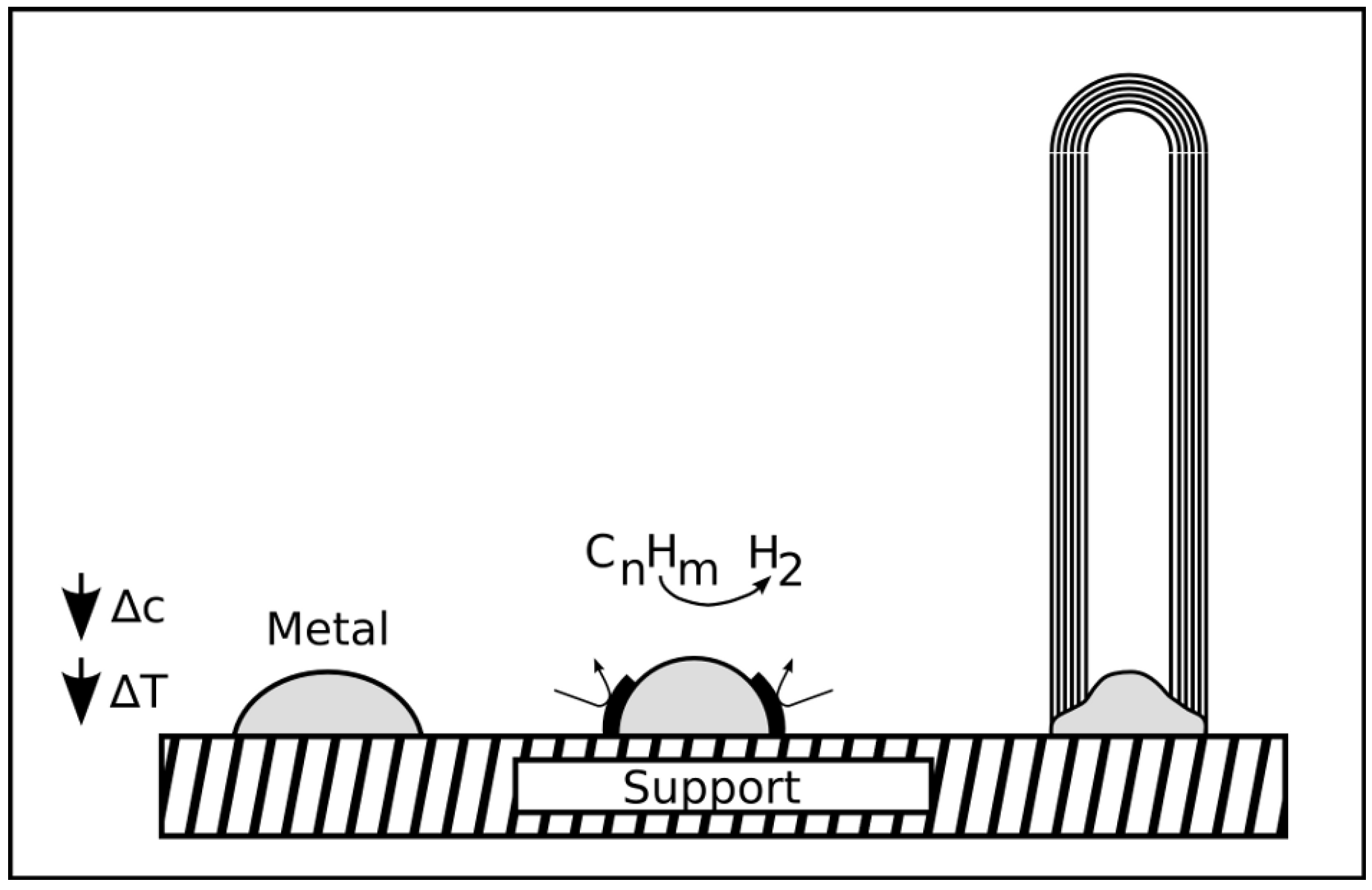
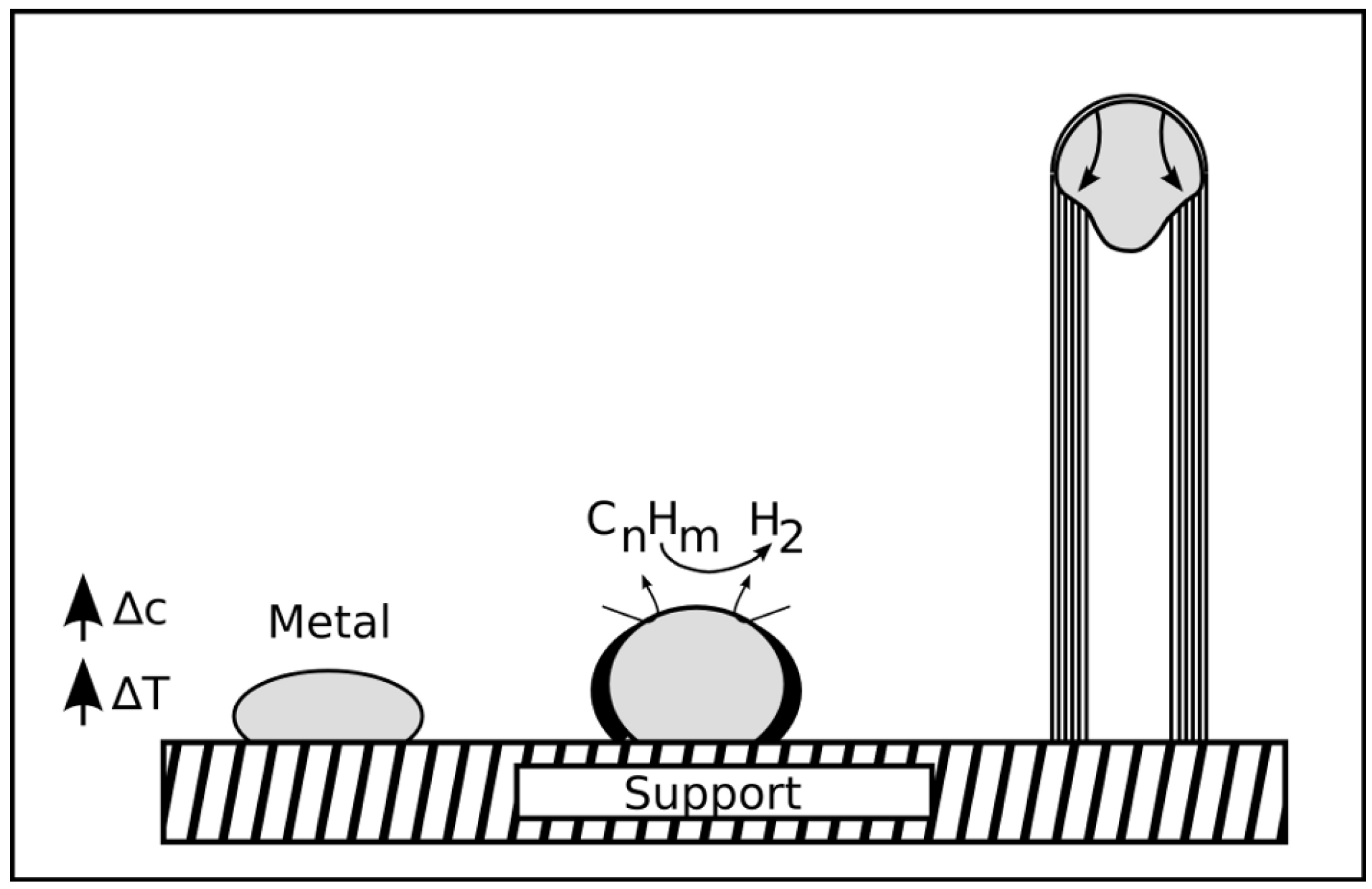
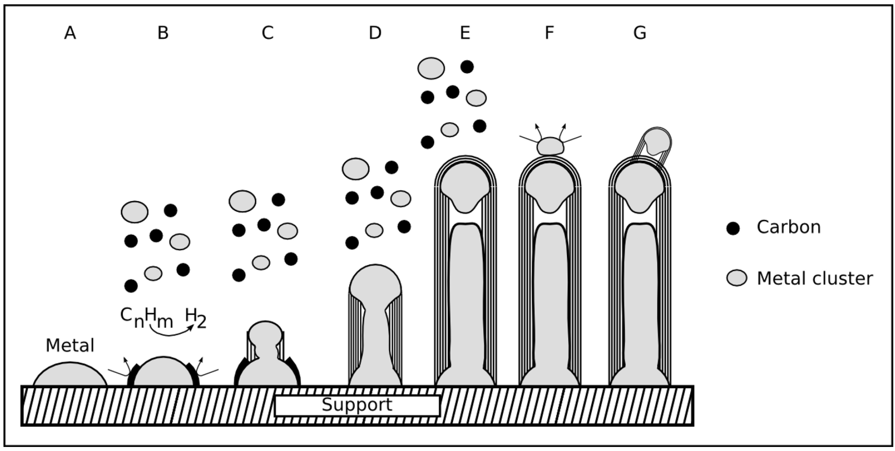
2.5. Growth mechanism
2.5.1. VLS mechanism
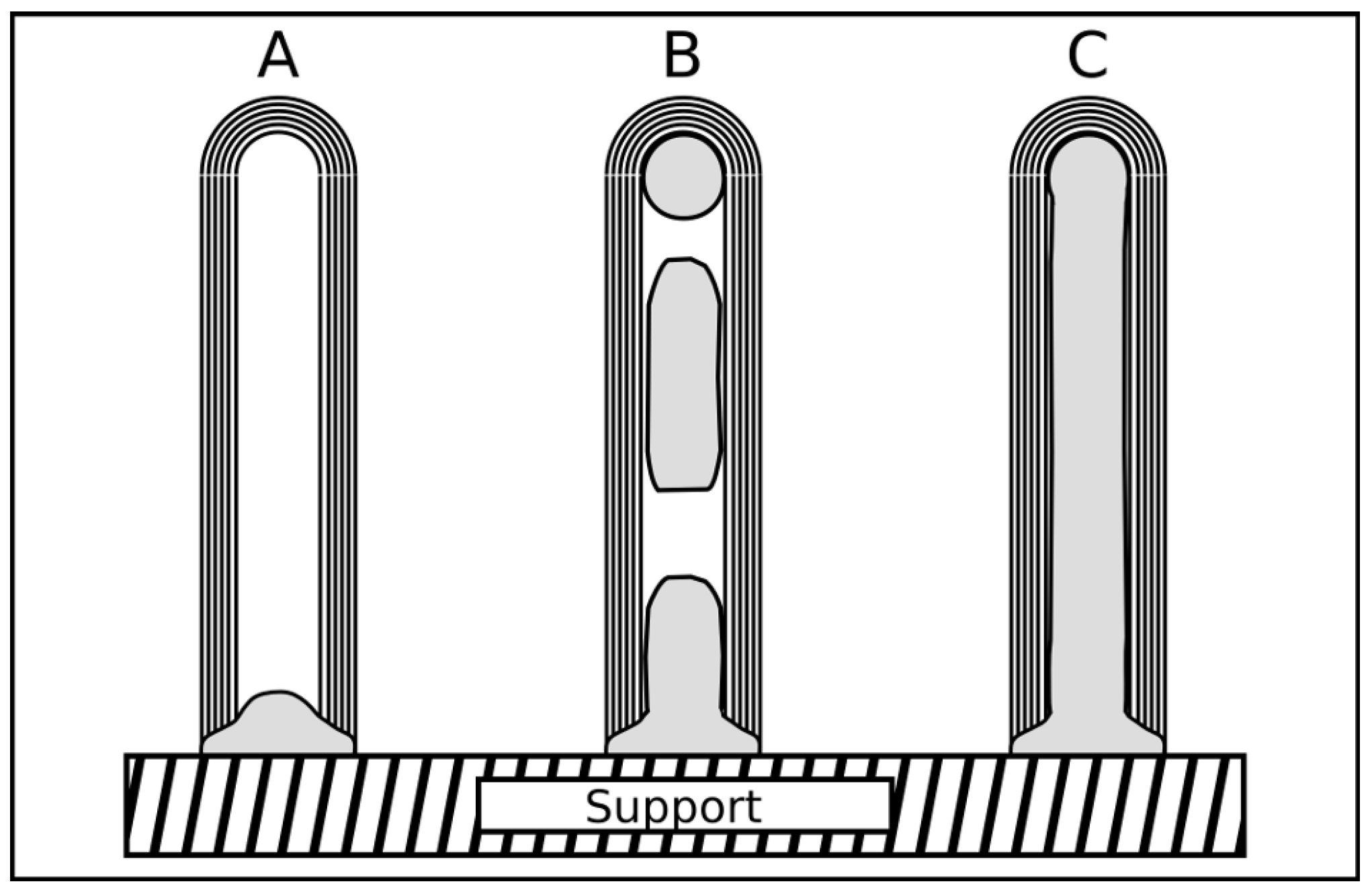
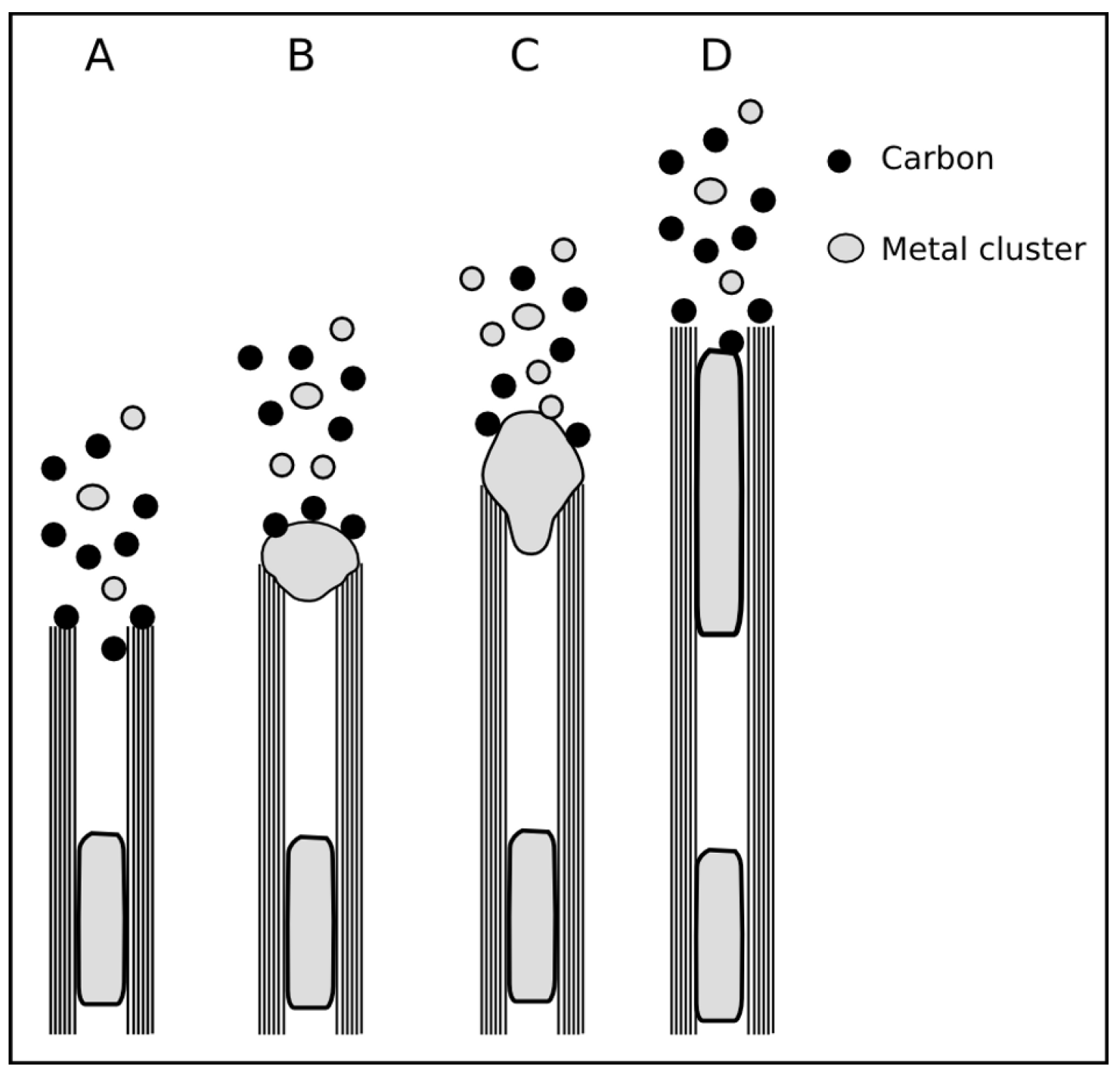
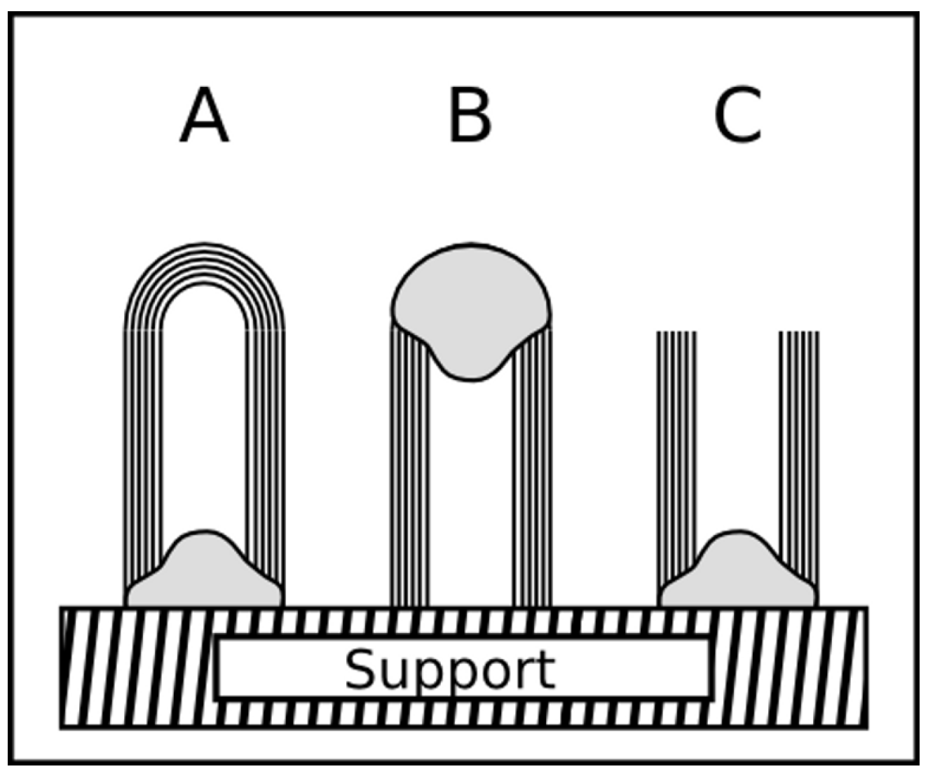
2.5.2. Base and tip growth mode


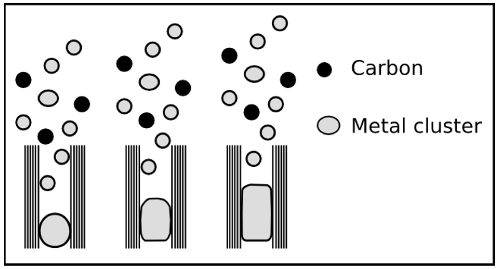
2.5.3. Base and tip growth mode for filled CNT


2.5.4. Combined growth mode

2.5.5. Conclusion
3. Properties
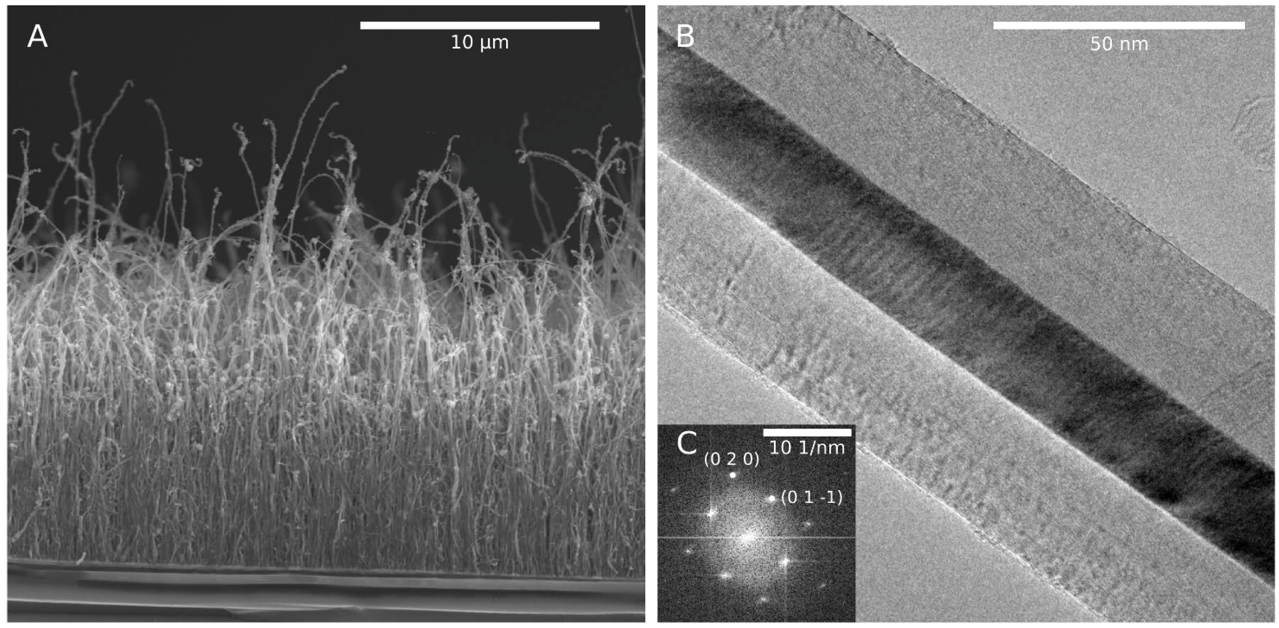
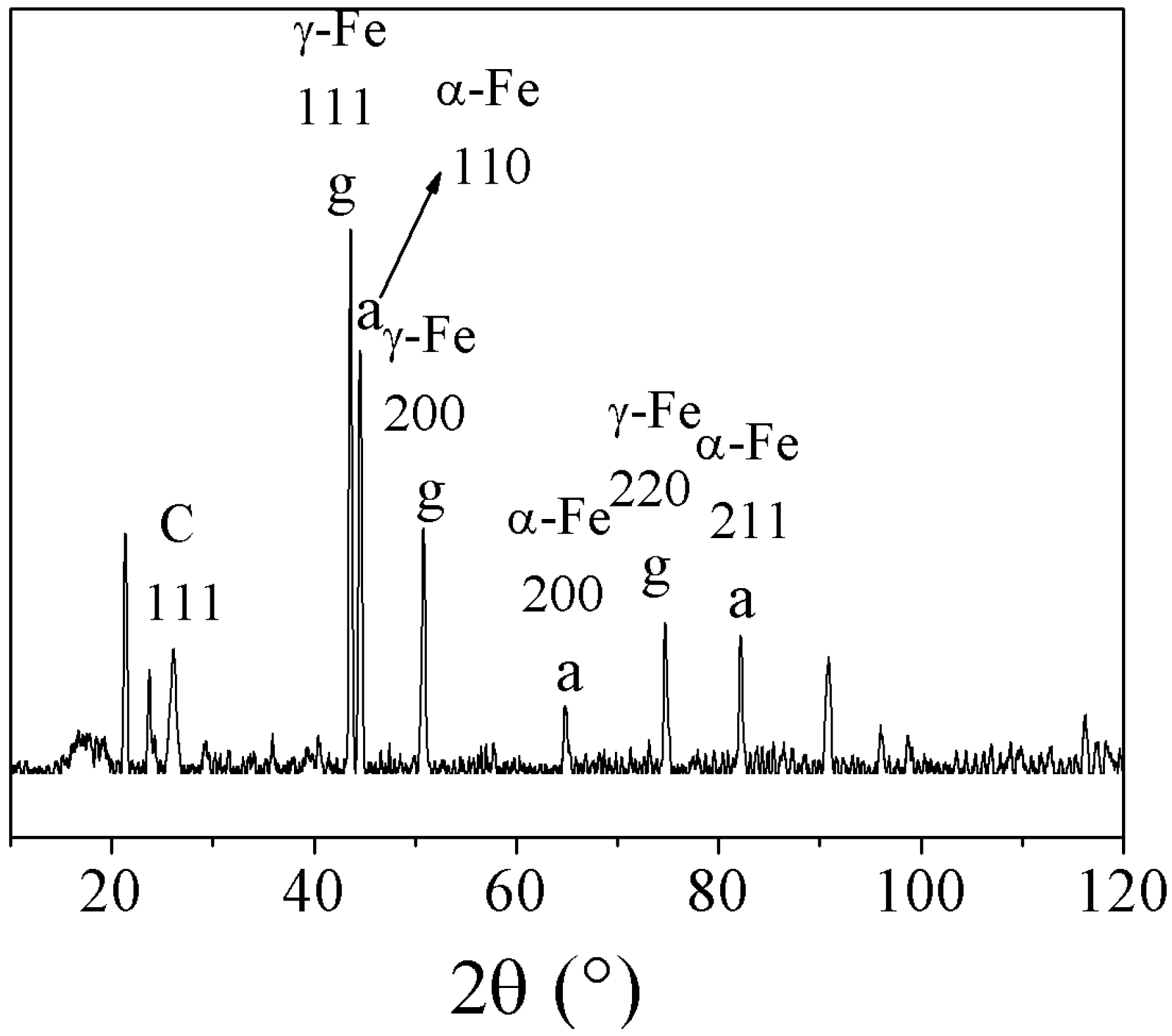
3.1. Structure


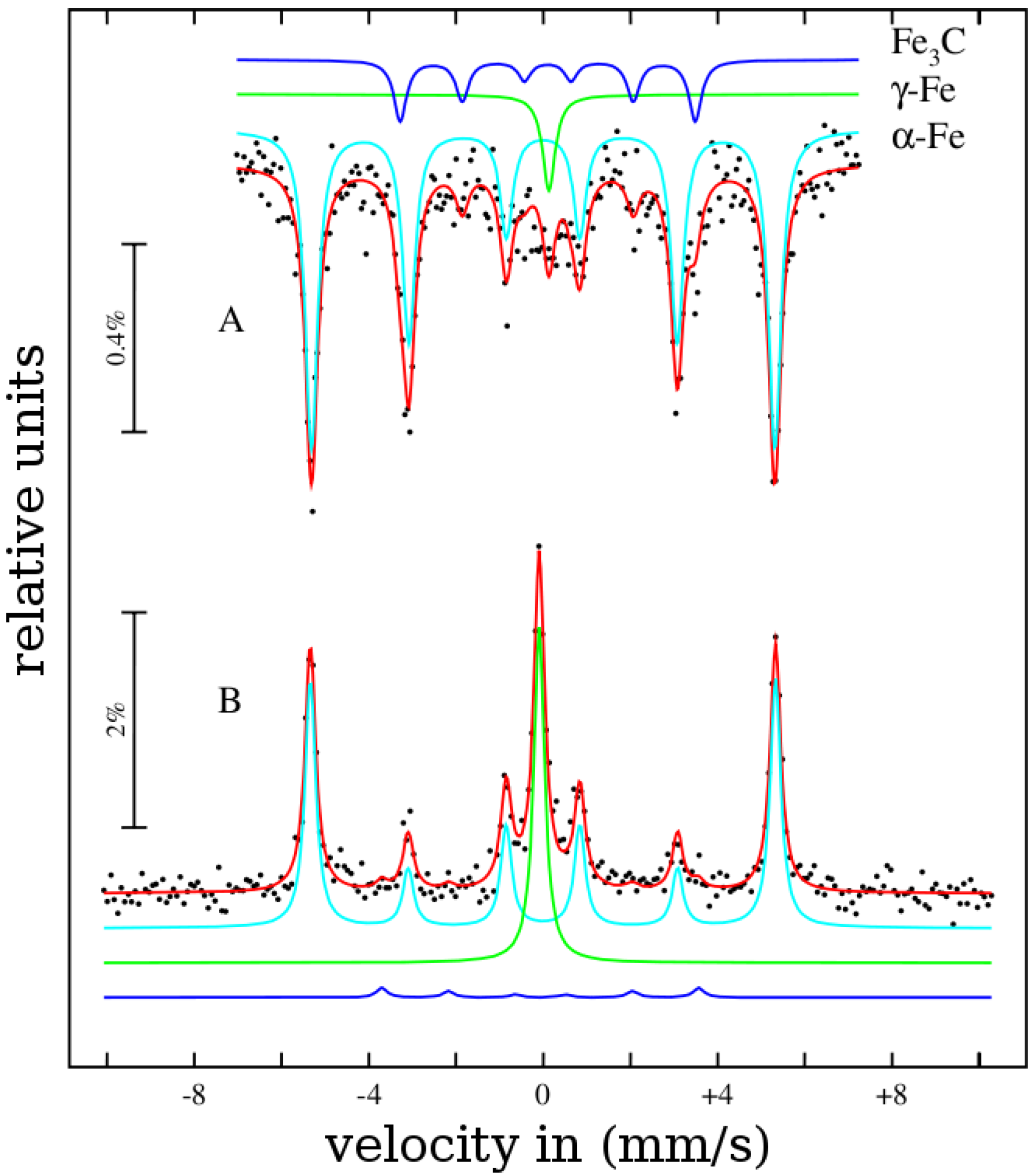
3.2. Magnetic properties
4. Applications
4.1. Medical Applications
4.2. Sensor Applications
5. Summary
Acknowledgments
References
- Iijima, S. Helical microtubeles of graphitic carbon. Nature 1991, 354, 56–58. [Google Scholar] [CrossRef]
- Iijima, S.; Ichihashi, T. Single-shell carbon nanotubes of 1-nm diameter. Nature 1993, 363, 603–605. [Google Scholar] [CrossRef]
- Ebbesen, T.W.; Ajayan, P.M. Large-scale synthesis of carbon nanotubes. Nature 1992, 358, 220. [Google Scholar] [CrossRef]
- Thess, A.; Lee, R.; Nikolaev, P.; Dai, H.; Petit, P.; Robert, J.; Xu, C.; Lee, Y.H.; Kim, G.S.; Rinzler, A.G.; Colbert, D.T.; Scuseria, G.; Tomanek, D.; Fischer, J.E.; Smalley, R.E. Crystalline Ropes of Metallic Carbon Nanotubes. Science 1996, 273, 483–487. [Google Scholar] [CrossRef] [PubMed]
- Jos´n, M.; Miki-Yoshida, M.; Rend´n, L.; Santiesteban, J.G. Catalytic growth of carbon microtubules with fullerene structure. Appl. Phys. Lett. 1993, 62, 657–659. [Google Scholar]
- Moisala, A.; Nasibulin, A.G.; Kauppinen, E.I. The role of metal nanoparticles in the catalytic production of single-walled carbon nanotubes - a review. J. Phys.: Condens. Matter 2003, 15, S3011–S3035. [Google Scholar] [CrossRef]
- Melechko, A.V.; Merkulov, V.I.; McKnight, T.E.; Guillorn, M.A.; Klein, K.L.; Lowndes, D.H.; Simpson, M.L. Vertically aligned carbon nanofibers and related structures: Controlled synthesis and directed assembly. J. Appl. Phys. 2005, 97, 041301–041339. [Google Scholar] [CrossRef]
- Leonhardt, A.; Hampel, S.; Müller, C.; Mönch, I.; Koseva, R.; Ritschel, M.; Elefant, D.; Biedermann, K.; Büchner, B. Synthesis, Properties, and Applications of Ferromagnetic-Filled Carbon Nanotubes. Chem. Vap. Deposition 2006, 12, 380–387. [Google Scholar] [CrossRef]
- Saito, R.; Dresselhaus, G.; Dresselhaus, M.S. Physical Properties of Carbon Nanotubes; Imperial College Press: London, UK, 1998. [Google Scholar]
- Thostenson, E.T.; Ren, Z.; Chou, T.W. Advances in the science and technology of carbon nanotubes and their composites: A review. Compos. Sci. Technol. 2001, 61, 1899–1912. [Google Scholar] [CrossRef]
- Tsang, S.C.; Chen, Y.K.; Harris, P.J.F.; Green, M.L.H. A simple chemical method of opening and filling carbon nanotubes. Nature 1994, 372, 159–162. [Google Scholar] [CrossRef]
- Hampel, S.; Leonhardt, A.; Selbmann, D.; Biedermann, K.; Elefant, D.; Müller, C.; Gemming, T.; Büchner, B. Growth and characterization of filled carbon nanotubes with ferromagnetic properties. Carbon 2006, 44, 2316–2322. [Google Scholar] [CrossRef]
- Kozhuharova, R.; Ritschel, M.; Mönch, I.; Mühl, T.; Leonhardt, A. Selective Growth of Aligned Co-Filled Carbon Nanotubes on Silicon Substrates. Fuller. Nanotub. Carbon Nanostr. 2005, 13, 347–353. [Google Scholar] [CrossRef]
- Monthioux, M. Filling single-wall carbon nanotubes. Carbon 2002, 40, 1809–1823. [Google Scholar] [CrossRef]
- Tasis, D.; Tagmatarchis, N.; Bianco, A.; Prato, M. Chemistry of carbon nanotubes. Chem. Rev. 2006, 106, 1105–1136. [Google Scholar] [CrossRef] [PubMed]
- Leonhardt, A.; Mönch, I.; Meye, A.; Hampel, S.; Büchner, B. Synthesis of ferromagnetic filled carbon nanotubes and their biomedical application. Adv. Sci. Technol. 2006, 49, 74–78. [Google Scholar] [CrossRef]
- Balasubramanian, K.; Burghard, M. Chemically Functionalized Carbon Nanotubes. Small 2005, 1, 180–192. [Google Scholar] [CrossRef] [PubMed]
- Klumpp, C.; Kostarelos, K.; Prato, M.; Bianco, A. Functionalized carbon nanotubes as emerging nanovectors for the delivery of therapeutics. Biochim. Biophys. Acta 2006, 1758, 404–412. [Google Scholar] [CrossRef] [PubMed]
- Tran, P.A.; Zhang, L.; Webster, T.J. Carbon nanofibers and carbon nanotubes in regenerative medicine. Adv. Drug Delivery Rev. 2009, 61, 1097–1114. [Google Scholar] [CrossRef] [PubMed]
- Bianco, A.; Kostarelos, K.; Prato, M. Applications of carbon nanotubes in drug delivery. Curr. Opin. Chem. Biol. 2005, 9, 674–679. [Google Scholar] [CrossRef] [PubMed]
- Klingeler, R.; Hampel, S.; Buechner, B. Carbon nanotube based biomedical agents for heating, temperature sensoring and drug delivery. Int. J. Hyperther. 2008, 24, 496–505. [Google Scholar] [CrossRef] [PubMed]
- Hilder, T.A.; Hill, J.M. Modeling the Loading and Unloading of Drugs into Nanotubes. Small 2009, 5, 300–308. [Google Scholar] [CrossRef] [PubMed]
- Kostarelos, K.; Bianco, A.; Prato, M. Promises, facts and challenges for carbon nanotubes in imaging and therapeutics. Nat. Nanotechnol. 2009, 4, 627–633. [Google Scholar] [CrossRef] [PubMed]
- Mönch, I.; Meye, A.; Leonhardt, A.; Krämer, K.; Kozhuharova, R.; Gemming, T.; Wirth, M.; Büchner, B. Ferromagnetic filled carbon nanotubes and nanoparticles: synthesis and lipid-mediated delivery into human tumor cells. J. Magn. Magn. Mater. 2005, 290/291, 276–278. [Google Scholar] [CrossRef]
- Kostarelos, K.; Lacerda, L.; Pastorin, G. Cellular uptake of functionalized carbon nanotubes is independent of functional group and cell type. Nat. Nanotechnol. 2007, 2, 108–113. [Google Scholar] [CrossRef] [PubMed]
- Jin, H.; Heller, D.A.; Strano, M.S. Single-Particle Tracking of Endocytosis and Exocytosis of Single-Walled Carbon Nanotubes in NIH-3T3 Cells. Nano Lett. 2008, 8, 1577–1585. [Google Scholar] [CrossRef] [PubMed]
- Son, S.J.; Bai, X.; Nan, A.; Ghandehari, H.; Lee, S.B. Template synthesis of multifunctional nanotubes for controlled release. J. Contr. Rel. 2006, 114, 143–152. [Google Scholar] [CrossRef] [PubMed]
- Lacerda, L.; Bianco, A.; Prato, M.; Kostarelos, K. Carbon nanotubes as nanomedicines: From toxicology to pharmacology. J. Contr. Rel. 2006, 58, 1460–1470. [Google Scholar] [CrossRef] [PubMed]
- Portney, N.G.; Ozkan, M. Nano-oncology: drug delivery, imaging, and sensing. Anal. Bioanal. Chem. 2006, 384, 620–630. [Google Scholar] [CrossRef] [PubMed]
- Hilder, T.A.; Hill, J.M. Modelling the encapsulation of the anticancer drug cisplatin into carbon nanotubes. J. Contr. Rel. 2006, 58, 1460–1470. [Google Scholar] [CrossRef]
- Taylor, A.; Krupskaya, Y.; Krämer, K.; Füssel, S.; Klingeler, R.; Büchner, B.; Wirth, M.P. Cisplatin-loaded carbon-encapsulated iron nanoparticles and their in vitro effects in magnetic fluid hyperthermia. Carbon 2010, 48, 2327–2334. [Google Scholar] [CrossRef]
- Ajayan, P.M.; Iijima, S. Capillarity-induced filling of carbon nanotubes. Nature 1993, 361, 333–334. [Google Scholar] [CrossRef]
- Bao, J.; Zhou, Q.; Hong, J.; Xu, Z. Synthesis and magnetic behavior of an array of nickel-filled carbon nanotubes. Appl. Phys. Lett. 2002, 81, 4592–4594. [Google Scholar] [CrossRef]
- Dyagileva, L.M.; Mar’in, V.P.; Tsyganova, E.I.; Razuvaev, G.A. Reactivity of the first transition row metallocenes in thermal decomposition reaction. J. Organomet. Chem. 1979, 175, 63–72. [Google Scholar] [CrossRef]
- Müller, C.; Golberg, D.; Leonhardt, A.; Hampel, S.; Büchner, B. Growth studies, TEM and XRD investigations of iron-filled carbon nanotubes. Phys. Status Solidi A 2006, 203, 1064–1068. [Google Scholar] [CrossRef]
- Andrews, R.; Jacques, D.; Rao, A.M.; Derbyshire, F.; Qian, D.; Fan, X.; Dickey, E.C.; Chen, J. Continuous production of aligned carbon nanotubes: a step closer to commercial realization. Chem. Phys. Lett. 1999, 303, 467–474. [Google Scholar] [CrossRef]
- Kamalakaran, R.; Terrones, M.; Seeger, T.; Kohler-Redlich, P.; Rühle, M.; Kim, Y.A.; Hayashi, T.; Endo, M. Synthesis of thick and crystalline nanotube arrays by spray pyrolysis. Appl. Phys. Lett. 2000, 77, 3385–3387. [Google Scholar] [CrossRef]
- Zhang, X.; Cao, A.; Wei, B.; Li, Y.; Wei, J.; Xu, C.; Wu, D. Rapid growth of well-aligned carbon nanotube arrays. Chem. Phys. Lett. 2002, 362, 285–290. [Google Scholar] [CrossRef]
- Nasibulin, A.G.; Moisala, A.; Brown, D.P.; Jiang, H.; Kauppinen, E.I. A novel aerosol method for single walled carbon nanotube synthesis. Chem. Phys. Lett. 2005, 402, 227–232. [Google Scholar] [CrossRef]
- Deck, C.; Vecchio, K. Growth of Well-Aligned Carbon Nanotube Structures in Successive Layers. J. Phys. Chem. B 2005, 109, 12353–12357. [Google Scholar] [CrossRef] [PubMed]
- Wang, W.; Wang, K.; Lv, R.; Wei, J.; Zhang, X.; Kang, F.; Chang, J.; Shu, Q.; Wang, Y.; Wu, D. Synthesis of Fe-filled thin-walled carbon nanotubes with high filling ratio by using dichlorobenzene as precursor. Carbon 2007, 45, 1127–1129. [Google Scholar] [CrossRef]
- Mayne, M.; Grobert, N.; Terrones, M.; Kamalakaran, R.; Rühle, M.; Kroto, H.W.; Walton, D.R.M. Pyrolytic production of aligned carbon nanotubes from homogeneously dispersed benzene-based aerosols. Chem. Phys. Lett. 2001, 338, 101–107. [Google Scholar] [CrossRef]
- Deck, C.P.; Vecchio, K. Growth mechanism of vapor phase CVD-grown multi-walled carbon nanotubes. Carbon 2005, 43, 2608–2617. [Google Scholar] [CrossRef]
- Weissker, U.; Löffler, M.; Wolny, F.; Lutz, M.U.; Scheerbaum, N.; Klingeler, R.; Gemming, T.; Mühl, T.; Leonhardt, A.; Büchner, B. Perpendicular magnetization of long iron carbide nanowires inside carbon nanotubes due to magnetocrystalline anisotropy. J. Appl. Phys. 2009, 106, 054909–054913. [Google Scholar] [CrossRef]
- Winkler, A.; Mühl, T.; Menzel, S.; Kozhuharova-Koseva, R.; Hampel, S.; Leonhardt, A.; Büchner, B. Magnetic force microscopy sensors using iron-filled carbon nanotubes. J. Appl. Phys. 2006, 99, 104905–104909. [Google Scholar] [CrossRef]
- Wolny, F.; Weissker, U.; Mühl, T.; Leonhardt, A.; Menzel, S.; Winkler, A.; Büchner, B. Iron-filled carbon nanotubes as probes for magnetic force microscopy. J. Appl. Phys. 2008, 104, 064908–064912. [Google Scholar] [CrossRef]
- Leonhardt, A.; Ritschel, M.; Kozhuharova, R.; Graff, A.; Mühl, T.; Huhle, R.; Mönch, I.; Elefant, D.; Schneider, C.M. Synthesis and properties of filled carbon nanotubes. Diamond Relat. Mater. 2003, 12, 790–793. [Google Scholar] [CrossRef]
- Gui, X.; Wei, J.; Wang, K.; Wang, W.; Lv, R.; Chang, J.; Kang, F.; Gu, J.; Wu, D. Improved filling rate and enhanced magnetic properties of Fe-filled carbon nanotubes by annealing and magnetic separation. Mater. Res. Bull. 2008, 43, 3441–3446. [Google Scholar] [CrossRef]
- Ma, X.; Cai, Y.; Li, X.; Wen, S. Growth and microstructure of Co-filled carbon nanotubes. J. Mater. Sci. Eng. 2003, 308, 308–313. [Google Scholar] [CrossRef]
- Grobert, N.; Terrones, M.; Osborne, A.; Terrones, H.; Hsu, W.; Trasobares, S.; Zhu, Y.; Hare, J.; Kroto, H.; Walton, D. Thermolysis of C60 thin films yields Ni-filled tapered nanotubes. Appl. Phys. A–Mater. 1998, 67, 595–598. [Google Scholar] [CrossRef]
- Kuwana, K.; Saito, K. Modeling CVD synthesis of carbon nanotubes: Nanoparticle formation from ferrocene. Carbon 2005, 43, 2088–2095. [Google Scholar] [CrossRef]
- Kozhuharova, R.; Ritschel, M.; Elefant, D.; Graff, A.; Mönch, I.; Mühl, T.; Schneider, C.; Leonhardt, A. (FexCo1-x)-alloy filled vertically aligned carbon nanotubes grown by thermal chemical vapor deposition. J. Magn. Magn. Mater. 2005, 290, 250–253. [Google Scholar] [CrossRef]
- Elías, A.L.; Rodríguez-Manzo, J.A.; McCartney, M.R.; Golberg, D.; Zamudio, A.; Baltazar, S.E.; López-Urías, F.; Muñoz-Sandoval, E.; Gu, L.; Tang, C.C.; Smith, D.J.; Bando, Y.; Terrones, H.; Terrones, M. Production and Characterization of Single-Crystal FeCo Nanowires Inside Carbon Nanotubes. Nano Lett. 2005, 5, 467–472. [Google Scholar] [CrossRef] [PubMed]
- Jacobs, M.H.G.; Van Ekeren, P.J.; De Kruif, C.G. The vapour pressure and enthalpy of sublimation of ferrocene. J. Chem. Thermodyn. 1983, 15, 619–623. [Google Scholar] [CrossRef]
- Torres-Gómez, L.A.; Barreiro-Rodríquez, G.; Méndez-Ruíz, F. Vapour pressures and enthalpies of sublimation of ferrocene, cobaltocene and nickelocene. Thermochim. Acta 1988, 124, 179–183. [Google Scholar] [CrossRef]
- Emel’yanenko, V.N.; Verevkin, S.P.; Krol, O.V.; Varushchenko, R.M.; Chelovskaya, N.V. Vapour pressures and enthalpies of vaporization of a series of the ferrocene derivatives. J. Chem. Thermodyn. 2007, 39, 594–601. [Google Scholar] [CrossRef]
- Sen, R.; Govindaraj, A.; Rao, C.N.R. Carbon nanotubes by the metallocene route. Chem. Phys. Lett. 1997, 267, 276–280. [Google Scholar] [CrossRef]
- Rao, C.N.R.; Sen, R.; Satishkumar, B.C.; Govindaraj, A. Large aligned-nanotube bundles from ferrocene pyrolysis. Chem. Commun. 1998, 15, 1525–1526. [Google Scholar] [CrossRef]
- Gui, X.; Wang, K.; Wang, W.; Wei, J.; Zhang, X.; Lv, R.; Jia, Y.; Shu, Q.; Kang, F.; Wu, D. The decisive roles of chlorine-contained precursor and hydrogen for the filling Fe nanowires into carbon nanotubes. Mater. Chem. Phys. 2009, 113, 634–637. [Google Scholar] [CrossRef]
- Vander Wal, R.L.; Ticich, T.M.; Curtis, V.E. Substrate-support interactions in metal-catalyzed carbon nanofiber growth. Carbon 2001, 39, 2277–2289. [Google Scholar] [CrossRef]
- Dupuis, A.C. The catalyst in the CCVD of carbon nanotubes—a review. Prog. Mater. Sci. 2005, 50, 929–961. [Google Scholar] [CrossRef]
- Chen, Y.; Huang, J.; Hu, J.; Yang, C.; Kang, W. Synthesis of single-walled carbon nanotubes produced using a three layer Al/Fe/Mo metal catalyst and their field emission properties. Carbon 2007, 45, 3007–3014. [Google Scholar] [CrossRef]
- Kappen, P.; Halstead, B.; Rider, A.; Pigram, P.J.; Brack, N. Multi-Walled Carbon Nanotubes Grown from Chemical Vapor: Links between Atomic near Range Order and Growth Parameters. J. Phys. Chem. C 2009, 113, 4307–4314. [Google Scholar] [CrossRef]
- Molenbroek, A.M.; Helveg, S.; Topsoe, H.; Clausen, B.S. Nano-Particles in Heterogeneous Catalysis. Top Catal. 2009, 52, 1303–1311. [Google Scholar] [CrossRef]
- Endo, H.; Kuwana, K.; Saito, K.; Qian, D.; Andrews, R.; Grulke, E.A. CFD prediction of carbon nanotube production rate in a CVD reactor. Chem. Phys. Lett. 2004, 387, 307–311. [Google Scholar] [CrossRef]
- Ng, H.T.; Chen, B.; Koehne, J.E.; Cassell, A.M.; Li, J.; Han, J.; Meyyappan, M. Growth of Carbon Nanotubes: A Combinatorial Method To Study the Effects of Catalysts and Underlayers. J. Phys. Chem. B. 2003, 107, 8484–8489. [Google Scholar] [CrossRef]
- Müller, C.; Hampel, S.; Elefant, D.; Biedermann, K.; Leonhardt, A.; Ritschel, M.; Büchner, B. Iron filled carbon nanotubes grown on substrates with thin metal layers and their magnetic properties. Carbon 2006, 44, 1746–1753. [Google Scholar] [CrossRef]
- Mo, Y.; Kibria, A.; Nahm, K. The growth mechanism of carbon nanotubes from thermal cracking of acetylene over nickel catalyst supported on alumina. Synth. Met. 2001, 122, 443–447. [Google Scholar] [CrossRef]
- Hongo, H.; Nihey, F.; Ichihashi, T.; Ochiai, Y.; Yudasaka, M.; Iijima, S. Support materials based on converted aluminum films for chemical vapor deposition growth of single-wall carbon nanotubes. Chem. Phys. Lett. 2003, 380, 158–164. [Google Scholar] [CrossRef]
- Song, I.K.; Yu, W.J.; Cho, Y.S.; Choi, G.S.; Kim, D. The determining factors for the growth mode of carbon nanotubes in the chemical vapour deposition process. Nanotechnology 2004, 15, 590–595. [Google Scholar] [CrossRef]
- Müller, C.; Leonhardt, A.; Hampel, S.; Büchner, B. Diameter controlled growth of iron-filled carbon nanotubes. Phys. Status Solidi B 2006, 243, 3091–3094. [Google Scholar] [CrossRef]
- Iijima, S.; Ajayan, P.M.; Ichihashi, T. Growth model for carbon nanotubes. Phys. Rev. Lett. 1992, 69, 3100–3103. [Google Scholar] [CrossRef] [PubMed]
- Sinnott, S.; Andrews, R.; Qian, D.; Rao, A.; Mao, Z.; Dickey, E.; Derbyshire, F. Model of carbon nanotube growth through chemical vapor deposition. Chem. Phys. Lett. 1999, 315, 25–30. [Google Scholar] [CrossRef]
- Zhang, G.Y.; Wang, E.G. Cu-filled carbon nanotubes by simultaneous plasma-assisted copper incorporation. Appl. Phys. Lett. 2003, 82, 1926–1928. [Google Scholar] [CrossRef]
- Kabir, M.S.; Morjan, R.E.; Nerushev, O.A.; Lundgren, P.; Bengtsson, S.; Enoksson, P.; Campbell, E.E.B. Fabrication of individual vertically aligned carbon nanofibres on metal substrates from prefabricated catalyst dots. Nanotechnology 2006, 17, 790–794. [Google Scholar] [CrossRef]
- Mönch, I.; Kozhuharova-Koseva, R.; Rümmeli, M.; Elefant, D.; Gemming, T.; Kaltofen, R.; Leonhardt, A.; Schäfer, T.; Büchner, B. Selective growth of vertically aligned Fe-filled carbon nanotubes on oxidized silicon substrates. J. Phys. Conf. Ser. 2007, 61, 815–819. [Google Scholar] [CrossRef]
- Esconjauregui, S.; Whelan, C.M.; Maex, K. The reasons why metals catalyze the nucleation and growth of carbon nanotubes and other carbon nanostructures. Carbon 2009, 47, 659–669. [Google Scholar] [CrossRef]
- Gavillet, J.; Thibault, J.; St´phan, O.; Amara, H.; Loiseau, A.; Bichara, C.; Gaspard, J.P.; Ducastelle, F. Nucleation and Growth of Single-Walled Nanotubes: The Role of Metallic Catalysts. J. Nanosci. Nanotechnol. 2004, 4, 346–359. [Google Scholar] [CrossRef] [PubMed]
- Schouten, F.; Gijzeman, O.; Bootsma, G. Interaction of methane with Ni(111) and Ni(100); diffusion of carbon into nickel through the (100) surface; An aes-leed study. Surf. Sci. 1979, 87, 1–12. [Google Scholar] [CrossRef]
- Audier, M.; Oberlin, A.; Coulon, M. Crystallographic orientations of catalytic particles in filamentous carbon; Case of simple conical particles. J. Cryst. Growth 1981, 55, 549–556. [Google Scholar] [CrossRef]
- Vanfleet, R.R.; Mochel, J.M. Thermodynamics of melting and freezing in small particles. Surf. Sci. 1995, 341, 40–50. [Google Scholar] [CrossRef]
- Loiseau, A.; Willaime, F. Filled and mixed nanotubes: from TEM studies to the growth mechanism within a phase-diagram approach. Appl. Surf. Sci. 2000, 164, 227–240. [Google Scholar] [CrossRef]
- Wen, J.; Huang, Z.; Wang, D.; Chen, J.; Yang, S.; Ren, Z.; Wang, J.; Calvet, L.; Chen, J.; Klemic, J.; Reed, M. Growth and characterization of aligned carbon nanotubes from patterned nickel nanodots and uniform thin films. J. Mater. Res. 2001, 16, 3246–3253. [Google Scholar] [CrossRef]
- Loiseau, A.; Gavillet, J.; Ducastelle, F.; Thibault, J.; Stephan, O.; Bernier, P.; Thair, S. Nucleation and growth of SWNT: TEM studies of the role of the catalyst. C. R. Phys. 2003, 4, 975–991. [Google Scholar] [CrossRef]
- Müller, C.; Leonhardt, A.; Kutz, M.C.; Reuther, H.; Büchner, B. Growth Aspects of Iron-Filled Carbon Nanotubes Obtained by Catalytic Chemical Vapor Deposition of Ferrocene. J. Phys. Chem. C 2009, 113, 2736–2740. [Google Scholar] [CrossRef]
- Leonhardt, A.; Ritschel, M.; Elefant, D.; Mattern, N.; Biedermann, K.; Hampel, S.; Müller, C.; Gemming, T.; Büchner, B. Enhanced magnetism in Fe-filled carbon nanotubes produced by pyrolysis of ferrocene. J. Appl. Phys. 2005, 98, 074315–074319. [Google Scholar] [CrossRef]
- Kuwana, K.; Endo, H.; Saito, K.; Qian, D.; Andrews, R.; Grulke, E.A. Catalyst deactivation in CVD synthesis of carbon nanotubes. Carbon 2005, 43, 253–260. [Google Scholar] [CrossRef]
- Kuwana, K.; Li, T.; Saito, K. Gas-phase reactions during CVD synthesis of carbon nanotubes: Insights via numerical experiments. Chem. Eng. Sci. 2006, 61, 6718–6726. [Google Scholar] [CrossRef]
- Kuwana, K.; Saito, K. Modeling ferrocene reactions and iron nanoparticle formation: Application to CVD synthesis of carbon nanotubes. Proc. Combust. Inst. 2007, 31, 1857–1864. [Google Scholar] [CrossRef]
- Singh, C.; Shaffer, M.S.P.; Windle, A.H. Production of controlled architectures of aligned carbon nanotubes by an injection chemical vapour deposition method. Carbon 2003, 41, 359–368. [Google Scholar] [CrossRef]
- Nerushev, O.A.; Sveningsson, M.; Falk, L.K.L.; Rohmund, F. Carbon nanotube films obtained by thermal chemical vapour deposition. J. Mater. Chem. 2001, 11, 1122–1132. [Google Scholar] [CrossRef]
- Hernadi, K.; Fonseca, A.; Nagy, J.B.; Bernaerts, D.; Lucas, A.A. Fe-catalyzed carbon nanotube formation. Carbon 1996, 34, 1249–1257. [Google Scholar] [CrossRef]
- Reilly, P.T.; Whitten, W.B. The role of free radical condensates in the production of carbon nanotubes during the hydrocarbon CVD process. Carbon 2006, 44, 1653–1660. [Google Scholar] [CrossRef]
- Juang, Z.Y.; Lai, J.F.; Weng, C.H.; Lee, J.H.; Lai, H.J.; Lai, T.S.; Tsai, C.H. On the kinetics of carbon nanotube growth by thermal CVD method. Diamond Relat. Mater. 2004, 13, 2140–2146. [Google Scholar] [CrossRef]
- Wasel, W.; Kuwana, K.; Reilly, P.T.; Saito, K. Experimental characterization of the role of hydrogen in CVD synthesis of MWCNTs. Carbon 2007, 45, 833–838. [Google Scholar] [CrossRef]
- Ding, F.; Bolton, K.; Rosen, A. Iron-carbide cluster thermal dynamics for catalyzed carbon nanotube growth. J. Vac. Sci. Technol. A 2004, 22, 1471–1476. [Google Scholar] [CrossRef]
- Wagner, R.S.; Ellis, W.C. Vapor-Liquid-Solid Mechanism of Single Crystal Growth. Appl. Phys. Lett. 1964, 4, 89–90. [Google Scholar] [CrossRef]
- Baker, R.T.K. Nucleation and growth of carbon deposits from the nickel catalyzed decomposition of acetylene. J. Catal. 1972, 26, 51–62. [Google Scholar] [CrossRef]
- Baker, R.T.K. Catalytic growth of carbon filaments. Carbon 1989, 27, 315–323. [Google Scholar] [CrossRef]
- Hofmann, S.; Csanyi, G.; Ferrari, A.C.; Payne, M.C.; Robertson, J. Surface Diffusion: The Low Activation Energy Path for Nanotube Growth. Phys. Rev. Lett. 2005, 95, 036101–036104. [Google Scholar] [CrossRef] [PubMed]
- Kwon, Y.K.; Lee, Y.H.; Kim, S.G.; Jund, P.; Tománek, D.; Smalley, R.E. Morphology and Stability of Growing Multiwall Carbon Nanotubes. Phys. Rev. Lett. 1997, 79, 2065–2068. [Google Scholar] [CrossRef]
- Lee, Y.H.; Kim, S.G.; Tománek, D. Catalytic Growth of Single-Wall Carbon Nanotubes: An Ab Initio Study. Phys. Rev. Lett. 1997, 78, 2393–2396. [Google Scholar] [CrossRef]
- Ding, F.; Bolton, K.; Ros´n, A. Nucleation and Growth of Single-Walled Carbon Nanotubes: A Molecular Dynamics Study. J. Phys. Chem. B 2004, 108, 17369–17377. [Google Scholar] [CrossRef]
- Nardelli, M.B.; Brabec, C.; Maiti, A.; Roland, C.; Bernholc, J. Lip-Lip Interactions and the Growth of Multiwalled Carbon Nanotubes. Phys. Rev. Lett. 1998, 80, 313–316. [Google Scholar] [CrossRef]
- Nardelli, M.B.; Roland, C.; Bernholc, J. Theoretical bounds for multiwalled carbon nanotube growth. Chem. Phys. Lett. 1998, 296, 471–476. [Google Scholar] [CrossRef]
- Charlier, J.C.; Amara, H.; Lambin, P. Catalytically Assisted Tip Growth Mechanism for Single-Wall Carbon Nanotubes. ACS Nano 2007, 1, 202–207. [Google Scholar] [CrossRef] [PubMed]
- Ding, F.; Rosen, A.; Bolton, K. Molecular dynamics study of the catalyst particle size dependence on carbon nanotube growth. J. Chem. Phys. 2004, 121, 2775–2779. [Google Scholar] [CrossRef] [PubMed]
- Kunadian, I.; Andrews, R.; Qiana, D.; Mengüc, M.P. Growth kinetics of MWCNTs synthesized by a continuous-feed CVD method. Carbon 2009, 47, 384–395. [Google Scholar] [CrossRef]
- Kozhuharova, R.; Ritschel, M.; Elefant, D.; Graff, A.; Leonhardt, A.; Mönch, I.; Mühl, T.; Schneider, C.M. Synthesis and characterization of aligned Fe-filled carbon nanotubes on silicon substrates. J. Mater. Sci. 2003, 14, 789–791. [Google Scholar]
- Marco, J.F.; Gancedo, J.R.; Hernando, A.; Crespo, P.; Prados, C.; Gonzales, J.M.; Gobert, N.; Terrones, M.; Walton, D.R.M.; Kroto, H.W. Mössbauer study of iron-containing carbon nanotubes. Hyperfine Interactions 2002, 139/140, 535–542. [Google Scholar] [CrossRef]
- Grobert, N.; Hsu, W.K.; Zhu, Y.Q.; Hare, J.P.; Kroto, H.W.; Walton, D.R.M.; Terrones, M.; Terrones, H.; Redlich, P.; Rühle, M.; Escudero, R.; Morales, F. Enhanced magnetic coercivities in Fe nanowires. Appl. Phys. Lett. 1999, 75, 3363–3365. [Google Scholar] [CrossRef]
- Schaper, A.K.; Hou, H.; Greiner, A.; Phillipp, F. The role of iron carbide in multiwalled carbon nanotube growth. J. Catal. 2004, 222, 250–254. [Google Scholar] [CrossRef]
- Golberg, D.; Mitome, M.; Müller, C.; Tang, C.; Leonhardt, A.; Bando, Y. Atomic structures of iron-based single-crystalline nanowires crystallized inside multi-walled carbon nanotubes as revealed by analytical electron microscopy. Acta Mater. 2006, 54, 2567–2576. [Google Scholar] [CrossRef]
- Yoshida, H.; Takeda, S.; Uchiyama, T.; Kohno, H.; Homma, Y. Atomic-Scale In-situ Observation of Carbon Nanotube Growth from Solid State Iron Carbide Nanoparticles. Nano Lett. 2008, 8, 2082–2086. [Google Scholar] [CrossRef] [PubMed]
- Kozhuharova, R.; Ritschel, M.; Elefant, D.; Graff, A.; Leonhardt, A.; Mönch, I.; Mühl, T.; Groudeva-Zotova, S.; Schneider, C.M. Well-aligned Co-filled carbon nanotubes: Preparation and magnetic properties. Appl. Surf. Sci. 2004, 238, 355–359. [Google Scholar] [CrossRef]
- Helveg, S.; Hansen, P.L. Atomic-scale studies of metallic nanocluster catalysts by in situ high-resolution transmission electron microscopy. Catal. Today 2006, 111, 68–73. [Google Scholar] [CrossRef]
- Ruskov, T.; Spirov, I.; Ritschel, M.; Müller, C.; Leonhardt, A.; Ruskov, R. Mössbauer morphological analysis of Fe-filled multiwalled carbon nanotube samples. J. Appl. Phys. 2006, 100, 084326–8. [Google Scholar] [CrossRef]
- Prados, C.; Crespo, P.; Gonzalez, J.M.; Hernando, A.; Marco, J.F.; Gancedo, R.; Grobert, N.; Terrones, M.; Walton, R.M.; Kroto, H.W. Hysteresis shift in Fe-filled carbon nanotubes due to γ-Fe. Phys. Rev. B 2002, 65, 113405–113408. [Google Scholar] [CrossRef]
- Geng, F.; Cong, H. Fe-filled carbon nanotube array with high coercivity. Physica B 2006, 382, 300–304. [Google Scholar] [CrossRef]
- Lutz, M.U.; Weissker, U.; Wolny, F.; Müller, C.; Löffler, M.; Mühl, T.; Leonhardt, A.; Büchner, B.; Klingeler, R. Magnetic properties of α-Fe and Fe3C nanowiress. J. Phys. Conf. Ser. 2010, 200, 072062–072065. [Google Scholar] [CrossRef]
- Mühl, T.; Elefant, D.; Graff, A.; Kozhuharova, R.; Leonhardt, A.; Mönch, I.; Ritschel, M.; Simon, P.; Groudeva-Zotova, S.; Schneider, C.M. Magnetic properties of aligned Fe-filled carbon nanotubes. J. Appl. Phys. 2003, 93, 7894–7896. [Google Scholar] [CrossRef]
- Fujita, T.; Chen, M.; Wang, X.; Xu, B.; Inoke, K.; Yamamoto, K. Electron holography of single-crystal iron nanorods encapsulated in carbon nanotubes. J. Appl. Phys. 2007, 101, 014323–014327. [Google Scholar] [CrossRef]
- Hayashi, Y.; Fujita, T.; Tokunaga, T.; Kaneko, K.; Tanemura, M.; Butler, T.; Rupesinghe, N.; Carey, J.; Silva, S.; Teo, K.; Amaratunga, G. Microstructure and local magnetic induction of segmented and alloyed Pd/Co nanocomposites encapsulated inside vertically aligned multiwalled carbon nanotubes. Diamond Relat. Mater. 2008, 17, 1525–1528. [Google Scholar] [CrossRef]
- Nepijko, S.; Graff, A.; Schönhense, G.; Schneider, C. Quantitative determination of magnetic fields from iron particles of oblong form encapsulated by carbon nanotubes using electron holography. Appl. Phys. A. 2009, 94, 543–547. [Google Scholar] [CrossRef]
- Banerjee, P.; Wolny, F.; Pelekhov, D.V.; Herman, M.R.; Fong, K.C.; Weissker, U.; Mühl, T.; Obukhov, Y.; Leonhardt, A.; Büchner, B.; Hammel, P.C. Magnetization Reversal in an Individual 25 nm Iron-Filled Carbon Nanotube. Appl. Phys. Lett. 2010, 96, 252505–252507. [Google Scholar] [CrossRef]
- Skomski, R. Nanomagnetics. J. Phys.: Condens. Matter 2003, 15, R841–R896. [Google Scholar] [CrossRef]
- Lyubutin, I.S.; Frolov, K.V.; Anosova, O.A.; Pokatilov, V.S.; Okotrub, A.V.; Kudashov, A.G.; Shubin, Y.V.; Bulusheva, L.G. Phase States and Magnetic Properties of Iron Nanoparticles in Carbon Nanotube Channels. J. Exp. Theor. Phys. 2009, 109, 254–261. [Google Scholar] [CrossRef]
- Karmakar, S.; Sharma, S.M.; Mukadam, M.D.; Yusuf, S.M.; Sood, A.K. Magnetic behavior of iron-filled multiwalled carbon nanotubes. J. Appl. Phys. 2005, 97, 054306–054310. [Google Scholar] [CrossRef]
- Jo, C.; Lee, J.I. Magnetism of Fe, Co, and Ni nanowires encapsulated in carbon nanotubes. J. Magn. Magn. Mater. 2008, 320, 3256–3260. [Google Scholar] [CrossRef]
- Kang, Y.J.; Choi, J.; Moon, C.Y.; Chang, K.J. Electronic and magnetic properties of single-wall carbon nanotubes filled with iron atoms. Phys. Rev. B 2005, 71, 115441–115447. [Google Scholar] [CrossRef]
- Ivanovskaya, V.V.; Kohler, C.; Seifert, G. 3d metal nanowires and clusters inside carbon nanotubes: Structural, electronic, and magnetic properties. Phys. Rev. B 2007, 75, 075410–075416. [Google Scholar] [CrossRef]
- Weissmann, M.; Garc´a, G.; Kiwi, M.; Ram´rez, R.; Fu, C.C. Theoretical study of iron-filled carbon nanotubes. Phys. Rev. B 2006, 73, 125435–125442. [Google Scholar] [CrossRef]
- Vo, T.; Wu, Y.D.; Car, R.; Robert, M. Structures, Interactions, and Ferromagnetism of Fe-Carbon Nanotube Systems. J. Phys. Chem. C 2008, 112, 8400–8407. [Google Scholar] [CrossRef]
- Li, Y.; Kaneko, T.; Ogawa, T.; Takahashib, M.; Hatakeyamaa, R. Magnetic characterization of Fe-nanoparticles encapsulated single-walled carbon nanotubes. Chem. Commun. 2007, 254–256. [Google Scholar]
- Borowiak-Palen, E.; Mendoza, E.; Bachmatiuk, A.; Rummeli, M.; Gemming, T.; Nogues, J.; Skumryev, V.; Kalenczuk, R.; Pichler, T.; Silva, S. Iron filled single-wall carbon nanotubes - A novel ferromagnetic medium. Chem. Phys. Lett. 2006, 421, 129–133. [Google Scholar] [CrossRef]
- Jorge, J.; Flahaut, E.; Gonzalez-Jimenez, F.; Gonzalez, G.; Gonzalez, J.; Belandria, E.; Broto, J.M.; Raquet, B. Preparation and characterization of α-Fe nanowires located inside double wall carbon nanotubes. Chem. Phys. Lett. 2008, 457, 347–351. [Google Scholar] [CrossRef] [Green Version]
- Johannsen, M.; Thiesen, B.; Jordan, A.; Taymoorian, K.; Gneveckow, U.; Waldöfner, N.; Scholz, R.; Koch, M.; Lein, M.; Jung, K.; Loening, S.A. Magnetic fluid hyperthermia (MFH) reduces prostate cancer growth in the orthotopic Dunning R3327 rat model. The Prostate 2005, 64, 283–292. [Google Scholar] [CrossRef] [PubMed]
- Matsuoka, F.; Shinkai, M.; Honda, H.; Kubo, T.; Sugita, T.; Kobayashi, T. Hyperthermia using magnetite cationic liposomes for hamster osteosarcoma. Biomagn. Res. Technol. 2004, 2:3, 1–6. [Google Scholar] [CrossRef] [PubMed]
- Johannsen, M.; Gneveckow, U.; Taymoorian, K.; Thiesen, B.; Waldöfner, N.; Scholz, R.; Jung, K.; Jordan, A.; Wust, P.; Loening, S.A. Morbidity and quality of life during thermotherapy using magnetic nanoparticles in locally recurrent prostate cancer: Results of a prospective phase I trial. Int. J. Hyperther. 2007, 23, 315–323. [Google Scholar] [CrossRef] [PubMed]
- Jordan, A.; Scholz, R.; Wust, P.; Fahling, H.; Felix, R. Magnetic fluid hyperthermia (MFH): Cancer treatment with AC magnetic field induced excitation of biocompatible superparamagnetic nanoparticles. J. Magn. Magn. Mat. 1999, 201, 413–419. [Google Scholar] [CrossRef]
- Krupskaya, Y.; Mahn, C.; Parameswaran, A.; Taylor, A.; Krämer, K.; Hampel, S.; Leonhardt, A.; Ritschel, M.; Büchner, B.; Klingeler, R. Magnetic study of iron-containing carbon nanotubes: Feasibility for magnetic hyperthermia. J. Magn. Magn. Mater. 2009, 321, 4067–4071. [Google Scholar] [CrossRef]
- Gneveckow, U.; Jordan, A.; Scholz, R.; Brüß, V.; Waldöfner, N.; Ricke, J.; Feussner, A.; Hildebrandt, B.; Rau, B.; Wust, P. Description and characterization of the novel hyperthermia- and thermoablation-system MFH (R) 300F for clinical magnetic fluid hyperthermia. Med. Phys. 2004, 31, 1444–1451. [Google Scholar] [CrossRef] [PubMed]
- Vyalikh, A.; Wolter, A.; Hampel, S.; Haase, D.; Ritschel, M.; Leonhardt, A.; Grafe, H.J.; Taylor, A.; Kraemer, K.; Buechner, B.; Klingeler, R. A carbon-wrapped nanoscaled thermometer for temperature control in biological environments. Nanomedicine 2008, 3, 321–327. [Google Scholar] [CrossRef] [PubMed]
- Choi, J.H.; Nguyen, F.T.; Barone, P.W.; Heller, D.A.; Moll, A.E.; Patel, D.; Boppart, S.A.; Strano, M.S. Multimodal Biomedical Imaging with Asymmetric Single-Walled Carbon Nanotube/Iron Oxide Nanoparticle Complexes. Nano Lett. 2007, 7, 861–867. [Google Scholar] [CrossRef] [PubMed]
- Ananta, J.S.; Matson, M.L.; Tang, A.M.; Mandal, T.; Lin, S.; Wong, K.; Wong, S.T.; Wilson, L.J. Single-Walled Carbon Nanotube Materials as T2-Weighted MRI Contrast Agents. J. Phys. Chem. 2009, 113, 19369–19372. [Google Scholar]
- Hampel, S.; Kunze, D.; Haase, D.; Kraemer, K.; Rauschenbach, M.; Ritschel, M.; Leonhardt, L.; Thomas, J.; Oswald, S.; Hoffmann, V.; Buechner, B. Carbon nanotubes filled with a chemotherapeutic agent: A nanocarrier mediates inhibition of tumor cell growth. Nanomedicine 2008, 2, 175–182. [Google Scholar] [CrossRef] [PubMed]
- Cai, D.; Blair, D.; Dufort, F.J.; Gumina, M.R.; Huang, Z.; Hong, G.; Wagner, D.; Canahan, D.; Kempa, K.; Ren, Z.F.; Chiles, T.C. Interaction between carbon nanotubes and mammalian cells: characterization by flow cytometry and application. Nanotechnology 2008, 19, 345102–345111. [Google Scholar] [CrossRef] [PubMed]
- Raffa, V.; Vittorio, O.; Ciofani, G.; Pensabene, V.; Cuschieri, A. Cell Creeping and Controlled Migration by Magnetic Carbon Nanotubes. Nanoscale Res. Lett. 2010, 5, 257–262. [Google Scholar] [CrossRef] [PubMed]
- Raffa, V.; Ciofani, G.; Vittorio, O.; Pensabene, V.; Cuschieri, A. Carbon nanotube-enhanced cell electropermeabilisation. Bioelectrochemistry 2010, 79, 136–141. [Google Scholar] [CrossRef] [PubMed]
- Dai, H.; Hafner, J.H.; Rinzler, A.G.; Colbert, D.T.; Smalley, R.E. Nanotubes as nanoprobes in scanning probe microscopy. Nature 1996, 384, 147–150. [Google Scholar] [CrossRef]
- Kuramochi, H.; Uzumaki, T.; Yasutake, M.; Tanaka, A.; Akinaga, H.; Yokoyama, H. A magnetic force microscope using CoFe-coated carbon nanotube probes. Nanotechnology 2005, 16, 24–27. [Google Scholar] [CrossRef]
- Deng, Z.; Yenilmez, E.; Leu, J.; Hoffman, J.E.; Straver, E.W.J.; Dai, H.; Moler, K.A. Metal-coated carbon nanotube tips for magnetic force microscopy. Appl. Phys. Lett. 2004, 85, 6263–6265. [Google Scholar] [CrossRef]
- Arie, T.; Nishijima, H.; Akita, S.; Nakayama, Y. Carbon-nanotube probe equipped magnetic force microscope. J. Vac. Sci. Technol. B 2000, 18, 104–106. [Google Scholar] [CrossRef]
- Yoshida, N.; Arie, T.; Akita, S.; Nakayama, Y. Improvement of MFM tips using Fe-alloy-capped carbon nanotubes. Physica B 2002, 323, 149–150. [Google Scholar] [CrossRef]
- Cui, H.; Kalinin, S.; Yang, X.; Lowndes, D. Growth of Carbon Nanofibers on Tipless Cantilevers for High Resolution Topography and Magnetic Force Imaging. Nano Lett. 2004, 4, 2157–2161. [Google Scholar] [CrossRef]
- Wolny, F.; Weissker, U.; Mühl, T.; Lutz, M.U.; Müller, C.; Leonhardt, A.; Büchner, B. Stable magnetization of iron filled carbon nanotube MFM probes in external magnetic fields. J. Phys. Conf. Ser. 2010, 200, 112011–112014. [Google Scholar] [CrossRef]
- Porthun, S.; Abelmann, L.; Vellekoop, S.; Lodder, J.; Hug, H. Optimization of lateral resolution in magnetic force microscopy. Appl. Phys. A 1998, 66, 1185–1189. [Google Scholar] [CrossRef]
- Hug, H.J.; Stiefel, B.; van Schendel, P.J.A.; Moser, A.; Hofer, R.; Martin, S.; Guntherodt, H.J.; Porthun, S.; Abelmann, L.; Lodder, J.C.; Bochi, G.; O’Handley, R.C. Quantitative magnetic force microscopy on perpendicularly magnetized samples. J. Appl. Phys. 1998, 83, 5609–5620. [Google Scholar] [CrossRef]
- Axelsson, S.; Campbell, E.E.B.; Jonsson, L.M.; Kinaret, J.; Lee, S.W.; Park, Y.W.; Sveningsson, M. Theoretical and experimental investigations of three-terminal carbon nanotube relays. New J. Phys. 2005, 7, 245–261. [Google Scholar] [CrossRef]
© 2010 by the authors; licensee MDPI, Basel, Switzerland. This article is an Open Access article distributed under the terms and conditions of the Creative Commons Attribution license (http://creativecommons.org/licenses/by/3.0/.)
Share and Cite
Weissker, U.; Hampel, S.; Leonhardt, A.; Büchner, B. Carbon Nanotubes Filled with Ferromagnetic Materials. Materials 2010, 3, 4387-4427. https://doi.org/10.3390/ma3084387
Weissker U, Hampel S, Leonhardt A, Büchner B. Carbon Nanotubes Filled with Ferromagnetic Materials. Materials. 2010; 3(8):4387-4427. https://doi.org/10.3390/ma3084387
Chicago/Turabian StyleWeissker, Uhland, Silke Hampel, Albrecht Leonhardt, and Bernd Büchner. 2010. "Carbon Nanotubes Filled with Ferromagnetic Materials" Materials 3, no. 8: 4387-4427. https://doi.org/10.3390/ma3084387