2.1. Microstructures
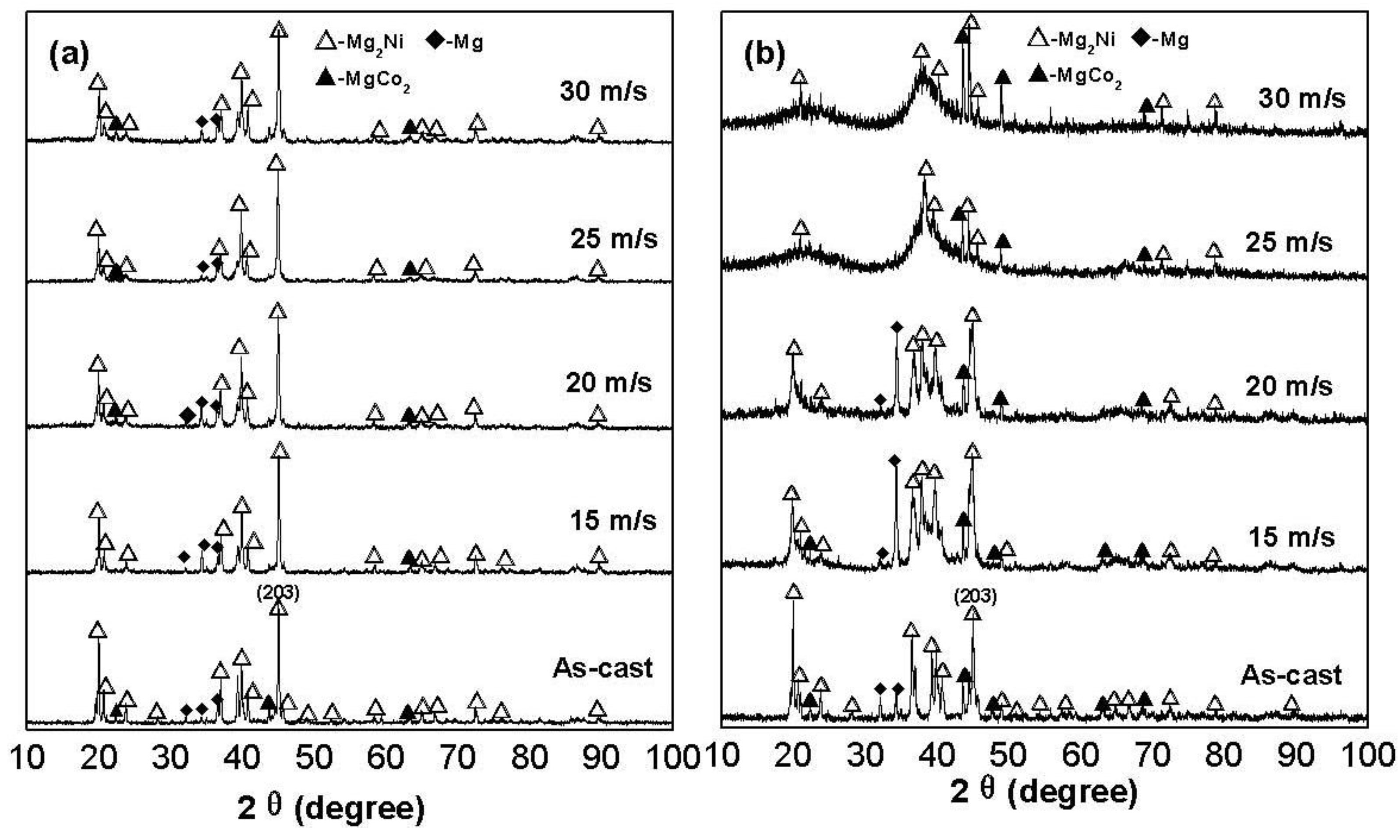
The X-ray diffraction (XRD) profiles of the as-cast and spun alloys are shown in
Figure 1. It reveals that the as-cast and spun Co
0.1 and Co
0.4 alloys have a multiphase structure, comprising of a major phase Mg
2Ni and secondary phases Mg and MgCo
2. The melt spinning treatment engenders an unapparent impact on the structure of the Co
0.1 alloy, while it causes a visible change of the structure of the Co
0.4 alloy. As the spinning rate reaches 25 m/s, the Co
0.4 alloy exhibits an obvious amorphous structure. Therefore, it may be surmised that the replacement of Ni by Co facilitates the glass formation in the Mg
2Ni-type alloy. Two possibilities may be considered as the reasons for the above result. Firstly, the addition of a third element to Mg-Ni or Mg-Cu alloys significantly facilitates the glass-formation [
16,
17]. Secondly, the glass forming ability of an alloy is closely related to the difference of the atomic radii in the alloy. The higher difference of the atomic radii enhances the glass forming ability [
18]. Therefore, the larger atomic radius of Co compared to that of Ni facilitates the glass-formation. Listed in
Table 1 are the lattice parameters, cell volumes and full width at half maximum (FWHM) values of the main diffraction peaks of the as-cast and spun Co
0.1 and Co
0.4 alloys, which were calculated by using Jade 6.0 software. It is clearly viewable from
Table 1 that the melt spinning causes a notably increase in the FWHM values of the main diffraction peaks of the alloys, which is doubtlessly attributed to the refined grains and the stored strain in the grains originated by the melt spinning. It is derived in
Table 1 that the increase of the Co content induces not only a visible increase in the FWHM values of the main diffraction peaks of the as-spun alloys but also an evident enlargement in the lattice parameters and cell volume of the alloys, to be attributed to the larger atomic radius of Co than Ni. Based on the FWHM values of the broad diffraction peak (203) in
Figure 1, the grain sizes <
Dhkl> (nm) of the as-cast and spun Co
0.1 and Co
0.4 alloys are calculated using Scherrer’s equation, also listed in
Table 1. The grain sizes of the as-spun alloys are in a range of 16 to 45 nm, basically consistent with results reported by Friedlmeier
et al. [
19].
Figure 1.
XRD profiles of the as-cast and spun alloys: (a) Co0.1 alloy; (b) Co0.4 alloy.
Figure 1.
XRD profiles of the as-cast and spun alloys: (a) Co0.1 alloy; (b) Co0.4 alloy.
Table 1.
Lattice parameters, cell volumes, full width at half maximum (FWHM) values and grain sizes of the as-cast and spun Co0.1 and Co0.4 alloys.
Table 1.
Lattice parameters, cell volumes, full width at half maximum (FWHM) values and grain sizes of the as-cast and spun Co0.1 and Co0.4 alloys.
| Quenching rate (m/s) | FWHM values | Grain sizes | Lattice parameters and cell Volume |
|---|
| 2θ (45.14°) | D203 (nm) | a (nm) | c (nm) | V (nm3) |
|---|
| Co0.1 | Co0.4 | Co0.1 | Co0.4 | Co0.1 | Co0.4 | Co0.1 | Co0.4 | Co0.1 | Co0.4 |
|---|
| 0 | 0.118 | 0.150 | 72 | 57 | 0.5210 | 0.5220 | 1.3244 | 1.3312 | 0.3113 | 0.3142 |
| 15 | 0.191 | 0.449 | 45 | 19 | 0.5210 | 0.5224 | 1.3251 | 1.3318 | 0.3115 | 0.3148 |
| 20 | 0.287 | 0.548 | 30 | 16 | 0.5210 | 0.5226 | 1.3258 | 1.3320 | 0.3117 | 0.3150 |
| 25 | 0.310 | — | 27 | — | 0.5211 | — | 1.3265 | — | 0.3118 | — |
| 30 | 0.408 | — | 21 | — | 0.5211 | — | 1.3287 | — | 0.3124 | — |
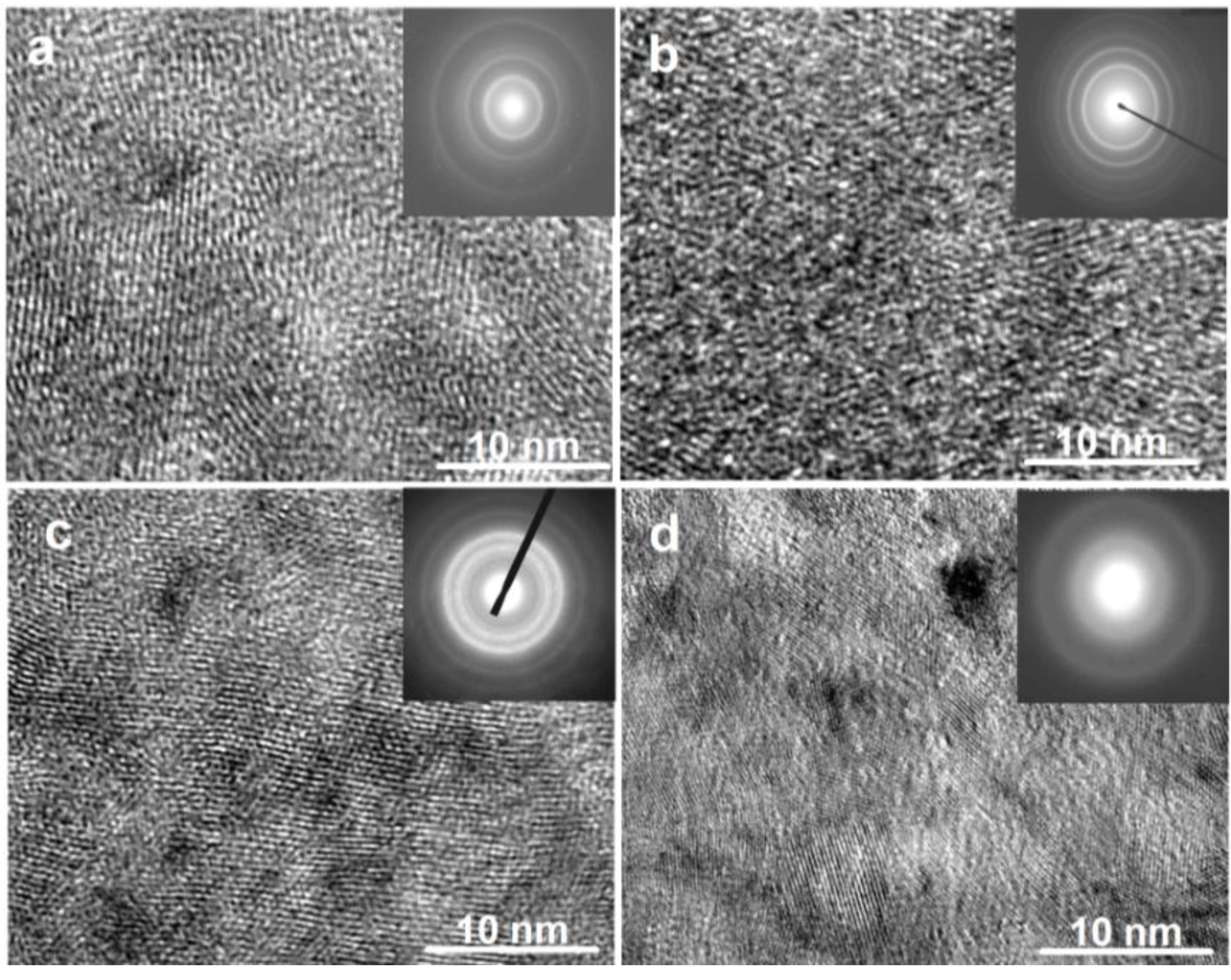
The TEM micrographs and electron diffraction (ED) patterns of the as-spun Co
0.1 and Co
0.4 alloys are shown in
Figure 2. It is seen that the as-spun (15 m/s and 30 m/s) Co
0.1 alloy displays a complete nanocrystalline structure, and its ED pattern appears as sharp multi-haloes, corresponding to a crystalline structure. The as-spun (15 m/s) Co
0.4 alloy also exhibits a nanocrystalline structure, but when the spinning rate reaches 30 m/s, an amorphous phase is clearly visible in the as-spun Co
0.4 alloy. Its electron diffraction pattern consists of broad and dull halo, confirming the presence of an amorphous structure, which agrees very well with the XRD observation shown in
Figure 1.
Figure 2.
High resolution transmission electron microscope (HRTEM) micrographs and electron diffraction (ED) patterns of the as-spun alloys: (a) as-spun (15 m/s) Co0.1 alloy; (b) as-spun (30 m/s) Co0.1 alloy; (c) as-spun (15 m/s) Co0.4 alloy; (d) As-spun (30 m/s) Co0.4 alloy.
Figure 2.
High resolution transmission electron microscope (HRTEM) micrographs and electron diffraction (ED) patterns of the as-spun alloys: (a) as-spun (15 m/s) Co0.1 alloy; (b) as-spun (30 m/s) Co0.1 alloy; (c) as-spun (15 m/s) Co0.4 alloy; (d) As-spun (30 m/s) Co0.4 alloy.
2.3. Hydriding and Dehydriding Kinetics
The hydrogen absorption was carried out under 1.5 MPa hydrogen pressure (in fact, this is the initial pressure of hydriding process) at 200 °C, and hydrogen desorption at a pressure of 1 × 10⁻⁴ MPa at 200 °C.
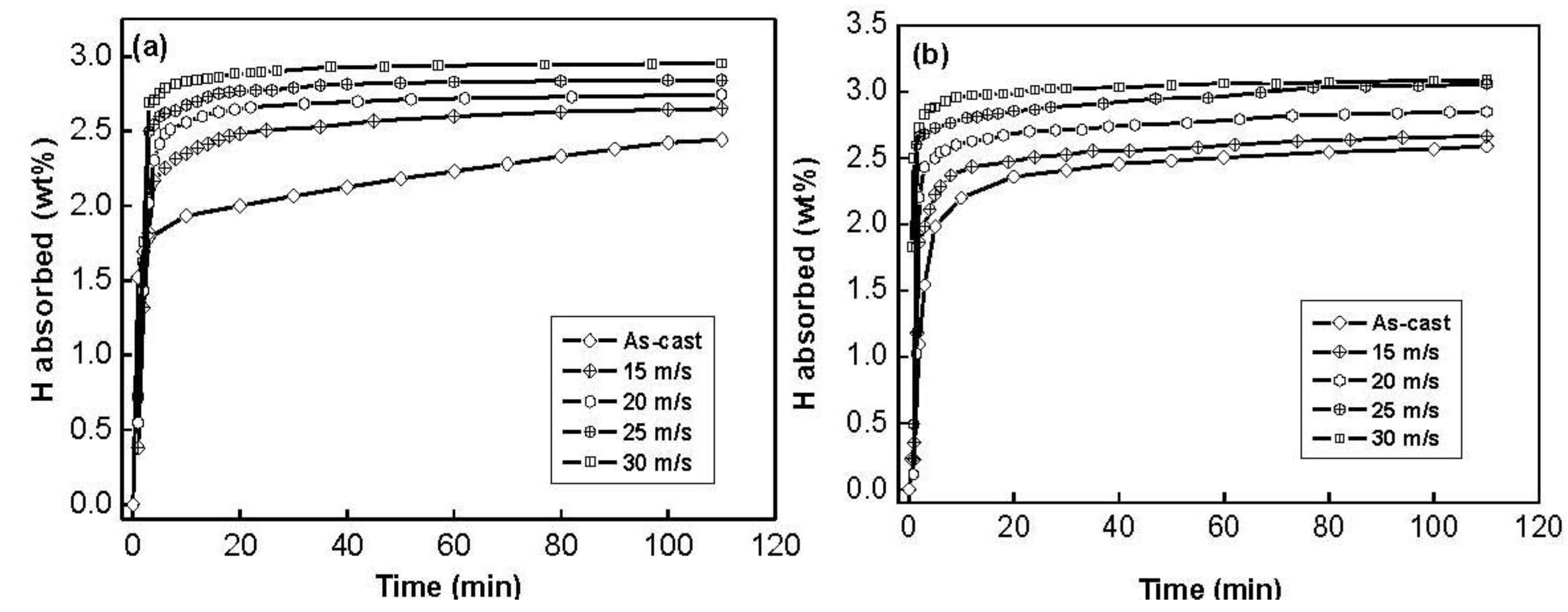
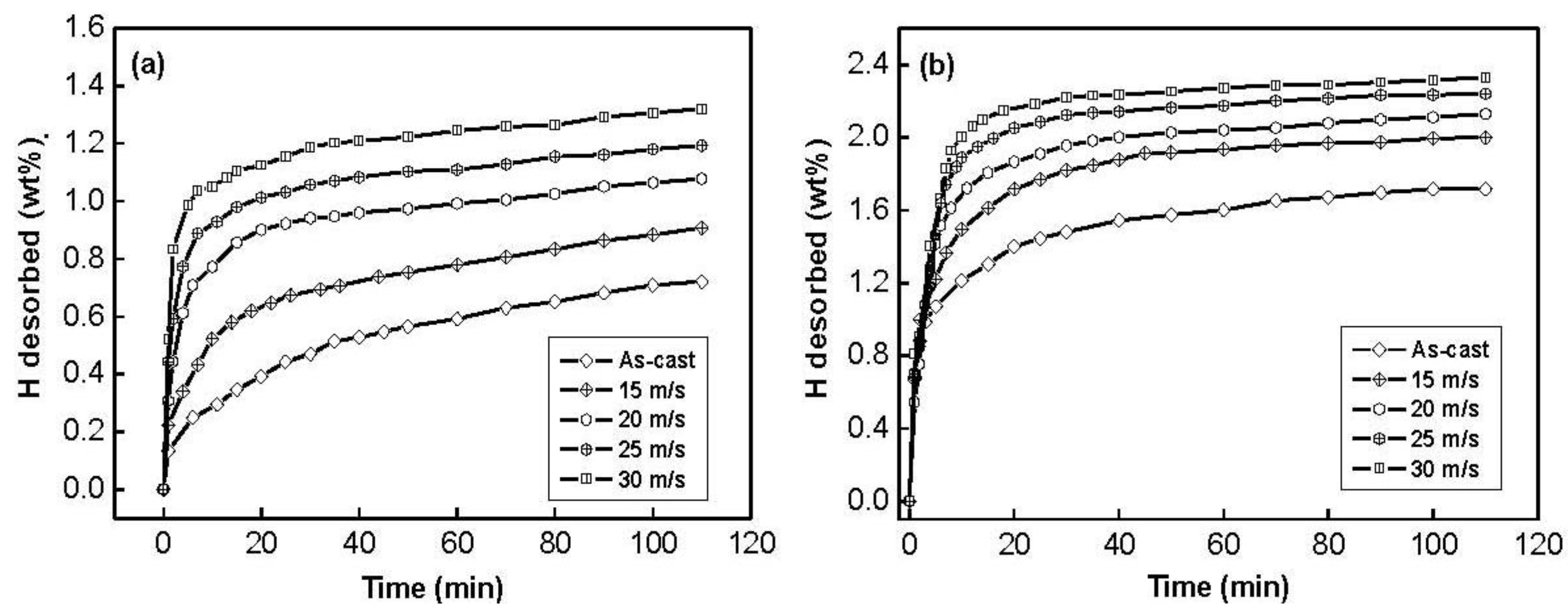
The hydrogen absorption kinetic curves of the as-cast and spun Co
0.1 and Co
0.4 alloys are depicted in
Figure 4. It is quite evident that the hydrogen absorption capacity and kinetics of all the as-spun nanocrystalline Mg
2Ni-type alloys studied are superior to those of the as-cast ones. It can be seen in
Figure 4 that the hydrogen absorption kinetics of the as-spun alloys is extremely fast so that the alloys absorb more than 85% of their hydrogen capacities within the first 5 min.
Figure 4.
Hydrogen absorption kinetic curves of the as-cast and spun alloys: (a) Co0.1 alloy; (b) Co0.4 alloy.
Figure 4.
Hydrogen absorption kinetic curves of the as-cast and spun alloys: (a) Co0.1 alloy; (b) Co0.4 alloy.
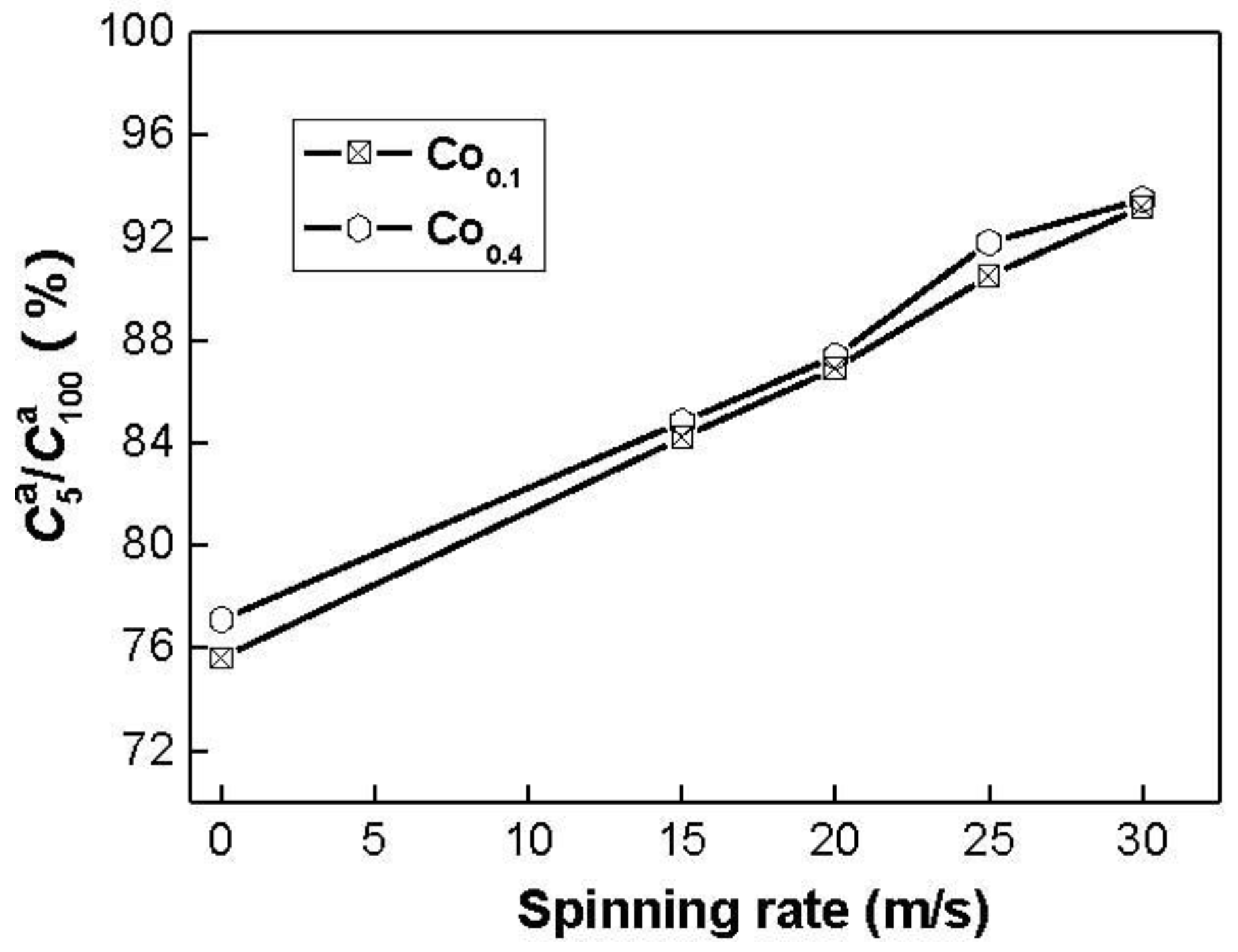
The hydrogen absorption kinetics of the alloy is signified by hydriding saturation ratio (
), being defined as
, where
and
are hydrogen absorption capacities in the times of 100 min and
t min, respectively. Apparently, for a fixed time
t, a larger saturation ratio
means better hydrogen absorption kinetics. It is reasonable to take the
value as the saturated hydrogen absorption capacity of the alloy because the experimental result indicates that the
value is more than 95% of the saturated hydrogen absorption capacity for all the alloys. The hydrogen absorption saturation ratio (
) (
t = 5) of the alloys as a function of the spinning rate is presented in
Figure 5.
Figure 5.
Evolution of the hydrogen absorption saturation ratio () of the alloys with the spinning rate.
Figure 5.
Evolution of the hydrogen absorption saturation ratio () of the alloys with the spinning rate.
The figure reveals that the
values of the alloys notably increase with rising spinning rate. With an increase in the spinning rate from 0 (as-casts is defined as spinning rate of 0 m/s) to 30 m/s, the
value increases from 75.6 to 93.2% for the Co
0.1 alloy. This variable behavior may be ascribed to the structural change caused by the melt spinning. The improved hydrogen absorption kinetics can be explained with the enhanced hydrogen diffusivity in the amorphous and nanocrystalline microstructures as the amorphous phase around the nanocrystalline leads to an easier access of hydrogen to the nanograins, avoiding the long-range diffusion of hydrogen through an already formed hydride, which is often the slowest stage of absorption. Upon refining the microstructure, a lot of new crystallites and grain boundaries evolve, which may act as fast diffusion paths for hydrogen absorption [
21].
In order to reveal the mechanism of the melt spinning improving hydrogen absorption kinetics of the alloy, it is evidently necessary to investigate the influences of the melt spinning on the H diffusion ability in the alloy. The H diffusion coefficients in the as-cast and spun alloys were measured using the potential step technique. A potential step of +500 mV
versus the stabilized open circuit potential of the fully charged electrode was applied and the decrease in discharge current was monitored as a function of time.
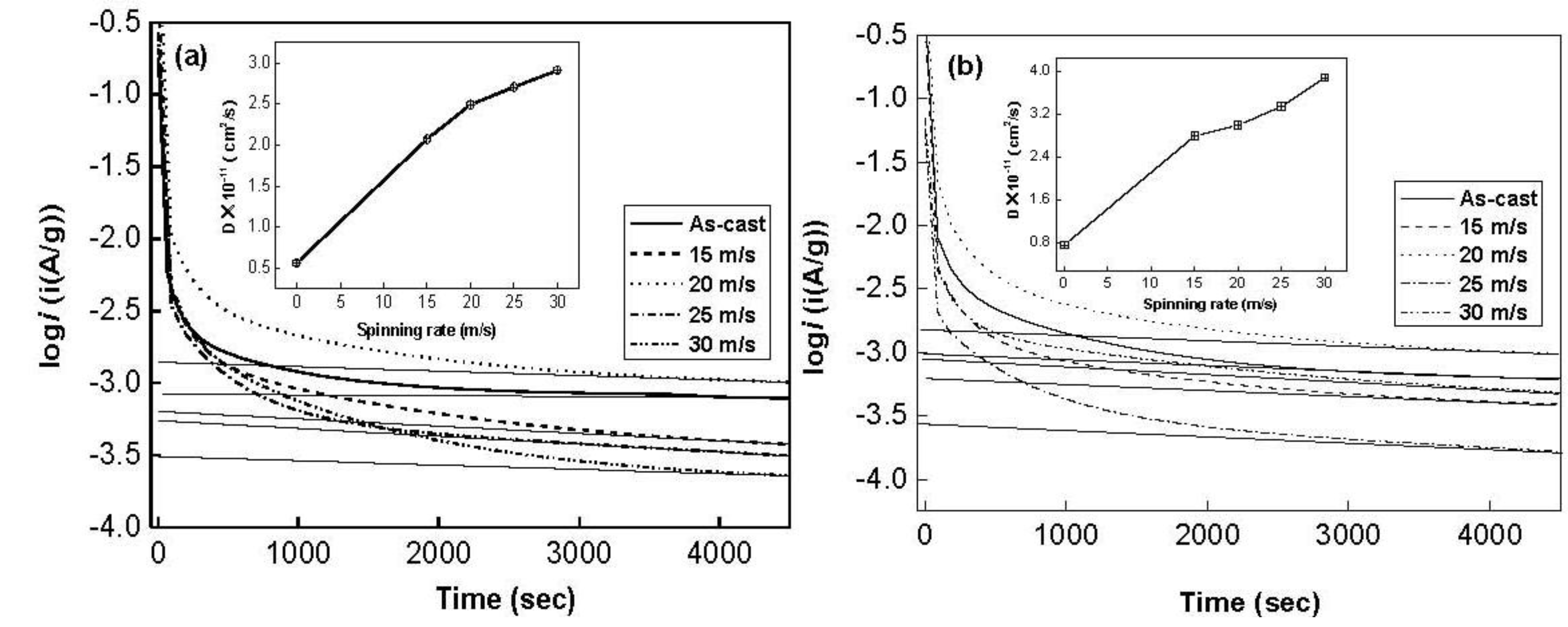
Figure 6 shows the semilogarithmic curves of anodic current
versus working duration of the Co
0.1 and Co
0.4 alloys. The diffusion coefficient
D of the hydrogen atoms in the bulk of the alloy can be calculated through the slope of the linear region of the corresponding plots according to following formulae [
22].
where
i is the diffusion current density (A/g),
D is the hydrogen diffusion coefficient (cm
2/s),
C0 is the initial hydrogen concentration in the bulk of the alloy (mol/cm
3),
Cs is the hydrogen concentration on the surface of the alloy particles (mol/cm
3),
a is the alloy particle radius (cm),
d is the density of the hydrogen storage alloy (g/cm
3),
t is the discharge time (s), respectively. In Equation (2),
is the slope of the linear region of the semilogarithmic curves of anodic current
versus working duration, which can easily be obtained by an origin 75 software.
a is the alloy particle radius, supposing
a = 15 μm. Thus, the hydrogen diffusion coefficient
D can easily be calculated. The
D values calculated by Equation (2) are also illustrated in
Figure 6. It indicates that an increase in the spinning rate turns out a growth in
D value. As the spinning rate rises from 0 to 30 m/s, the D value increases from 5.62 × 10
−12 to 2.91 × 10
−11 cm
2/s for the Co
0.1 alloy, and from 7.49 × 10
−12 to 3.88 × 10
−11 cm
2/s for Co
0.4 alloy, which conforms very well to the result obtained by Niu
et al. [
23]. The benefaction of the melt spinning on the hydrogen absorption kinetics of the alloy is attributed to the increased cell volume and the refined grain caused by the melt spinning since the grain boundary possesses the largest hydrogen absorption capacity [
24]. The above-mentioned results clarify that H diffusion ability in the alloy is a crucial factor of the hydrogen absorption kinetics of the alloy. Spassov
et al. [
25] also confirmed that the melt spinning could significantly improve the hydrogen absorption performance of Mg-based alloy, and obtains the maximum hydrogen capacity of 4.0 wt % H for the as-spun Mg
75Ni
20Mm
5 (Mm = Ce, La-rich mischmetal) alloy.
Figure 6.
Semilogarithmic curves of anodic current vs. time responses of the alloys: (a) Co0.1 alloy; (b) Co0.4 alloy.
Figure 6.
Semilogarithmic curves of anodic current vs. time responses of the alloys: (a) Co0.1 alloy; (b) Co0.4 alloy.
The hydrogen desorption kinetic curves of the as-cast and spun Co
0.1 and Co
0.4 alloys are exhibited in
Figure 7. The hydrogen desorption process of the Co
0.1 and Co
0.4 alloys displays an evident feature, very fast initial hydrogen desorption, followed by a slack increase in the amount of hydrogen desorbed.
Figure 7.
Hydrogen desorption kinetic curves of the alloys: (a) Co0.1 alloy; (b) Co0.4 alloy.
Figure 7.
Hydrogen desorption kinetic curves of the alloys: (a) Co0.1 alloy; (b) Co0.4 alloy.
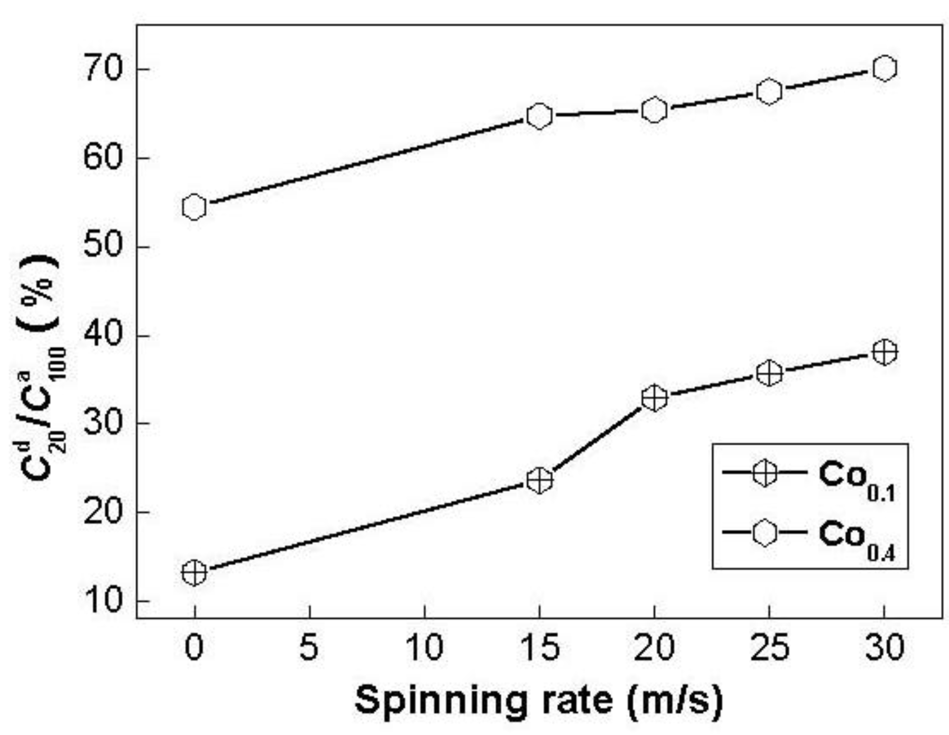
Similarly, the hydrogen desorption kinetics of the alloy is indicated by hydrogen desorption ratio (
), being defined as
, where
is the hydrogen absorption capacity in 100 min and
is the hydrogen desorption capacity in the time of
t min, respectively. The spinning rate dependence of the hydrogen desorption ratio (
) (
t = 20) of the Co
0.1 and Co
0.4 alloys is illustrated in
Figure 8. It can be seen in
Figure 8 that the melt spinning treatment remarkably enhances the
values of the alloys, suggesting that melt spinning facilitates hydrogen desorption of Mg
2Ni-type alloy. With the increase in the spinning rate from 0 to 30 m/s, the
value increases from 13.2 to 38.1% for the Co
0.1 alloy, and from 54.5 to 70.2% for the Co
0.4 alloy. The improved hydrogen desorption kinetics is mostly associated with the change of the structure of the alloy induced by the melt spinning. It is well known that when crystalline materials are spun, they become at least partially disordered.
Figure 8.
Evolution of the hydrogen desorption ratio () of the alloys with the spinning rate.
Figure 8.
Evolution of the hydrogen desorption ratio () of the alloys with the spinning rate.
At same time, some crystal defects such as dislocations, stacking faults and grain boundaries are introduced. As a result, a large amount of internal energy would be stored and would lead to non-stabilization of the lattice, yielding the nanocrystalline or even an amorphous phase. Niu
et al. [
23] clarified that the introduction of defects, disordering and internal strain gives rise to increasing hydriding/dehydriding rates and capacity. It was reported [
21] that the hydrogen absorbing and desorbing rates of Mg-based alloys were strongly enhanced by refinement of the grains. As noted, the internal strain increases with rising spinning rate. The higher the spinning rate, the more defects are introduced into the Mg
2Ni alloy. Furthermore, the grain size of the alloy notably decreases with increasing spinning rate. Hence, it is understandable that the hydrogen desorption ratio (
) of the alloy markedly increases with rising spinning rate. It is noteworthy that, for a fixed spinning rate, the
value of the Co
0.4 alloy is much larger than that of the Co
0.1 alloy, suggesting that increasing Co content facilitates hydrogen desorption. The increased hydrogen desorption kinetics by Co substitution is ascribed to two reasons. On the one hand, the substitution of Co for Ni notably intensifies the glass forming ability of Mg
2Ni-type alloy because amorphous Mg
2Ni shows an excellent hydrogen desorption capability. On the other hand, such substitution decreases the stability of the hydride and makes the desorption reaction easier [
26].
2.4. Electrochemical Hydrogen Storage Kinetics
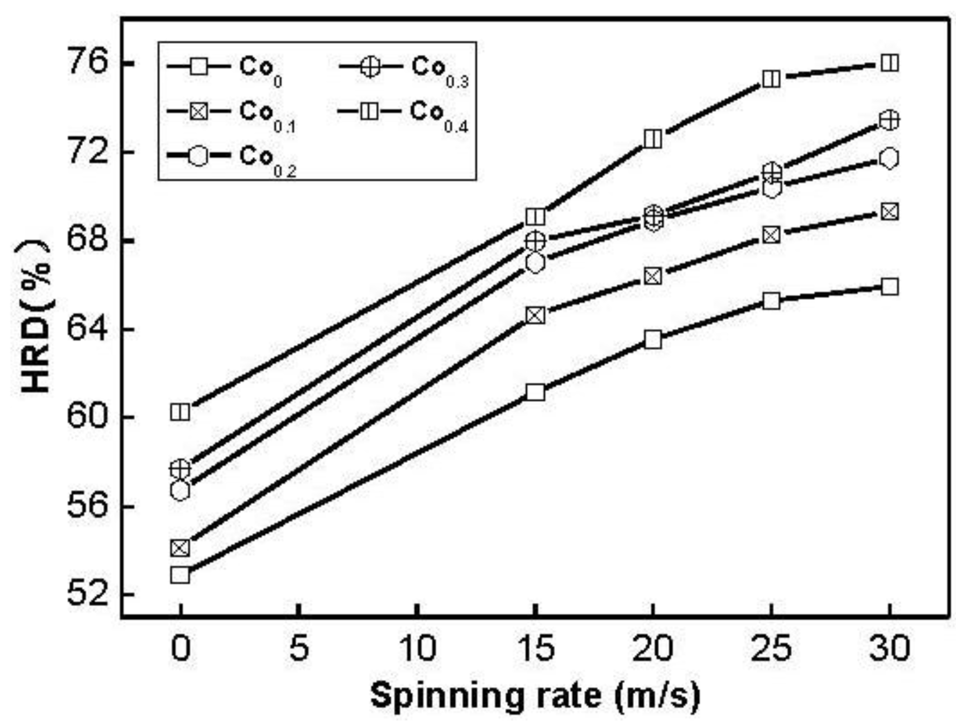
It is quite important to restrain rapid decrease of discharge capacity even at a high charge/discharge current density for the practical application of the hydride electrode in Ni–MH battery. The electrochemical hydrogen storage kinetics of the alloy is characterized by its high rate dischargeability (HRD), being calculated according to following formula: HRD = C
100,max/C
20,max × 100%, where C
100,max and C
20,max are the maximum discharge capacities of the alloy electrode charged–discharged at the current densities of 100 and 20 mA/g, respectively. The HRD values of the alloys as a function of spinning rate are exhibited in
Figure 9. It is evident that the HRD values of all the alloys increase with increasing spinning rate. As the spinning rate increases from 0 to 30 m/s, the HRD value rises from 54.2 to 69.3% for the Co
0.1 alloy, and from 60.3 to 76.0% for the Co
0.4 alloy. High rate discharge ability (HRD) is a kinetic performance of hydrogen absorbing/desorbing of the alloy electrode, basically depending on the charge transfer at the alloy-electrolyte interface the hydrogen diffusion process from the interior of the bulk to the surface of alloy particle [
27]. The melt spinning treatment visibly enhances the HRD values of the alloys, to be attributed to a positive action of the melt spinning on the hydrogen diffusion in the alloy as shown in
Figure 6.
Figure 9.
Evolution of the high rate discharge ability (HRD) of the alloys with the spinning rate.
Figure 9.
Evolution of the high rate discharge ability (HRD) of the alloys with the spinning rate.
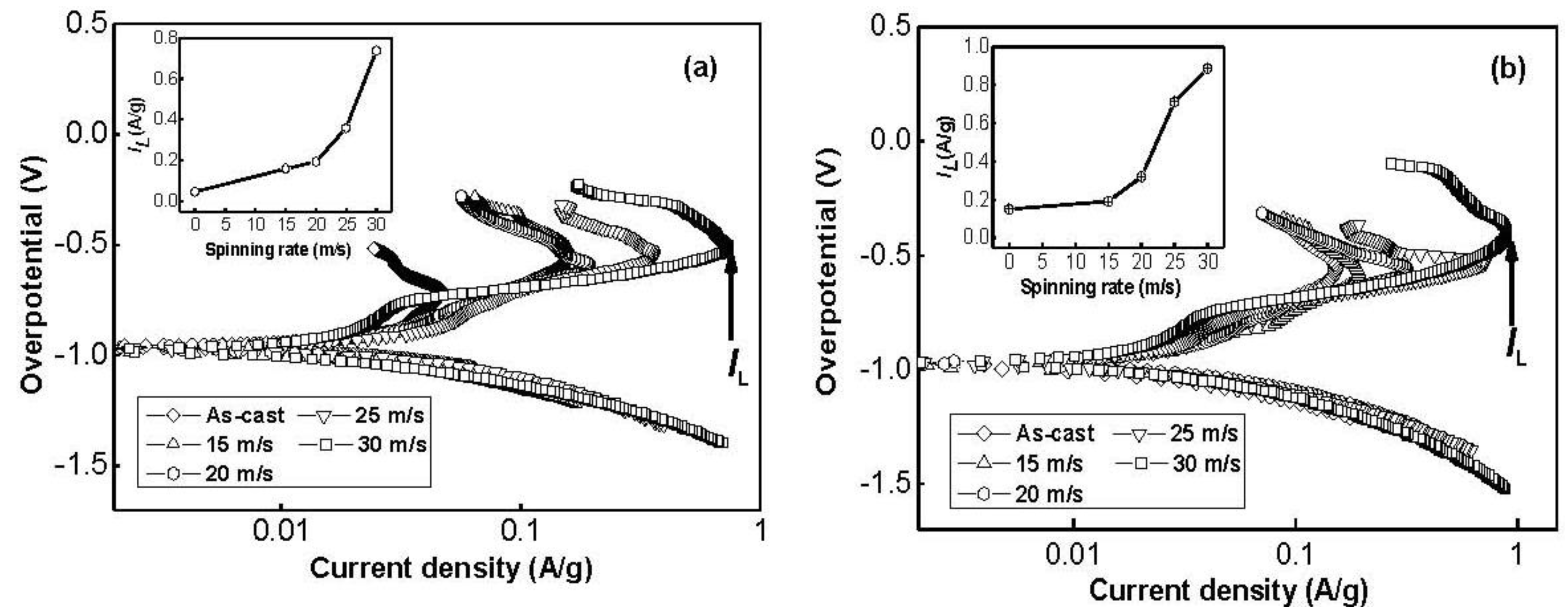
To determine the kinetics of hydrogen absorption/desorption, Tafel polarization measurements were carried out on the experimental alloy electrodes.
Figure 10 depicts the Tafel polarization curves of the as-cast and spun Co
0.1 and Co
0.4 alloy electrodes at the 50% depth of discharge (DOD). It is quite evident that, in all cases, the anodic current densities increase to a limiting value, then decrease. The existence of a limiting current density,
IL, indicates that an oxidation reaction took place on the surface of the alloy electrode, and the generated oxidation product resists further penetration of hydrogen atoms [
28]. The decrease of the anodic charge current density on cycling implies that charging is becoming more difficult. Thus, the limiting current density,
IL, can be seen as the critical passivation current density. It is viewable in
Figure 10 that
IL values of the alloys notably increase with rising spinning rate. With an increase in the spinning rate from 0 to 30 m/s,
IL value increases from 46.7 to 737.3 mA/g for the Co
0.1 alloy, and from 150.9 to 887.4 mA/g for the Co
0.4 alloy. Ratnakumar
et al. [
29] and Liu
et al. [
30] presumed that the limiting current can be related to and is mainly controlled by the solid state diffusion of hydrogen in metal-hydride electrodes. Hence, the positive impact of the melt spinning on the
IL value can be ascribed to the change of the structure of the alloy induced by the melt spinning. Furthermore,
Figure 10 displays an interesting phenomenon that the corresponding peak potential of the limiting current apparently shifts to positive direction with increasing spinning rate, indicating an enhanced excellent ability of antioxidation or anticorrosion by the melt spinning.
Figure 10.
Tafel polarization curves of the as-cast and spun alloy electrodes at the 50% depth of discharge (DOD): (a) Co0.1 alloy; (b) Co0.4 alloy.
Figure 10.
Tafel polarization curves of the as-cast and spun alloy electrodes at the 50% depth of discharge (DOD): (a) Co0.1 alloy; (b) Co0.4 alloy.
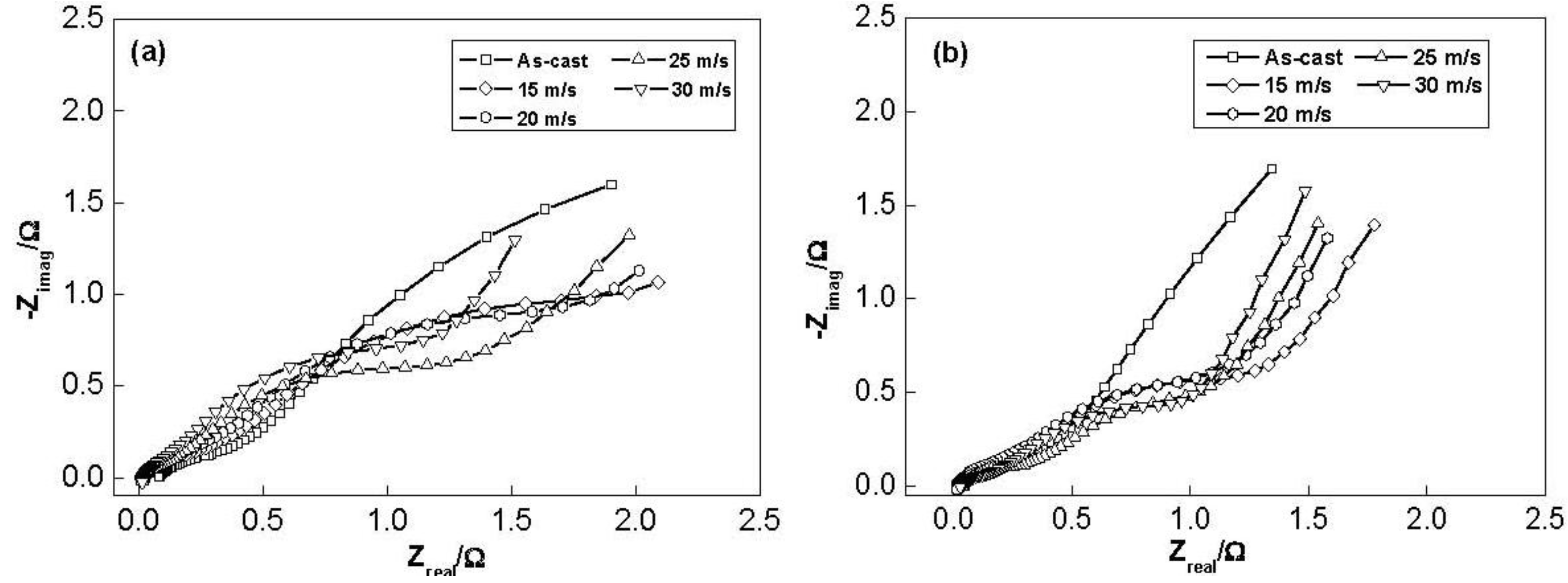
The electrochemical impedance spectra (EIS) of the as-cast and spun Co
0.1 and Co
0.4 alloy electrodes at 50% DOD are shown in
Figure 11. It is viewable that each EIS spectrum contains two semicircles followed by a straight line. Kuriyama
et al. [
31] considered that the smaller semicircle in the high frequency region is attributed to the contact resistance between the alloy powder and the conductive material, while the larger semicircle in the low frequency region is attributed to the charge-transfer resistance on the alloy surface. The linear response at low frequencies is indicative of hydrogen diffusion in the bulk alloy. Hence, the electrode kinetics of the as-cast and spun alloys are dominated a mixed rate-determining process. It can be seen in
Figure 11 that the radius of the large semicircle in the low frequency for the Co
0.1 and Co
0.4 alloy clearly decreases with increasing spinning rate, implying that the refined grain by the melt spinning facilitates charge-transfer of the alloy electrode. Based on the above mentioned results, it can be concluded that a suitable microstructure is quite crucial to obtain the excellent hydrogen storage kinetics of the Mg
2Ni-type alloy.
Figure 11.
Electrochemical impedance spectra (EIS) of the alloy electrodes at the 50% depth of discharge (DOD): (a) Co0.1 alloy; (b) Co0.4 alloy.
Figure 11.
Electrochemical impedance spectra (EIS) of the alloy electrodes at the 50% depth of discharge (DOD): (a) Co0.1 alloy; (b) Co0.4 alloy.

