2. Results and Discussion
To achieve an accelerated cooling process, crushed ice was employed to control the temperature change. As shown in
Table 1, four typical accelerated cooling processes named with Process-I, -II, -III and -IV were introduced by the addition of 4, 10, 25 and 50 g of ice, respectively. After addition of crushed ice to the hot LPEI solution, the temperature of the mixture decreased quickly in a short time. For Process-I, the temperature decreased rapidly from 85 °C to about 39 °C in 1 min and then slowly decreased to room temperature; for Process-II, it reached the lowest temperature of about 12 °C in 1 min; for Process -III and -IV, it decreased the lowest temperature of 1 °C in 1 min.
Table 1.
Temperature changes after addition of crushed ice.
Table 1.
Temperature changes after addition of crushed ice.
| | Process-I | Process-II | Process-III | Process-IV |
|---|
![Materials 05 01787 i001]() |
| linear polyethyleneimine (LPEI) wt % (Amount) | 2, 5, 10
(10 g) | 2, 5, 10
(10 g) | 2, 5, 10
(10 g) | 2
(10 g) |
| Amount of ice added (g) | 4 | 10 | 25 | 50 |
| The lowest temperature after addition of ice | 39 °C | 12 °C | 1 °C | 1 °C |
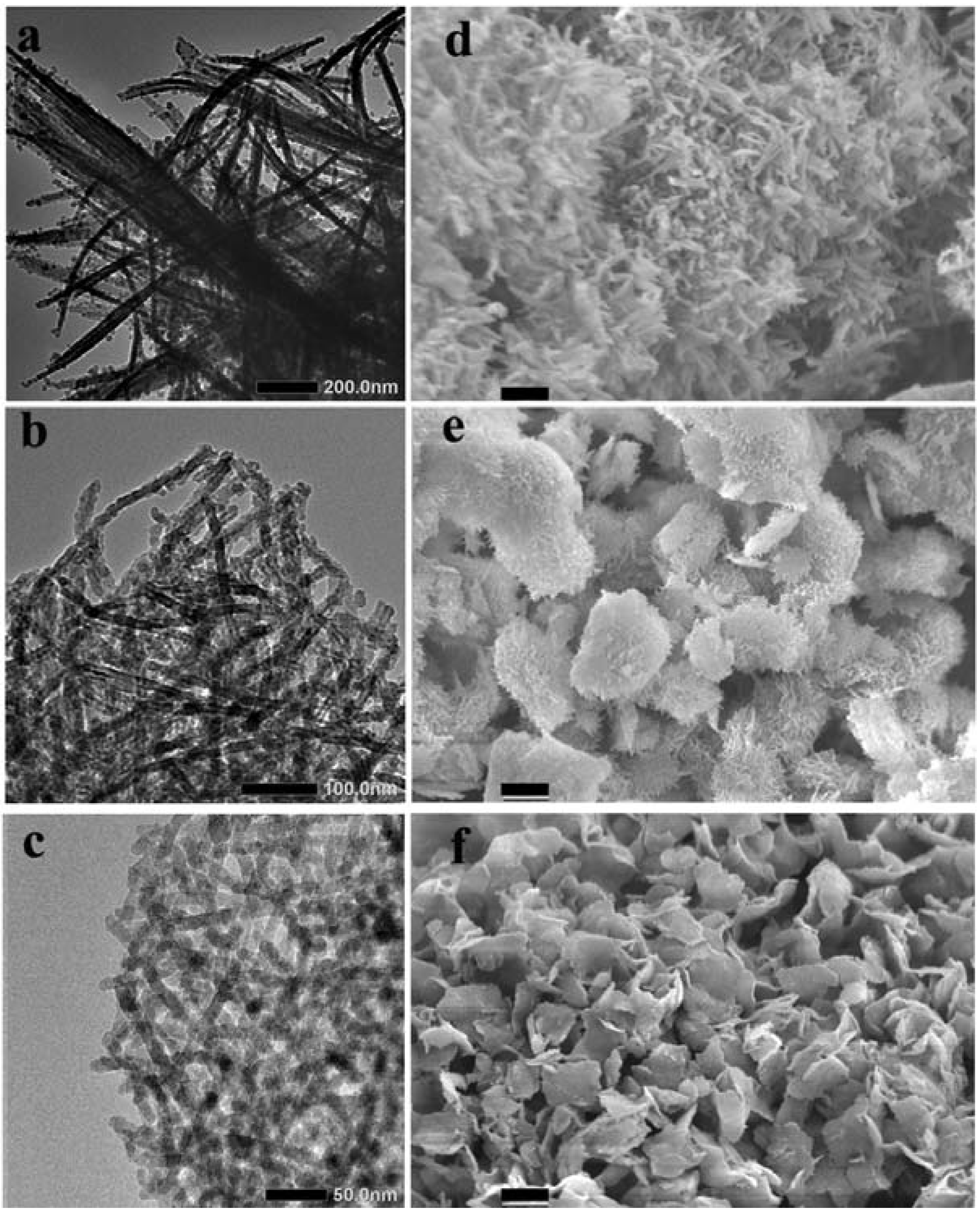
Our first interest here is screening whether the crystalline LPEI aggregates generated by the differently accelerated cooling processes afford the specially structured silica after mixing the LPEI aggregates with MS-51 (methyl silicate-51, a commercially available silica source with 5-mer tetramethoxysilane). Therefore, we subjected the silica powders obtained from Process-I, -II and -III to TEM and SEM observation. Interestingly, as seen in the in
Figure 1, the products of LPEI@SiO
2 via different cooling processes showed different morphologies and sizes. In the case of Process-I, the produced LPEI@SiO
2 appeared larger bundles in which a lot of one-dimensional nano structures (ribbon-like fibrils) coalesced each other. This is likely the case of natural cooling hot LPEI solution to room temperature in our previous reports [
15]. Under the dramatically accelerated cooling conditions, however, the produced LPEI@SiO
2 turned into the forms of nanotube-based platelets (in Process-II) and nanowires-based platelets (in Process-III). The size of the platelets in Process-II ranged from 5 to 10 µm but became small, below 5 µm, in Process-III. Interestingly, a lot of nanotubes with approximately 20 nm in diameter or nanowires approximately 10 nm in diameter knitted closely and densely each other forming platelets in which the nanotubes or nanowires grew nearly straightly towards the edge of platelets without embedding the ends in the platelets body. The nanotubes are approximately 3 nm hollow inside. In contrast, the silica mediated by the process-IV showed irregular fibrils-based bundles in which the fibrils are likely assemblies of irregular nanoparticles with an average size of 15 nm,
i.e., necklace-like structure (see
Figure S1 in the Supporting Information). Therefore, it is conclusive that the morphologies and the fine structures of the 1D LPEI@SiO
2 hybrids are easily controllable through different cooling processes.
Figure 1.
The transmission electron microscope (TEM) (left column) and scanning electron microscope (SEM) (right column) images of LPEI@SiO2 obtained under different cooling processes by fixing 10 g of 2 wt % LPEI and 10 mL of 10 vol % MS-51. From up row to bottom one, mice increased from 4, to 10, to 25 g, and corresponded to Process-I, -II, -III, respectively. Scale bars: (d), 1 μm; (e)–(f), 2.5 μm. Where LPEI was linear polyethyleneimine, MS-51 was methyl silicate-51.
Here, we can see a tendency towards the differences of 1D LPEI@SiO
2 in nano-structure correlating to the morphologies variance in the micro-scale. This is attributed to the growth of the LPEI crystallites. In the previously mentioned three cooling process I-III, the final concentration of the LPEI and the lowest temperature after addition of ice decreased with increasing the amount of ice added. Despite an effect of quickly lowering temperature from above 85 °C to below 40 °C in Process-I, this quenching method did not affect to change the resulted silica structure compared to naturally cooling method in the conditions of the same concentration of LPEI. As seen in
Figure 1d, the LPEI@SiO
2 hybrids obtained in Process-I were mainly composed of bundles of fibers with diameters of several hundred nanometers and length of several micrometers. In our previous work, it was confirmed that the concentrations ranging 0.5~5 wt % LPEI resulted in the same ribbon-like fibrous silica bundles in the naturally cooling conditions [
15]. Both in the Process-II and -III, the resulted silica powders have platelet-like morphologies, which are transcribed from LPEI precursors. This indicates that the suddenly quenched temperature arriving below 12 °C within 1 min is effective to change the growing direction of LPEI crystallites from bundles to platelets in which a lot of crystalline wires of LPEI crossly overlapped each other to form mat-like plates.
Since this biomimetic silicification included the pre-assembly of crystalline LPEI and post-deposition of silica, the amounts of LPEI and MS-51 may also impose control on the surface areas, porosity and compositions. Taking the Process-II as an example, we examined the silica deposition by changing the concentrations of LPEI and MS-51. In the TG-DTA analysis of the hybrids (see
Figure S4 of TG-DTA charts), two endothermic peaks around 230–250 °C and 360–380 °C are observed, which can be attributed to the decompositions of LPEI. The mass ratios of silica/LPEI calculated based on the mass loss around 150~800 °C were listed in
Table 2. It is evident that the LPEI@SiO
2 hybrids resulted from higher concentrations of LPEI possess lower content of silica while the hybrids given upon higher concentrations of MS-51 trend to deposit plenty of silica.
Table 2.
Composition of LPEI@SiO2 hybrids obtained from different conditions.
Table 2.
Composition of LPEI@SiO2 hybrids obtained from different conditions.
| | MS-51(in vol %) |
| 10% | 20% | 30% |
| SiO2/LPEI | SiO2/LPEI | SiO2/LPEI |
| LPEI concentration (wt %) | 2 | 77/23 | 82/18 | 81/19 |
| 5 | 62/38 | 73/27 | 75/25 |
| 10 | 54/46 | 65/35 | 68/32 |
We calcined the LPEI@SiO
2 hybrids at 800 °C and subjected the remained silica powders to N
2 adsorption-desorption measurement to understand the characteristics in surface area and pore size distributions. It was found that the typical N
2 adsorption-desorption isotherms for the calcined silica showed characteristic hysteresis loops as seen in porous materials and the pore size distribution ranged between approximately 5–30 nm (
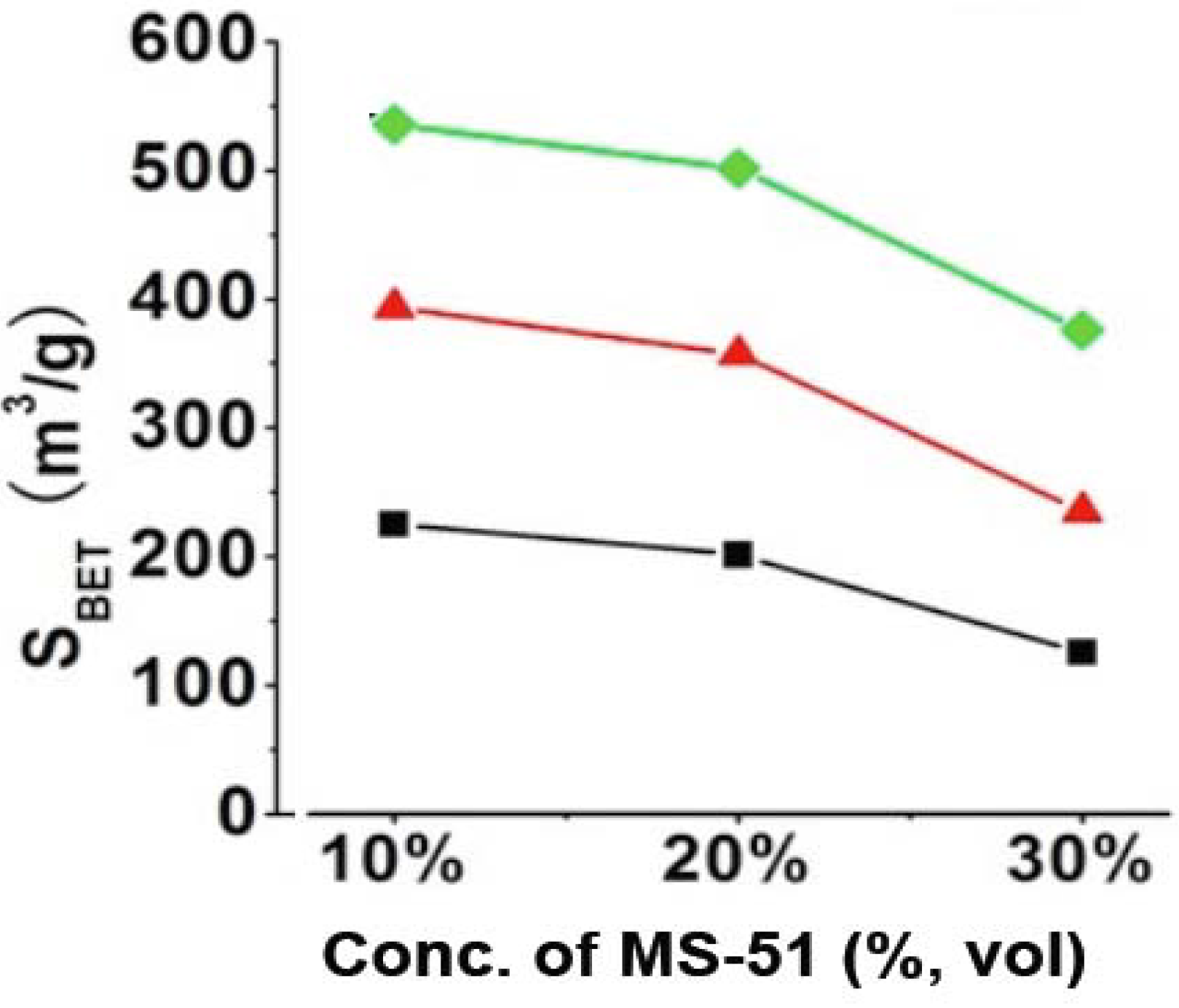
Figure S3). Such mesoporosity would be caused by the hollow structure of silica nanotube and the intergrain voids, which are constructed in the platelet piled up by a lot of 1D-structured nanosilica. It was found that the mesoporosity became smaller for the silica that was prepared under high concentrations of MS-51. Practically, the BET surface areas (S
BET) largely related with the concentrations of LPEI (wt %) and MS-51 (vol %), which can be clarified in
Figure 2. It is apparent that the values of S
BET for the silica elevated with increasing LPEI concentrations while declined with increasing MS-51 concentrations (
Figure 2). Herein, the values of S
BET can be divided into three ranges based on LPEI concentrations: 100–200 m
2/g for LPEI being 2.0%, 250–350 m
2/g for 5.0% and 350–500 m
2/g for 10% (in weight). Obviously, the higher concentration of LPEI was used, the larger surface area of silica was produced. This means that the LPEI enclosed in silica can play as a pore-directing agent; the more LPEI the more pores. On the other hand, S
BET decreased about 100 m
2/g when concentration of MS-51 changed from 10% to 30% (in vol %), indicating that the relatively less amount of MS-51 are favorable to increase surface area of the silica. This is consistent with the increment of mesoporosity under lower concentration of MS-51. We confirmed that the SiO
2 calcined at 800 °C, did not show morphological damage.
Figure 2.
BET surface areas of SiO2 obtained by removing LPEI. Black line: 2% LPEI; Red line: 5% LPEI; Green line: 10% LPEI.
Figure 2.
BET surface areas of SiO2 obtained by removing LPEI. Black line: 2% LPEI; Red line: 5% LPEI; Green line: 10% LPEI.
As pointed out by the results above, the 1D structure-based silica could be successfully modulated by the simple sudden cooling of the hot LPEI solution. The following issues are more about the details of the silicification process ranging from crystallization and assembly of LPEI to surface deposition of silica. Considering that the cooling was in fact a process of precipitation accompanying crystallization and rearrangement of LPEI chains, the nucleation and growth were hence interfered by the temperature change. For example, in Process-III with a strongly accelerated cooling process, the temperature suddenly reached 1 °C. This would cause a decrease of dissolved LPEI molecules in the solutions since LPEI is not soluble in water at ambient temperature condition. Because the formation of crystalline LPEI depends on the dissolved LPEI chains, which diffuse toward the as-formed nuclei, the growth and extension of the crystallites were then suppressed in this too quick cooling process. Consequently, the crystallization proceeded more rapidly with disordered fractions, compared with the long-range diffusion, and the nuclei were abundantly formed in a short time. In addition, in this case a part of LPEI molecules, which are independent of whether the thermodynamically most favored configuration is achieved, reached on the crystal surface and were incorporated into the crystal with amorphous state. As a result, short LPEI nano-wires with loose and irregular arrangements of LPEI chains were formed. This loose state allowed the permeation of silica source into the cores of LPEI nano-wires, leading to the formation of LPEI@SiO
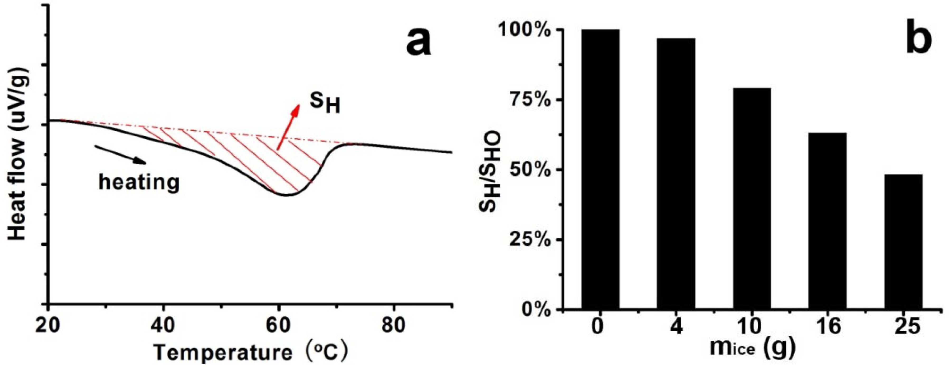
2 with solid appearance seen in TEM images. In Process II with an adequate cooling process, on the contrary, the crystallization proceeded more slowly compared with diffusion and the growth and rearrangement were supported, resulting in nano-fibers with rigid and regular arrangement of LPEI chains. This rigid structure is capable of blocking the permeation of silica source into the cores. In consequence, silica was mainly deposited on the surfaces to form silica shell. In this case, the TEM image just appeared as a tubular hollow structure. To some extent, the DSC data may further confirm the viewpoints above. The LPEI aggregates obtained via different cooling process were used for DSC analysis, and the typical heating curve was displayed in
Figure 3a. The integrated heat of fusion (denoted as S
H) on the heating curve was employed to judge the crystallinity [
25,
26]. By plotting the ratios of S
H/S
HO against
mice (where S
H is based the samples obtained under the conditions in the presence of ice and S
HO in the absence of ice), we compared the crystallinity of the LPEI aggregates. As seen in
Figure 3b, the ratios declined with the increase of
mice, meaning that the crystallinity decreased. If the LPEI chains arranged irregularly and the crystalline LPEI backbone was short, less energy is needed for the melting of crystalline LPEI and the ratio of S
H/S
HO would be estimated to be low. The ratio of S
H/S
HO in Process-I (
mice = 4 g) was about 97%, which indicates that our cooling process is near that in a natural cooling one. Indeed, the fibrous morphologies in the SEM are quite similar to our previous reports. But with increasing the ice amount (
i.e., decrease of S
H/S
HO), the evident morphological changes in the resulted silica happened. Although the detailed and complex assembly processes of crystalline LPEI are not clear, from the resulted silica structure, we can expect that in the accelerated cooling process the short and individual crystalline nano-wires of LPEI were geometrically favorable to link and knit each other growing to be the platelet-like or film-like morphologies. However, within the non-accelerated cooling system, the formed long nano-fibers of LPEI became difficult to assembly on a planar film, and finally presented as fibrous bundles as seen in SEM image.
Figure 3.
Differential scanning calorimetry (DSC) curve and integrated heat of fusion (SH) of samples under different cooling processes (different mice) by fixing 5% LPEI. (a) Typical DSC curve; (b) Plot of ratios of SH/SHO against mice.
Figure 3.
Differential scanning calorimetry (DSC) curve and integrated heat of fusion (SH) of samples under different cooling processes (different mice) by fixing 5% LPEI. (a) Typical DSC curve; (b) Plot of ratios of SH/SHO against mice.
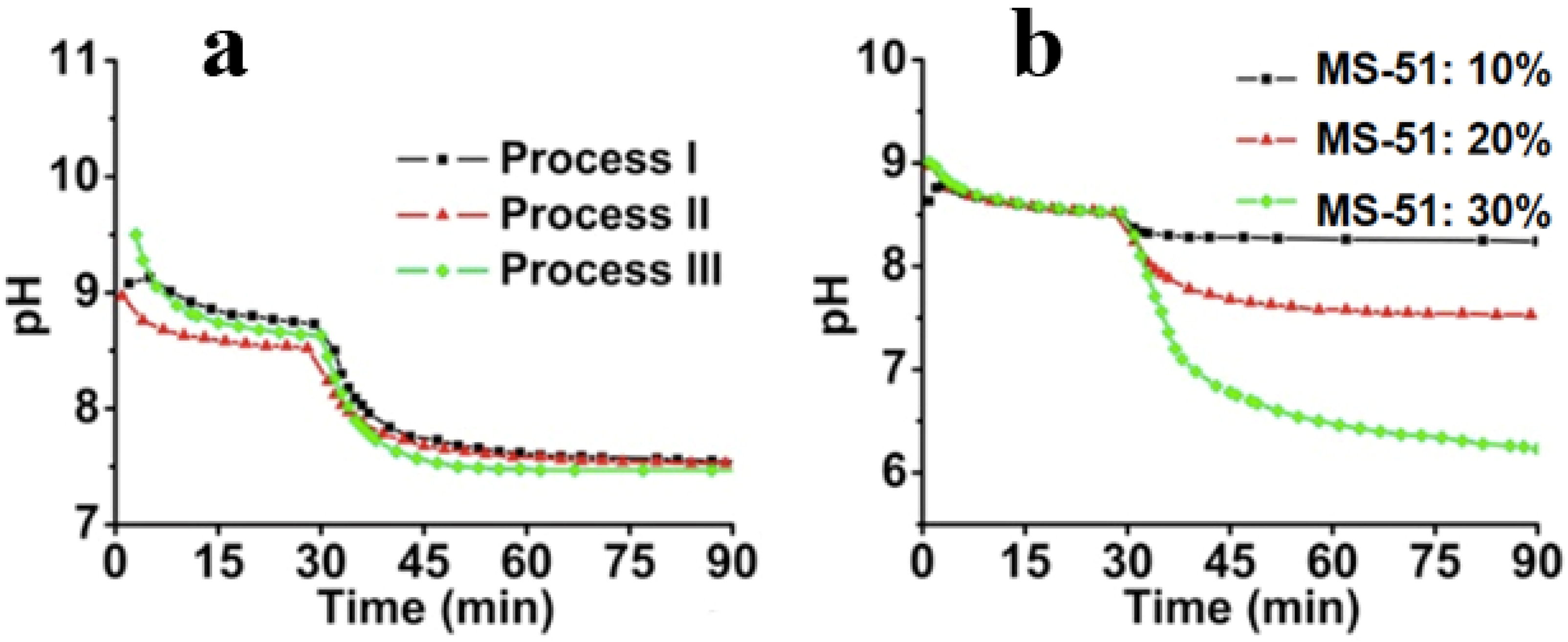
The second issue to be discussed is that of the silica deposition process on the LPEI surfaces. After the organization and crystallization of LPEI in the first stage, it was suggested that the amorphous LPEI existing on the crystalline backbone promotes the hydrolytic condensation of MS-51. To monitor the deposition process, the dynamic pH change was recorded as shown in
Figure 4. Here, the starting point to determine the pH value was the time of mixing the hot LPEI solution with crushed ice. During the initial 30 min, the hot LPEI solution cooled down to thermo-equilibrium state. At 30 min, MS-51 was added, and stirred for 60 min to complete the hydrolytic condensation reaction.
Figure 4a shows the dynamic change of pH within different processes. It can be seen that after 15 min following the addition of ice, the pH began to plateau, indicating the closing of the crystallization. After the addition of MS-51, it also took approximately 15 min for the pH to become steady, meaning that the deposition of silica proceeded quickly to a large degree. In spite of the differences of
mice, the pH curves are fairly similar. In
Figure 4b, the influence of MS-51 concentration on the pH was also investigated. Obviously, the final pH was correlated with concentrations of silica source. When MS-51 concentration was 30%, the final pH even closed to 6, indicating that high concentration of silica source led to low pH value.
Figure 4.
Time-course of pH change. (a) pH change curves under different cooling processes (different mice) by fixing 5 wt % LPEI and 10 vol % MS-51; (b) pH change curves under different concentrations of MS-51 by fixing 10 wt % LPEI in Process-II (mice = 10 g).
Figure 4.
Time-course of pH change. (a) pH change curves under different cooling processes (different mice) by fixing 5 wt % LPEI and 10 vol % MS-51; (b) pH change curves under different concentrations of MS-51 by fixing 10 wt % LPEI in Process-II (mice = 10 g).
The decline of pH offers us some information on LPEI-SiO
2 interfaces. In the hot LPEI solution, because a lot of the –NH– functional groups in LPEI, which was dissolved molecularly, can accept protons from H
2O, the hot solution should be relatively basic. After cooling, the LPEI self-assemble to aggregates and a limited amount of –NH– group will be localized on the surface of LPEI aggregates and forms an interface with water. This interface offers free OH
− in water phase so that pH value appears above 8.5. Choosing Process-II as a typical instant, we compared the influences of the concentration of MS-51 on the pH values in silica deposition. As seen in
Figure 4b, after the addition of MS-51, the pH began to decrease with time. Here, the final pH after 90 min appeared at 8.4, 7.5 and 6.3, respectively, when MS-51 was 10%, 20% and 30%. To address the decline of pH, it is necessary to mention the mechanism of the amine group on LPEI aggregates in promoting the hydrolytic condensation of alkoxysilane. In fact, the groups of –NH– on LPEI aggregates play as catalysts for hydrolysis and condensation of alkoxysilane. During the progress of hydrolytic condensation, silica deposited around the exposed amine groups on the surface of LPEI aggregate and thus LPEI-H
2O interface was quickly replaced by LPEI-SiO
2. Consequently, the silica shell formed surrounding LPEI aggregates will neutralize the LPEI because the silica is weakly acidic, resulting in the pH decline.
Figure 4b indicates unambiguously that when the mass of silica shell surrounding LPEI is low (
i.e., MS-51 concentration is low), the declined degree of pH is small. In contrast, as mass of silica deposited is high, the declined degree of pH is large (
i.e., the pH is lowered evidently). In addition, we can say that the silica deposition capacity become large when the concentration of LPEI was increased to 5%. In this case, 10% MS-51 (1mL of MS-51 in 9 mL ethanol) is insufficient for terminating the surface power to silica deposition.
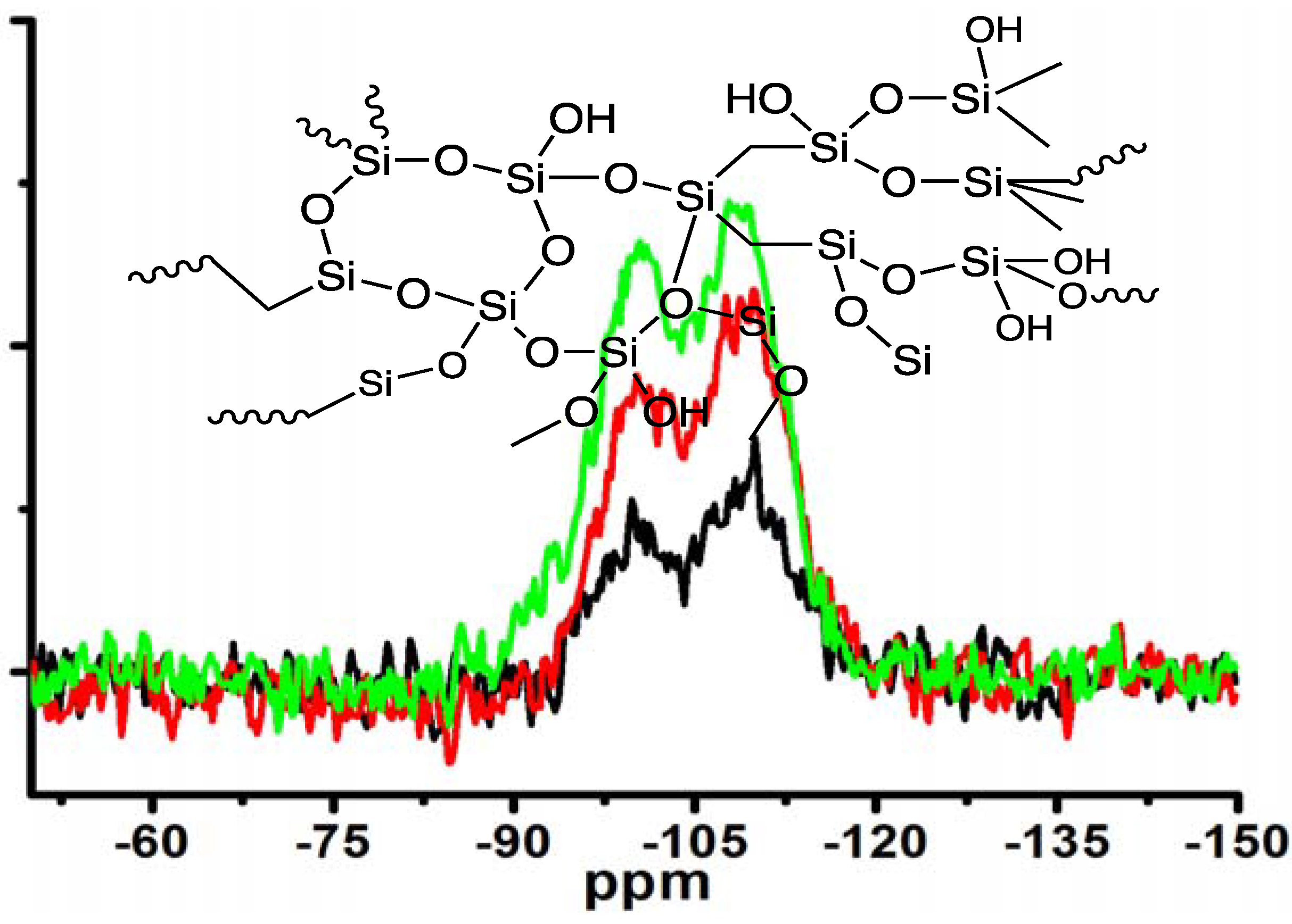
Moreover, the silica obtained under different concentrations of MS-51 while fixing LPEI concentration in Process-II was subjected to measurement of
29Si CPMAS NMR spectra (
Figure 5). Two signals on the NMR spectra at −100 ppm and −110 ppm are assigned to Q3 (HOSi(OSi–)
3) and Q4 (Si(OSi–)
4), respectively. The estimated ratio of Q3/Q4 increased from 0.62, to 0.89, to 1.20 as the concentrations of MS-51 changed from 10, to 20 and to 30 vol %. Considering the hydrolytic condensation process of silica source, at the beginning the polycondensation grows towards branching dimension with a sufficient number of siloxane bonds (Si–O–Si) due to basicity of the surfaces of LPEI templates. However, as the mass of silica shell surrounding the LPEI aggregates increased, the basicity of its surface decreased. This basicity decline will suppress the branching growing of Si–O–Si but allow the polycondensation growing with linear fashion. Consequently, the Q4 bonding fraction decreased while Q3 bonding fraction increased when deposited silica increased (
i.e., at the higher concentration of MS-51).
Figure 5.
29Si CPMAS NMR spectra of the samples under different concentrations of MS-51 by fixing 10 wt % LPEI in Process-II (mice = 10 g). Insert: schematic description of amorphous silica. Black line: 10 vol % MS-51; Red line: 20 vol % MS-51; Green line: 30 vol % MS-51.
Figure 5.
29Si CPMAS NMR spectra of the samples under different concentrations of MS-51 by fixing 10 wt % LPEI in Process-II (mice = 10 g). Insert: schematic description of amorphous silica. Black line: 10 vol % MS-51; Red line: 20 vol % MS-51; Green line: 30 vol % MS-51.
The process of using the crushed ice to modulate the LPEI crystallization and subsequent silica deposition is quite convenient for scalable production of silica platelets with elemental one-dimension structures. For example, about 10 g of hybrid sample could be collected under the conditions as follows: LPEI (5 wt %, 100 g), 160 g of ice, MS-51 (30 vol %, 100 mL). These hybrids showed the sheet-like platelets appearance with nanowire-knitted structure inside (
Figure S5).
It is known that LPEI can act as a reducing agent and therefore the as-prepared LPEI@SiO
2 can play both as reducing agent and host [
19]. As an application, the LPEI@SiO
2 hybrids obtained under the conditions of (Process-III,
mice = 25 g, 5 wt % LPEI and 30 vol % MS-51) were employed to load Pt nanoparticles as catalyst. Here, just simply mixing PtCl
42− solutions with LPEI@SiO
2 powders, we loaded the Pt nanoparticles on the silica. As shown in
Figure 6a, the HRTEM shows that Pt homogeneously distributed around the silica. The XRD pattern also shows the characteristic peaks of Pt (
Figure S5). Since metallic nanoparticles can be used as catalysts in the organic reactions [
27,
28,
29,
30], we used the Pt-loaded SiO
2 as a catalyst in the reduction of Rhodamine B by DMAB. As shown in
Figure 6b, after mixing the catalyst of Pt-loaded SiO
2 with the solution of containing RhB and DMAB, the absorption at around 553 nm of RhB decreased dramatically with almost de-colored state only within 11 min. In contrast, the solution without addition of the Pt-loaded SiO
2 showed little color change even after 24 h. This contrast indicates that the Pt-loaded SiO
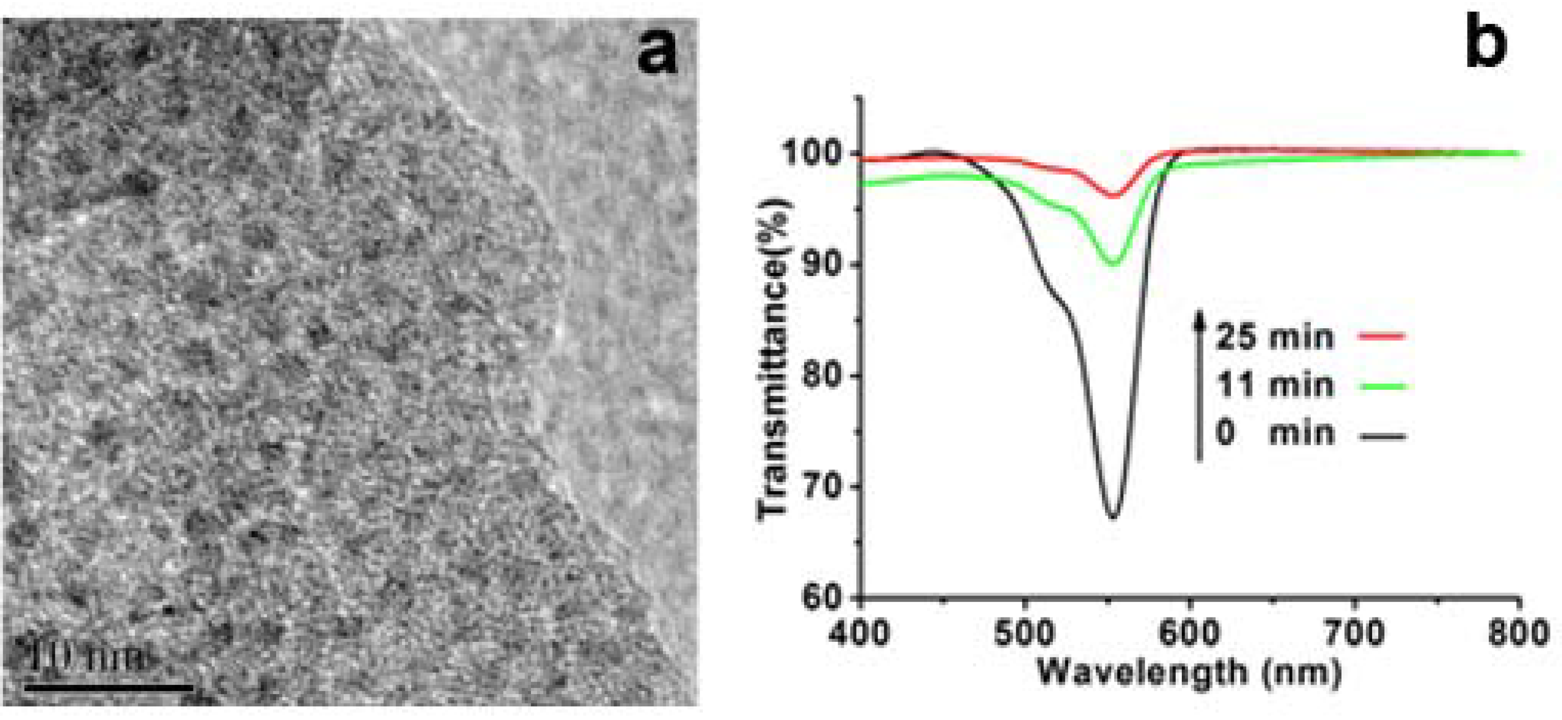
2 is an active catalyst for the reduction of RhB by DMAB. As for the catalytic mechanism, the Pt nanoparticles loaded on silica wire can play as electron pool where the electrons from DMAB are trapped on Pt and then passed to RhB.
Figure 6.
(a) High-resolution transmission electron microscopy (HRTEM) images of Pt-loaded LPEI@SiO2; (b) Time-course spectra of Rhodamine B (RhB) reduced by dimethylaminoborane (DMAB).
Figure 6.
(a) High-resolution transmission electron microscopy (HRTEM) images of Pt-loaded LPEI@SiO2; (b) Time-course spectra of Rhodamine B (RhB) reduced by dimethylaminoborane (DMAB).

