Wear Behavior of Fiber Laser Textured TiN Coatings in a Heavy Loaded Sliding Regime

Abstract
:1. Introduction
2. Experimental Section
2.1. Sample Preparation and Their Quality Assessment
2.2. Laser Surface Texturing

| Laser System Parameters | Numerical Values |
|---|---|
| Maximum average power | 50 W |
| Wavelength | 1064 nm |
| Pulse repetition rate (PRR) | 20–80 kHz |
| M2 | 1.7 |
| Collimated beam diameter | 5.9 mm |
| Focal length | 60 mm |
| Beam waist diameter | 23 µm |
| Pulse no. | Energy /mJ |
|---|---|
| 1 | 0.12 |
| 2 | 0.23 |
| 3 | 0.14 |
| 4 | 0.11 |
| 5 | 0.08 |
| 6 | 0.06 |
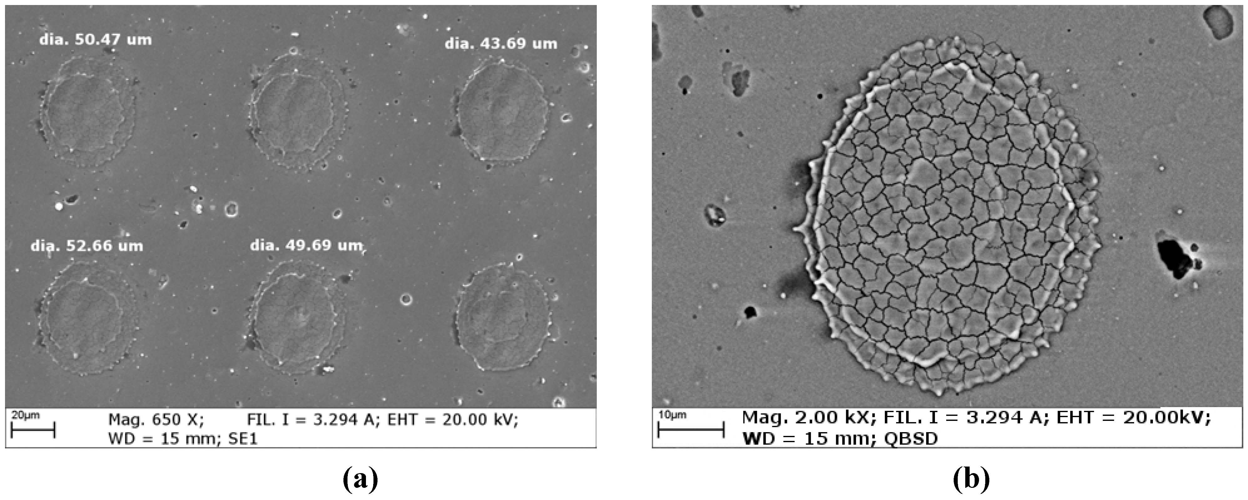
- dimple mean diameter: average diameter of each dimple was determined by measuring it in different positions across its centroid; the measurement line across dimple diameter was progressively rotated by 2 degree intervals around its center axis;
- dimple aspect ratio: the ratio between major axis and minor axis of the equivalent ellipse fitting the dimple profile.
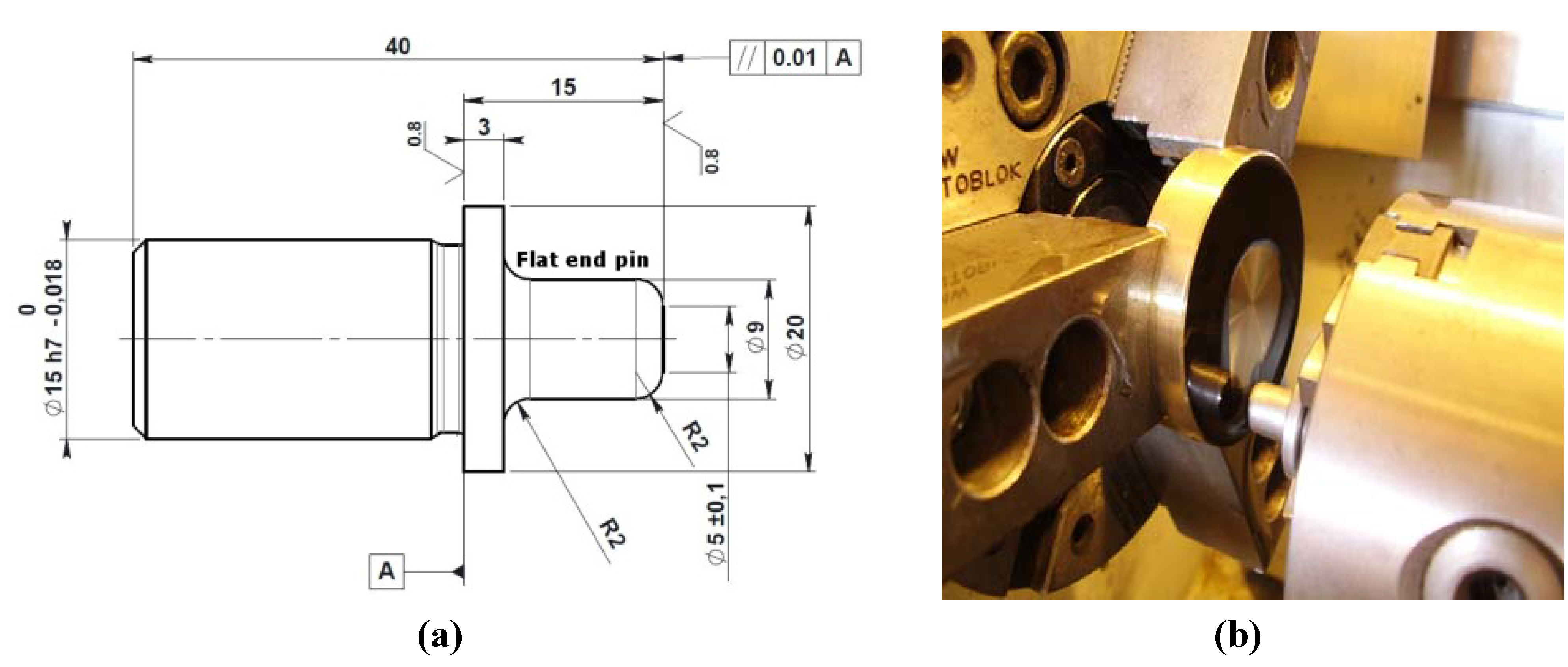
2.3. Flat End Pin on Disc Sliding Wear Test


3. Results
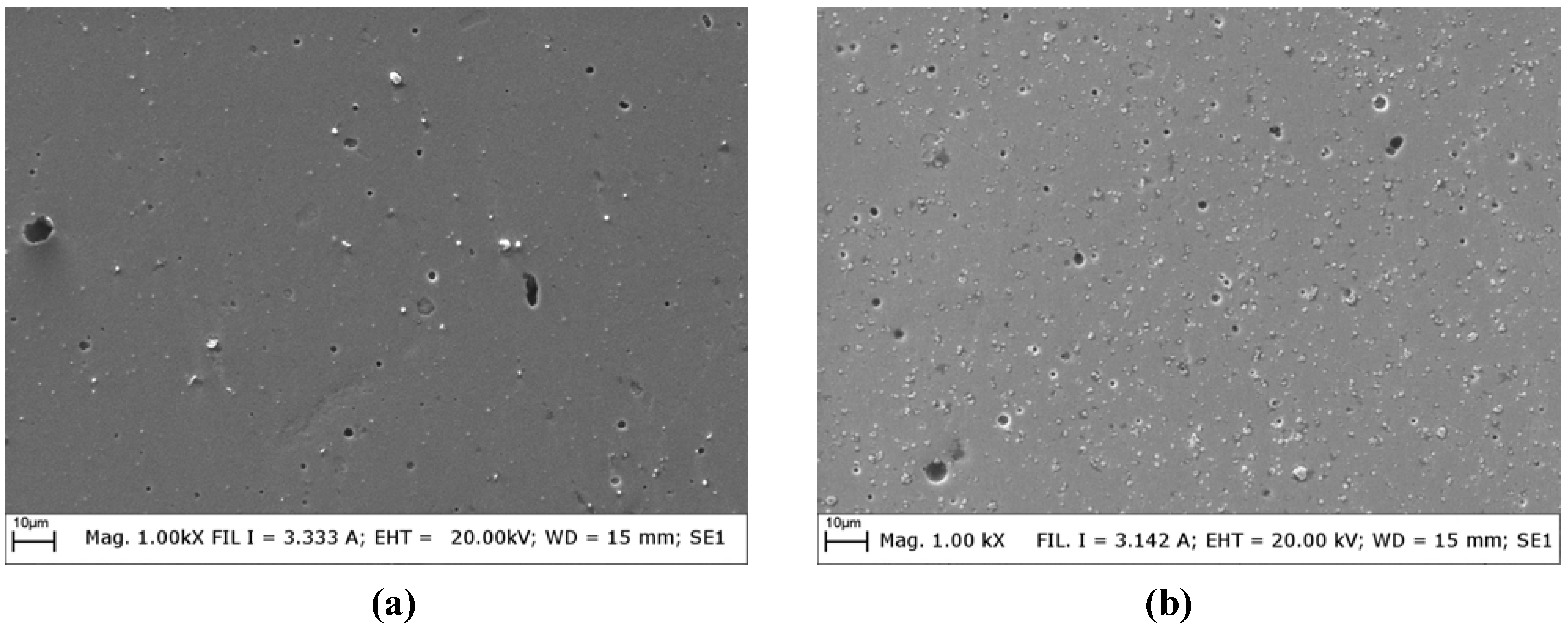
3.1. Structural Characterization of Un-textured Coatings
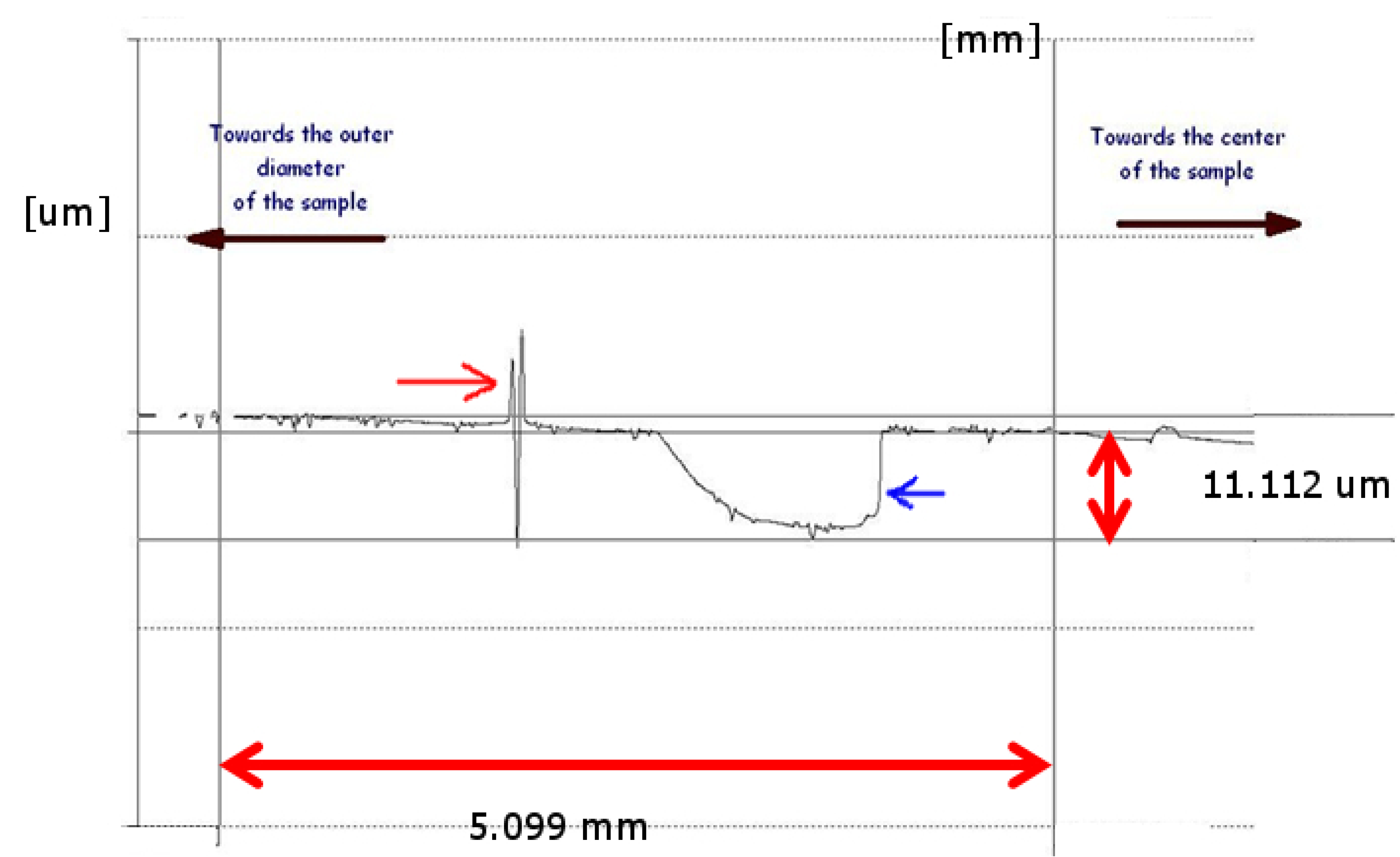
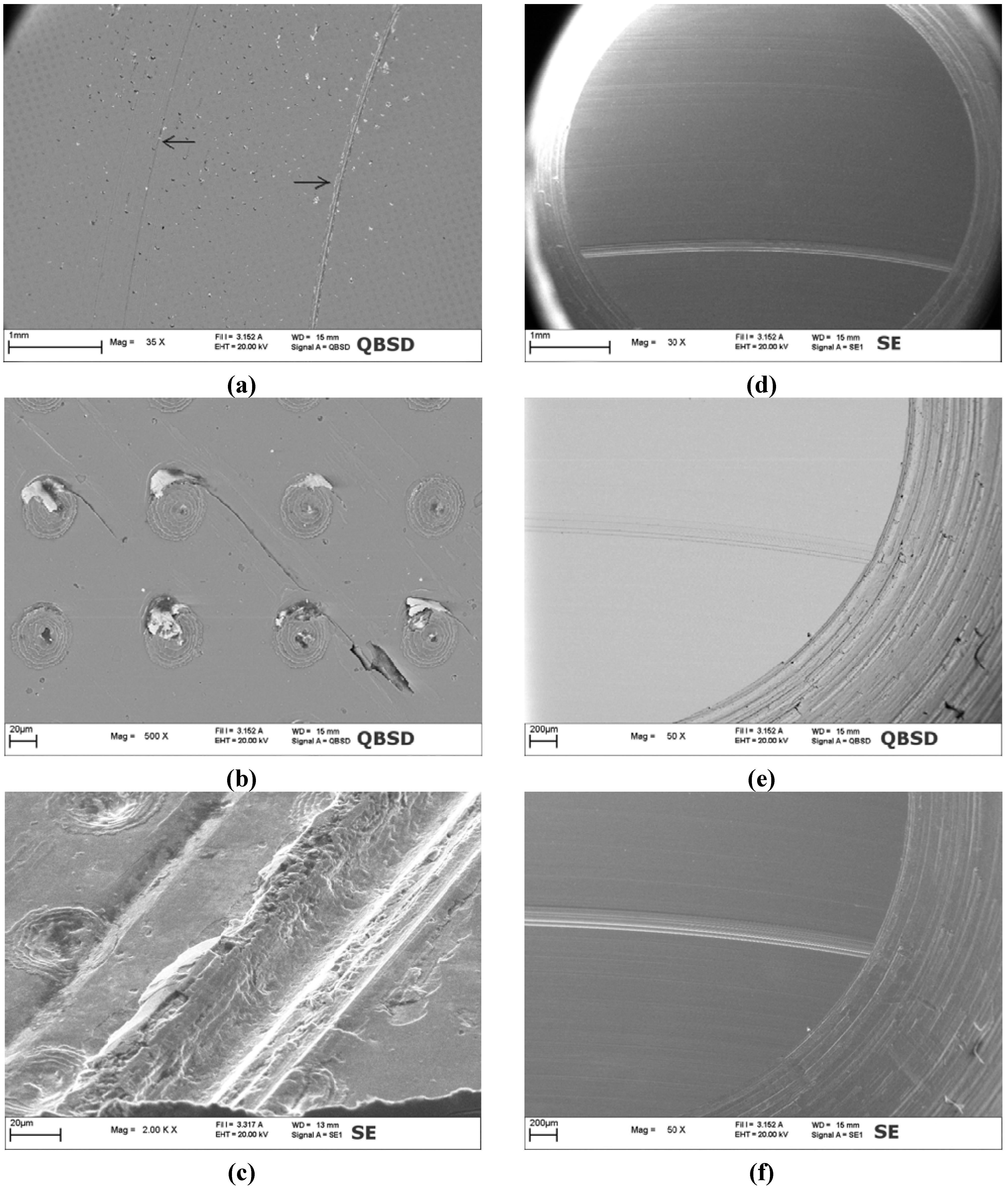
3.2. Morphology of Textured Surface


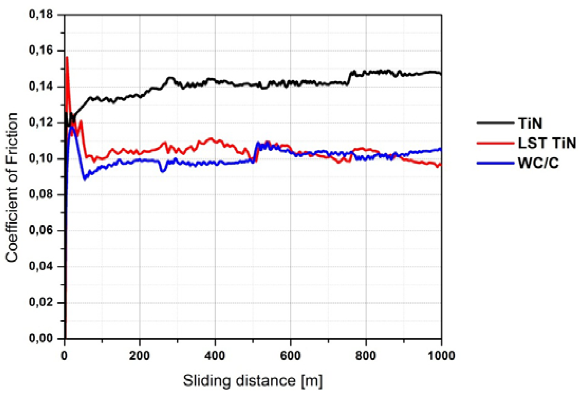
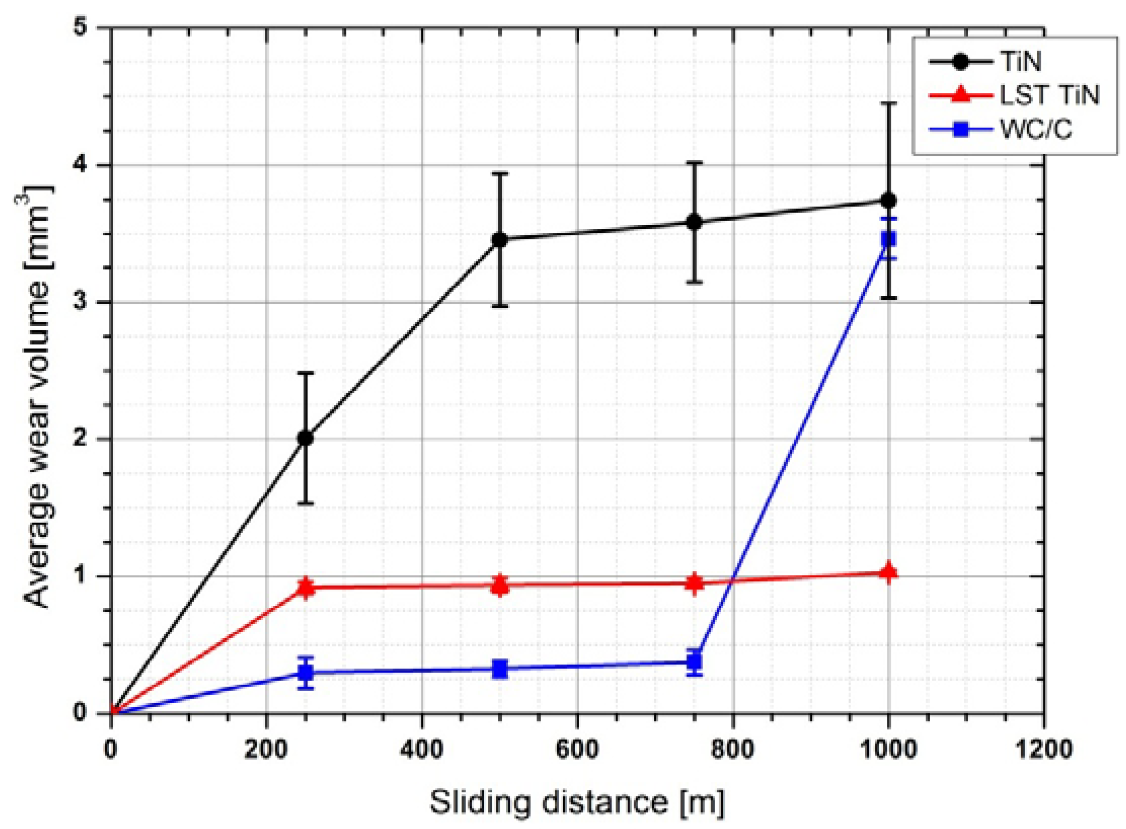
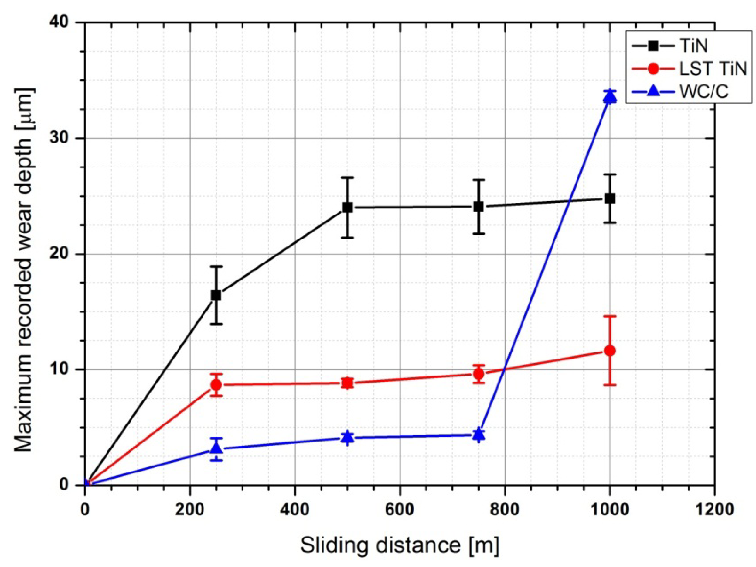
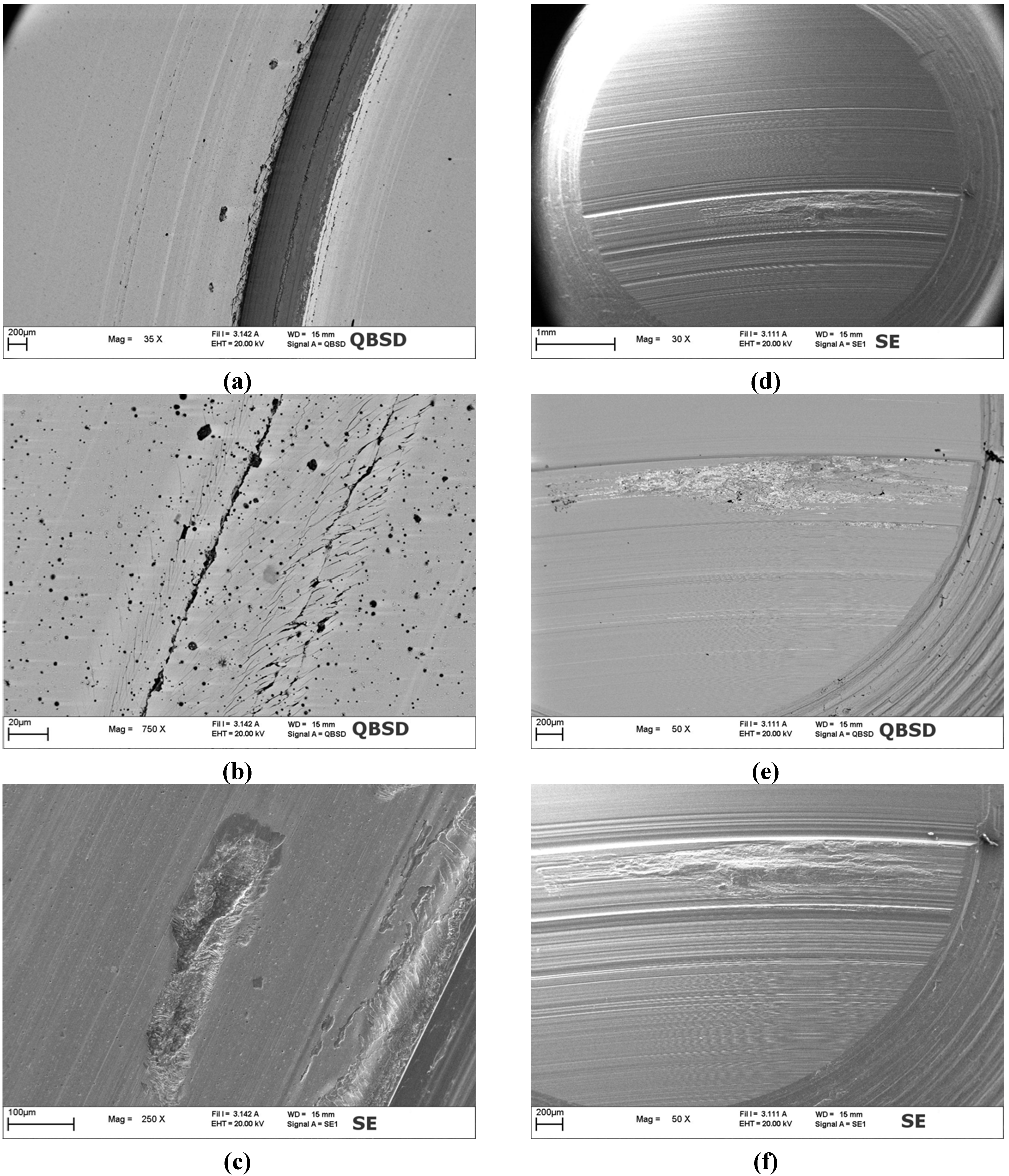
3.3. Wear Behavior


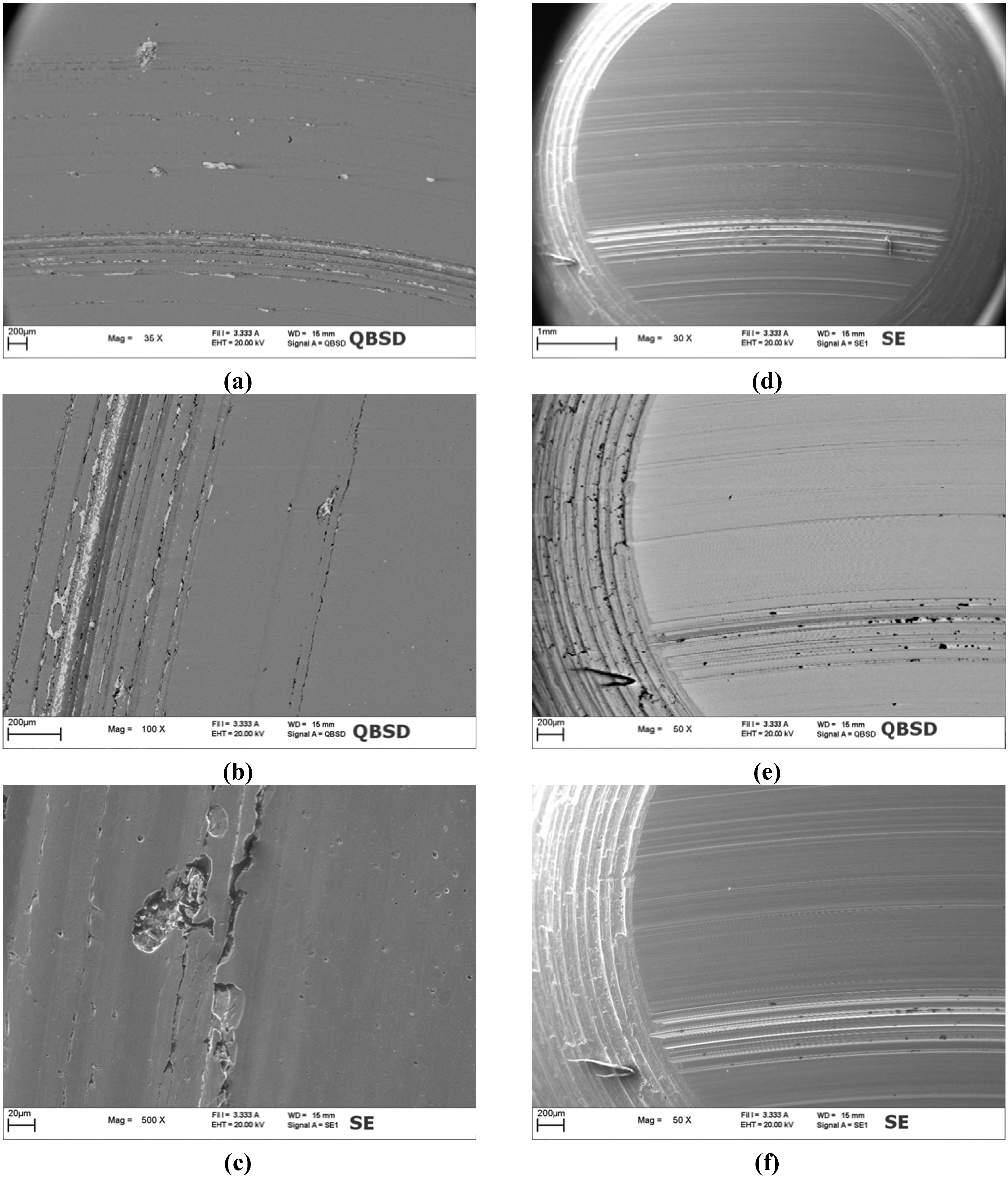
4. Discussion
5. Conclusions
References
- Erdemir, A. Review of engineered tribological interfaces for improved boundary lubrication. Tribol. Int. 2005, 38, 249–256. [Google Scholar] [CrossRef]
- Etsion, I. State of the art in laser surface texturing. J. Tribol. 2005, 127, 248–253. [Google Scholar] [CrossRef]
- Hamilton, D.B.; Walowit, J.A.; Allen, C.M. A theory of lubrication by micro-irregularities. J. Basic Eng. 1966, 88, 177–185. [Google Scholar] [CrossRef]
- Pei, S.; Ma, S.; Xu, H.; Wang, F.; Zhang, Y. A multiscale method of modeling surface texture in hydrodynamic regime. Tribol. Int. 2011, 44, 1810–1818. [Google Scholar] [CrossRef]
- Tala-Ighil, N.; Fillon, M.; Maspeyrot, P. Effect of textured area on the performances of a hydrodynamic journal bearing. Tribol. Int. 2011, 44, 211–219. [Google Scholar] [CrossRef]
- Ramesh, A.; Akram, W.; Mishra, S.P.; Cannon, A.H.; Polycarpou, A.A.; King, W.P. Friction characteristics of microtextured surfaces under mixed and hydrodynamic lubrication. Tribol. Int. 2013, 57, 170–176. [Google Scholar] [CrossRef]
- Bizi-Bandokia, P.; Benayouna, S.; Valettea, S.; Beaugirauda, B.; Audouardb, E. Modifications of roughness and wettability properties of metals induced by femtosecond laser treatment. Appl. Surf. Sci. 2011, 257, 5213–5218. [Google Scholar] [CrossRef]
- Vikram, V.I.; Barada, K.N.; Mool, C.G. Ultralow reflectance metal surfaces by ultrafast laser texturing. Appl. Optics 2010, 49, 5983–5988. [Google Scholar] [CrossRef]
- Barada, K.N.; Mool, C.G. Self-organized micro/nano structures in metal surfaces by ultrafast laser irradiation. Optics Lasers Eng. 2010, 48, 940–949. [Google Scholar] [CrossRef]
- Ryk, G.; Etsion, I. Testing piston rings with partial laser surface texturing for friction reduction. Wear 2006, 261, 792–796. [Google Scholar] [CrossRef]
- Etsion, I.; Halperin, G.; Becker, E. The effect of various surface treatments on piston pin scuffing resistance. Wear 2006, 261, 785–791. [Google Scholar] [CrossRef]
- Etsion, I. Improving tribological performance of mechanical components by laser surface texturing. Tribol. Lett. 2004, 17, 733–737. [Google Scholar] [CrossRef]
- Wan, Y.; Xiong, D.S. The effect of laser surface texturing on frictional performance of face seal. J. Mat. Process. Technol. 2008, 197, 96–100. [Google Scholar] [CrossRef]
- Kovalchenko, A.; Ajayi, O.; Erdemir, A.; Fenske, G.; Etsion, I. The effect of laser surface texturing on transitions in lubrication regimes during unidirectional sliding contact. Tribol. Int. 2005, 38, 219–225. [Google Scholar] [CrossRef]
- Deng, J.; Wu, Z.; Lian, Y.; Qi, T.; Cheng, J. Performance of carbide tools with textured rake-face filled with solid lubricants in dry cutting processes. Int. J. Refract. Met. Hard Mat. 2012, 30, 164–172. [Google Scholar] [CrossRef]
- Schreck, S.; Gahr, Z.K.-H. Laser-assisted structuring of ceramic and steel surfaces for improving tribological properties. Appl. Surf. Sci. 2005, 247, 616–622. [Google Scholar] [CrossRef]
- Popp, U.; Engel, U. Microtexturing of cold-forging tools—influence on tool life. J. Eng. Manuf. 2006, 220, 27–33. [Google Scholar] [CrossRef]
- Vincent, C.; Monteil, G.; Barriere, T.; Gelin, J.C. Control of the quality of laser surface texturing. Microsyst. Technol. 2008, 14, 1553–1557. [Google Scholar] [CrossRef]
- Vilhena, L.M.; Sedlaček, M.; Podgornik, B.; Vižintin, J.; Babnik, A.; Možina, J. Surface texturing by pulsed Nd:YAG laser. Tribol. Int. 2009, 42, 1496–1504. [Google Scholar] [CrossRef]
- Andersson, P.; Koskinen, J.; Varjus, S.; Gerbig, Y.; Haefke, H.; Georgiou, S.; Zhmud, B.; Buss, W. Microlubrication effect by laser-textured steel surfaces. Wear 2007, 262, 369–379. [Google Scholar] [CrossRef]
- Chichkov, B.N.; Momma, C.; Nolte, S.; Von Alvensleben, F.; Tünnermann, A. Femtosecond, picosecond and nanosecond laser ablation of solids. Appl. Phys. A Mat. Sci. Process. 1996, 63, 109–115. [Google Scholar] [CrossRef]
- Mourier, L.; Mazuyer, D.; Lubrecht, A.A.; Donnet, C.; Audouard, E. Action of a femtosecond laser generated micro-cavity passing through a circular EHL contact. Wear 2008, 264, 450–456. [Google Scholar] [CrossRef]
- Kononenko, T.V.; Garnov, S.V.; Pimenov, S.M.; Konov, V.I.; Romano, V.; Borsos, B.; Weber, H.P. Laser ablation and micropatterning of thin TiN coatings. Appl. Phys. A Mat. Sci. Process. 2000, 71, 627–631. [Google Scholar] [CrossRef]
- Trtica, M.S.; Tarasenko, V.F.; Gaković, B.M.; Fedenev, A.V.; Petkovska, L.T.; Radak, B.B.; Lipatov, E.I.; Shulepov, M.A. Surface modifications of TiN coating by pulsed TEA CO2 and XeCl lasers. Appl. Surf. Sci. 2005, 252, 474–482. [Google Scholar] [CrossRef]
- Dumitru, G.; Romano, V.; Weber, P.H.; Pimenov, S.; Kononenko, T.; Sentis, M.; Hermann, J.; Bruneau, S. Femtosecond laser ablation of diamond like carbon films. Appl. Surf. Sci. 2004, 222, 226–233. [Google Scholar] [CrossRef]
- Neves, D.; Diniz, A.E.; de Lima, M.S.F. Efficiency of the laser texturing on the adhesion of the coated twist drills. J. Mater. Process. Technol. 2006, 179, 139–145. [Google Scholar] [CrossRef]
- Higuera, G.A.; Gonzalez, R.; Cadenas, M.; Viesca, J.L. NiCrBSi coatings textured by Nd-YAG laser. Int. J. Surf. Sci. Eng. 2011, 5, 75–97. [Google Scholar] [CrossRef]
- Liu, A.; Deng, J.; Cui, H.; Chen, Y.; Zhao, J. Friction and wear properties of TiN, TiAlN, AlTiN and CrAlN PVD nitride coatings. Int. J. Refract. Met. Hard Mat. 2012, 31, 82–88. [Google Scholar] [CrossRef]
- Heck, S.; Emmerich, T.; Munder, I.; Steinebrunner, J. Tribological behaviour of Ti-Al-B-N-based PVD coatings. Surf. Coat. Technol. 1996, 86–87, 467–471. [Google Scholar] [CrossRef]
- Eriksson, J.; Olsson, M. Tribological testing of commercial CrN, (Ti,Al)N and CrC/C PVD coatings—Evaluation of galling and wear characteristics against different high strength steels. Surf. Coat. Technol. 2011, 205, 4045–4051. [Google Scholar] [CrossRef]
- Rosso, M.; Ugues, D.; Torres, E.; Perucca, M.; Kapranos, P. Performance enhancements of die casting tools trough PVD nanocoatings. Int. J. Mat. Form. 2008, 1, 1259–1262. [Google Scholar] [CrossRef]
- Rapoport, L.; Moshkovich, A.; Perfilyev, V.; Lapsker, I.; Halperin, G.; Itovich, Y.; Etsion, I. Friction and wear of MoS2 films on laser textured steel surface. Surf. Coat. Technol. 2008, 202, 3332–3340. [Google Scholar] [CrossRef]
- Rapoport, L.; Moshkovich, A.; Perfilyev, V.; Gedanken, A.; Koltypin, Yu.; Sominski, E.; Halperin, G.; Etsion, I. Wear life and adhesion of solid lubricant films on laser textured steel surface. Wear 2009, 267, 1203–1207. [Google Scholar] [CrossRef]
- Voevodin, A.A.; Zabinski, J.S. Laser surface texturing for adaptive solid lubrication. Wear 2006, 261, 1285–1292. [Google Scholar] [CrossRef]
- Gao, Y.; Wu, B.; Zhou, Y.; Tao, S. A two-step nanosecond laser surface texturing process with smooth surface finish. Appl. Surf. Sci. 2011, 257, 9960–9967. [Google Scholar] [CrossRef]
- Demir, A.G.; Previtali, B.; Lecis, N.; Vandoni, L.; Ugues, D. Fiber laser surface texturing of PVD coatings and their tribological behaviour. Metall. Ital. 2012, 6, 15–19. [Google Scholar]
- Evans, D.C.; Senior, G.S. Self-lubricating materials for plain bearings. Tribol. Int. 1982, 15, 243–248. [Google Scholar] [CrossRef]
- Blau, P. Use of Textured Surfaces to Mitigate Sliding Friction and Wear of Lubricated and Non-Lubricated Contacts. An annotated literature review. Oak Ridge National Laboratory Website. Available on line: http://www.osti.gov/bridge (accessed on 29 September 2012).
- Koszela, W.; Pawlus, P.; Galda, L. The effect of oil pockets size and distribution on wear in lubricated sliding. Wear 2007, 263, 1585–1592. [Google Scholar] [CrossRef]
- Johnson, K.L. Contact Mechanics; Cambridge University Press: Cambridge, UK, 2001; pp. 129–134. [Google Scholar]
- Goodier, J.N.; Loutzenheiser, C.B. Pressure peaks at the ends of plane strain rigid die contacts (Elastic). J. Appl. Mech. 1965, 32, 462–463. [Google Scholar] [CrossRef]
- Ciavarella, M.; Hills, D.A.; Monno, G. The influence of rounded edges on indentation by a flat punch. J. Mech. Eng. Sci. 1998, 212, 319–328. [Google Scholar] [CrossRef]
- Ciavarella, M.; Macina, G. New results for the fretting-induced stress concentration on Hertzian and flat rounded contacts. Int. J. Mech. Sci. 2003, 45, 449–467. [Google Scholar] [CrossRef]
- Jager, J. New analytical and numerical results for two dimensional contact profiles. Int. J. Sol. Struct. 2002, 39, 959–972. [Google Scholar] [CrossRef]
- Bonse, J.; Geuß, M.; Baudach, S.; Sturm, H.; Kautek, W. The precision of the femtosecond-pulse laser ablation of TiN films on silicon. Appl. Phys. A Mat. Sci. Process. 1999, 69, 399–402. [Google Scholar] [CrossRef]
- Mo, J.L.; Zhu, M.H. Tribological investigation of WC/C coating under dry sliding conditions. Wear 2011, 271, 1998–2005. [Google Scholar] [CrossRef]
- Liu, Y.; Gubisch, M.; Hild, W.; Scherge, M.; Spiess, L.; Knedlik, Ch.; Schaefler, J.A. Nanoscale multilayer WC/C coatings developed for nanopositioning, part II: Friction and wear. Thin Solid Films 2005, 488, 140–148. [Google Scholar] [CrossRef]
- Harlin, P.; Bexell, U.; Olsson, M. Influence of surface topography of arc-deposited TiN and sputter-deposited WC/C coatings on the initial material transfer tendency and friction characteristics under dry sliding contact conditions. Surf. Coat. Technol. 2009, 203, 1748–1755. [Google Scholar] [CrossRef]
© 2012 by the authors; licensee MDPI, Basel, Switzerland. This article is an open access article distributed under the terms and conditions of the Creative Commons Attribution license (http://creativecommons.org/licenses/by/3.0/).
Share and Cite
Vandoni, L.; Demir, A.G.; Previtali, B.; Lecis, N.; Ugues, D. Wear Behavior of Fiber Laser Textured TiN Coatings in a Heavy Loaded Sliding Regime. Materials 2012, 5, 2360-2382. https://doi.org/10.3390/ma5112360
Vandoni L, Demir AG, Previtali B, Lecis N, Ugues D. Wear Behavior of Fiber Laser Textured TiN Coatings in a Heavy Loaded Sliding Regime. Materials. 2012; 5(11):2360-2382. https://doi.org/10.3390/ma5112360
Chicago/Turabian StyleVandoni, Laura, Ali Gökhan Demir, Barbara Previtali, Nora Lecis, and Daniele Ugues. 2012. "Wear Behavior of Fiber Laser Textured TiN Coatings in a Heavy Loaded Sliding Regime" Materials 5, no. 11: 2360-2382. https://doi.org/10.3390/ma5112360