A Novel Fractional Order Model for the Dynamic Hysteresis of Piezoelectrically Actuated Fast Tool Servo

Abstract
:1. Introduction
2. A Brief Review of Related Work
3. A Preliminary to Fractional Order Calculus
4. Fractional Order Hysteresis Model of the FTS
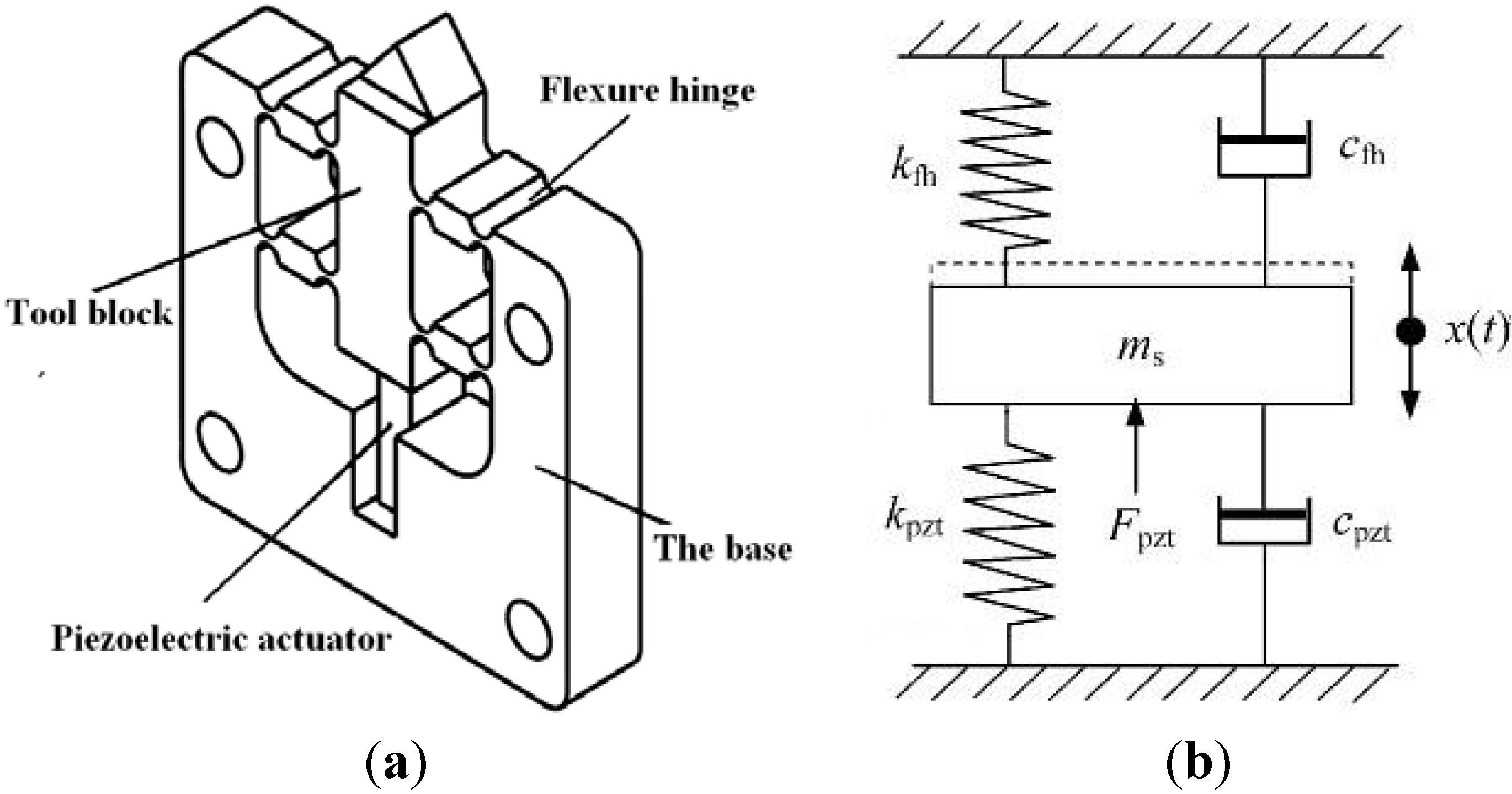
4.1. Dynamic Model of the FTS Mechanism

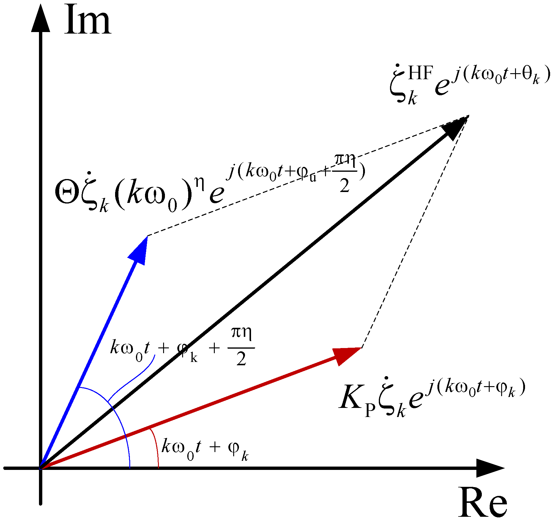
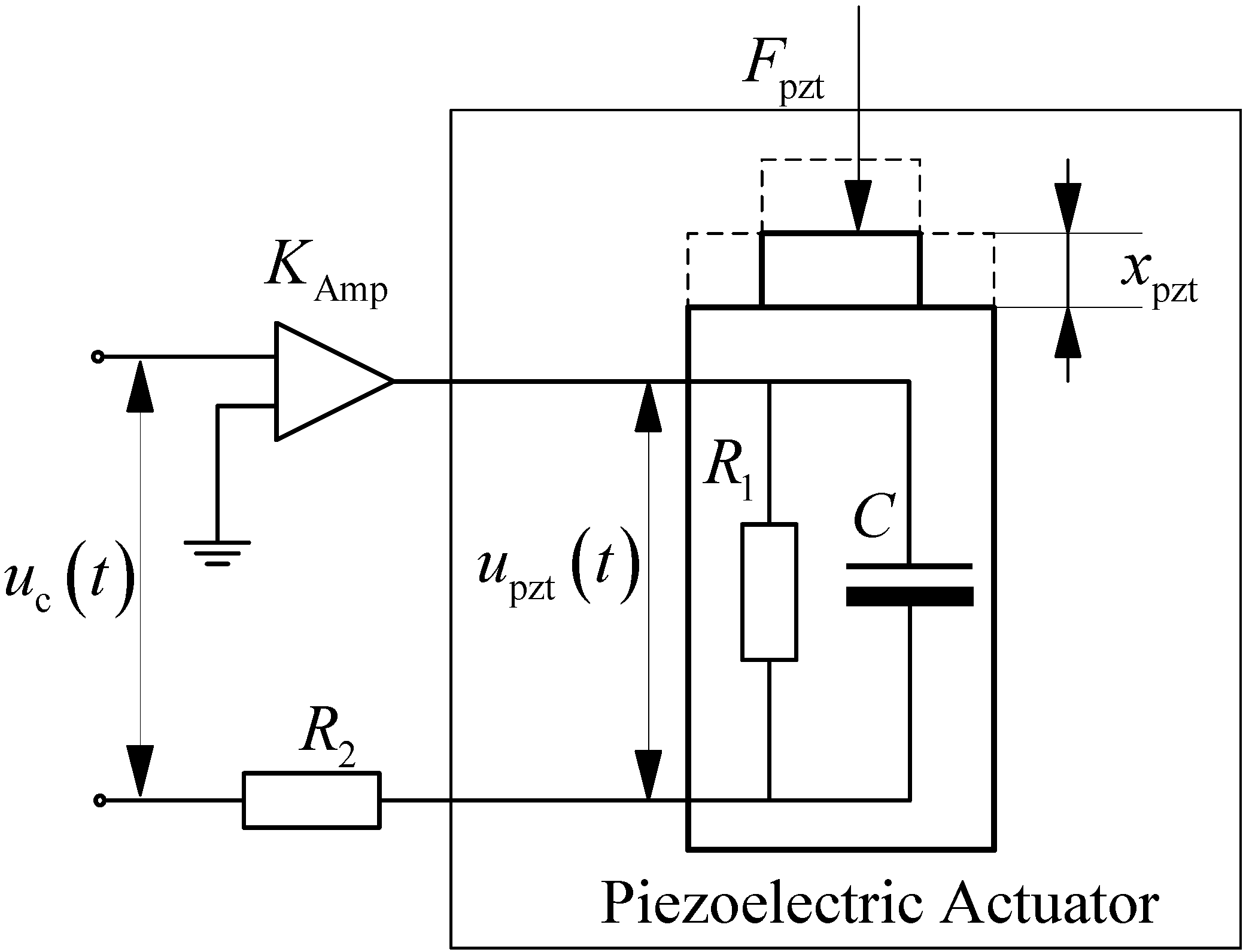
4.2. Hysteresis Model of the FTS
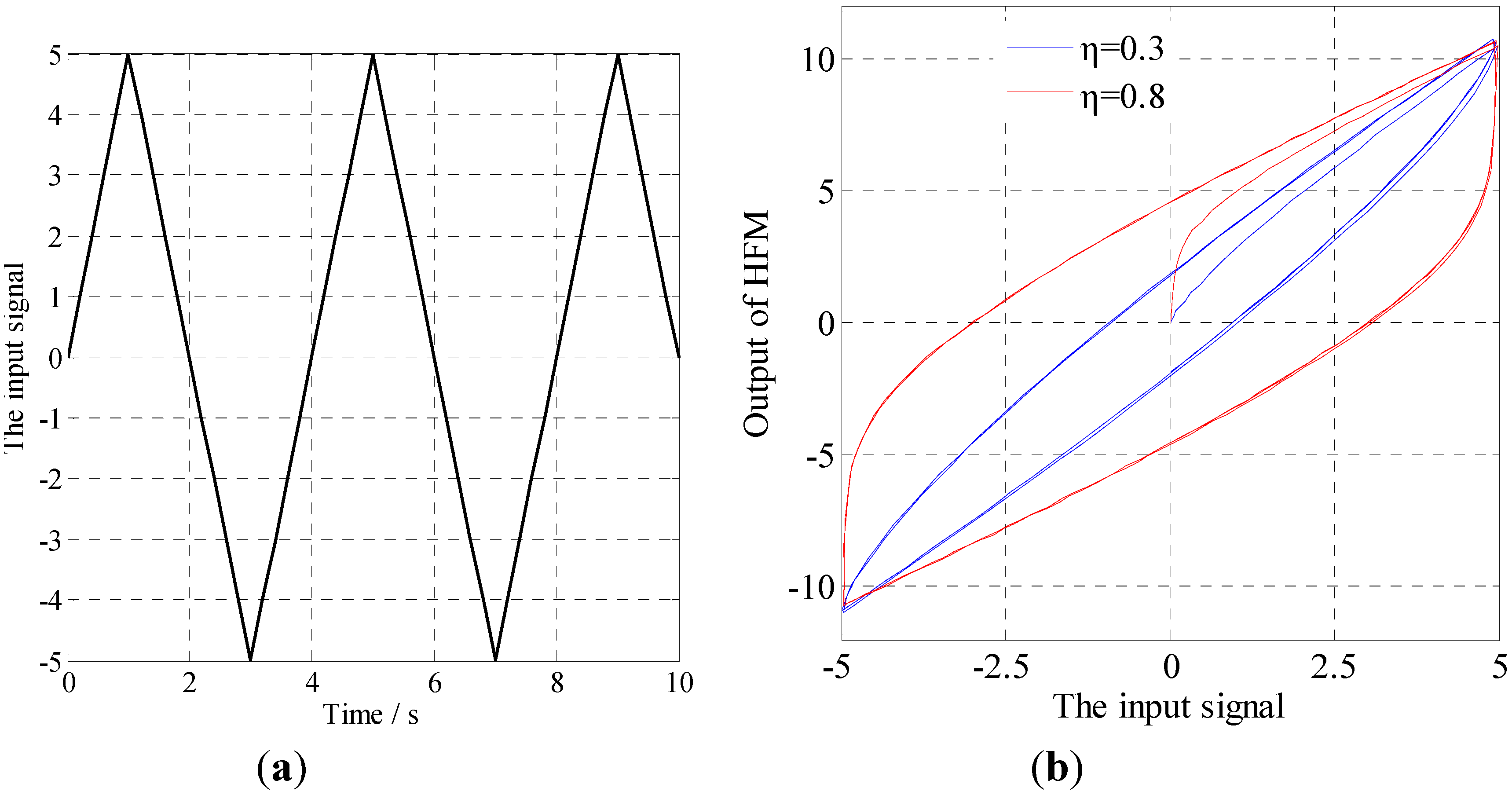
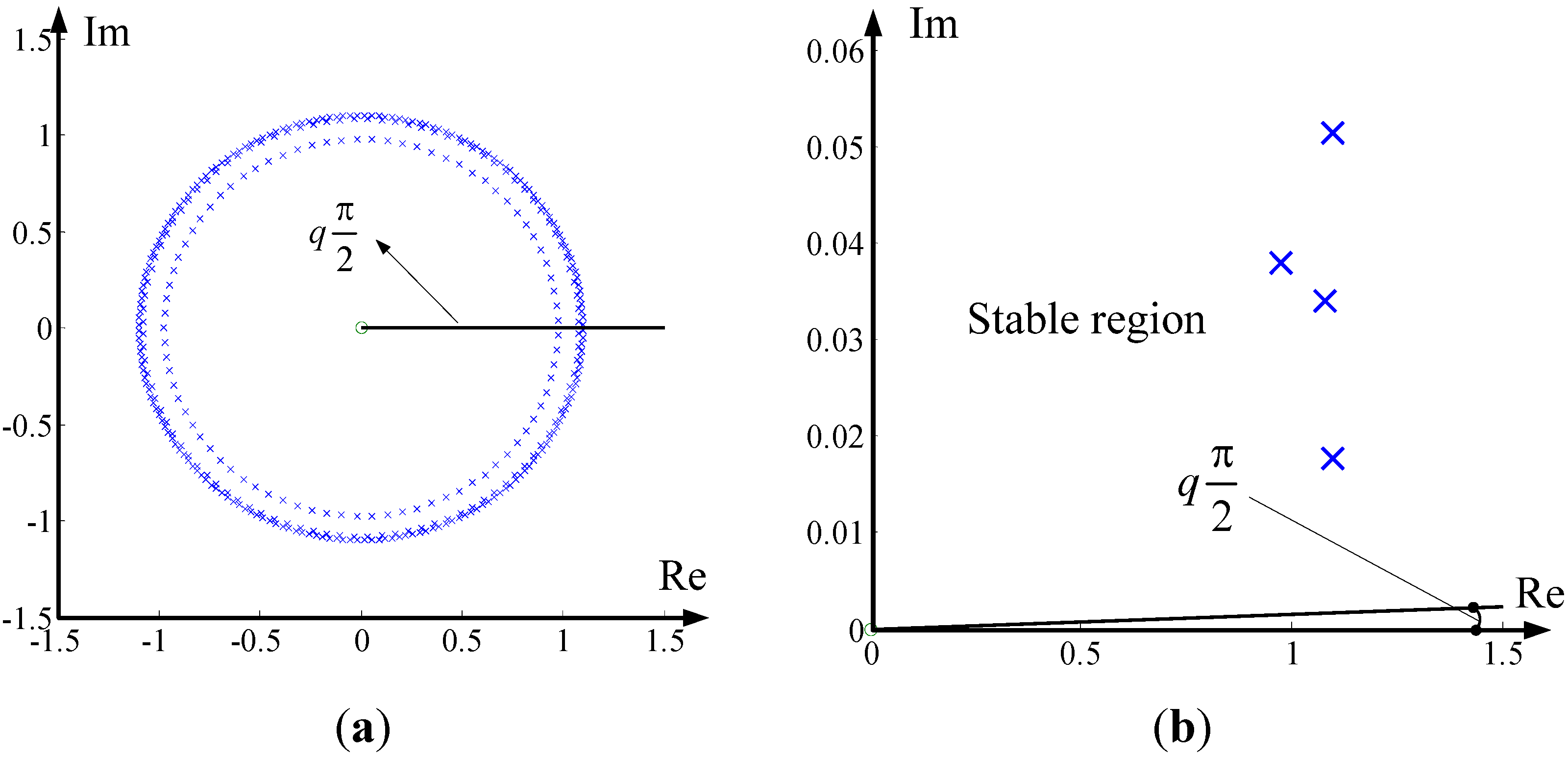
4.3. Properties of the Hysteresis Force Model

5. Experiment Results and Discussion
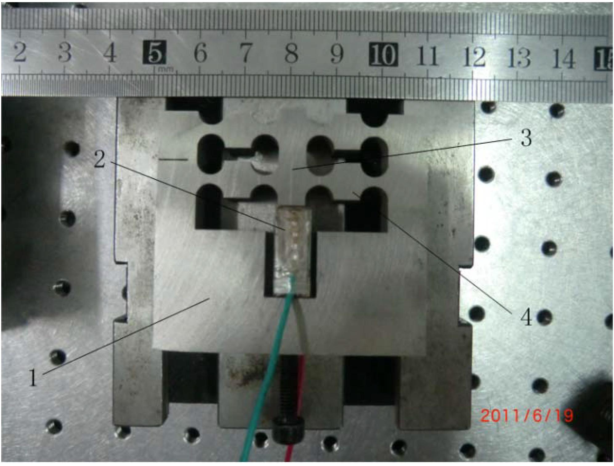
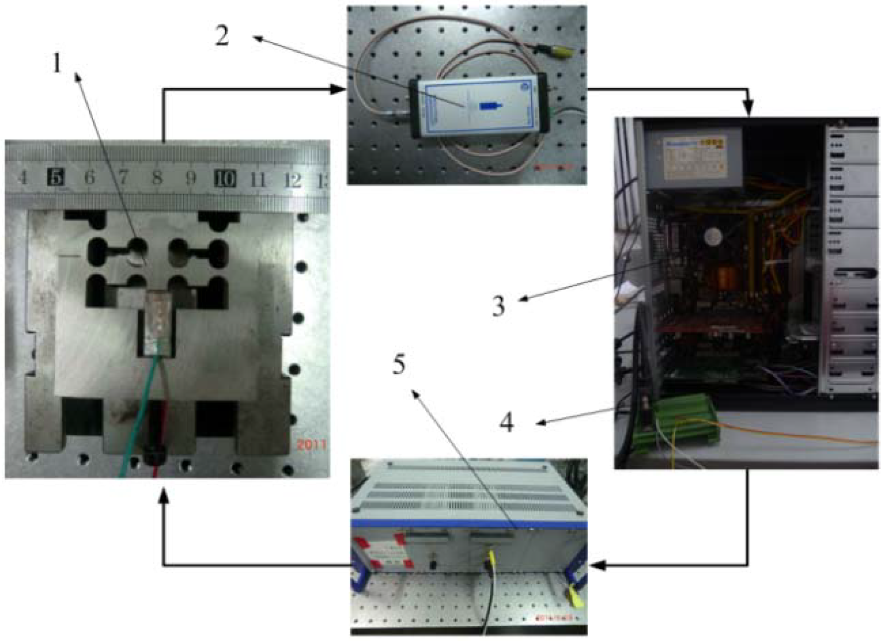
5.1. Experiment Setup

5.2. Parameter Estimation of the Model

| Parameters | Value |
|---|---|
| KM | 1.71e + 8 |
| ζ | 0.031 |
| ωn | 1.28e + 4 |
| τ | 4.18 e − 4 |
| η | 0.756 |
| λ | 0.811 |
| Kp | 0.192 |
| Θ | 5.923 |
| χ | 6.897 |
| ρ | −0.140 |
| δ | 0.072 |

5.3. Validation of the Hysteresis Model
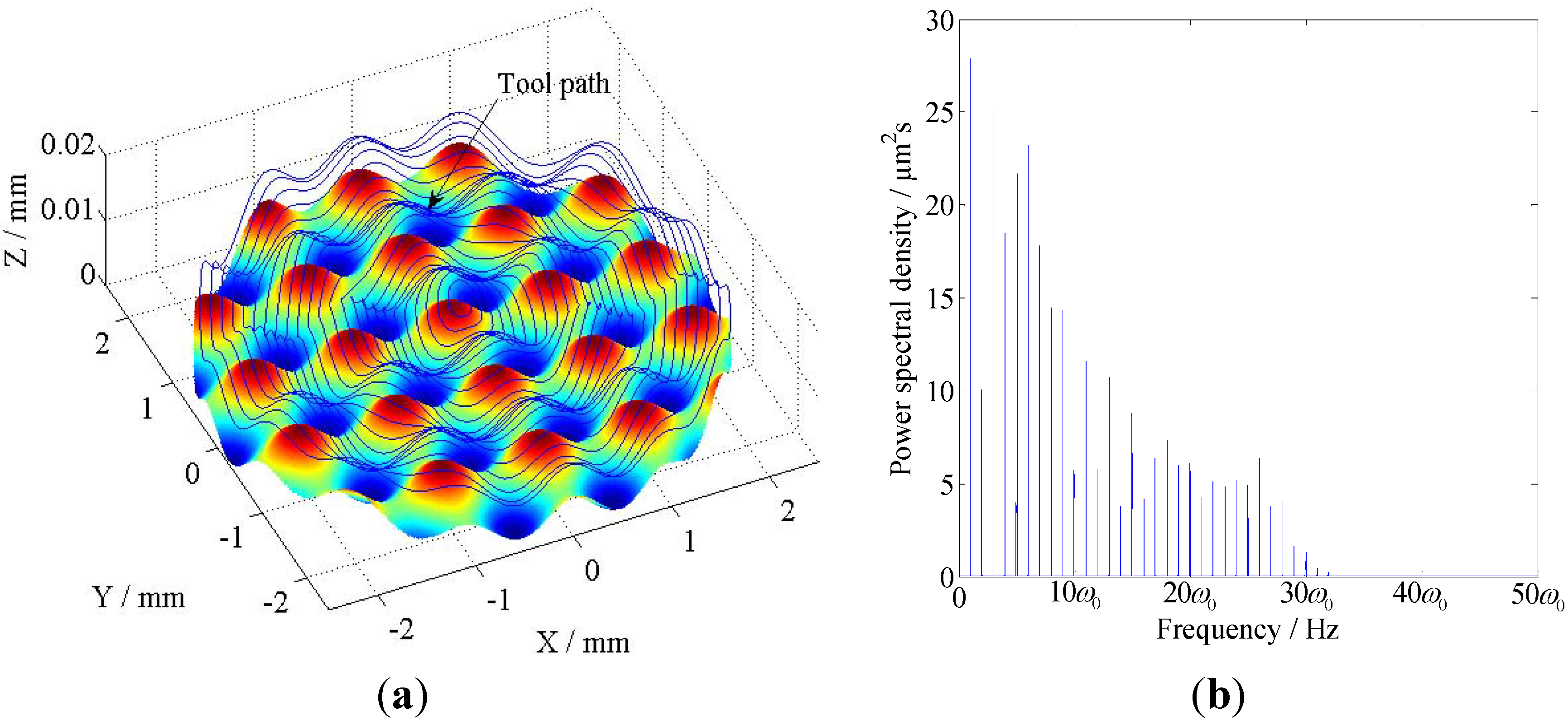
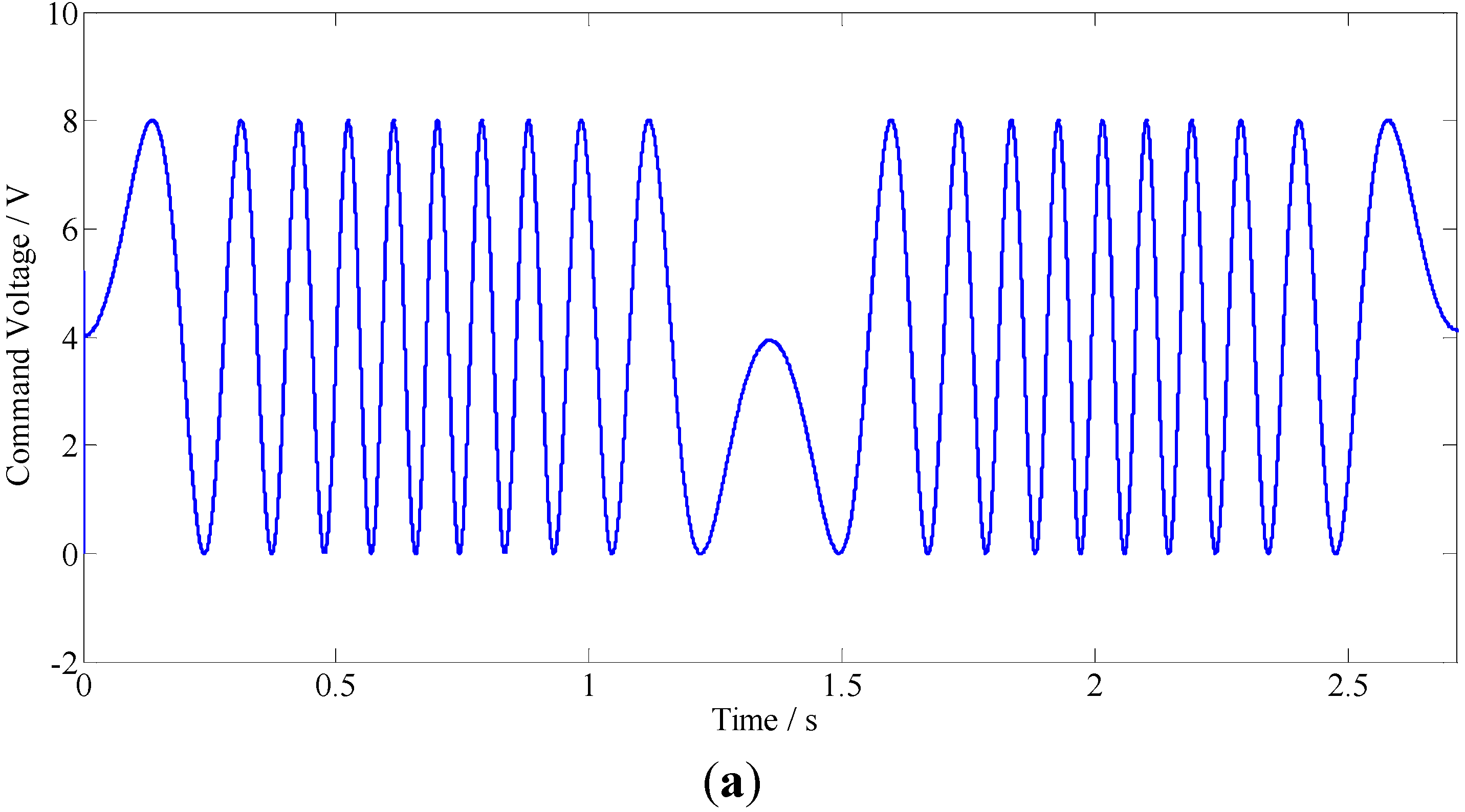
5.3.1. Case 1

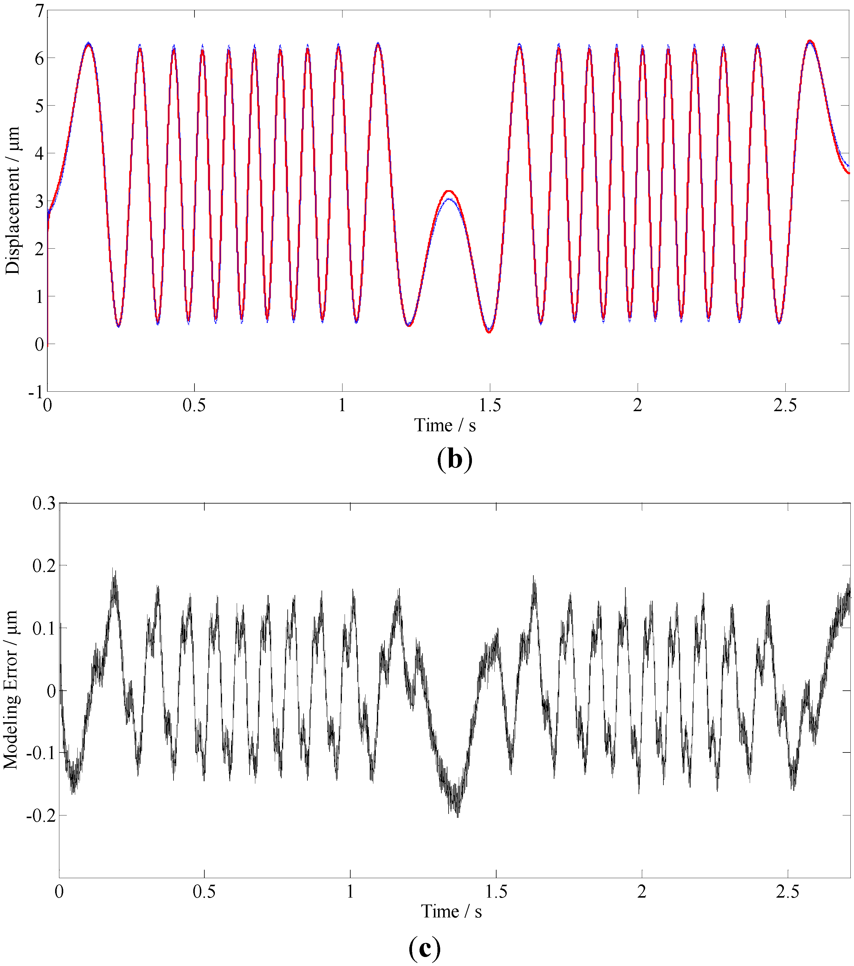
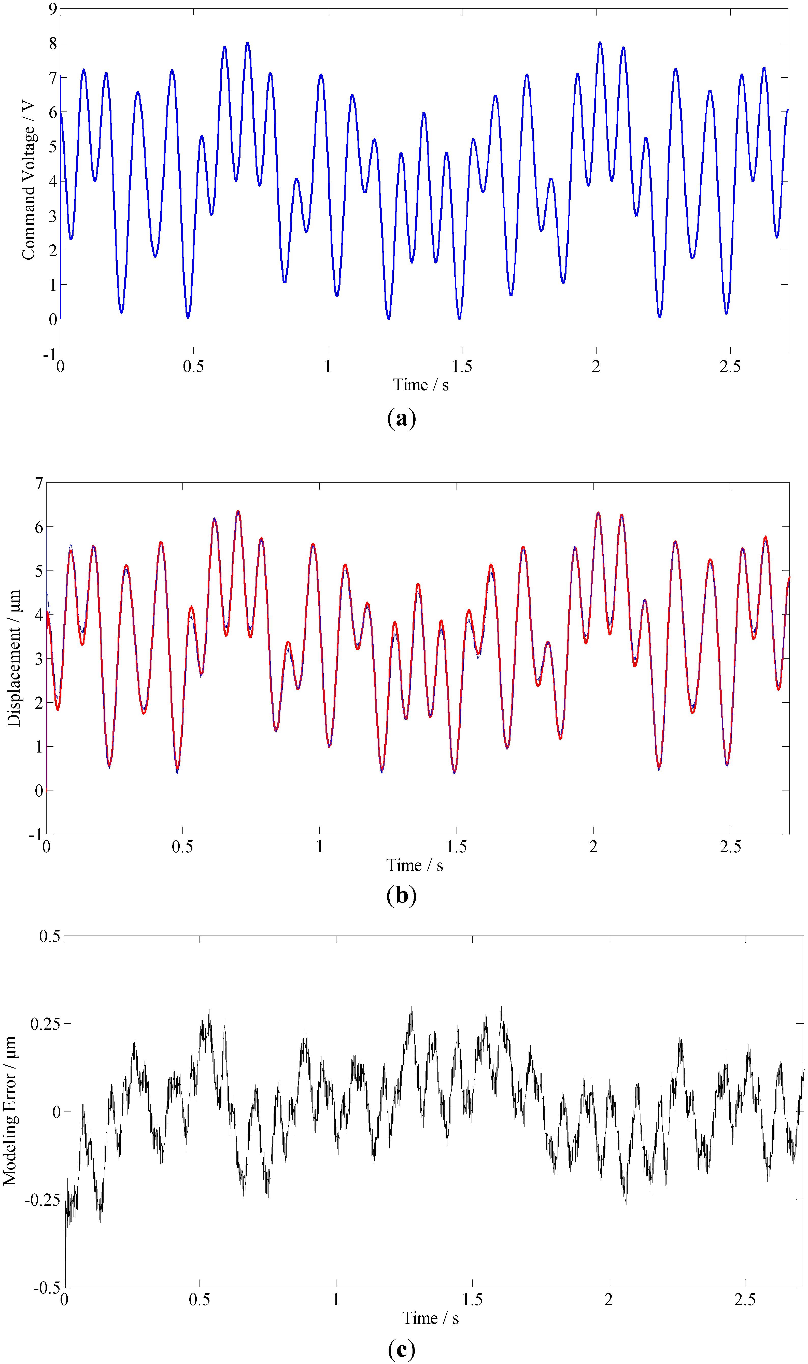
5.3.2. Case 2
5.4. Comparison with Certain State-of-the-Art Modeling Methods
| Model | Error |
|---|---|
| LFDH | ±2.5% |
| GPI | ±5.7% |
| DPM | 6.4% |
| DARMA.a | ±2.5% |
| DARMA.b | ±5.6% |
| NSBW.a | ±2.54% |
| NSBW.b | ±2.76% |
| BW.a | ±3.58% |
| BW.b | ±3.96% |

6. Conclusion
- Fractional order calculus (FOC) theory is introduced to establish a model for dynamic hysteresis nonlinearities, a fictitious hysteresis force is introduced and mathematically described by a fractional order differential equation. The hysteresis force model (HFM) can be characterized by nonlinear phase-shifts and nonlinear modulations of amplitudes, both mainly depending on input frequencies and differential orders. By choosing proper model parameters, the dynamic hysteresis effects could be well described.
- Combining the linear dynamics model of the FTS mechanism and the HFM, a linearized fractional order dynamic hysteresis (LFDH) model is proposed for the piezoelectrically actuated FTS system. The linearization feature of the LFDH model could make easier to implement the inverse dynamic control, and give an excellent playground for the well-developed linear control theories. Besides, certain accurate model assisted state-of-the-art control or compensation strategies for nonlinear systems would also be potential for implementing on the FTS systems.
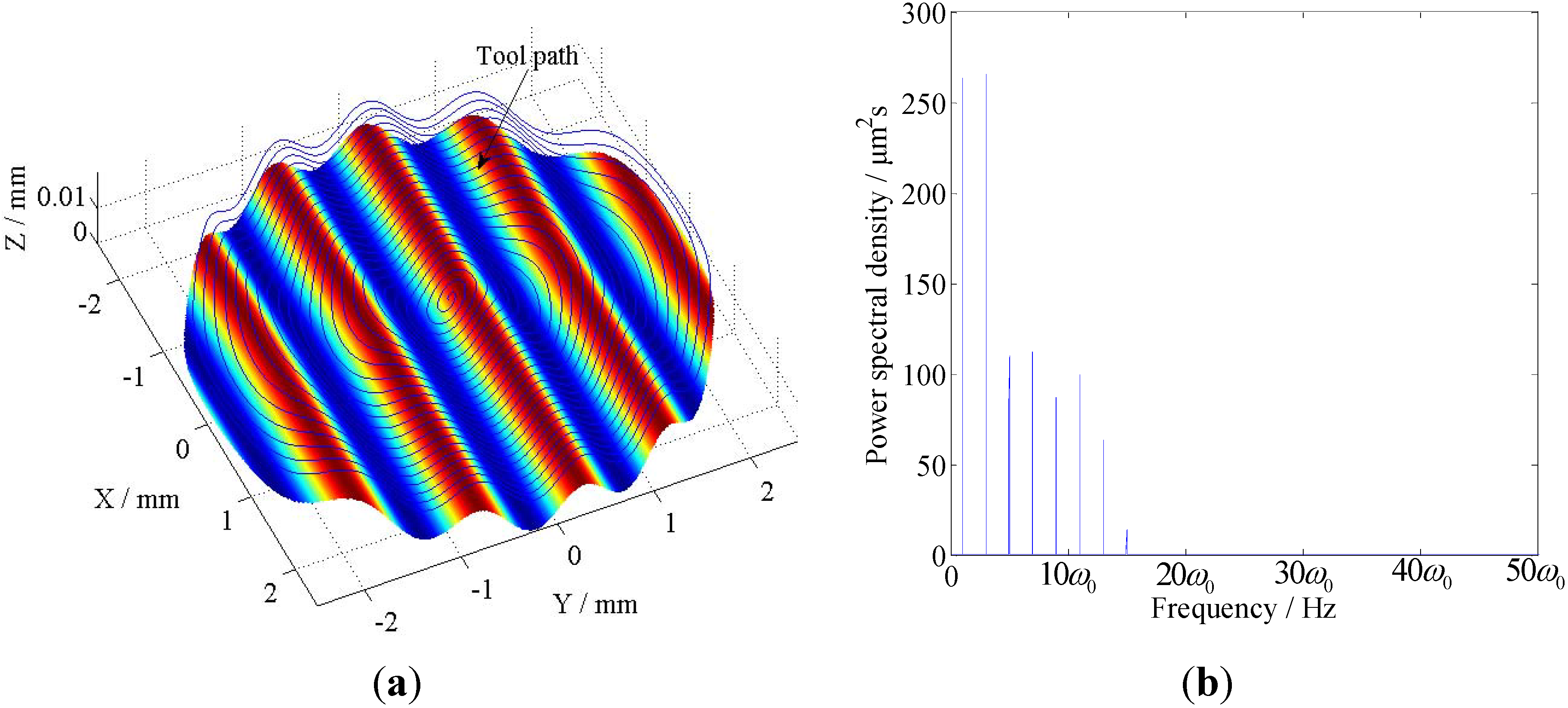
- To verify the efficiency of the LFDH model, the toolpath signals for creating two typical micro-functional surfaces, which cover a wide range of frequencies, are scaled and utilized as command signals for a piezoelectrically actuated FTS. By means of an evolutional scheme, the parameters of the model are estimated. The modeling errors in the steady state are all less than ±2.5% of the full span range, which is much smaller than the modeling errors of certain state-of-the-art modeling methods. The results demonstrate that the proposed linear model is of more excellent performance for modeling dynamic hysteresis nonlinearities, and the piezoelectrically actuated micro-systems would be more suitable to be described as a fractional order dynamic system.
- A more efficient parameter estimation method should be constructed to determine the best parameters of the LFDH model.
- The inverse model based hysteresis compensation approach should be further implemented with FTS to enhance the positioning accuracy of the cutting tool.
Acknowledgments
References
- Gao, W.; Araki, T.; Kiyono, S.; Okazaki, Y.; Yamanaka, M. Precision nano-fabrication and evaluation of a large area sinusoidal grid surface for a surface encoder. Precis. Eng. 2003, 27, 289–298. [Google Scholar] [CrossRef]
- Kim, H.S.; Lee, K.I.; Lee, K.M.; Bang, Y.B. Fabrication of free-form surfaces using a long-stroke fast tool servo and corrective figuring with on-machine measurement. Int. J. Mach. Tools Manuf. 2009, 49, 991–997. [Google Scholar] [CrossRef]
- Brinksmeier, E.; Riemer, O.; Gläbe, R.; Lünemann, B.; Kopylow, C.v.; Dankwart, C.; Meier, A. Submicron functional surfaces generated by diamond machining. CIRP Ann.-Manuf. Technol. 2010, 59, 535–538. [Google Scholar] [CrossRef]
- Yu, D.P.; Wong, Y.S.; Hong, G.S. Ultraprecision machining of micro-structured functional surfaces on brittle materials. J. Micromech. Microeng. 2011, 21. [Google Scholar] [CrossRef]
- Ru, C.; Sun, L. Improving positioning accuracy of piezoelectric actuators by feedforward hysteresis compensation based on a new mathematical model. Rev. Sci. Instrum. 2005, 76, 095111:1–095111:8. [Google Scholar] [CrossRef]
- Yeh, T.-J.; Ruo-Feng, H.; Shin-Wen, L. An integrated physical model that characterizes creep and hysteresis in piezoelectric actuators. Simul. Model. Pract. Theory 2008, 16, 93–110. [Google Scholar] [CrossRef]
- Wang, H.; Yang, S. Design and control of a fast tool servo used in noncircular piston turning process. Mech. Syst. Signal Process. 2011, in press. [Google Scholar]
- Liu, Q.; Zhou, X.; Xu, P.; Zou, Q.; Lin, C. A flexure-based long-stroke fast tool servo for diamond turning. Int. J. Adv. Manuf. Technol. 2012, 59, 859–867. [Google Scholar] [CrossRef]
- Byl, M.F.; Ludwick, S.J.; Trumper, D.L. A loop shaping perspective for tuning controllers with adaptive feedforward cancellation. Precis. Eng. 2005, 29, 27–40. [Google Scholar] [CrossRef]
- Yu, D.P.; Gan, S.W.; Wong, Y.S.; Hong, G.S.; Rahman, M.; Yao, J. Optimized tool path generation for fast tool servo diamond turning of micro-structured surfaces. Int. J. Adv. Manuf. Technol. 2012, 63, 1137–1152. [Google Scholar] [CrossRef]
- Wang, X.; Sun, T.; Zhou, J. Identification of preisach model for a fast tool servo system using neural networks. In Proceedings of the IEEE International Symposium on Knowledge Acquisition and Modeling Workshop, Wuhan, China, 21–22 December 2008; IEEE Computer Society: Los Alamitos, CA, USA, 2008; pp. 232–234. [Google Scholar]
- Ting, Y.; Li, C.; Lin, C. Controller design for high-frequency cutting using a piezo-driven microstage. Precis. Eng. 2011, 35, 455–463. [Google Scholar] [CrossRef]
- Adriaens, H.; De Koning, W.L.; Banning, R. Modeling piezoelectric actuators. IEEE-ASME Trans. Mechatron. 2000, 5, 331–341. [Google Scholar] [CrossRef]
- Shan, Y.F.; Leang, K.K. Accounting for hysteresis in repetitive control design: Nanopositioning example. Automatica 2012, 48, 1751–1758. [Google Scholar] [CrossRef]
- Leang, K.K.; Devasia, S. Feedback-linearized inverse feedforward for creep, hysteresis, and vibration compensation in AFM piezoactuators. IEEE Trans. Control Syst. Technol. 2007, 15, 927–935. [Google Scholar] [CrossRef]
- Croft, D.; Shed, G.; Devasia, S. Creep, hysteresis, and vibration compensation for piezoactuators: Atomic force microscopy application. J. Dyn. Sys. Meas. Control 2001, 123, 35–43. [Google Scholar] [CrossRef]
- Rakotondrabe, M.; Clévy, C.; Lutz, P. Complete open loop control of hysteretic, creeped, and oscillating piezoelectric cantilevers. IEEE Trans. Autom. Sci. Eng. 2010, 7, 440–450. [Google Scholar] [CrossRef] [Green Version]
- Tan, U.; Latt, W.T.; Widjaja, F.; Shee, C.Y.; Riviere, C.N.; Ang, W.T. Tracking control of hysteretic piezoelectric actuator using adaptive rate-dependent controller. Sensor. Actuator. A- Phys. 2009, 150, 116–123. [Google Scholar] [CrossRef]
- Devasia, S.; Eleftheriou, E.; Moheimani, S.O.R. A survey of control issues in nanopositioning. IEEE Trans. Control Syst. Technol. 2007, 15, 802–823. [Google Scholar] [CrossRef]
- Nguyen, P.B.; Choi, S.B. Micro-position control of a piezostack actuator using rate-dependent hysteretic compensator. Int. J. Precis. Eng. Manuf. 2011, 12, 885–891. [Google Scholar] [CrossRef]
- Hu, H.; Georgiou, H.; Ben-Mrad, R. Enhancement of tracking ability in piezoceramic actuators subject to dynamic excitation conditions. IEEE-ASME Trans. Mechatron. 2005, 10, 230–239. [Google Scholar] [CrossRef]
- Mrad, R.B.; Hu, H. A model for voltage-to-displacement dynamics in piezoceramic actuators subject to dynamic-voltage excitations. IEEE-ASME Trans. Mechatron. 2002, 7, 479–489. [Google Scholar] [CrossRef]
- Mrad, R.B.; Hu, H. Dynamic modeling of hysteresis in piezoceramics. In Proceedings of the 2001 IEEE/ASME International Conference on Advanced Intelligent Mechatronics, Como, Italy, 8–12 July 2001; IEEE Computer Society: Los Alamitos, CA, USA, 2001; pp. 510–515. [Google Scholar]
- Yu, Y.; Xiao, Z.; Naganathan, N.G.; Dukkipati, R.V. Dynamic Preisach modelling of hysteresis for the piezoceramic actuator system. Mech. Mach. Theor. 2002, 37, 75–89. [Google Scholar] [CrossRef]
- Ang, W.T.; Khosla, P.K.; Riviere, C.N. Feedforward controller with inverse rate-dependent model for piezoelectric actuators in trajectory-tracking applications. IEEE-ASME Trans. Mechatron. 2007, 12, 134–142. [Google Scholar] [CrossRef]
- Ang, W.T.; Garmon, F.A.; Khosla, P.K.; Riviere, C.N. Modeling rate-dependent hysteresis in piezoelectric actuators. In Proceedings of the 2003 IEEE/RSJ International Conference on Intelligent Robots and Systems (IROS 2003), New York, NJ, USA, 27–31 October 2003; IEEE Computer Society: Los Alamitos, CA, USA, 2003; Volume 2, pp. 1975–1980. [Google Scholar]
- Al Janaideh, M.; Su, C.Y.; Rakheja, S. Development of the rate-dependent Prandtl–Ishlinskii model for smart actuators. Smart Mater. Struct. 2008, 17. [Google Scholar] [CrossRef]
- Al Janaideh, M.; Rakheja, S.; Su, C.Y. An analytical generalized Prandtl–Ishlinskii model inversion for hysteresis compensation in micropositioning control. IEEE-ASME Trans. Mechatron. 2011, 16, 734–744. [Google Scholar]
- Janaideh, M.A.; Rakheja, S.; Su, C.Y. Experimental characterization and modeling of rate-dependent hysteresis of a piezoceramic actuator. Mechatronics 2009, 19, 656–670. [Google Scholar] [CrossRef]
- Dong, R.; Tan, Y.; Chen, H.; Xie, Y. A neural networks based model for rate-dependent hysteresis for piezoceramic actuators. Sensor. Actuator. A-Phys. 2008, 143, 370–376. [Google Scholar] [CrossRef]
- Zhang, X.; Tan, Y. A hybrid model for rate-dependent hysteresis in piezoelectric actuators. Sensor. Actuator. A-Phys. 2010, 157, 54–60. [Google Scholar] [CrossRef]
- Wong, P.K.; Xu, Q.; Vong, C.M.; Wong, H.C. Rate-dependent hysteresis modeling and control of a piezostage using online support vector machine and relevance vector machine. IEEE Trans. Ind. Electron. 2012, 59, 1988–2001. [Google Scholar] [CrossRef]
- Deng, L.; Tan, Y. Modeling hysteresis in piezoelectric actuators using NARMAX models. Sensor. Actuator. A-Phys. 2009, 149, 106–112. [Google Scholar] [CrossRef]
- Rakotondrabe, M.; Haddab, Y.; Lutz, P. Quadrilateral modelling and robust control of a nonlinear piezoelectric cantilever. IEEE Trans. Control Syst. Techn. 2009, 17, 528–539. [Google Scholar] [CrossRef] [Green Version]
- Gu, G.Y.; Zhu, L.M. Modeling of rate-dependent hysteresis in piezoelectric actuators using a family of ellipses. Sensor. Actuator. A-Phys. 2011, 165, 303–309. [Google Scholar] [CrossRef]
- Gu, G.Y.; Zhu, L.M. High-speed tracking control of piezoelectric actuators using an ellipse-based hysteresis model. Rev. Sci. Instrum. 2010, 81, 085104:1–085104:9. [Google Scholar]
- Machado, J.T.; Kiryakova, V.; Mainardi, F. Recent history of fractional calculus. Commun. Nonlinear Sci. Numer. Simul. 2011, 16, 1140–1153. [Google Scholar] [CrossRef]
- Monje, C.A.; Chen, Y.Q.; Vinagre, B.M.; Xue, D.; Feliu, V. Fractional-Order Systems and Controls: Fundamentals and Applications; Springer: London, UK, 2010. [Google Scholar]
- Rossikhin, Y.A.; Shitikova, M.V. Application of fractional calculus for dynamic problems of solid mechanics: Novel trends and recent results. Appl. Mech. Rev. 2010, 63, 010801:1–010801:52. [Google Scholar]
- Chen, Y.Q.; Petras, I.; Xue, D. Fractional Order Contro—A Tutorial. In Proceedings of the American Control Conference, 2009 (ACC’09), St. Louis, MO, USA, 10–12 June 2009; IEEE Computer Society: Los Alamitos, CA, USA, 2009; pp. 1397–1411. [Google Scholar]
- Meral, F.; Royston, T.; Magin, R. Fractional calculus in viscoelasticity: an experimental study. Commun. Nonlinear Sci. Numer. Simul. 2010, 15, 939–945. [Google Scholar] [CrossRef]
- de Espı́ndola, J.; da Silva Neto, J.M.; Lopes, E.M.O. A generalised fractional derivative approach to viscoelastic material properties measurement. Appl. Math. Comput. 2005, 164, 493–506. [Google Scholar]
- Sunny, M.R.; Kapania, R.K.; Moffitt, R.D.; Mishra, A.; Goulbourne, N. A Modified Fractional Calculus Approach to Model Hysteresis. J. Appl. Mech. 2010, 77, 031004:1–031004:8. [Google Scholar] [CrossRef]
- Guyomar, D.; Ducharne, B.; Sebald, G. The use of fractional derivation in modeling ferroelectric dynamic hysteresis behavior over large frequency bandwidth. J. Appl. Phys. 2010, 107, 114108:1–114108:6. [Google Scholar] [CrossRef]
- Guyomar, D.; Ducharne, B.; Sebald, G. High frequency bandwidth polarization and strain control using a fractional derivative inverse model. Smart Mater. Struct. 2010, 19. [Google Scholar] [CrossRef]
- Tavazoei, M.S. A note on fractional-order derivatives of periodic functions. Automatica 2010, 46, 945–948. [Google Scholar] [CrossRef]
- Podlubny, I. Fractional Differential Equations; Academic Press: San Diego, CA, USA, 1999. [Google Scholar]
- Matignon, D. Stability Properties for Generalized Fractional Differential Systems. In Proceedings of the Mathematics Theory of Networks and Systems Symposium, Padova, Italy, 6–10 July 1998; EDP Sciences: Paris, France, 1998; pp. 145–158. [Google Scholar]
- Tian, Y.; Shirinzadeh, B.; Zhang, D. A flexure-based mechanism and control methodology for ultra-precision turning operation. Precis. Eng. 2009, 33, 160–166. [Google Scholar] [CrossRef]
- Zhou, X.; Zhu, Z.; Zhao, S.; Luo, D. A Novel Hybrid Control Strategy for Trajectory Tracking of Fast Tool Servo. In Proceedings of the 2010 2nd International Conference on Mechanical and Electronics Engineering (ICMEE), Kyoto, Japan, 1–3 August 2010; IEEE Computer Society: Los Alamitos, CA, USA, 2010; Volume 2, pp. 325–328. [Google Scholar]
- Tian, Y.; Zhang, D.; Shirinzadeh, B. Dynamic modelling of a flexure-based mechanism for ultra-precision grinding operation. Precis. Eng. 2011, 35, 554–565. [Google Scholar] [CrossRef]
- Lee, C.; Itoh, T.; Suga, T. Self-excited piezoelectric PZT microcantilevers for dynamic SFM-with inherent sensing and actuating capabilities. Sensor. Actuator. A-Phys. 1999, 72, 179–188. [Google Scholar] [CrossRef]
- Zhu, Z.; Zhou, X.; Liu, Q.; Lin, J.; Zhao, S. Fabrication of micro-structured surfaces on bulk metallic glasses based on fast tool servo assisted diamond turning. Sci. Adv. Mater. 2012, 4, 906–911. [Google Scholar] [CrossRef]
- Cuttino, J.F.; Miller, A.C., Jr.; Schinstock, D.E. Performance optimization of a fast tool servo for single-point diamond turning machines. IEEE-ASME Trans. Mechatron. 1999, 4, 169–179. [Google Scholar] [CrossRef]
- Rakuff, S.; Cuttino, J.F. Design and testing of a long-range, precision fast tool servo system for diamond turning. Precis. Eng. 2009, 33, 18–25. [Google Scholar] [CrossRef]
- Cruz-Hernández, J.M.; Hayward, V. Phase control approach to hysteresis reduction. IEEE Trans. Control Syst. Technol. 2001, 9, 17–26. [Google Scholar] [CrossRef]
- Zhu, Z.; Zhou, X.; Liu, Q.; Zhao, S. Multi-objective optimum design of fast tool servo based on improved differential evolution algorithm. J. Mech. Sci. Technol. 2011, 25, 3141–3149. [Google Scholar] [CrossRef]
- Zhang, X.D.; Fang, F.Z.; Wang, H.B.; Wei, G.S.; Hu, X.T. Ultra-precision machining of sinusoidal surfaces using the cylindrical coordinate method. J. Micromech. Microeng. 2009, 19. [Google Scholar] [CrossRef]
- Kao, C.C.; Fung, R.F. Using the modified PSO method to identify a Scott-Russell mechanism actuated by a piezoelectric element. Mech. Syst. Signal Process. 2009, 23, 1652–1661. [Google Scholar] [CrossRef]
- Brest, J.; Greiner, S.; Boskovic, B.; Mernik, M.; Zumer, V. Self-adapting control parameters in differential evolution: A comparative study on numerical benchmark problems. IEEE Trans. Evol. Computat. 2006, 10, 646–657. [Google Scholar] [CrossRef]
- Cao, Y.; Chen, X. A novel discrete ARMA-based model for piezoelectric actuator hysteresis. IEEE-ASME Trans. Mechatron. 2012, 17, 737–744. [Google Scholar] [CrossRef]
- Zhu, W.; Wang, D. Non-symmetrical Bouc-Wen model for piezoelectric ceramic actuators. Sensor. Actuator. A-Phys. 2012, 181, 51–60. [Google Scholar] [CrossRef]
© 2012 by the authors; licensee MDPI, Basel, Switzerland. This article is an open access article distributed under the terms and conditions of the Creative Commons Attribution license (http://creativecommons.org/licenses/by/3.0/).
Share and Cite
Zhu, Z.; Zhou, X. A Novel Fractional Order Model for the Dynamic Hysteresis of Piezoelectrically Actuated Fast Tool Servo. Materials 2012, 5, 2465-2485. https://doi.org/10.3390/ma5122465
Zhu Z, Zhou X. A Novel Fractional Order Model for the Dynamic Hysteresis of Piezoelectrically Actuated Fast Tool Servo. Materials. 2012; 5(12):2465-2485. https://doi.org/10.3390/ma5122465
Chicago/Turabian StyleZhu, Zhiwei, and Xiaoqin Zhou. 2012. "A Novel Fractional Order Model for the Dynamic Hysteresis of Piezoelectrically Actuated Fast Tool Servo" Materials 5, no. 12: 2465-2485. https://doi.org/10.3390/ma5122465