Shear Behavior Models of Steel Fiber Reinforced Concrete Beams Modifying Softened Truss Model Approaches

 ,
,
Abstract
:1. Introduction
2. Review of Previous Research
2.1. Shear Strength Models

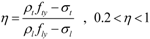
 ) is obtained from a direct tensile test, 2/3 if from a splitting tensile test, and 4/9 if from a flexural tensile test. If Equation (1) is used without tensile tests, 2/3 and
  are used for k and , respectively. In addition, d is the effective member depth; and a is the shear span length. Equation (1) has been used since ACI Committee 544 adopted it in 1988 [1].


 ). In Equation (5), νb is an additional shear resistance by steel fibers in the deep SFRC members, which was recommended as 1.7(lf/df)·Vf·ρf based on the Swamy et al.’s research [20].

2.2. Shear Behavior Models

3. Modified Shear Behavior Models Based on the Softened Truss Models
3.1. Rotating Angle Softened Truss Model (RA-STM)
3.2. Fixed Angle Softened Truss Model (FA-STM)
3.3. Smeared Membrane Model (SMM)
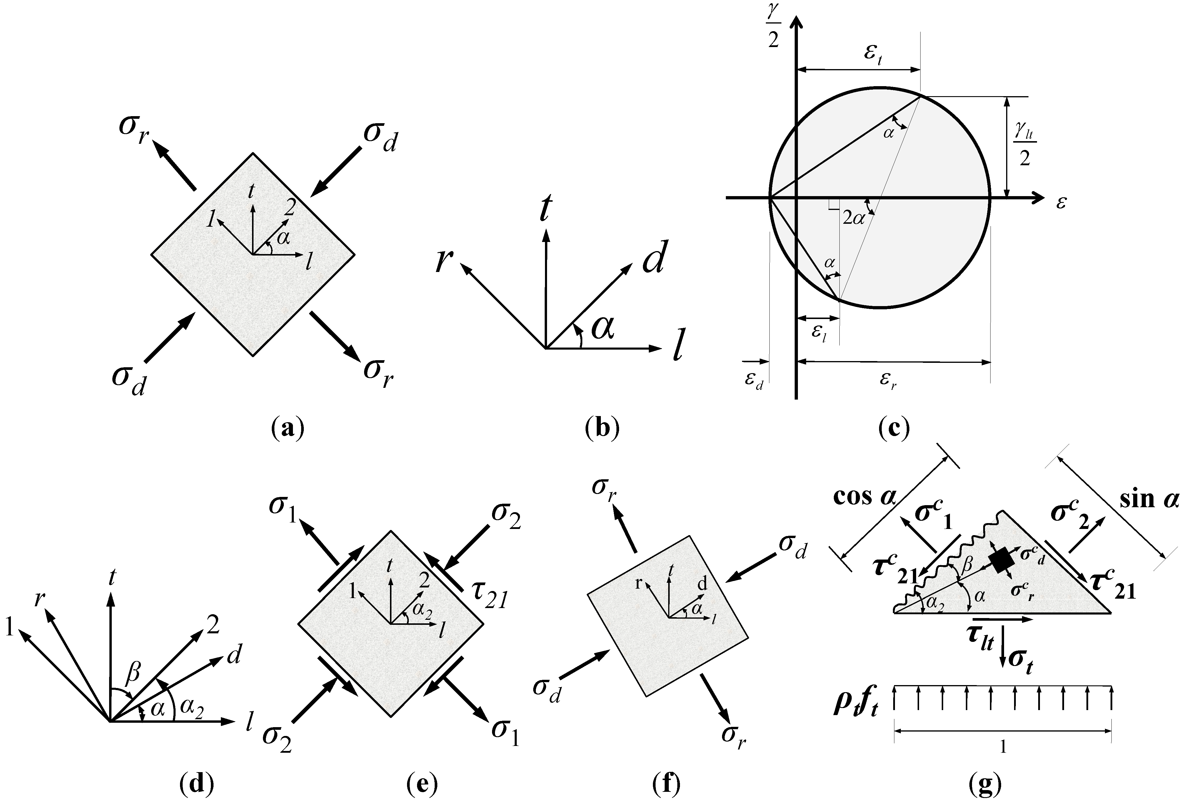
3.4. Transformation Angle Truss Model (TATM)
4. Proposed Model: Softened Truss Model with Steel Fibers (STM-SF)


 ,
,  , and
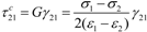
, and  are the average stresses of steel fibers in the longitudinal direction, in the transverse direction, and in the crack direction, respectively. Thus, the final forms of the equilibrium equations for SFRC members can be obtained by adding Equations (8)–(10) to the equilibrium equations of RA-STM, FA-STM, SMM, and TATM in the longitudinal and transverse directions.) of the steel fibers on the crack plane can be expressed by dividing the tensile force (Tf) by the area of the crack surface (Acs), as follows:

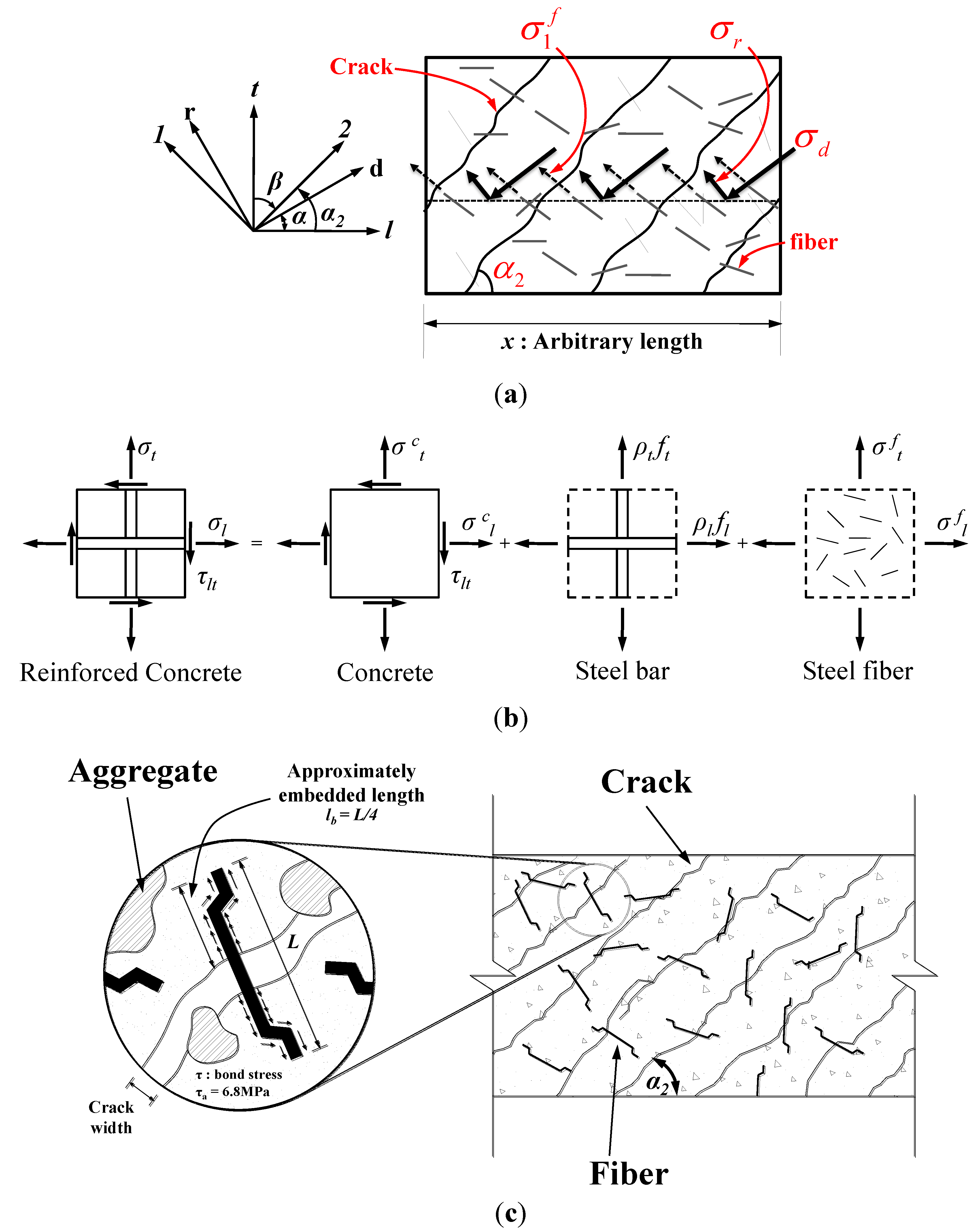
 ) of the steel fibers on the crack surface can be rearranged as follows:
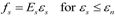
 ) reaches its maximum bond stress, the pullout failure of the steel fibers would occur. Thus, the maximum value of the fiber stress ( ) should be limited to the maximum bond stress (τmax), and accordingly, the pullout strength (σfp) of steel fibers can be derived as follows:


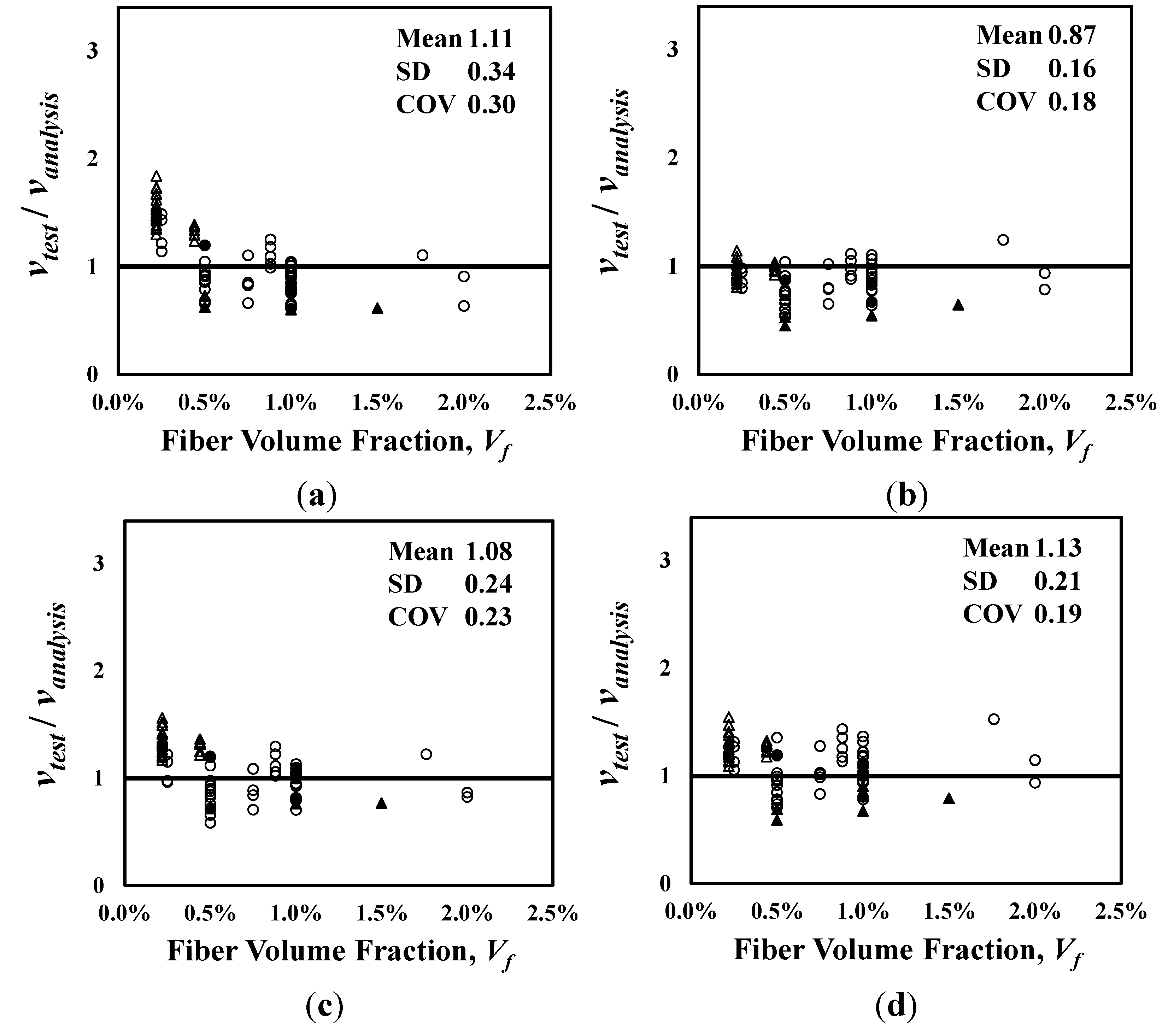
5. Evaluation of the Proposed Models
) also ranged widely from 20.6 to 93.8 MPa, including normal-strength concrete and high-strength concrete. All the specimens that were used for the evaluation did not have shear reinforcements, and the tensile steel ratio (ρs) ranged from 1.1% to 5.7%.
| Reference No. | Number of specimens | shape | Vf (%) | L (mm) | D (mm) | (MPa) | d (mm) | a/d | ρs (%) |
|---|---|---|---|---|---|---|---|---|---|
| [16] | 13 | round | 0.22–0.44 | 25.4 | 0.25 | 33.2–40.2 | 127 | 4.0–4.8 | 1.96 |
| 24 | crimped | 0.22–1.76 | 25.4 | 0.25 × 5.6 * 0.38 × 0.63* 0.41 × 0.25* | 33.2–40.2 | 127 | 4.0–4.8 | 1.96 | |
| [10] | 18 | crimped | 0.25–1.0 | 30–40 | 0.3 | 29.9–59.6 | 126–130 | 2.5–3.5 | 2.00–5.72 |
| [2] | 7 | hooked | 0.5–1.0 | 30 | 0.5 | 20.6–33.4 | 197 | 2.8–3.6 | 1.34–2.00 |
| [25] | 5 | hooked | 0.5–1.0 | 30 | 0.5 | 34 | 221 | 2.5–3.5 | 1.10–2.20 |
| [8] | 5 | hooked | 0.5–1.5 | 60 | 0.8 | 93.8–97.1 | 215 | 4.0–6.0 | 2.84–4.58 |
| [41] | 5 | hooked | 1.0 | 30–50 | 0.5 | 22.7–26 | 102–204 | 3.0 | 1.10–2.20 |
| [42] | 4 | crimped | 0.5–2.0 | 25.4–38.1 | 0.2 × 2.3* | 49.3–54.8 | 80 | 3.75 | 1.77 |
| [43] | 2 | round | 1.0–2.0 | 42 | 0.7 | 38.7–42.4 | 150 | 2.67 | 2.65 |
| [44] | 2 | hooked | 1.0–2.0 | 30 | 0.5 | 40.9–43.2 | 219 | 2.8 | 1.74 |
| Total | 85 | round, crimped, hooked | 0.22–2.0 | 25.4–60 | 0.25–0.8 | 20.6–97.1 | 80–221 | 2.5–6.0 | 1.10–5.72 |
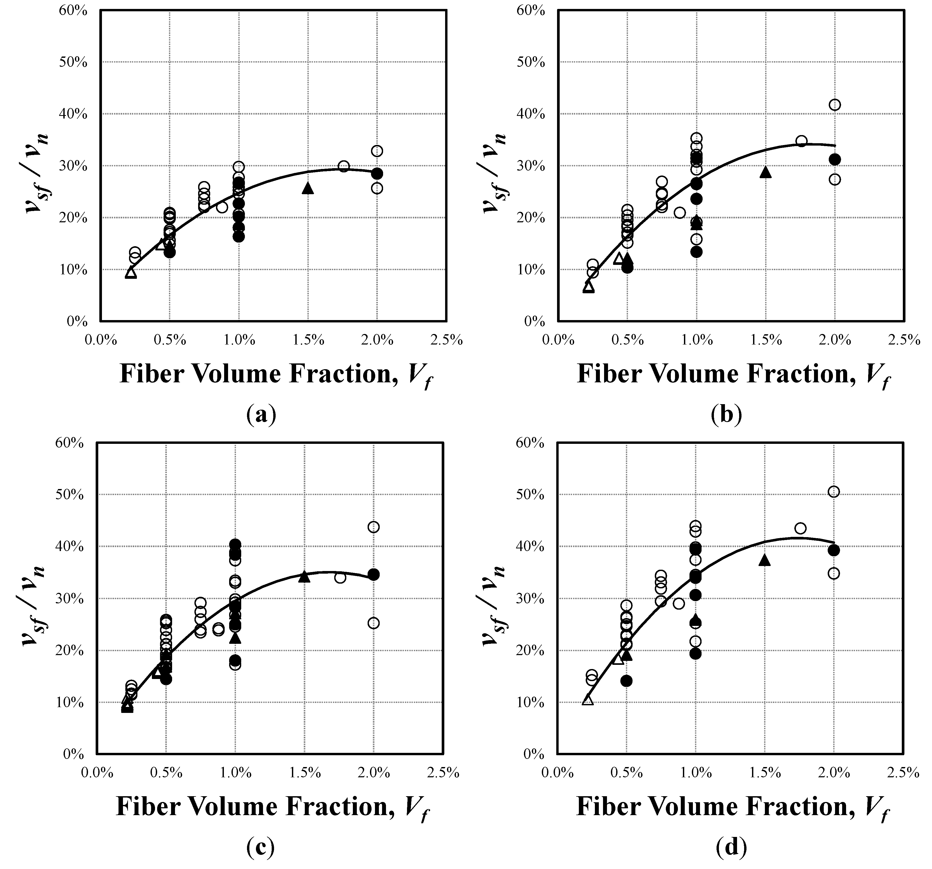
≥ 50 MPa, a/d < 4; ○: < 50 MPa, a/d < 4; ▲: ≥ 50 MPa, a/d ≥ 4; △: < 50 MPa, a/d ≥ 4.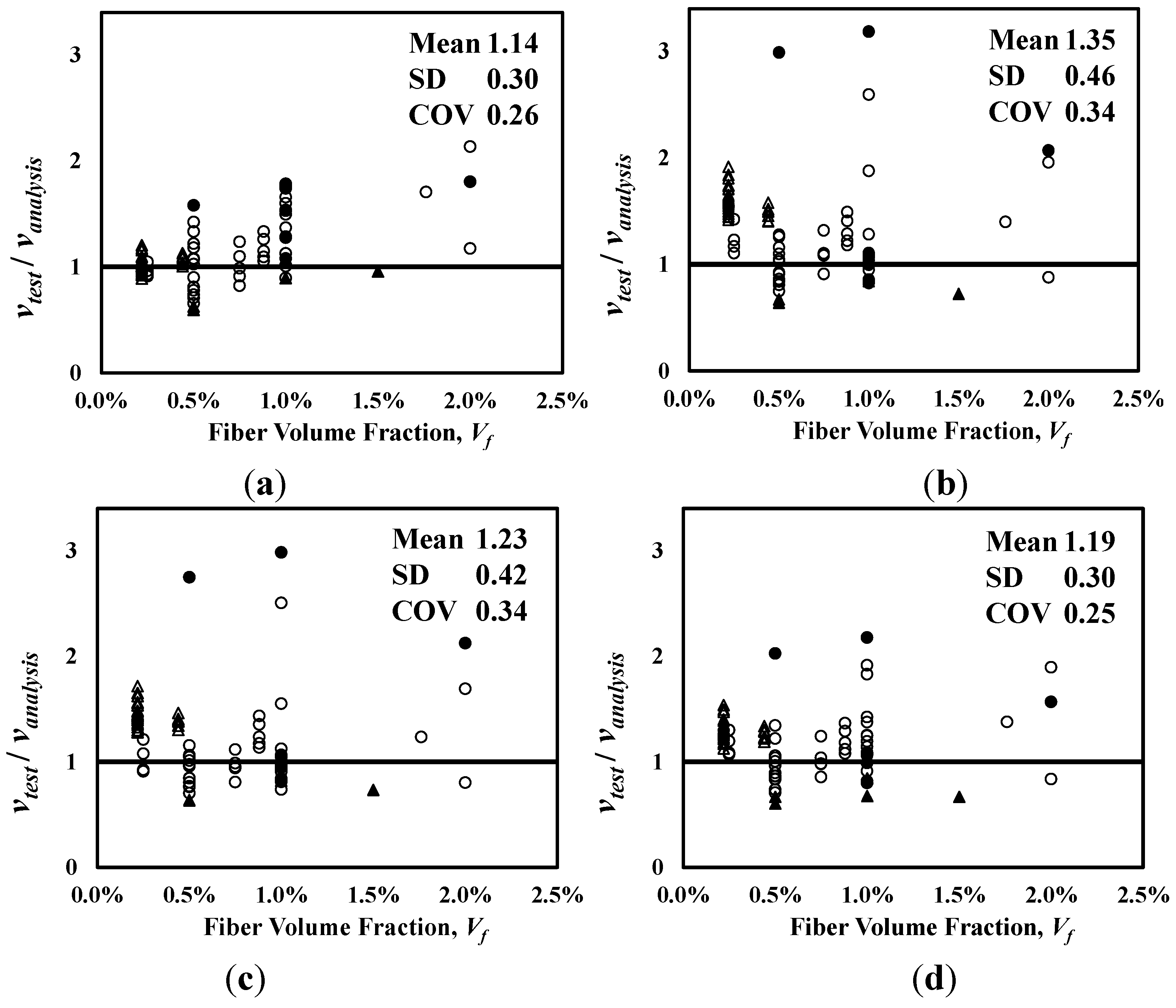
| Model | RA-STM with steel fiber | FA-STM with steel fiber | TATM with steel fiber | SMM with steel fiber |
|---|---|---|---|---|
| Mean | 1.112 | 0.871 | 1.082 | 1.131 |
| SD | 0.338 | 0.157 | 0.244 | 0.213 |
| COV | 0.304 | 0.181 | 0.225 | 0.188 |
| Author | Sharma (ACI) [9] | Narayanan et al. [10] | Kwak et al. [11] | Oh et al. [12] |
| Mean | 1.143 | 1.345 | 1.229 | 1.188 |
| SD | 0.298 | 0.456 | 0.419 | 0.296 |
| COV | 0.261 | 0.339 | 0.341 | 0.249 |
≥ 50 MPa, a/d < 4; ○: < 50 MPa, a/d < 4; ▲: ≥ 50 MPa, a/d ≥ 4; △: < 50 MPa, a/d ≥ 4.
≥ 50 MPa, a/d < 4; ○: < 50 MPa, a/d < 4; ▲: ≥ 50 MPa, a/d ≥ 4; △: < 50 MPa, a/d ≥ 4.
 ≥ 50 MPa, a/d < 4; ○: < 50 MPa, a/d < 4; ▲: ≥ 50 MPa, a/d ≥ 4; △: < 50 MPa, a/d ≥ 4.
≥ 50 MPa, a/d < 4; ○: < 50 MPa, a/d < 4; ▲: ≥ 50 MPa, a/d ≥ 4; △: < 50 MPa, a/d ≥ 4.
≥ 50 MPa, a/d < 4; ○: < 50 MPa, a/d < 4; ▲: ≥ 50 MPa, a/d ≥ 4; △: < 50 MPa, a/d ≥ 4.
6. Conclusions
- The softened truss models were modified to be suitable for the analysis of SFRC members by modeling steel fibers as independent tensile elements, which, in particular, can estimate the stresses of steel fibers according to the detailed characteristics of the steel fibers.
- All the STM-SF models proposed in this study, except for the modified RA-STM with steel fibers, showed a good level of accuracy on the shear strength of SFRC members compared to the empirical equations presented in previous studies.
- The proposed models adequately simulated the pullout failure of steel fibers, which is the characteristic failure mode in SFRC members, based on the average ultimate bond strength of steel fibers.
- The modeling method, applying the stress of fibers perpendicular to crack direction directly, was considered more appropriate in FASTM than RASTM; it is, because, as expected, the fixed angle model could reflect the stress of fibers at crack more accurately.
- The contribution ratios of steel fibers on the shear strength of SFRC members were calculated by the proposed models, which was found to be approximately 30% at the 1%–1.5% steel fiber volume fraction.
- Based on the observations of the shear contribution ratio of steel fibers, the optimal range of the steel fiber volume fraction, in terms of shear performance, is 1%–1.5%.
Acknowledgments
Conflicts of Interest
Appendix
| Model | RA-STM | FA-STM | ||
|---|---|---|---|---|
| Equilibrium equations |  | (A-1a) |  | (A-6a) |
 | (A-1b) |  | (A-6b) | |
 | (A-1c) |  | (A-6c) | |
| Comparability equations |  | (A-2a) |  | (A-7a) |
 | (A-2b) |  | (A-7b) | |
 | (A-2c) |  | (A-7c) | |
| Constitutive equations | Concrete compression | Concrete compression | ||
 | (A-3a) |  | (A-3a) | |
 | (A-3b) |  | (A-3d) | |
 | (A-3c) |  | (A-3e) | |
| Concrete tension |  | (A-3f) | ||
 | (A-4a) | Concrete tension | ||
 | (A-4b) |  | (A-4a) | |
| Mild steel |  | (A-4b) | ||
 | (A-5a) | Mild steel | ||
 | (A-5b) |  | (A-5a) | |
 | (A-5c) |  | (A-5b) | |
 | (A-5d) |  | (A-5c) | |
 | (A-5d) | |||
| Shear stress of concrete at crack | ||||
 | (A-8) | |||
| Model | SMM | TATM | ||
|---|---|---|---|---|
| Equilibrium equations |  | (A-6a) | ||
 | (A-6b) | |||
 | (A-6a) |  | (A-6c) | |
 | (A-6b) |  | (A-9a) | |
 | (A-6c) |  | (A-9b) | |
 | (A-9c) | |||
| Comparability equations |  | (A-14a) | ||
 | (A-14b) |  | (A-7a) | |
 | (A-14c) |  | (A-7b) | |
 | (A-14d) |  | (A-7c) | |
 | (A-7c) | |||
| Constitutive equations | Concrete compression | Concrete compression | ||
 | (A-3a) |  | (A-10a) | |
 | (A-3d) |  | (A-10b) | |
 | (A-3e) | Concrete tension | ||
 | (A-11a) | |||
 | (A-3f) |  | (A-11b) | |
| Concrete tension | Steel | |||
 | (A-4a) |  | (A-12a) | |
 | (A-4b) |  | (A-12b) | |
| Mild steel | Shear stress of concrete at crack | |||
 | (A-5a) |  | (A-13a) | |
 | (A-5b) |  | (A-13b) | |
 | (A-5c) |  | (A-13c) | |
 | (A-5d) |  | (A-13d) | |
| Shear stress of concrete at crack |  | (A-13e) | ||
 | (A-8) | |||
References
- American Concrete Institute Committee 544. Design Consideration for Steel Fiber Reinforced Concrete (ACI 544.4R-88); American Concrete Institute: Farmington Hills, MI, USA, 1988; pp. 563–580. [Google Scholar]
- Mansur, M.A.; Ong, K.C.G.; Paramsivam, P. Shear strength of fibrous concrete beams without stirrups. J. Struct. Eng. 1986, 112, 2066–2079. [Google Scholar] [CrossRef]
- Khuntia, M.; Stojadinonic, B.; Goel, S.C. Shear strength of normal and high-strength fiber reinforced concrete beams without stirrups. ACI Struct. J. 1999, 96, 282–289. [Google Scholar]
- Kim, K.S.; Lee, D.H.; Hwang, J.; Kuchma, D.A. Shear behavior model for steel fiber-reinforced concrete members without transverse reinforcements. Compos. Part B Eng. 2012, 43, 2324–2334. [Google Scholar] [CrossRef]
- Lee, D.H.; Hwang, J.H.; Ju, H.; Kim, K.S.; Kuchma, D.A. Nonlinear finite element analysis of steel fiber-reinforced concrete members using direct tension force transfer model. Finite Elem. Anal. Des. 2012, 50, 266–286. [Google Scholar] [CrossRef]
- Ju, H.; Lee, D.H.; Hwang, J.H.; Kang, J.W.; Kim, K.S.; Oh, Y.H. Torsional behavior model of steel fiber-reinforced concrete members modifying fixed-angle softened-truss model. Compos. Part B Eng. 2013, 45, 215–231. [Google Scholar] [CrossRef]
- Consiglio Nazionale delle Ricerche. Istruzioni per la Progettazione, l’Esecuzione ed il Controllo di Strutture di Calcestruzzo Fibrorinforzato (CNR-DT 204); (in Italian). Consiglio Nazionale delle Ricerche: Roma, Italy, 2006. [Google Scholar]
- Ashour, S.A.; Hassanain, G.S.; Wafa, F.F. Shear behavior of high-strength fiber reinforced concrete beams. ACI Struct. J. 1992, 89, 176–184. [Google Scholar]
- Sharma, A.K. Shear strength of steel fiber reinforced concrete beams. ACI J. Proc. 1986, 83, 624–628. [Google Scholar]
- Narayanan, R.; Darwish, I.Y. S. Use of steel fibers as shear reinforcement. ACI Struct. J. 1987, 84, 216–227. [Google Scholar]
- Kwak, Y.K.; Eberhard, M.O.; Kim, W.S.; Kim, J. Shear strength of steel fiber reinforced concrete beams without stirrups. ACI Struct. J. 2012, 99, 530–538. [Google Scholar]
- Oh, Y.H.; Kim, J.H. Estimation of flexural and shear strength for steel fiber reinforced flexural members without shear reinforcements. J. Korea Concr. Inst. 2008, 20, 257–267. [Google Scholar] [CrossRef]
- Dinh, H.H.; Parra-Montesinos, G.J.; Wight, J.K. Shear strength model for steel fiber reinforced concrete beams without stirrup reinforcement. J. Struct. Eng. 2011, 137, 1039–1051. [Google Scholar] [CrossRef]
- Slater, E.; Moni, M.; Alam, M.S. Predicting the shear strength of steel fiber reinforced concrete beams. Constr. Build. Mater. 2012, 26, 423–436. [Google Scholar] [CrossRef]
- Romualdi, J.P.; Mandel, J.A. Tensile strength of concrete affected by uniformly distributed and closely spaced short lengths of wire reinforcement. ACI J. Proc. 1964, 61, 657–671. [Google Scholar]
- Batson, G.; Jenkins, E.; Spatney, R. Steel fibers as shear reinforcement in beams. ACI J. Proc. 1972, 69, 640–644. [Google Scholar]
- Swamy, R.N.; Bahia, H.M. Influence of fiber reinforcement on dowel resistance to shear. ACI J. Proc. 1979, 76, 327–355. [Google Scholar]
- American Concrete Institute Committee 318. Building Code Requirements for Reinforced Concrete and Commentary (ACI 318-11); American Concrete Institute: Farmington Hills, MI, USA, 2011; p. 503. [Google Scholar]
- Zsutty, T. Beam shear strength prediction by analysis of existing data. ACI J. Proc. 1968, 65, 943–951. [Google Scholar]
- Swamy, R.N.; Mangat, P.S.; Rao, C.V. Mechanics of Fiber Reinforcemen. In Fiber Reinforced Concrete; American Concrete Institute: Farmington Hills, MI, USA, 1974; pp. 1–28. [Google Scholar]
- Tan, K.H.; Mansur, M.A. Shear transfer in reinforced fiber concrete. J. Mater. Civ. Eng. 1990, 2, 202–214. [Google Scholar] [CrossRef]
- Hsu, T.T. C. Softened truss model theory for shear and torsion. ACI Struct. J. 1998, 85, 624–635. [Google Scholar]
- Tan, K.H.; Murugappan, K.; Paramasivam, P. Shear behavior of steel fiber reinforced concrete beams. ACI Struct. J. 1992, 89, 3–11. [Google Scholar]
- Vecchio, F.J.; Collins, M.P. Modified compression field theory for reinforced concrete elements subjected to shear. ACI J. Proc. 1986, 83, 219–231. [Google Scholar]
- Lim, T.Y.; Paramsivam, P.; Lee, S.L. Shear and moment capacity of reinforced steel-fiber concrete beams. Mag. Concr. Res. 1987, 39, 148–160. [Google Scholar] [CrossRef]
- Pang, X.-B.; Hsu, T.T.C. Behavior of reinforced concrete membrane elements in shear. ACI Struct. J. 1995, 92, 665–679. [Google Scholar]
- Kim, S.W.; Lee, J.Y. Shear behavior prediction of reinforced concrete beams by transformation angle truss model. J. Korea Concr. Inst. 2001, 13, 130–138. [Google Scholar]
- Pang, X.B.; Hsu, T.T. C. Fixed-angle softened-truss model for reinforced concrete. ACI Struct. J. 1996, 93, 197–207. [Google Scholar]
- Hsu, T.T.C.; Zhang, L.X.B. Nonlinear analysis of membrane elements by fixed-angle soften-truss model. ACI Struct. J. 1997, 94, 483–492. [Google Scholar]
- Hsu, T.T. C.; Zhu, R.R. H. Softened membrane model for reinforced concrete elements in shear. ACI Struct. J. 2002, 99, 460–469. [Google Scholar]
- Kim, S.W.; Lee, J.Y. Shear strength prediction of reinforcement concrete members subjected to axial force using transformation angle truss model. J. Korea Concr. Inst. 2004, 16, 813–822. [Google Scholar] [CrossRef]
- Lee, J.Y.; Kim, S.W.; Mansour, M.Y. Nonlinear analysis of shear-critical reinforced concrete beams using fixed angle theory. J. Struct. Eng. 2011, 137, 1017–1029. [Google Scholar] [CrossRef]
- Belarbi, A.; Hsu, T.T.C. Constitutive laws of softened concrete in biaxial tension compression. ACI Struct. J. 1995, 92, 562–573. [Google Scholar]
- Belarbi, A.; Hsu, T.T.C. Constitutive laws of concrete in tension and reinforcing bars stiffened by concrete. ACI Struct. J. 1994, 91, 465–474. [Google Scholar]
- Zhu, R.R. H.; Hsu, T.T.C.; Lee, J.Y. Rational shear modulus for smeared crack analysis of reinforced concrete. ACI Struct. J. 2001, 98, 443–450. [Google Scholar]
- Hsu, T.T.C.; Zhu, R.R.H. Post-Yield Behavior of Reinforced Concrete Membrane Elements—The Hsu/Zhu Ratios. In Proceedings of the U.S.—Japan Joint Seminar on Post-Peak Behavior of Reinforced Concrete Structures Subjected to Seismic Loads—Recent Advances and Challenges on Analysis and Design, Tokyo/Lake Yamanaka, Japan, October 1999; pp. 43–60.
- Hsu, T.T.C.; Zhu, R.R.H. Poisson effect in reinforced concrete membrane elements. ACI Struct. J. 2002, 99, 631–640. [Google Scholar]
- Li, B.; Maekawa, K.; Okamura, H. Contact density model for stress transfer across cracks in concrete. J. Fac. Eng. 1989, 40, 9–52. [Google Scholar]
- Yoshikawa, H.; Wu, Z.; Tanabe, T. Analytical model for shear slip of cracked concrete.
- Lim, T.Y.; Paramasivan, P.; Lee, S.L. Analytical model for tensile behavior of steel fiber concrete. ACI Mater. J. 1987, 84, 286–298. [Google Scholar]
- Li, V.; Ward, R.; Hamza, A.M. Steel and synthetic fibers as shear reinforcement. ACI Mater. J. 1992, 89, 499–508. [Google Scholar]
- Junior, S.F.; Hanai, J.B. Shear behavior of fiber reinforced beams. Cem. Conc. Compos. 1997, 19, 359–366. [Google Scholar] [CrossRef]
- Lim, D.H.; Oh, B.H. Experimental and theoretical investigation on the shear of steel fibre reinforced concrete beams. Eng. Struct. 1999, 21, 937–944. [Google Scholar] [CrossRef]
- Cucchiara, C.; Mendola, L.L.; Papia, M. Effectiveness of stirrups and steel fibres as shear reinforcement. Cem. Concr. Compos. 2004, 26, 777–786. [Google Scholar] [CrossRef]
- Hwang, J.H.; Lee, D.H.; Kim, K.S.; Ju, H.; Seo, S.Y. Evaluation of shear performance of steel fibre reinforced concrete beams using a modified smeared-truss model. Mag. Concr. Res. 2013, 65, 283–296. [Google Scholar] [CrossRef]
- Jimmy, S. Fibre Reinforcement for Shrinkage Crack Control in Prestressed, Precast Segmental Bridges. Ph.D. Thesis, Department of Civil Engineering, University of Toronto, Toronto, Canada, 2009. [Google Scholar]
- Swamy, R.N.; Mangat, P.S. Influrence of fibre-aggregate interaction on some properties of steel fibre reinforced concrete. Mater. Struct. 1974, 7, 307–314. [Google Scholar]
- Kim, Y.I.; Li, Y.K.; Kim, M.S. Influence of steel fiber volume ratios on workability and strength characteristics of steel fiber reinforced high-strength concrete. J. Korea Inst. Build. Constr. 2008, 3, 75–83. [Google Scholar] [CrossRef]
© 2013 by the authors; licensee MDPI, Basel, Switzerland. This article is an open access article distributed under the terms and conditions of the Creative Commons Attribution license (http://creativecommons.org/licenses/by/3.0/).
Share and Cite
Hwang, J.-H.; Lee, D.H.; Ju, H.; Kim, K.S.; Seo, S.-Y.; Kang, J.-W. Shear Behavior Models of Steel Fiber Reinforced Concrete Beams Modifying Softened Truss Model Approaches. Materials 2013, 6, 4847-4867. https://doi.org/10.3390/ma6104847
Hwang J-H, Lee DH, Ju H, Kim KS, Seo S-Y, Kang J-W. Shear Behavior Models of Steel Fiber Reinforced Concrete Beams Modifying Softened Truss Model Approaches. Materials. 2013; 6(10):4847-4867. https://doi.org/10.3390/ma6104847
Chicago/Turabian StyleHwang, Jin-Ha, Deuck Hang Lee, Hyunjin Ju, Kang Su Kim, Soo-Yeon Seo, and Joo-Won Kang. 2013. "Shear Behavior Models of Steel Fiber Reinforced Concrete Beams Modifying Softened Truss Model Approaches" Materials 6, no. 10: 4847-4867. https://doi.org/10.3390/ma6104847