Development of Metal Plate with Internal Structure Utilizing the Metal Injection Molding (MIM) Process

Abstract
:1. Introduction


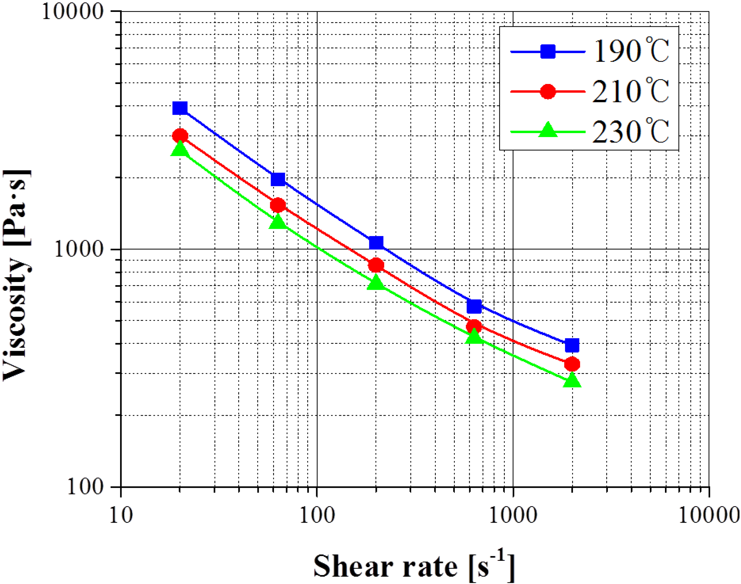
2. Measurements of Viscosity for SUS 316 L Feedstocks
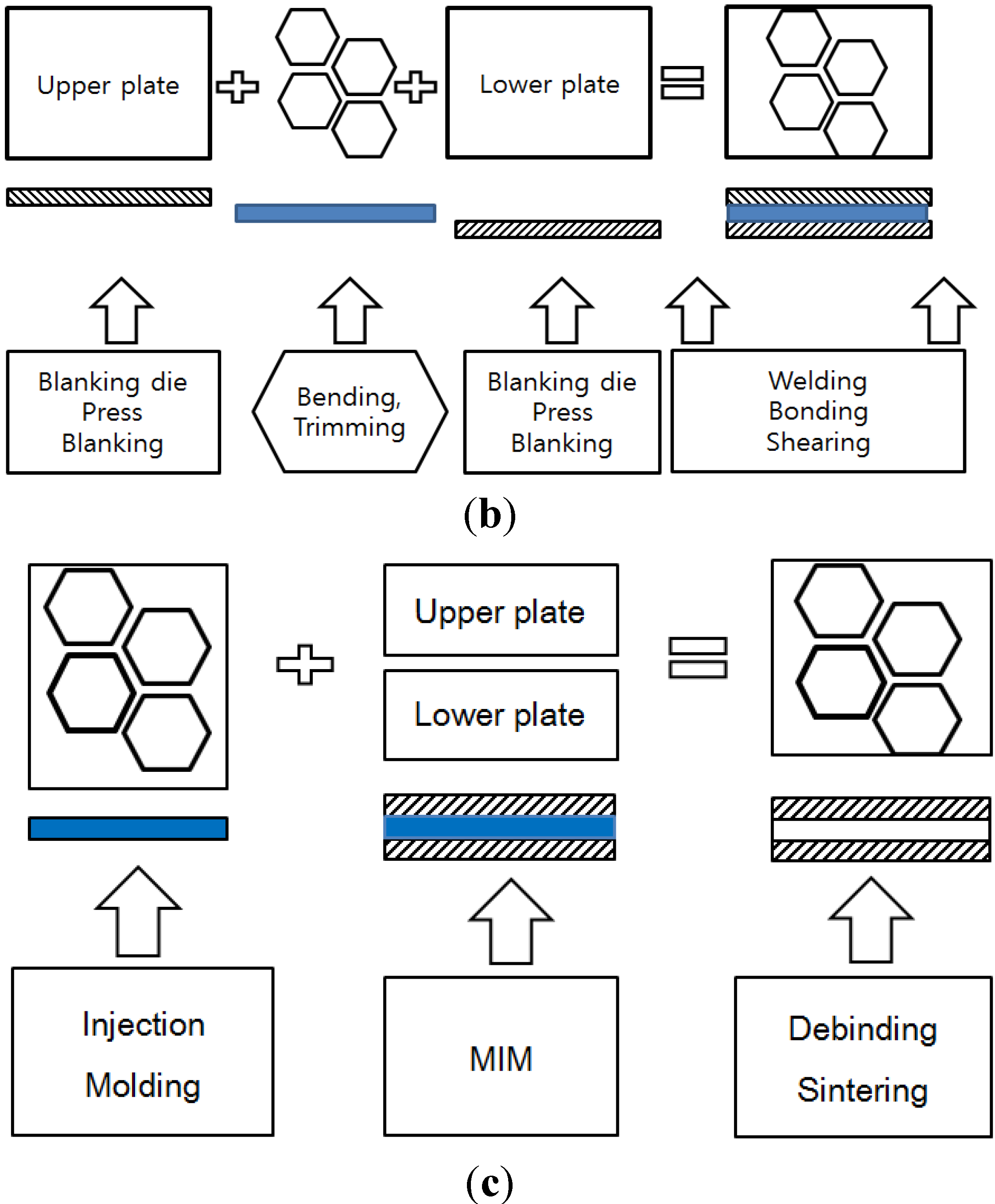
3. Fabrication of Metal Plate with Internal Honeycomb Structure
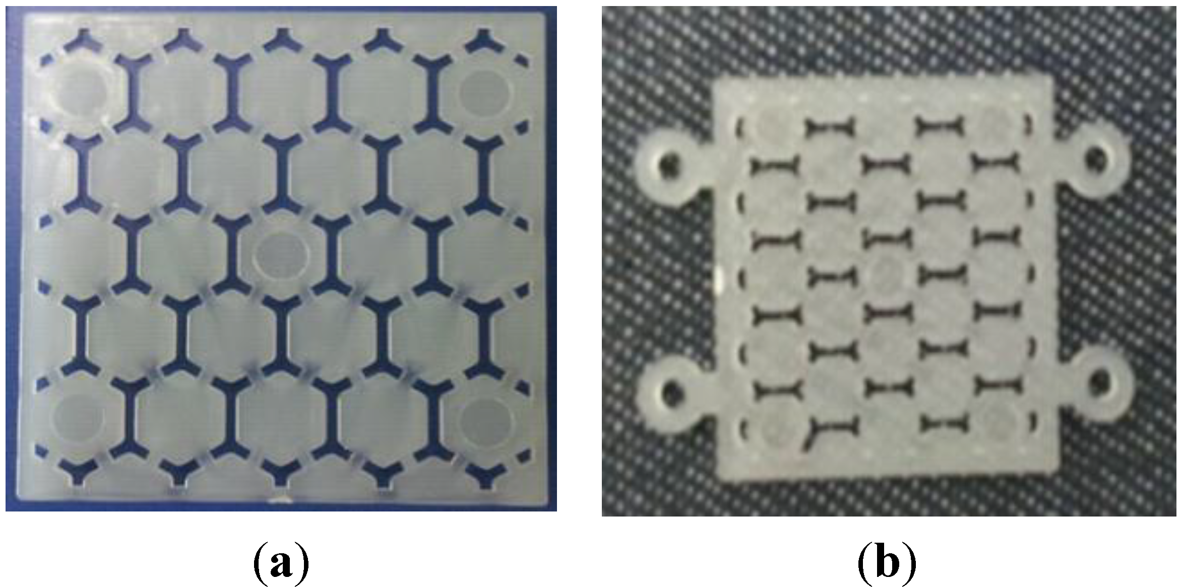
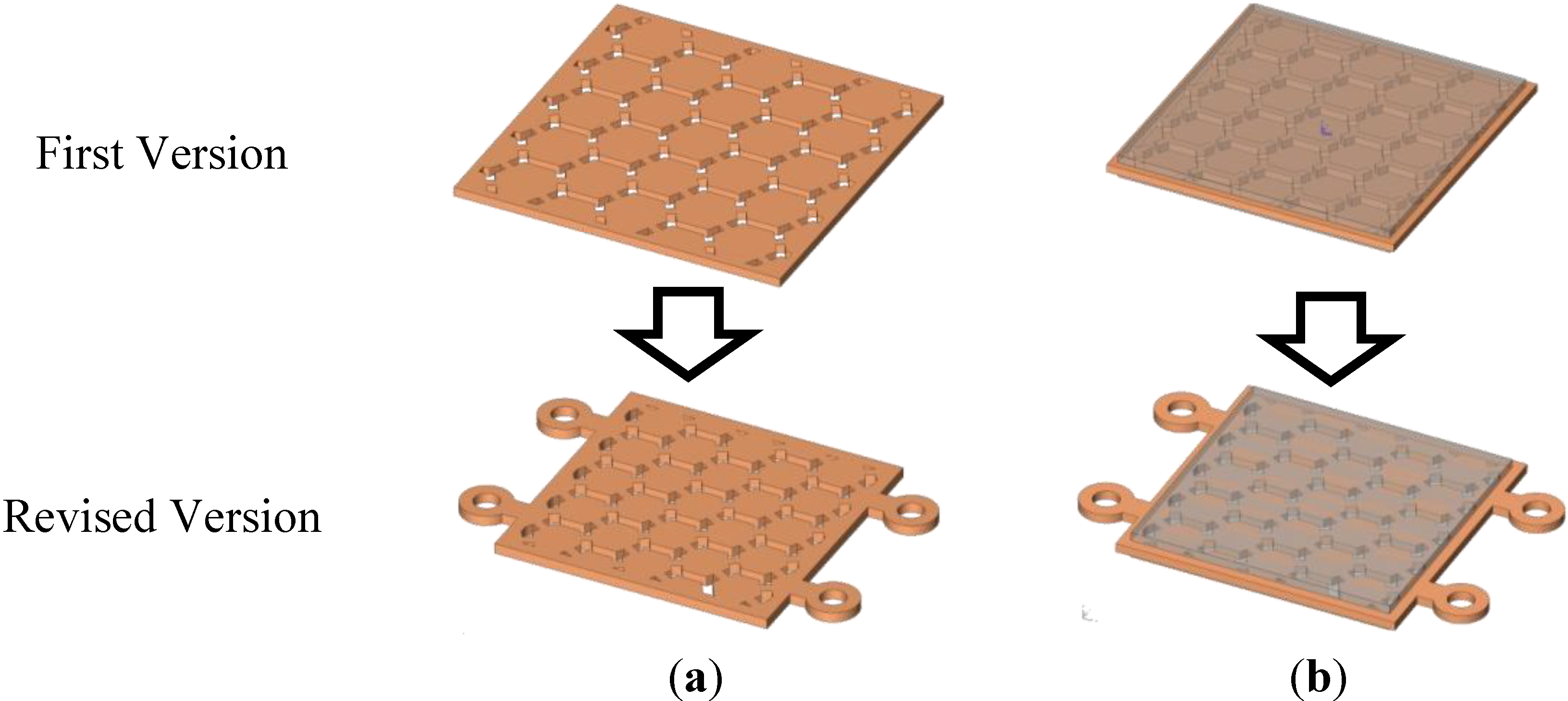
3.1. Design of Sacrificed Polymer Insert with Structure

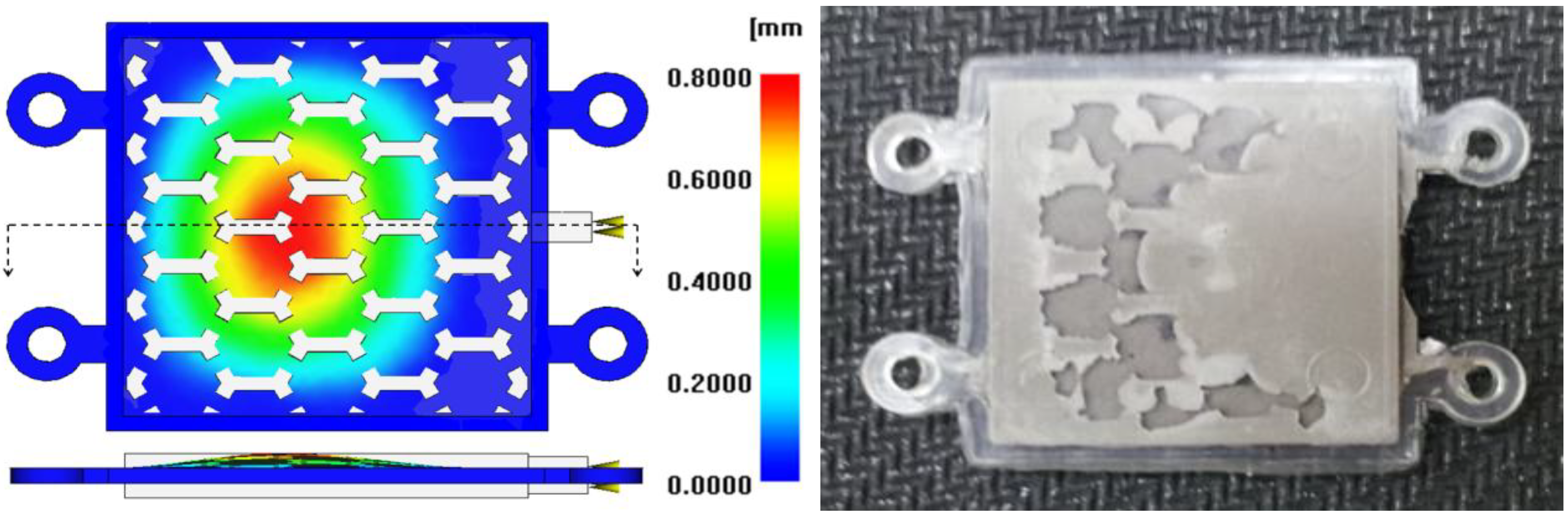
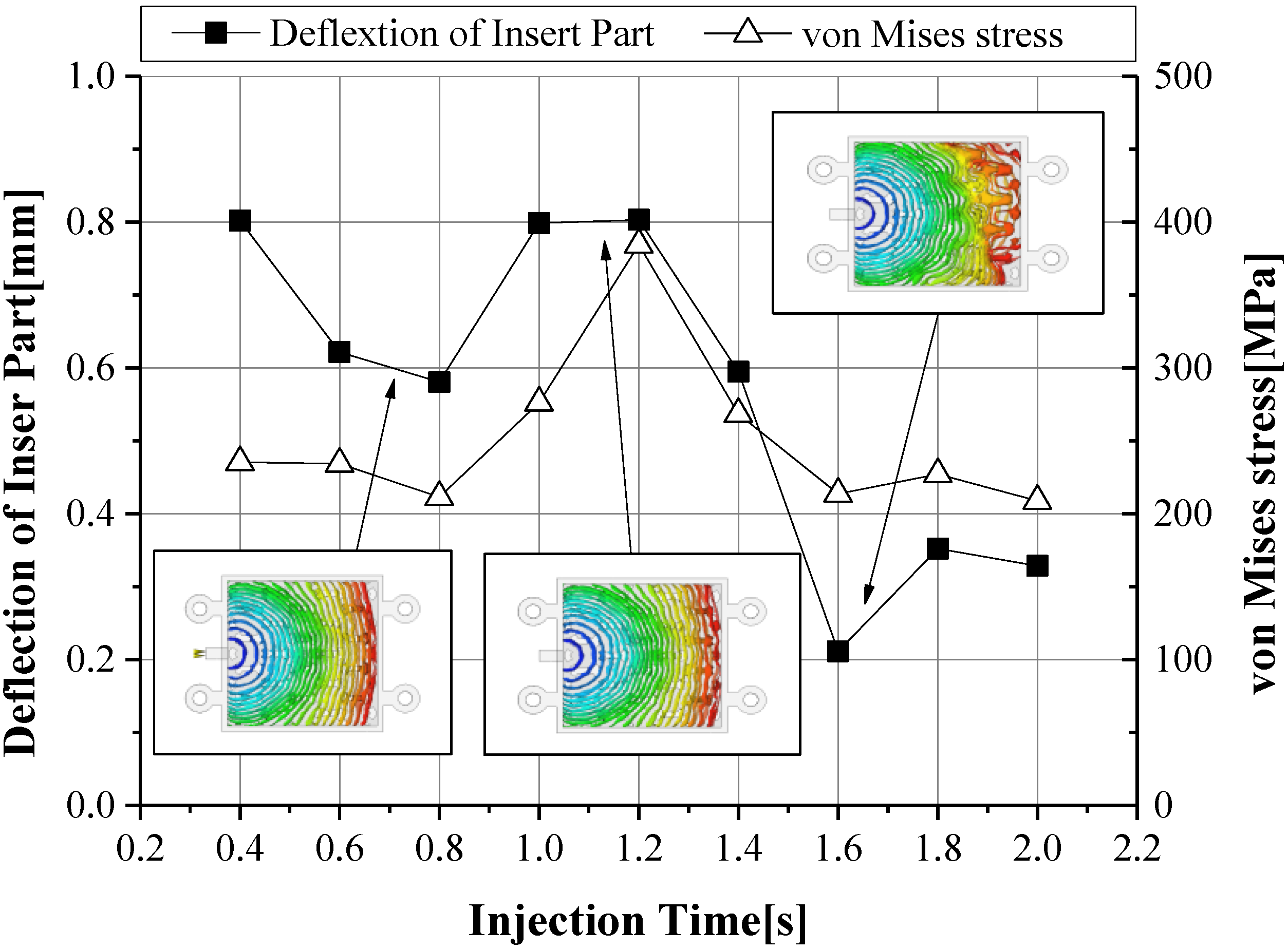
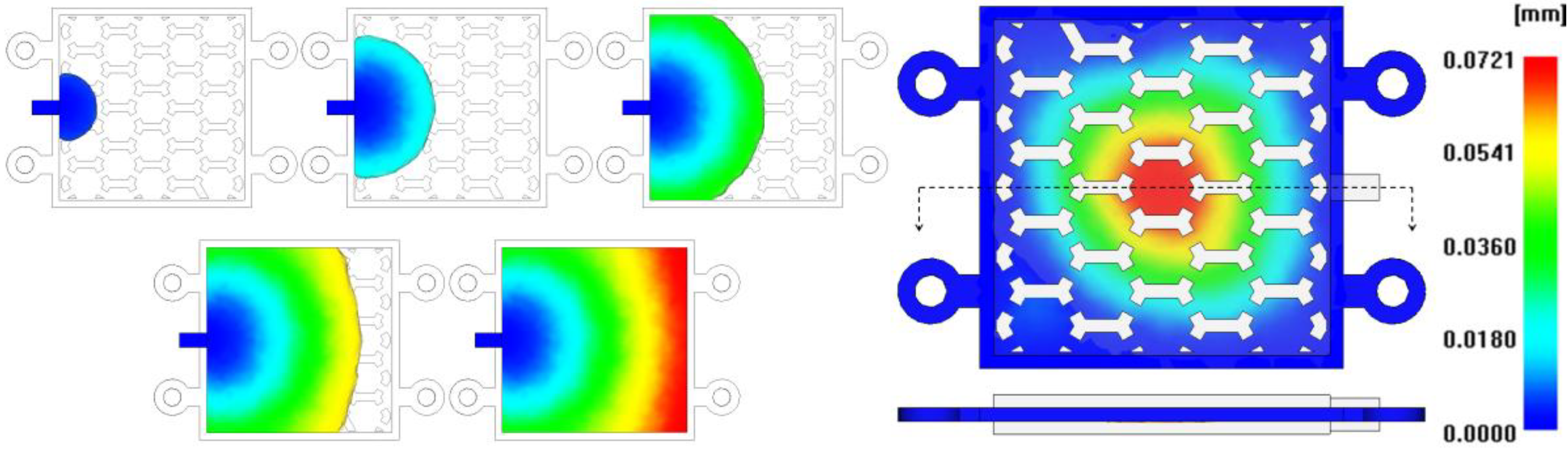
3.2. CAE Simulation for the Checking of Filling during the MIM Process
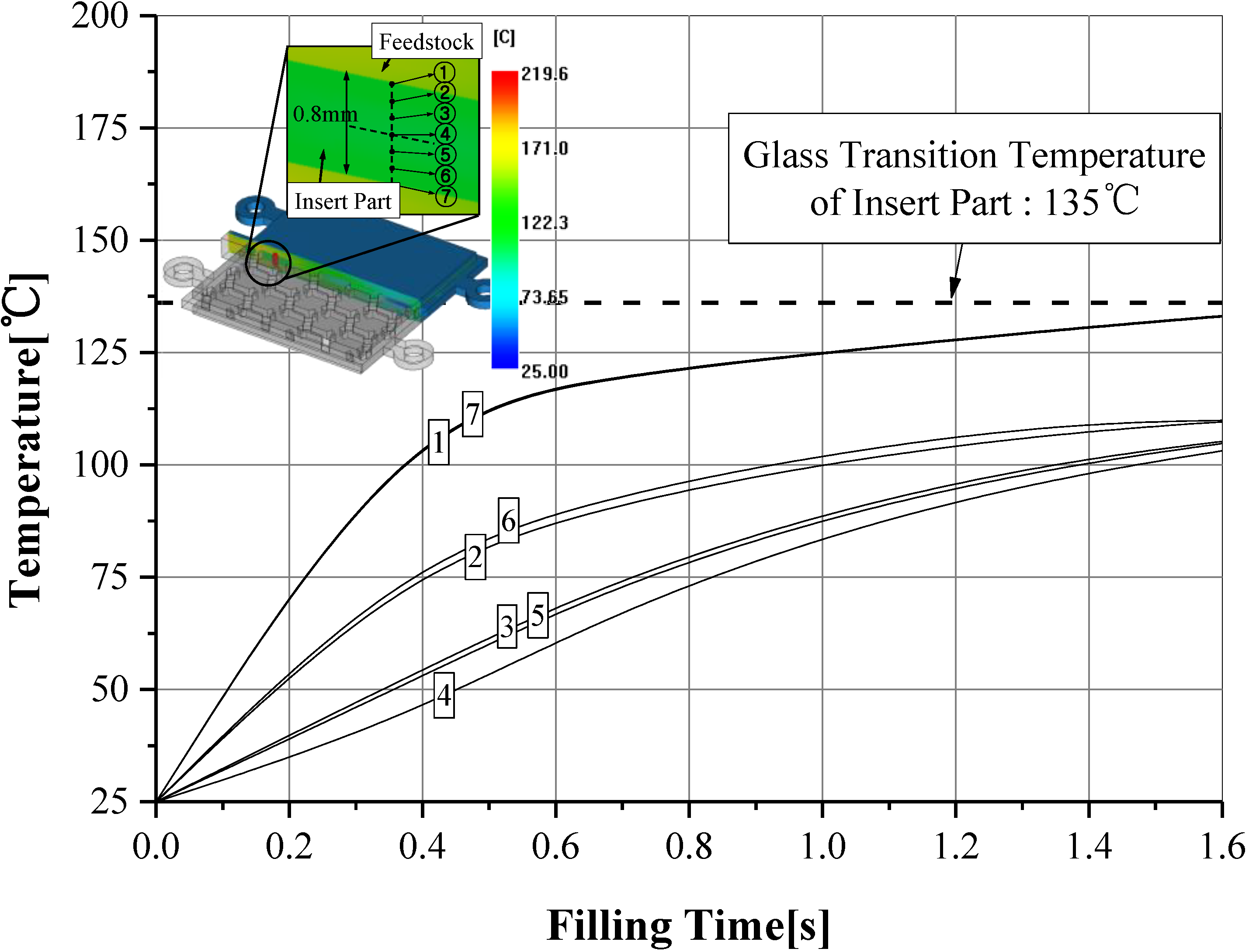
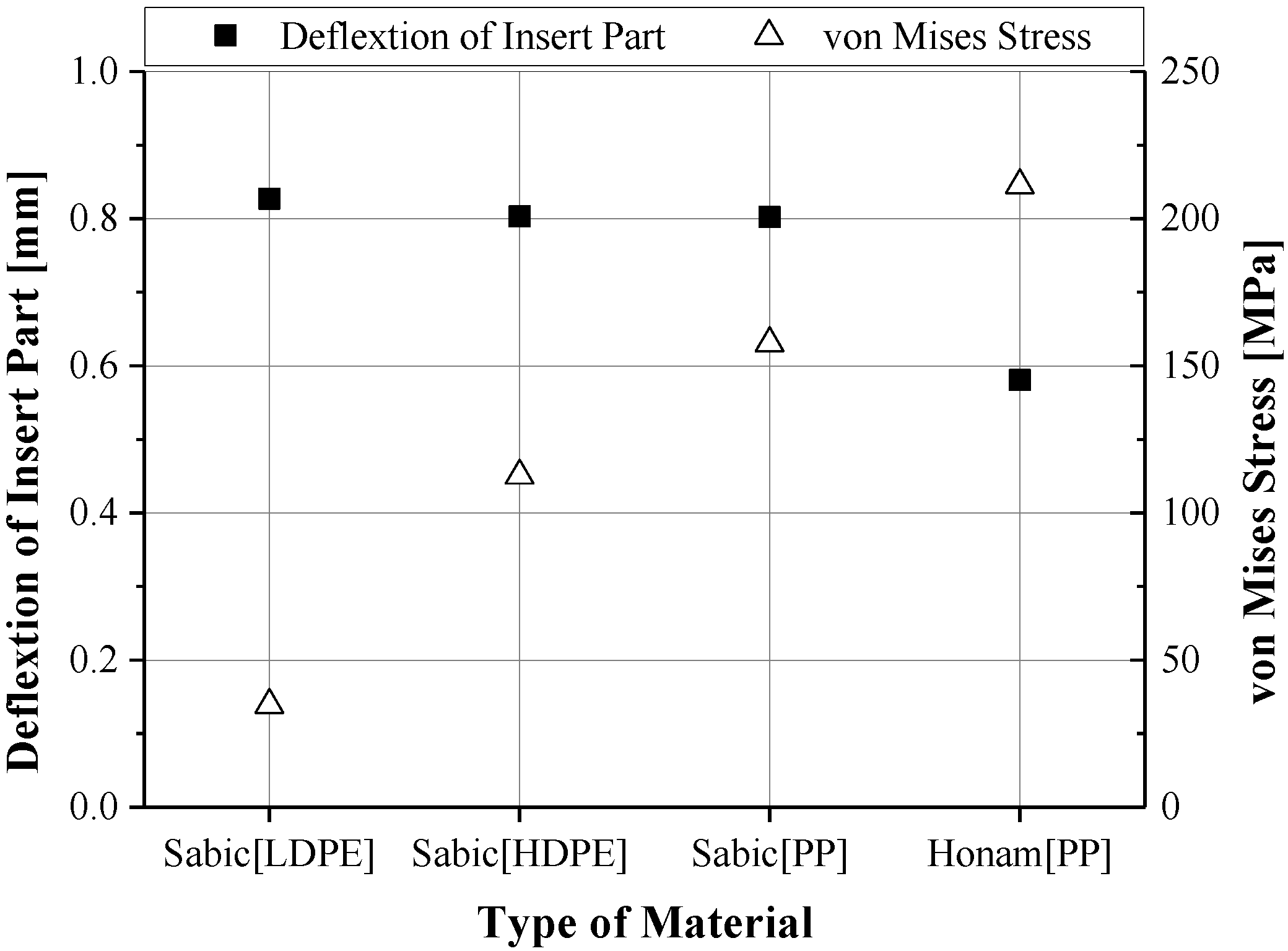
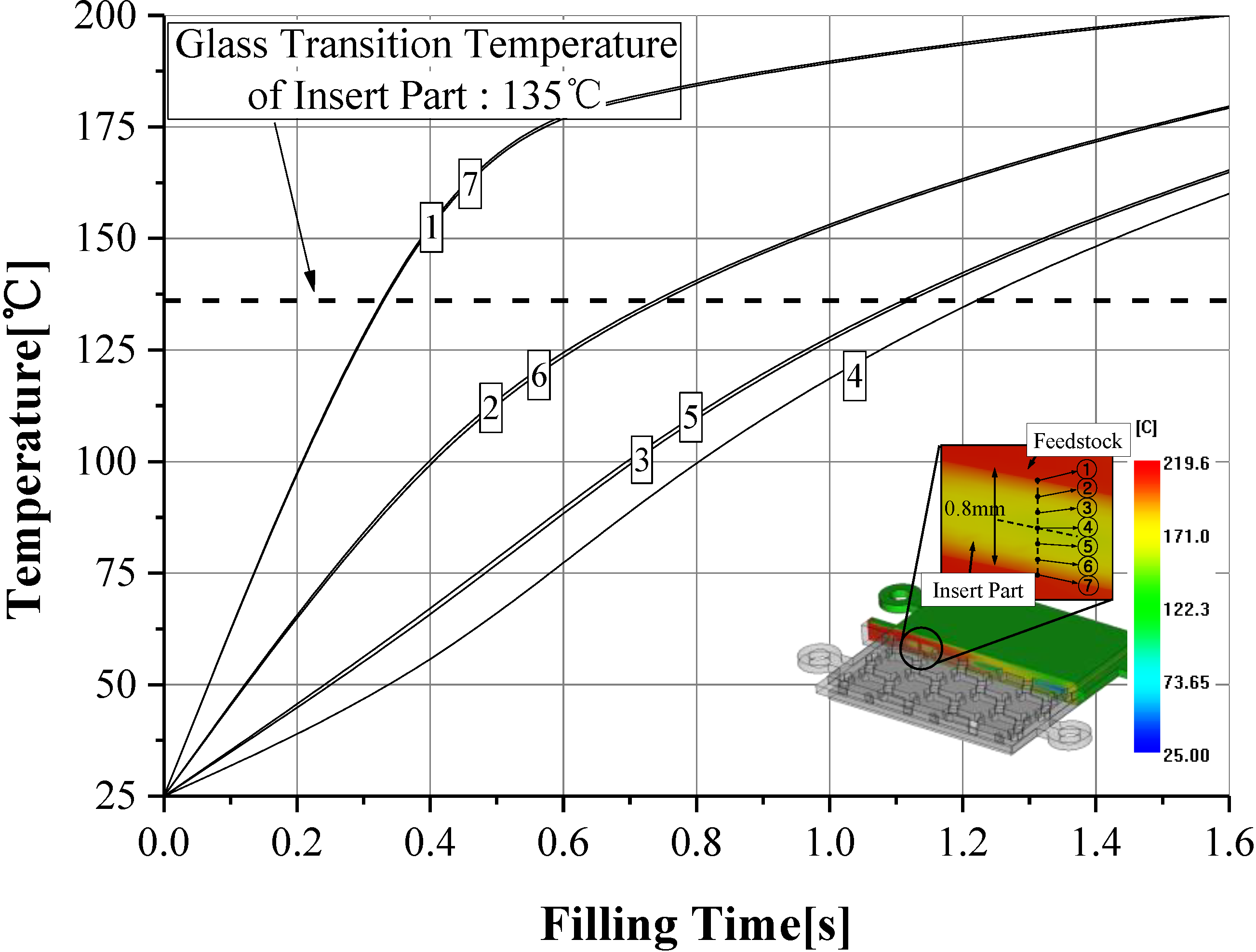
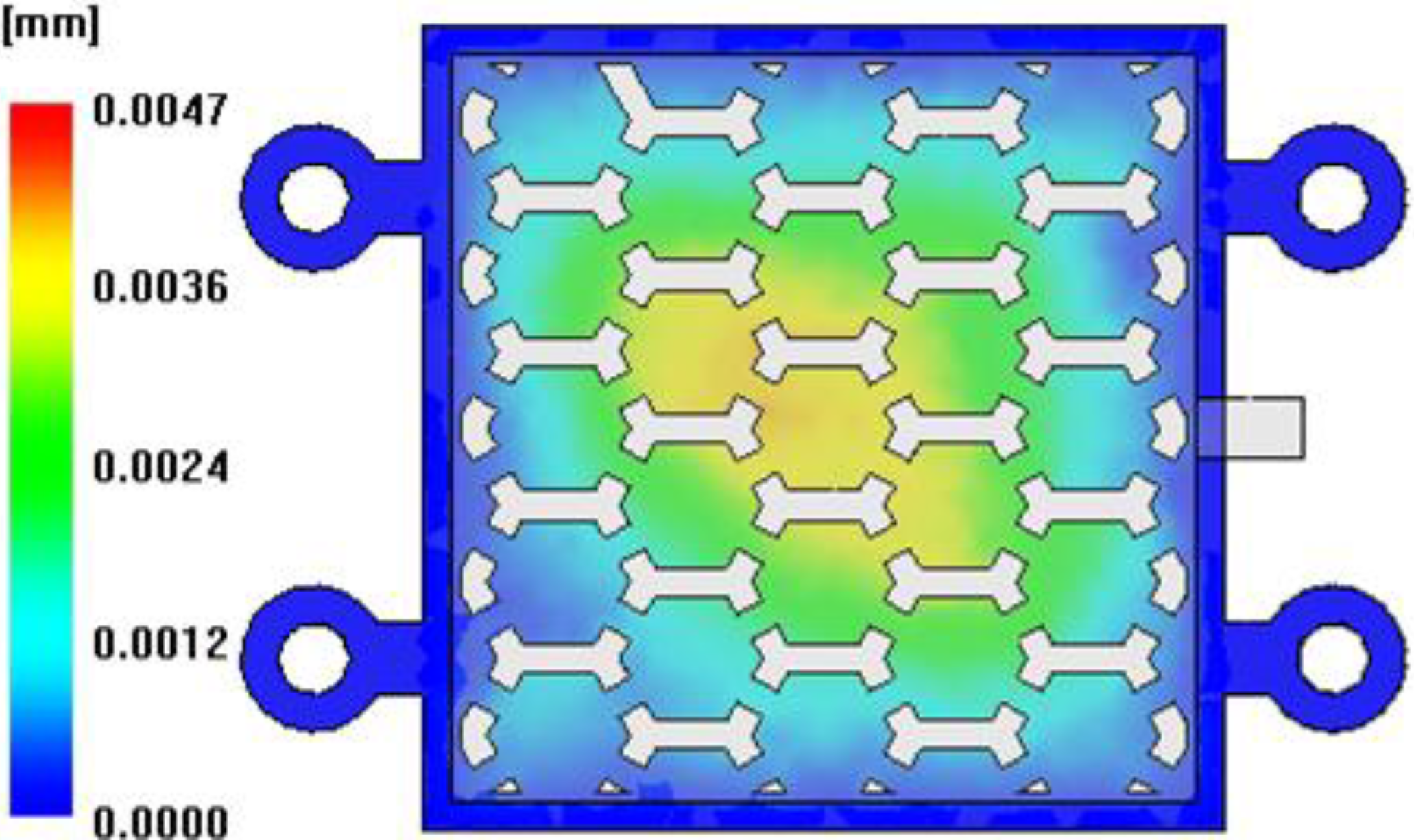
3.2.1. Selection of Material for Sacrificed Polymer Insert and Core Shift Analysis

| Material Type | Unit | PP Honam A-372 | PP Sabic 513MNK10 | HDPE Sabic CCX912 | LDPE Sabic 1965T |
|---|---|---|---|---|---|
| Elastic Modulus | MPa | 3,046 | 1,340 | 911 | 124 |
| Poisson’s Ratio | – | 0.425 | 0.392 | 0.426 | 0.41 |
| Shear Modulus | MPa | 720 | 481.3 | 319.4 | 43.97 |
| Thermal Expansion Coefficient | °C−1 | 6.79 × 10⁵ | 9.05 × 10⁵ | 1.50 × 10⁴ | 1.80 × 10⁴ |
| Glass Transition Temperature | °C | 135 | 123 | 114 | 90 |
| Process parameter | Unit | Value |
|---|---|---|
| Melt Temperature | °C | 170 |
| Mold Temperature | °C | 120 |
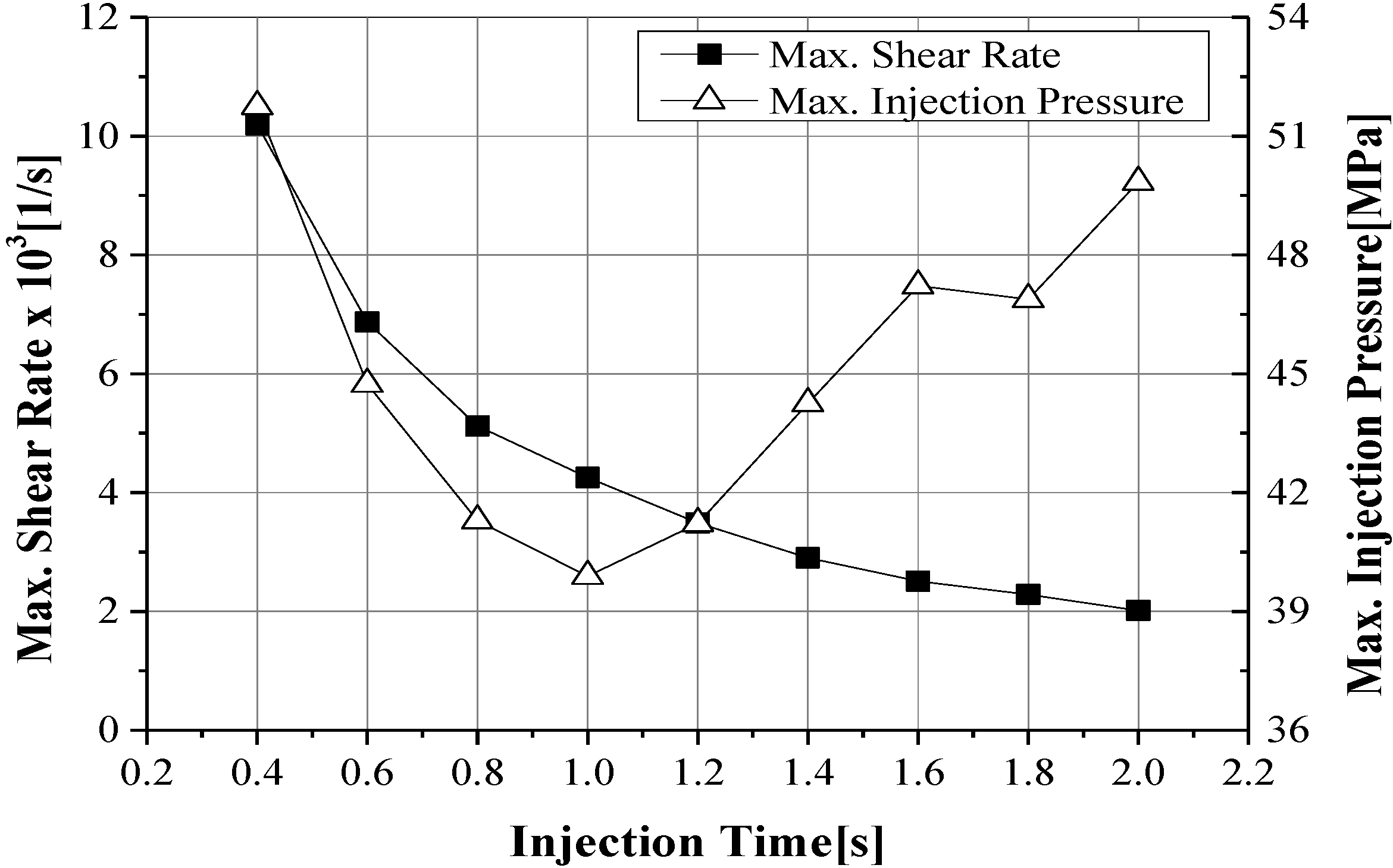
| Injection Time | s | 0.8 |
| Holding Pressure * | % | 80 |
| Holding Time | s | 1.5 |
| Cooling Time | s | 20 |

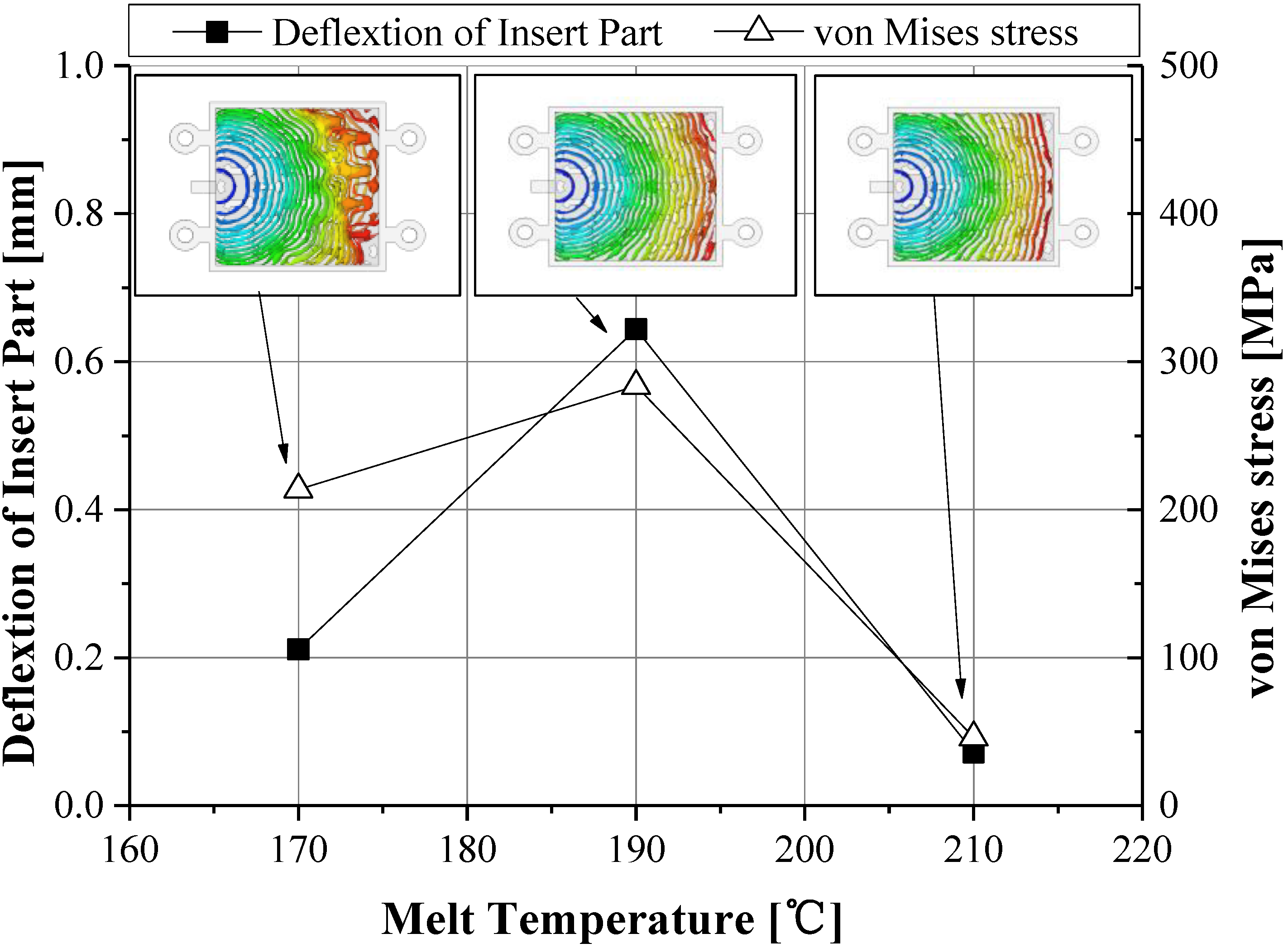
3.2.2. Metal Injection Molding Condition


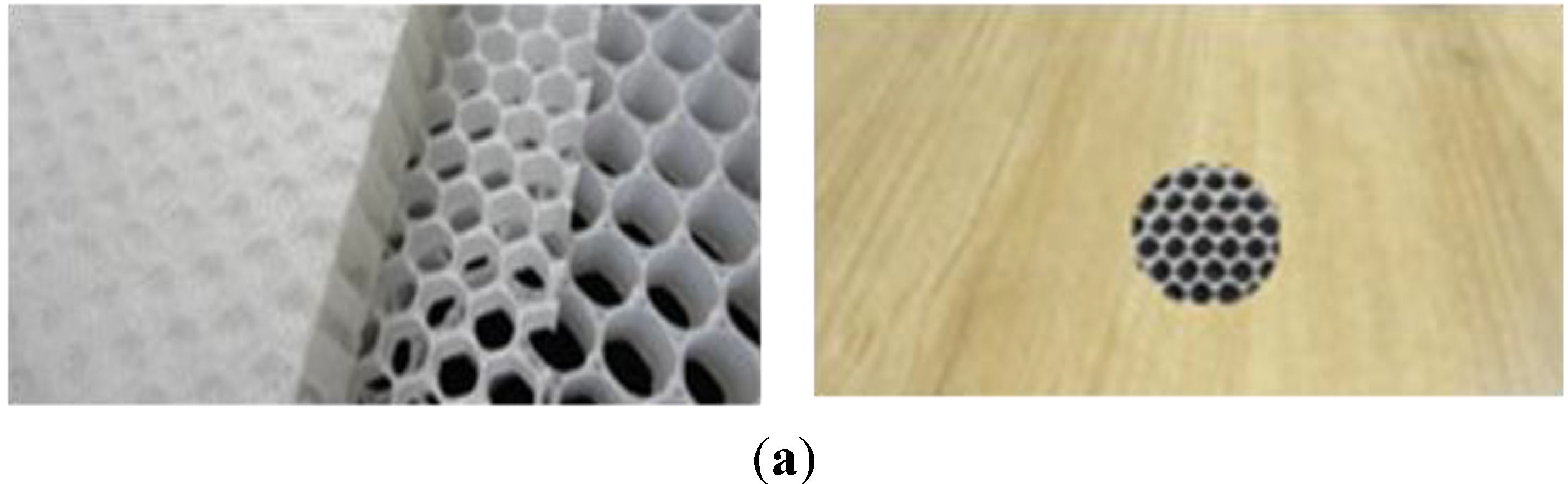
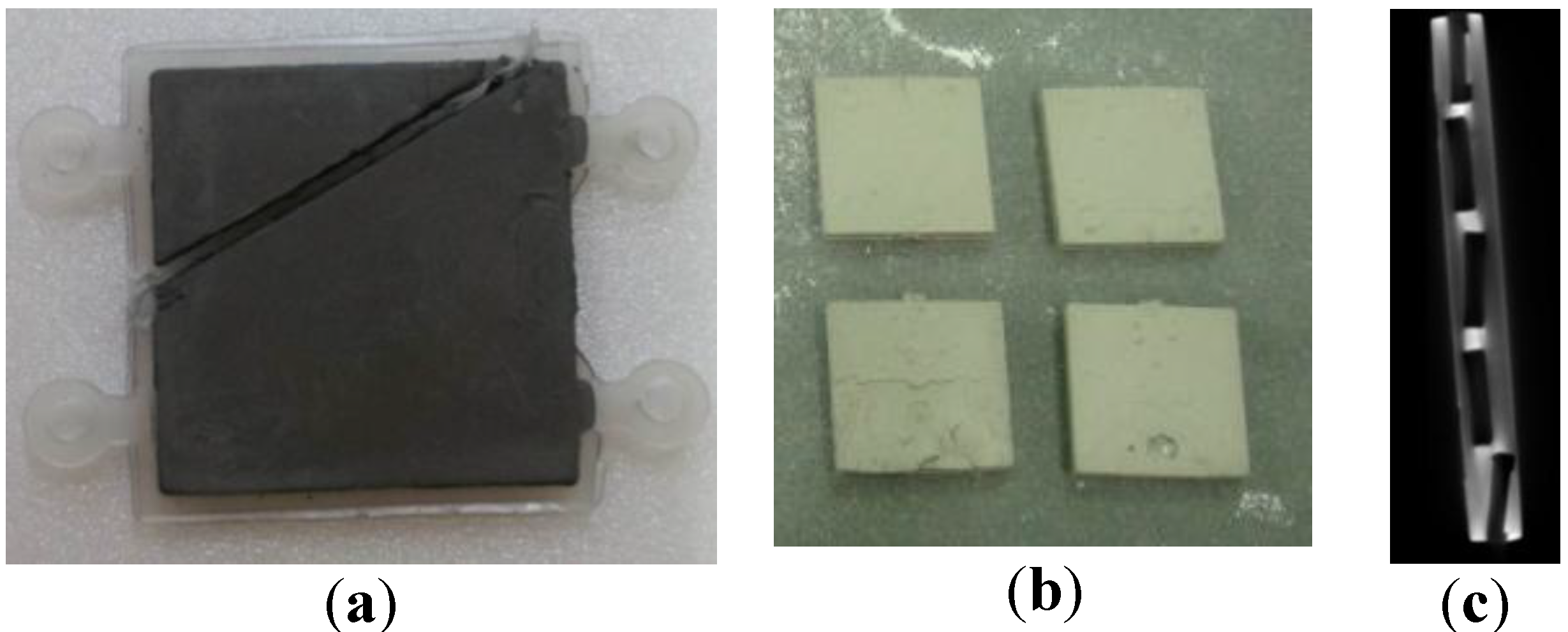
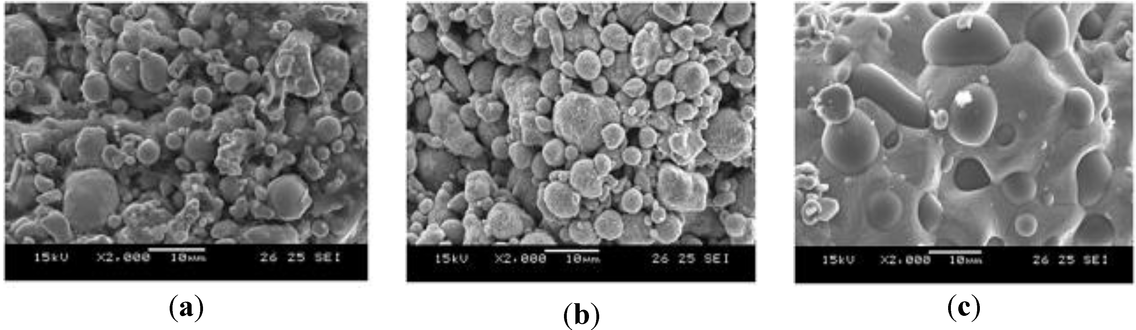
3.3. Metal Injection Molding Process and Post-Processing
4. Conclusions
- (1)
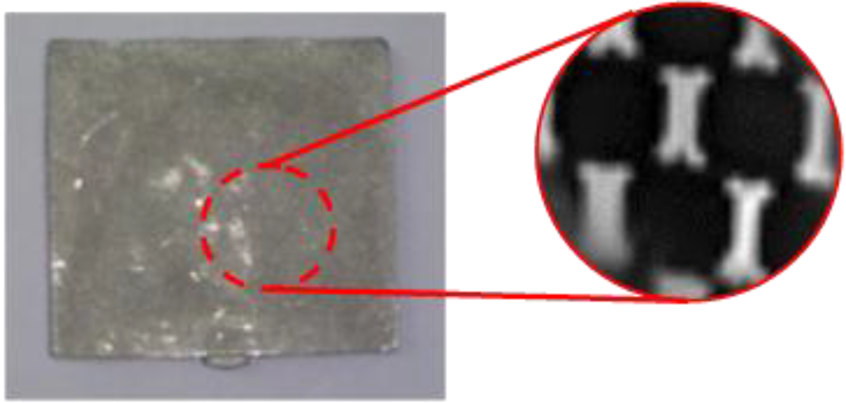
- A stainless steel metal plate with an internal structure was developed using the recommended metal injection molding process.
- (2)
- The sacrificed polymer insert was designed to fix and prevent movement in the MIM mold cavity, and each cell or channel was connected so as to be removed without air trapping during the debinding and sintering processes. These connections would act as channels for fluid applications.
- (3)
- The glass transition temperature of the sacrificed polymer insert would be of high-grade, and this insert should be maintained during the MIM process.
- (4)
- CAE simulations to find a suitable sacrificed polymer insert and an adequate metal injection molding condition were recommended to reduce the development time.
- (5)
- The shrinkage of the target part during post-processing was about 16.3% in thickness and 15.5% in width direction. The total thickness was approximately 2.0 mm.
Acknowledgments
Conflicts of Interest
References
- Sugino, M.; Kobayashi, K.; Nikaido, M.; Kumazawa, T.; Saura, E. Method for Producing Honeycomb-Shaped Metal Moldings. US Patent 4582677, 15 April 1986. [Google Scholar]
- German, R.M. Powder Injection Molding–Design and Applications, 1st ed.; Innovative Material Solutions, Inc.: State College, PA, USA, 2003. [Google Scholar]
- Najmi, L.A.; Lee, D.Y. Modeling of mold filling process for powder injection molding. Polym. Eng. Sci. 1991, 31, 1137–1148. [Google Scholar] [CrossRef]
- Catamold® 316 L A–BASF. Available online: http://www.catamold.de (accessed on 29 October 2013).
- Karatas, C.; Sozen, A.; Arcaklioglu, E.; Erguney, S. Experimental and theoretical investigations of mouldability for feedstocks used in powder injection moulding. Modell. Simul. Eng. 2007, 01. [Google Scholar] [CrossRef]
- Li, Y.; Huang, B.; Qu, X. Viscosity and melt rheology of metal injection moulding feedstocks. Powder Metall. 1999, 42, 86–90. [Google Scholar] [CrossRef]
- Supati, R.; Loh, N.H.; Khor, K.A.; Tor, S.B. Mixing and characterization of feedstock for powder injection molding. Mater. Lett. 2000, 46, 109–114. [Google Scholar] [CrossRef]
- Liu, L.; Loh, N.H.; Tay, B.Y.; Tor, S.B.; Murakoshi, Y.; Maeda, R. Mixing and characterisation of 316 L stainless steel feedstock for micro powder injection molding. Mater. Charact. 2005, 54, 230–238. [Google Scholar] [CrossRef]
- Khakbiz, M.; Simchi, A.; Bagheri, R. Analysis of the rheological behavior and stability of 316 L stainless steel–TiC powder injection molding feedstock. Mater. Sci. Eng. A 2005, 407, 105–113. [Google Scholar] [CrossRef]
- Loh, N.H.; Tor, S.B.; Khor, K.A. Production of metal matrix composite part by powder injection molding. J. Mater. Process. Technol. 2001, 108, 398–407. [Google Scholar] [CrossRef]
- Zauner, R.; Binet, C.; Heaney, D.F.; Piemme, J. Variability of feedstock viscosity and its correlation with dimensional variability of green powder injection moulded components. Powder Metall. 2004, 47, 150–155. [Google Scholar] [CrossRef]
- Jung, W.; Heo, Y.; Yoon, G.; Shin, K.; Chang, S.; Kim, G.; Cho, M. Micro machining of injection mold inserts for fluidic channel of polymeric biochips. Sensors 2007, 7, 1643–1654. [Google Scholar] [CrossRef]
- Ahn, S.Y.; Park, S.J.; Lee, S.; Atre, S.V.; German, R.M. Effect of powders and binders on material properties and molding parameters in iron and stainless steel powder injection molding process. Powder Technol. 2009, 193, 162–169. [Google Scholar] [CrossRef]
- Ling, D.; Gupta, M.; Myers, P.R.; Upadhyay, R.K. Prediction of Core Deflection in Ceramic Injection Molding. In Proceedings of the SPE ANTEC 2005, Boston, MA, USA, 1 May 2005.
- Bakharev, A.; Fan, Z.; Costa, F.; Han, S.J.; Kennedy, P. Prediction of Core Shift Effects Using Mold Filling Simulation. In Proceedings of the SPE ANTEC 2004, Chicago, IL, USA, 16 May 2004.
- Kennedy, P. Flow Analysis of Injection Molds, 2nd ed.; Hanser & Gardner Publications Inc.: New York, NY, USA, 1995. [Google Scholar]
- Barriere, T.H.; Liu, B.; Gelin, J.C. Determination of the optimal process parameters in metal injection molding from experiments and numerical modeling. J. Mater. Process. Technol. 2003, 143–144, 636–644. [Google Scholar] [CrossRef]
- Hausnerova, B.; Sedlacek, T.; Filip, P.; Saha, P. The effect of powder characteristics on pressure sensitivity of powder injection moulding compounds. Powder Technol. 2011, 206, 209–213. [Google Scholar] [CrossRef]
- Ahn, D.G.; Kim, D.W.; Yoon, Y.U. Optimal injection molding conditions considering the core shift for a plastic battery case with thin and deep walls. J. Mech. Sci. Technol. 2010, 24, 145–148. [Google Scholar] [CrossRef]
- Shepard, T.A.; O’Connell, M.; Powell, K.; Charwinsky, S. Minimising coreshift in injection moulded container. J. Plast. Eng. 1996, 52, 27–29. [Google Scholar]
- Yang, J.K.; Xu, Y.J. CAE-based injection molding analysis of mobile phone battery cover. Adv. Mater. Res. 2012, 538–541, 1130–1133. [Google Scholar]
- Chen, J.P.; Ding, Z.P. Analysis of volumetric shrinkage and optimization of process parameters in injection molding. Adv. Mater. Process Technol. 2012, 217–219, 2065–2069. [Google Scholar]
- Xu, L.; Xu, W.; Chen, Y. Plastic injection molding process optimization using software. J. Vehic. Des. 2001, 25, 53–63. [Google Scholar] [CrossRef]
- Ilinca, F.; Hetu, J.F.; Derdoufu, A. Metal injection molding: 3D modeling of nonisothermal filling. Polym. Eng. Sci. 2002, 42, 760–770. [Google Scholar] [CrossRef]
- Sung, H.J.; Ha, T.K.; Ahn, S.; Chang, Y.W. Powder injection molding of a 17–4 PH stainless steel and the effect of sintering temperature on its microstructure and mechanical properties. J. Mater. Process. Technol. 2002, 130–131, 321–327. [Google Scholar] [CrossRef]
- Heaney, D.F.; Spina, R. Shrinkage prediction of MIM parts by finite element simulation. J. Comput. Mater. Surf. Eng. 2001, 1, 57–72. [Google Scholar]
© 2013 by the authors. Licensee MDPI, Basel, Switzerland. This article is an open access article distributed under the terms and conditions of the Creative Commons Attribution license ( http://creativecommons.org/licenses/by/3.0/).
Share and Cite
Shin, K.; Heo, Y.; Park, H.; Chang, S.; Rhee, B. Development of Metal Plate with Internal Structure Utilizing the Metal Injection Molding (MIM) Process. Materials 2013, 6, 5878-5892. https://doi.org/10.3390/ma6125878
Shin K, Heo Y, Park H, Chang S, Rhee B. Development of Metal Plate with Internal Structure Utilizing the Metal Injection Molding (MIM) Process. Materials. 2013; 6(12):5878-5892. https://doi.org/10.3390/ma6125878
Chicago/Turabian StyleShin, Kwangho, Youngmoo Heo, Hyungpil Park, Sungho Chang, and Byungohk Rhee. 2013. "Development of Metal Plate with Internal Structure Utilizing the Metal Injection Molding (MIM) Process" Materials 6, no. 12: 5878-5892. https://doi.org/10.3390/ma6125878