Article

Durability Characteristics Analysis of Plastic Worm Wheel with Glass Fiber Reinforced Polyamide

1
Molds & Dies Technology R&D Group, Korea Institute of Industrial Technology, 7-47, Songdo-dong, Yeonsu-gu, Incheon 406-840, Korea
2
Division of Mechanical System Engineering, University of Incheon, 12-1, Songdo-dong, Yeonsu-gu, Incheon 406-772, Korea
*
Author to whom correspondence should be addressed.
Materials 2013, 6(5), 1873-1890; https://doi.org/10.3390/ma6051873
Submission received: 28 February 2013 / Revised: 6 April 2013 / Accepted: 27 April 2013 / Published: 10 May 2013

Abstract

:
Plastic worm wheel is widely used in the vehicle manufacturing field because it is favorable for weight lightening, vibration and noise reduction, as well as corrosion resistance. However, it is very difficult for general plastics to secure the mechanical properties that are required for vehicle gears. If the plastic resin is reinforced by glass fiber in the fabrication process of plastic worm wheel, it is possible to achieve the mechanical properties of metallic material levels. In this study, the mechanical characteristic analysis of the glass-reinforced plastic worm wheel, according to the contents of glass fiber, is performed by analytic and experimental methods. In the case of the glass fiber-reinforced resin, the orientation and contents of glass fibers can influence the mechanical properties. For the characteristic prediction of plastic worm wheel, computer-aided engineering (CAE) analysis processes such as structural and injection molding analysis were executed with the polyamide resin reinforcement glass fiber (25 wt %, 50 wt %). The injection mold for fabricating the prototype plastic worm wheel was designed and made to reflect the CAE analysis results. Finally, the durability of prototype plastic worm wheel fabricated by the injection molding process was evaluated by the experimental method and the characteristics according to the glass fiber contents.

1. Introduction

MDPS (motor-driven power steering), a drive-steering system device that functions by means of a motor, is superior to the existing HPS (hydraulic power steering) in that it reduces the driver’s workload for operating the steering wheel. Thus, the percentage of automobiles with MDPS has been drastically increasing recently [1]. Unlike HPS, which assists steering by using the oil pressure generated by existing hydraulic motors, MDPS assists steering wheel operation with electric motor driving, which realizes the optimal steering power for each running speed range through the precise electric control of the motors and secures excellent stability of high-speed running through reaction and feedback to external forces.
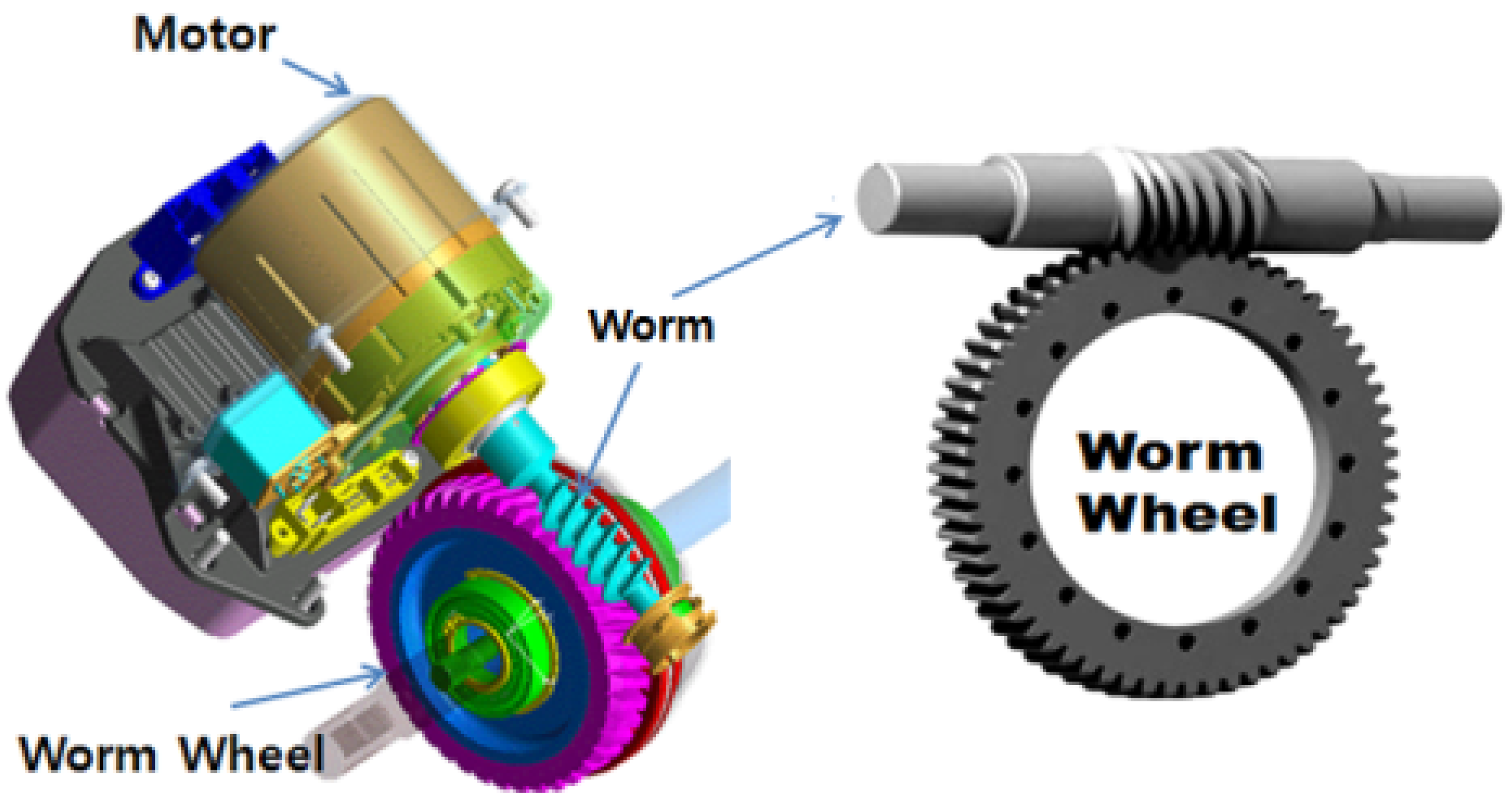
Basically, MDPS consists of an ECU (engine control unit) that assists the steering control unit, the torque sensor, and the reduction gear module that generates compensation torque. The reduction gear module (Figure 1) consists of a motor, a worm and worm wheel set, a backlash compensation apparatus, and so forth. The required specifications are the accuracy, durability, and hardness of the power transmission, as it is the core module part in direct relation to steering rotation. In particular, the worm and worm wheel parts that deliver power from the reduction gear module must secure the appropriate hardness, durability, and weight lightening, as well as noise and vibration reduction. Existing gear parts are mostly made of metals to secure hardness, which results in disadvantages such as high production cost due to the low productivity, poor corrosion resistance, vibration and noise generated, and so forth. Therefore, as the technology for plastic materials and injection molding has developed recently, interest has been aroused for the production of gear parts made of functional plastic materials [2,3,4,5,6]. Plastic gears can be suitable for mass production in terms of production and manufacturing, can be molded with other parts as one body, and have outstanding functional features in terms of vibration reduction, light weight, and corrosion resistance. Due to vehicle weight, however, this type of system has some disadvantage, as well, regarding hardness and durability against load for steering operation, and thus a lot of attention must be paid to securing hardness and durability in designing and manufacturing gears. For the supplement of plastic gear disadvantages, various researches have been performed. Specifically, Hoskins et al. [7] investigated how the generated sound frequency spectrum is influenced by the various polymeric gear materials and operating conditions. In this research, results also demonstrated the influence of increases of surface roughness, wear, and temperature on the respective sound power levels. Senthilvelan et al. [8] carried out the analysis on unreinforced Nylon 6/6, 20% short glass and 20% carbon fiber-reinforced Nylon 6/6 gear materials that indicates the reduction of the damping factor due to the incorporation of fibers. In the results of this study, it is indicated that the reinforced gears generate more gear mesh noise than unreinforced gears. In addition to another study by Senthilvelan [9], unreinforced and 20% short glass fiber-reinforced Nylon 6/6 spur gears were injection molded in the laboratory, and computer-aided simulations of gear manufacturing was carried out. Mao et al. [10] researched an extensive investigation of acetal and nylon gear friction and wear behavior. In this study, tests were performed using the acetal pinion with acetal gears, and nylon pinions with nylon gears, with further investigation carried out using dissimilar polymer gears. In the test results, it was found that the surface temperature was the dominant factor influencing the wear rate, and the initial relationship between the gear surface temperature was the dominant factor influencing the wear rate and an initial relationship between gear surface temperature and gear load capacity has been established and further developed.
Figure 1. Worm and worm wheel system in vehicle steering reduction module of speed.
Materials 06 01873 g001
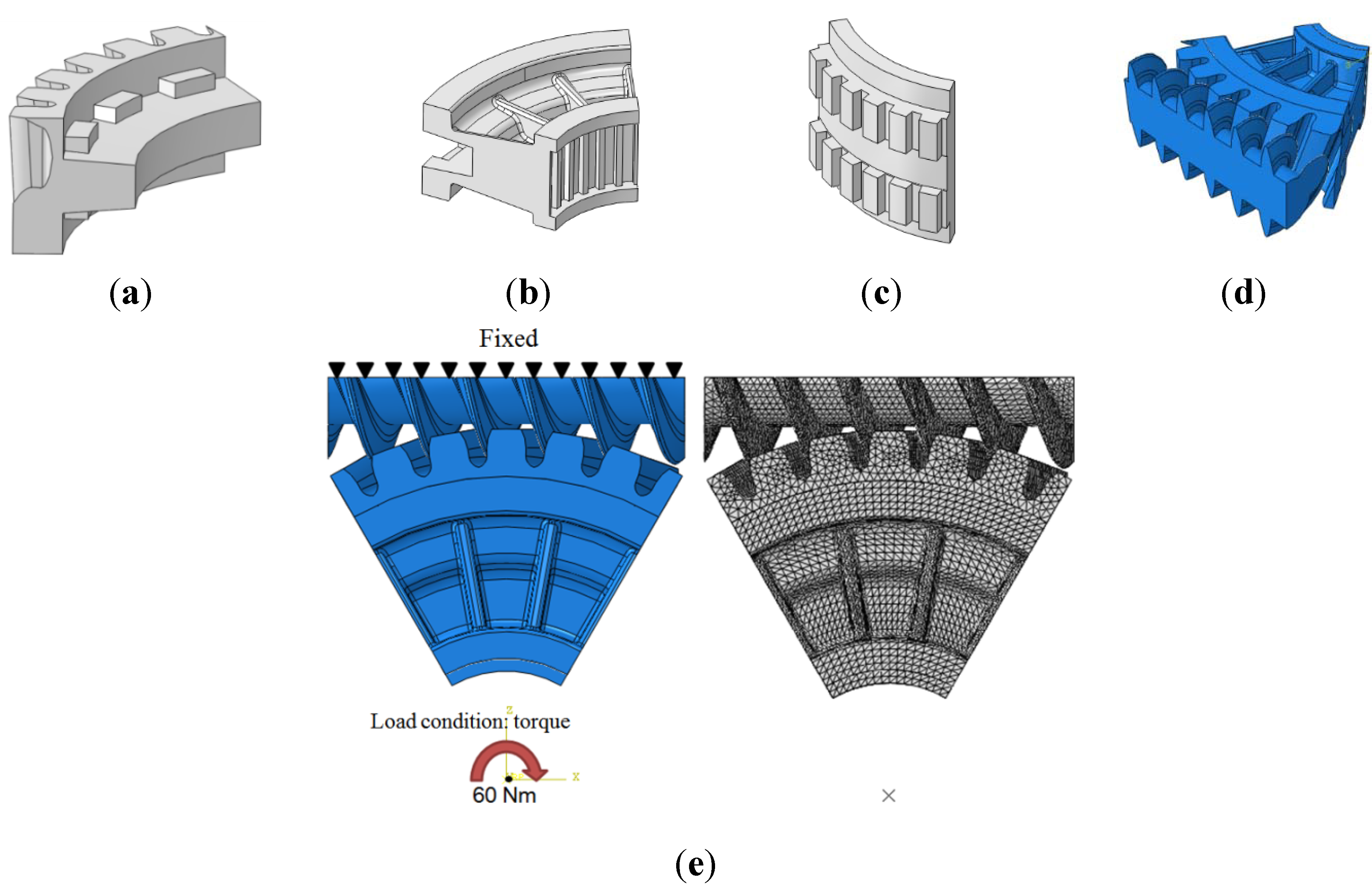
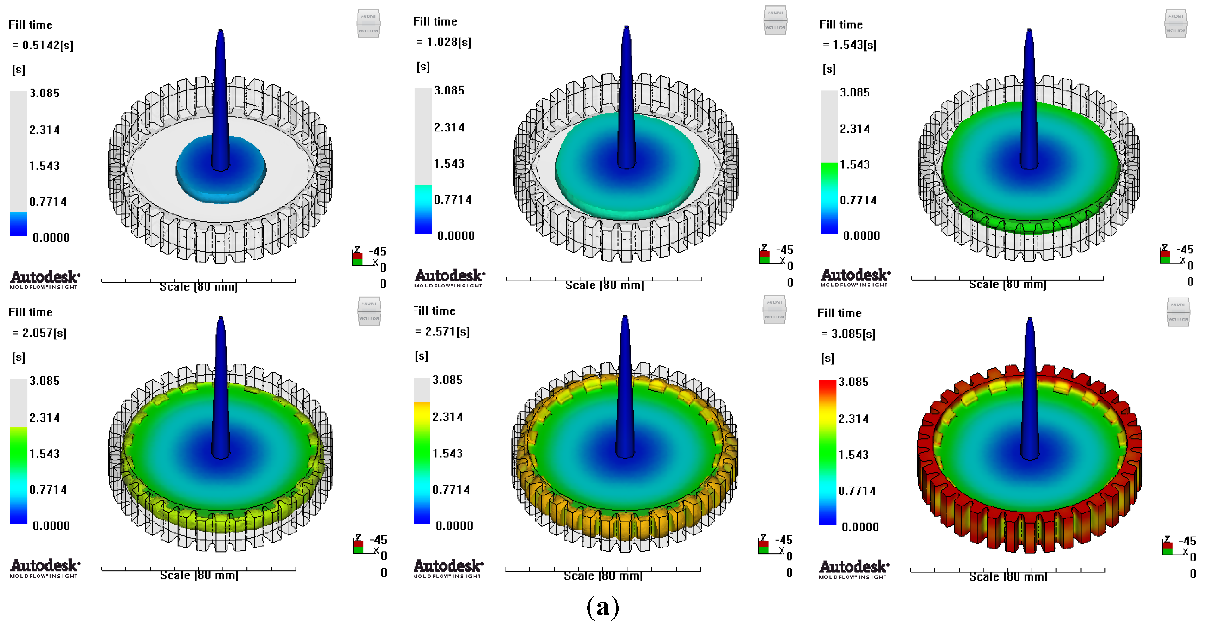
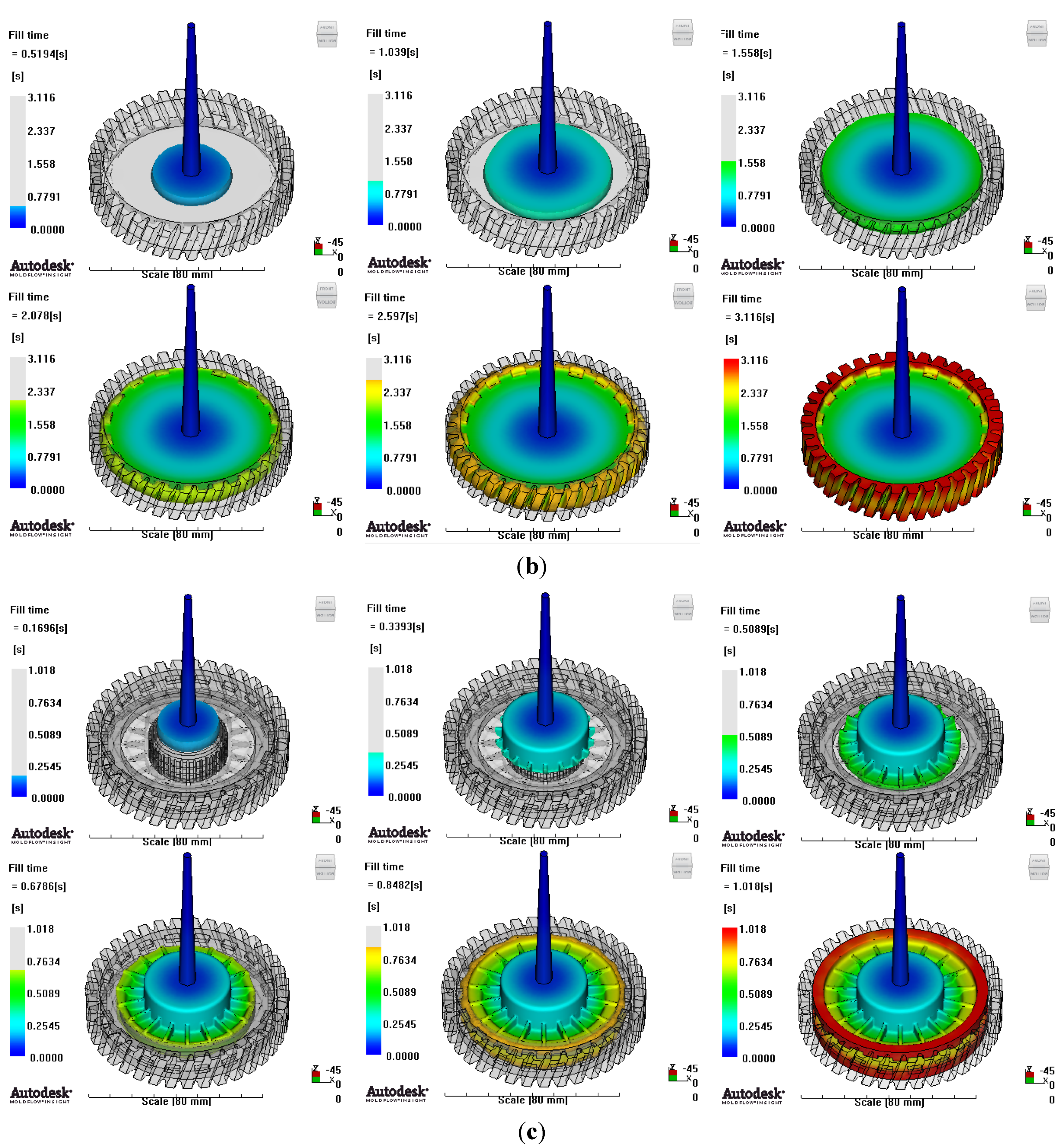
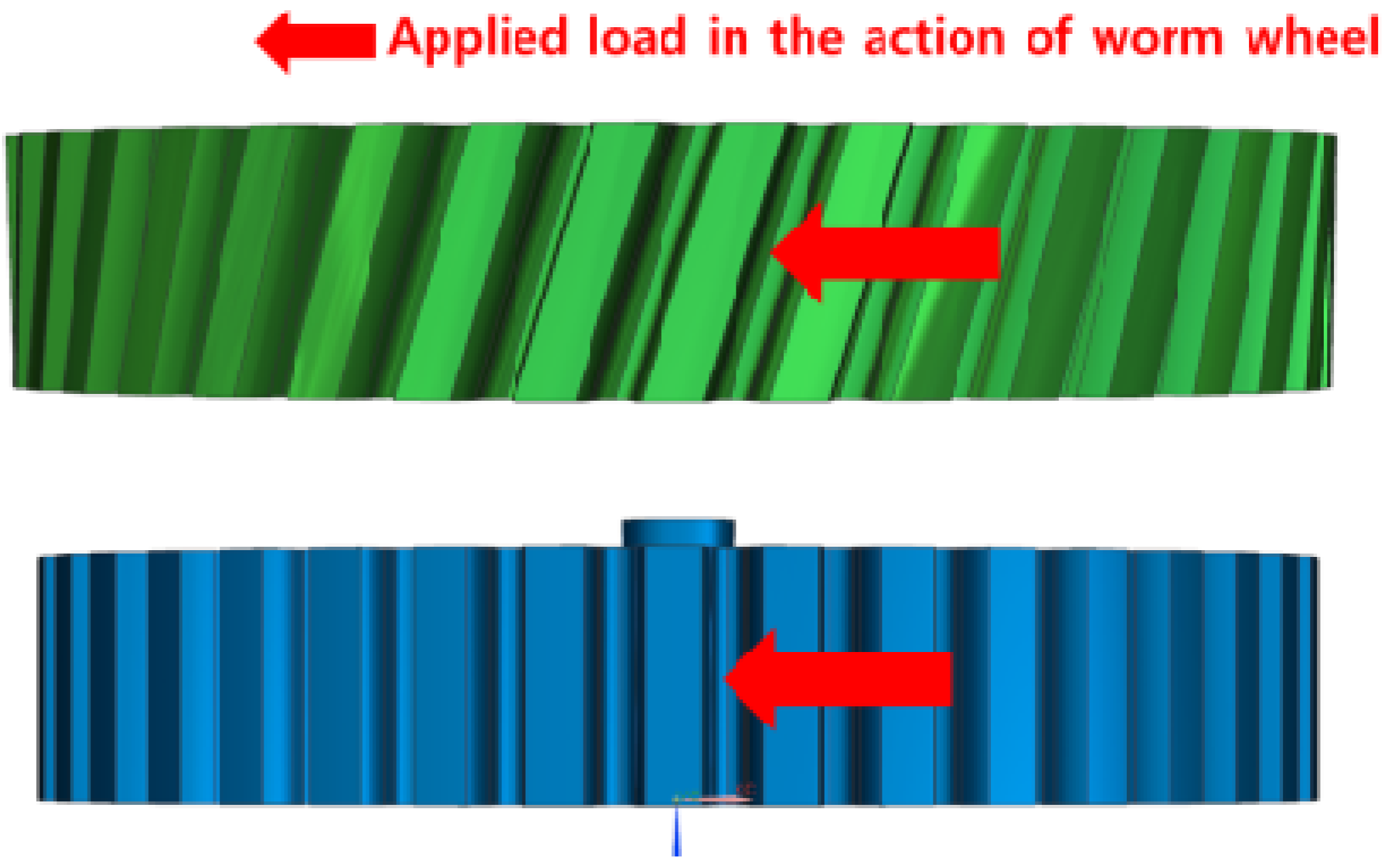
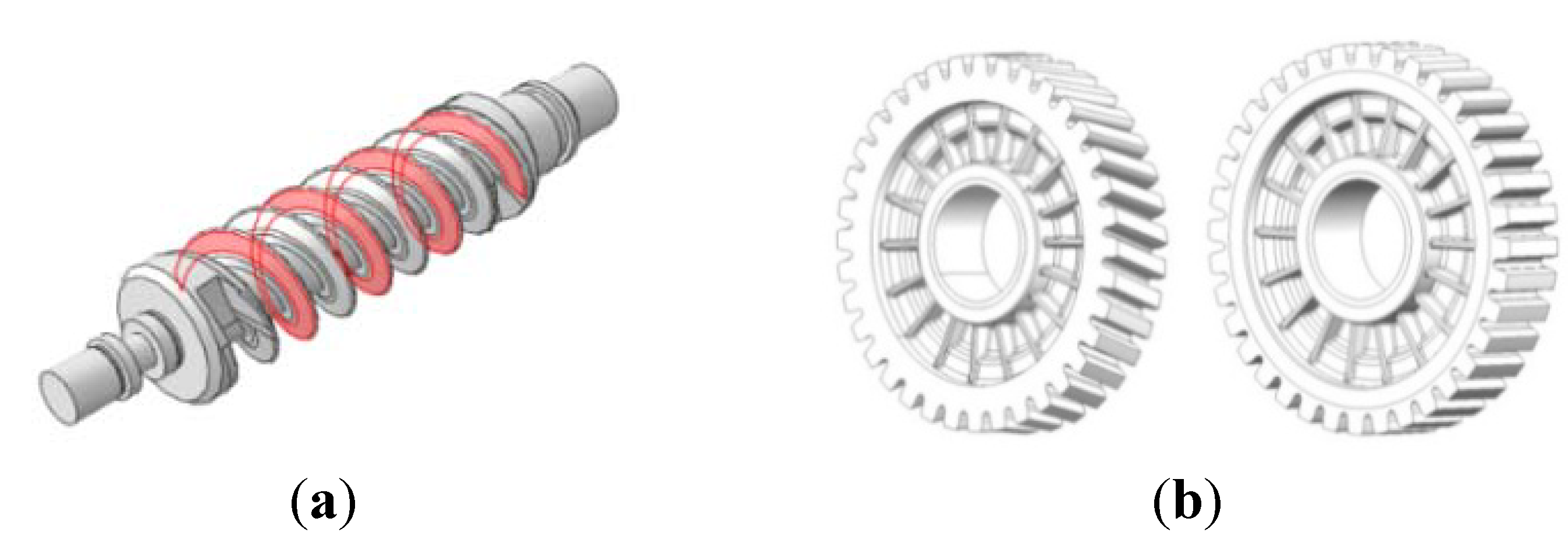
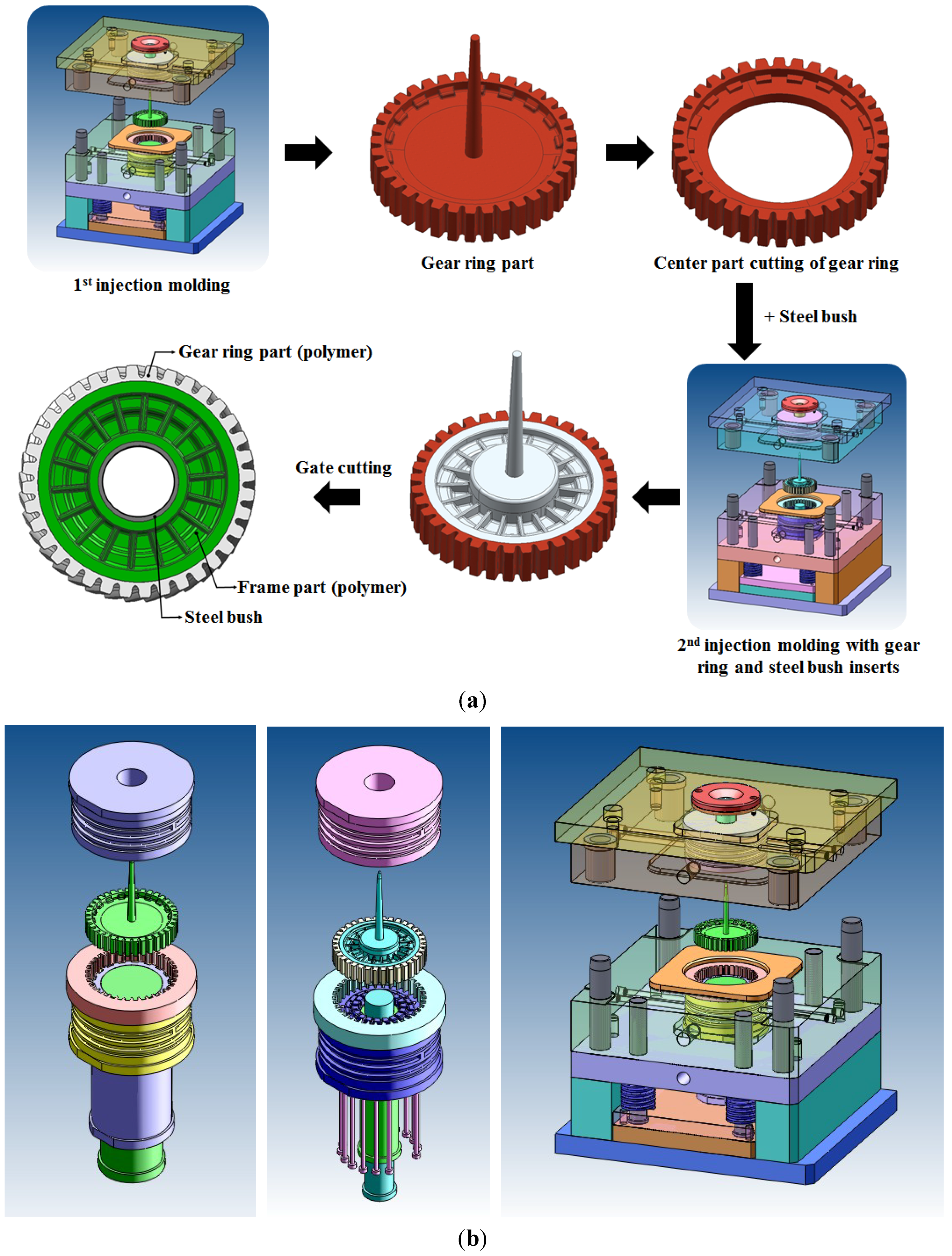
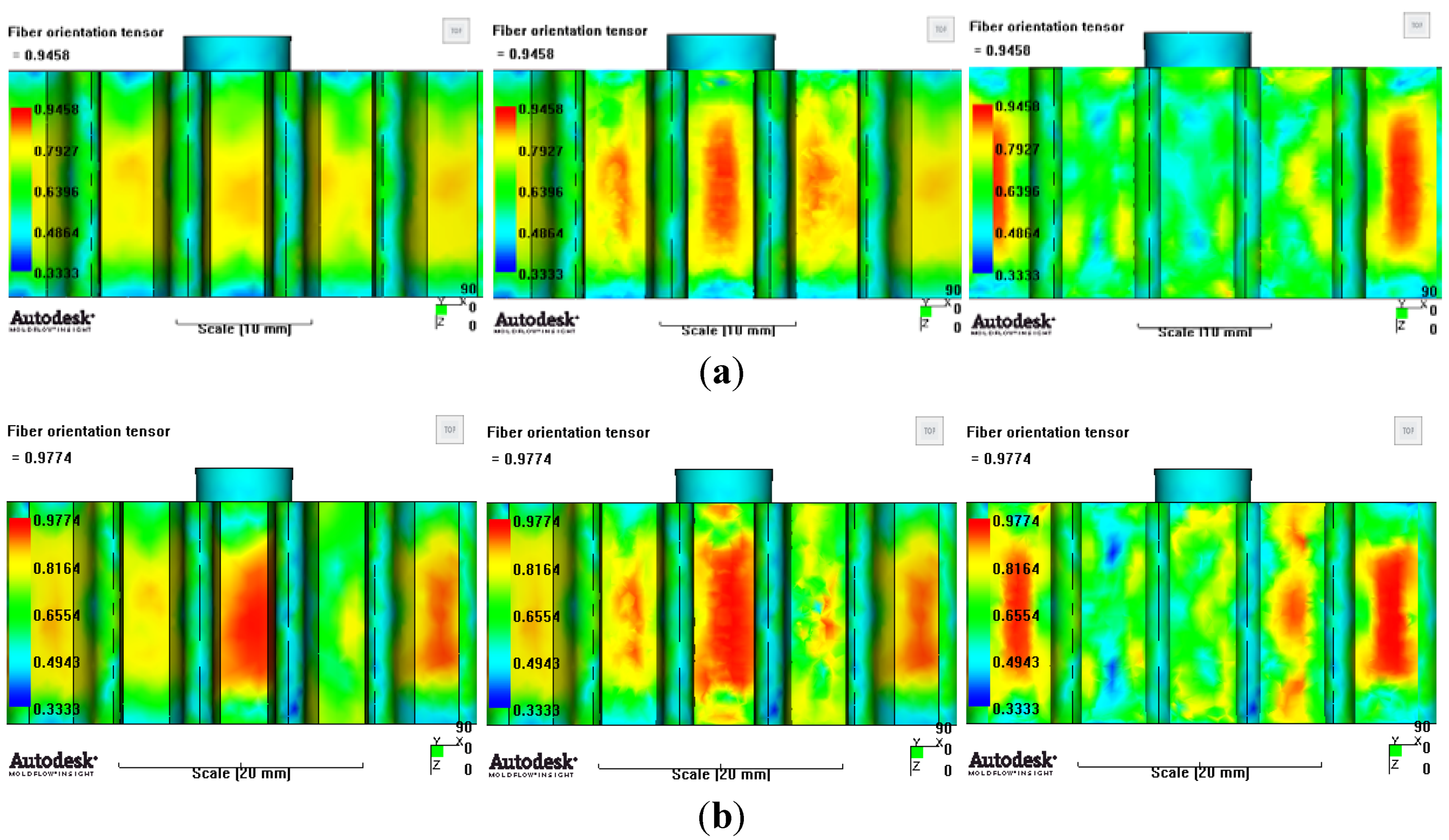
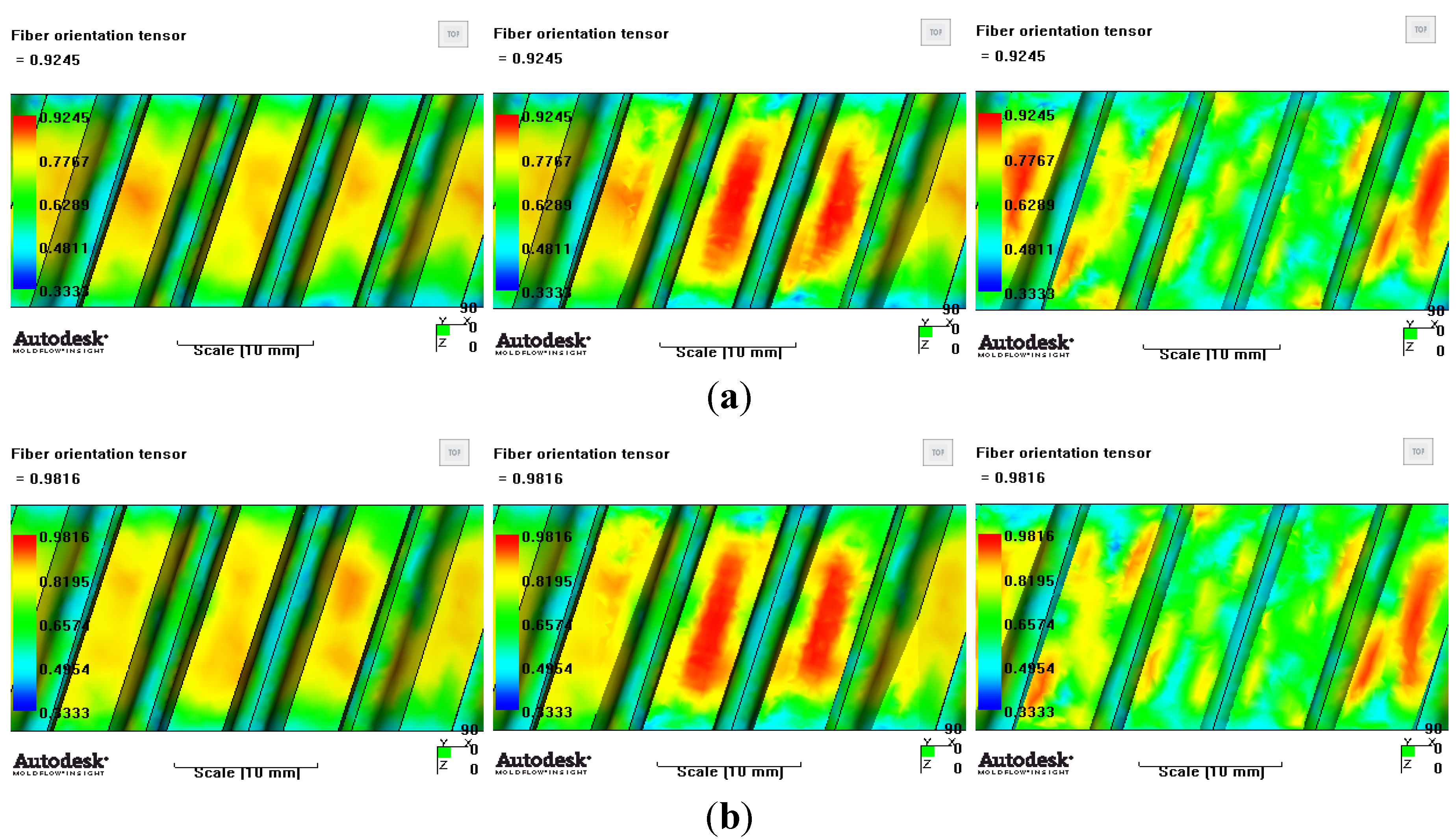
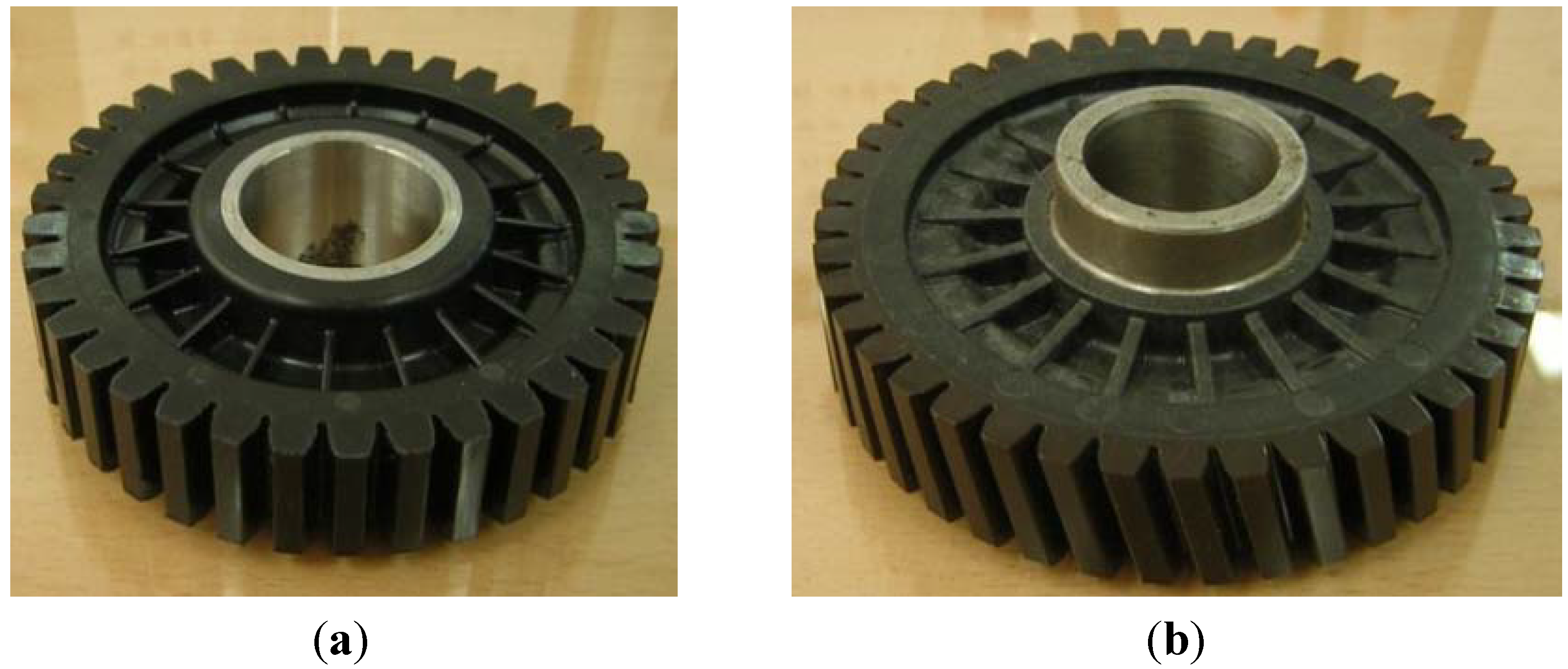
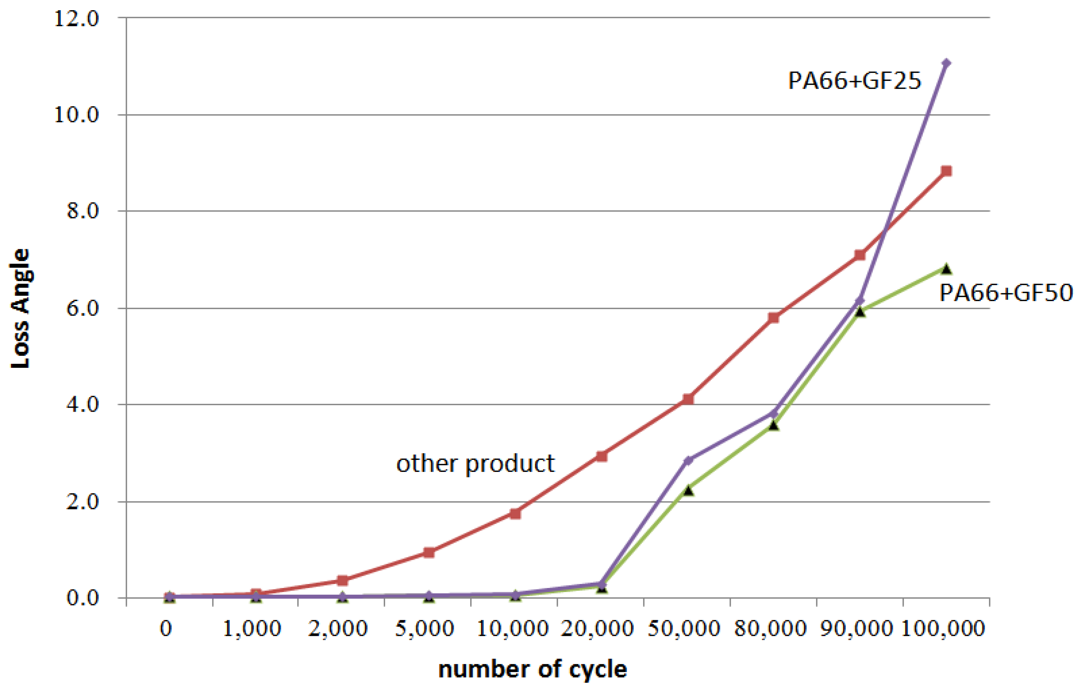
This study aims to design, produce, and evaluate the performance of a plastic worm wheel that can be applied to an MDPS reduction gear module for compact and family sedan vehicles. Prior to the plastic worm wheel design, the worm to be combined with the worm wheel was designed, and so were the corresponding spur and the helical plastic worm wheels. Subsequently, the gear tooth profile and design plan were verified through structural computer-aided engineering (CAE) analysis and the injection mold design and molding process were examined through injection molding CAE analysis. The plastic gear was produced by injection molding with functional engineering plastic resin to which glass fiber reinforcement was added. Lastly, its durability and hardness were evaluated experimentally.

2. Design of Plastic Worm Wheel and Injection Mold

2.1. Design of Plastic Worm Wheel and Structure Analysis

As for the existing gears adopted as automobile parts, only the tooth profile parts are molded with plastic resin, usually with a metal hub inserted. In contrast, this study designs a hub-less type of plastic worm wheel that removes the need for a metal hub, and most of the gear consists of plastic resin. This type of gear is advantageous in terms of its weight-lightening capacity and has no need for a separate heat treatment and finish-cutting process, which reduces the production cost. In addition, this prevents defects due to separation from the metal material, and enhances the accuracy of the tooth profile by skipping the finishing process, as the injection molding covers the complete process of gear tooth profiling. However, it is necessary to design a gear structure that minimizes potential contraction after molding and to secure structural strength. Table 1 shows the specifications and design values of the spur and helical worm wheels designed in this study. Figure 2 shows the plan for the worm wheel to be combined with the designed spur and the helical worm wheels.
Table 1. The hub-less worm wheel specification with spur and helical tooth form.
ItemUNITSpur-typeHelical-type
Pressure angledegree14.514.0
Addendummm−0.36−0.35
Dedendummm2.642.65
Tooth thicknessmm1.571.57
Normal modulemm2.372.28
Helix angledegree0.016.58
Transverse pressure angledegree14.514.58
Tip diametermm92.592.53
Reference diametermm87.888.09
Root diametermm81.7482.02
Base diametermm84.9785.18
Normal tooth thicknessmm5.45.12
Tip radiusmm0.350.35
Base tangent lengthmm20.1326.26
Number of teeth spannedea34
Center distancemm5252
Shaft angledegree7390
Number of teethea3636
Figure 2. Design of worm and worm wheel: (a) worm; (b) worm wheel with helical and spur tooth form.
Materials 06 01873 g002
The worm wheel is applied to the MDPS reduction gear module—the driving power source to assist steering rotation—which adds a constant extra load. Thus, structural stability to compensate for the additional load is required, which is why structural analysis was carried out for the designed worm wheel. Figure 3 shows the 3D model, as well as details of the helical-type of worm wheel structure for structural analysis. The CAE analysis model for the spur and the worm wheel were created in the same method. The structural analysis S/W applied to this study is ABAQUS 6.10. The load condition in the structural analysis was set to 60 N m at the room temperature condition, the maximum torque that may be generated when applied to compact and family sedan vehicles (engine displacement: ~1600–2000 cc). The contact condition between the worm wheel and gear was set to “surface-to-surface”. The tooth form part (Figure 3a), middle locking part (Figure 3b) and end part (Figure 3c) were set to “tie (bonded)” condition. Figure 3d,e shows the CAE analysis model with boundary conditions and finite element model with “tetra-hedra mesh type”. The stress and strain that the gear tooth profile and the glass fiber reinforcement content (weight fraction) added to the polyamide (PA66) material for polymeric worm wheel production were subject to analysis. Table 2 shows the material properties of glass fiber-reinforced polyamide according to glass fiber contents used in this study. A polyamide is highly hygroscopic and the mechanical properties vary according to the moisture absorption. Generally, since the molded products or components with glass fiber-reinforced polyamide are used in various humid environments, the mechanical properties in the moisture condition are considered for securing of product specification. Table 3 shows the stress and strain analysis results of the designed gear tooth profile and frame. As the same amount of torque was applied, the worm and worm wheel tended to make contact at two points, and as the same worm wheel material was used, the contact area of the helical-type of worm wheel was larger. As the contact area was small, the load was concentrated at a certain point, which could be disadvantageous in terms of durability. As to the maximum stress and strain at the tooth profile part, the helical-type indicated 100 MPa, 0.028, and the spur type 120 MPa, 0.03, which shows that the value of the spur type is relatively high. It was the same in the case of the frame part, which indicates that the helical-type of worm wheel is advantageous in terms of worm wheel durability. As to stress and strain analysis results in consideration of the glass fiber reinforcement content, the helical worm wheel was chosen as the subject and the result is shown in Table 4. The maximum stress and strain with a large amount of glass fiber reinforcement content present were relatively small for both the gear tooth profile and the frame parts, and the difference was very small. It is judged, therefore, that as glass fiber reinforcement content increases, the brittleness and strength of the molded part increase accordingly.
Figure 3. Assemble model for strain-stress CAE analysis. (a) tooth form part; (b) middle locking part; (c) end part; (d) tooth, middle locking, end parts and worm gear assembly; (e) boundary and load conditions and finite element model.
Materials 06 01873 g003
Table 2. Material properties of the glass fiber-reinforced polyamide according to fiber contents.
ItemUNITPA66 + GF25 wt %PA66 + GF50 wt %
# Mechanical properties (Cond.)
Tensile creep modulus (1 h)MPa5,00010,000
Tensile creep modulus (10 h)MPa4,1008,000
Charpy impact strength (+23 °C)kJ/m290110
Charpy impact strength (–30 °C)kJ/m24790
Charpy-notched impact strength (+23 °C)kJ/m21220
Charpy-notched impact strength (–30 °C)kJ/m21114
# Thermal properties (Dry)
Melting temperature (10 °C/min)°C263262
Glass transition temperature (10 °C/min)°C8080
Temp. of deflection under load (0.45 MPa)°C260262
Temp. of deflection under load (1.80 MPa)°C245260
Vicat softening temperature (50 °C/h 50N)°C255255
Table 3. Strain-stress comparison analysis of spur vs. helical tooth form worm wheel.
ItemSpur Tooth Form Worm Wheel (PA66 + GF25 wt %)Helical Tooth Form Worm Wheel (PA66 + GF25 wt %)
Tooth Form Part Materials 06 01873 i001 Materials 06 01873 i002
Maximum Stress, Strain120 MPa, 0.03100 MPa, 0.028
Middle Locking Part (Frame) Materials 06 01873 i003 Materials 06 01873 i004
Maximum Stress, Strain118 MPa, 0.02998 MPa, 0.027
Tooth Form Part Materials 06 01873 i005 Materials 06 01873 i006
Maximum Stress, Strain100 MPa, 0.02886 MPa, 0.023
Table 4. Strain-stress comparison analysis according to glass fiber contents.
ItemHelical Tooth Form Worm Wheel (PA66 + GF25 wt %)Helical Tooth Form Worm Wheel (PA66 + GF50 wt %)
Middle Locking Part (Frame) Materials 06 01873 i007 Materials 06 01873 i008
Maximum Stress, Strain98 MPa, 0.02793 MPa, 0.026
End Part (Frame) Materials 06 01873 i009 Materials 06 01873 i010
Maximum Stress, Strain126 MPa, 0.031119 MPa, 0.029

2.2. Design of Injection Mold for Plastic Worm Wheel

The designed plastic worm wheel involves two steps of injection molding, as in Figure 4a. In the first injection molding, the tooth profile part—the gear ring—is molded; the central area of the gearing is removed through the cutting process, and then the worm wheel frame is molded through the second injection molding in which the metal bush combined with the rotation axis and the gear ring produced in the first injection are applied to the insert. This is the general process of making a plastic worm wheel in this study. Figure 4b shows the core and molding plan of the first and second injection molding steps in producing a plastic worm wheel. As the materials applied to the plastic worm wheel in this study include glass fiber reinforcement to secure sufficient strength, the orientation characteristic of the glass fiber reinforcement in reflection of the resin flow are shown. In addition, as the weld mark is likely to weaken the local hardness, the gate location needs to be carefully selected in consideration of the molded part’s function. As for the designed plastic worm wheel, the gate may be put at the center of the wheel or the sides where the tooth profile is located. As the gate is located at the side of the product or the molded part, it may be advantageous regarding the number of cavities, which is related to productivity, but disadvantageous at the same time in that the weld mark is formed at the gear tooth profile part and the glass fiber reinforcement orientation properties become disadvantageous to the worm wheel driving. Thus, this study adopts the top-gate type, as in Figure 4, to secure fiber orientation properties for the load applied to the gear tooth profile. In addition, this prevents the weld line from being formed at the gear tooth profile part.
Figure 4. Injection mold components design for plastic worm wheel fabrication (a) design of injection molding process for plastic worm wheel; (b) design of insert core and mold structure.
Materials 06 01873 g004
In reference to the structural analysis, implemented earlier, with the glass fiber reinforcement content applied, PA66 resin with a glass fiber reinforcement content of either 25 wt % or 50 wt % was applied to the gear ring in the injection molding CAE analysis, and the simulation results for each of the contents of the glass fiber reinforcement were comparatively analyzed. As to the frame part, PA66 resin with a glass fiber reinforcement content of 50 wt % was applied to secure high structural strength, and then the deformation after molding was analyzed. The molding condition applied to the injection molding CAE analysis is shown in Table 5. Figure 5 shows the result of the resin flow analysis that was part of the injection molding CAE analysis carried out on the design. The flow analysis result indicates that both the gear ring and frame parts showed excellent filling tendencies regardless of the type of resin, and that the spur and helical gear rings had the same filling tendencies.
Table 5. Strain-stress comparison analysis according to glass fiber contents.
ItemUNITPA66 + GF25 wt % (Gear ring)PA66 + GF50 wt % (Gear ring, Frame)
Injection times31.5
Packing times2040
Packing pressure%80% of Max. injection pressure80% of Max. injection pressure
Melt temperature°C290290
Mold temperature°C110110
Figure 5. Resin-filling pattern analysis of plastic worm wheel. (a) Injection-filling pattern of spur tooth form worm wheel; (b) Injection-filling pattern of helical tooth form worm wheel; (c) Injection-filling pattern of worm wheel frame part.
Materials 06 01873 g005aMaterials 06 01873 g005b
Generally, the fiber orientation in the resin fluid core layer cannot be controlled by mold structure because the fiber orientation in the core layer changes in the cooling process without pressure. However, the fiber orientation in the skin layer is decided by the consolidation of resin and does not change in the cooling process. In the case when the feature of the gear ring and injection mold structure designed in this study are considered, the principal direction orientation in the part of tooth, that is, the resin flow direction, has a major effect on the stiffness of the plastic worm gear tooth form. The reason is that as many glass fibers to force applied to the pitch surface is large (Figure 6).
Figure 6. Load direction and position in the action of worm wheel.
Materials 06 01873 g006
Figure 7 and Figure 8 show the prediction results of glass fiber principal direction orientation according to the contents of glass fiber reinforcement. If the red color shaded part in the skin layer is large in the analysis result of fiber orientation, it means that the many glass fibers are oriented to the principal direction and the area of loaded. In reference to the fiber orientation analysis, the fiber principal direction orientation of tooth part in the skin layer is large in the PA66 resin with glass fiber reinforcement content of 25% because the resin fluid in the case of glass fiber reinforcement content of 50% cannot make relatively good progress. However, all cases have poor distribution of glass fiber in the part of the dedendum circle. This result means that the tooth root part of worm wheel may be vulnerable to the force applied to worm wheel teeth compared with the pitch surface part. As to the deformation analysis in connection with the measurement accuracy of the final molded part, the spur and helical gear rings showed the same level of deformation (Table 6).
Figure 7. Glass fiber orientation analysis of spur worm wheel: (a) Upper, center and low layer from the top of tooth (PA66 + GF25 wt %); (b) Upper, center and low layer from the top of tooth (PA66 + GF50 wt %).
Materials 06 01873 g007
Figure 8. Glass fiber orientation analysis of helical worm wheel: (a) Upper, center and low layer from the top of tooth (PA66 + GF25 wt %); (b) Upper, center and low layer from the top of tooth (PA66 + GF50 wt %).
Materials 06 01873 g008
Table 6. Deformation values of X-, Y-, and Z-directions.
ItemX-directionY-directionZ-direction
PA66 + GF25 wt % Spur-type gear ring Materials 06 01873 i011 Materials 06 01873 i012 Materials 06 01873 i013
Max. 0.67 mmMax. 0.66 mmMax. 0.16 mm
PA66 + GF25 wt % Helical-type gear ring Materials 06 01873 i014 Materials 06 01873 i015 Materials 06 01873 i016
Max. 0.64mmMax. 0.65mmMax. 0.14mm
PA66 + GF50 wt % Spur-type gear ring Materials 06 01873 i017 Materials 06 01873 i018 Materials 06 01873 i019
Max. 0.43mmMax. 0.41mmMax. 0.12mm
PA66 + GF50 wt % Helical-type gear ring Materials 06 01873 i020 Materials 06 01873 i021 Materials 06 01873 i022
Max. 0.49mmMax. 0.37mmMax. 0.1mm

3. Injection Molding Process and Evaluation of Plastic Worm Wheel

Table 7 shows the injection molding conditions to produce the sample of spur and helical-type worm wheels. The injection mold conditions were determined in reference to the injection molding CAE analysis. In the case of the gear ring, the conditions were the same as those of the structural and injection molding CAE analysis: the glass fiber-reinforced content was 25 wt % (Minlon 73GM40, DuPont Inc., Ulsan, Republic of Korea) and 50 wt % (Durethan AKV50H2.0, LANXESS), and 50 wt % in the case of injection mold for the frame part with the gear ring as the insert. Figure 9 shows images of the spur and helical worm wheels produced through injection molding as samples. Table 8 shows the material properties of plastic resin used in plastic worm wheel teeth part and teeth strength measured by the exclusive test system. In the case of the teeth strength test, the load-cell data measured when the tooth of worm wheel is broken after assembling the worm gear and worm wheel in the test system. Average strength of teeth part is about 900 kgf/cm2, measured using the teeth strength test system (Figure 10).
Table 7. Detailed injection molding conditions for plastic worm wheel.
ItemUNITPA66 + GF25 wt %PA66 + GF50 wt %
Injection machine capacityton300300
Cylinder diameterØ5555
Maximum injection pressurekgf/cm2724724
Temperature°C270–290270–290
Injection pressurekgf/cm2140140
Injection times31.5
Packing times2040
Mold temperature°C110110
Holding pressurekgf/cm2140140
Cooling times120120
Figure 9. Plastic worm wheels manufactured by injection molding. (a) Plastic worm wheel with spur tooth form; (b) Plastic worm wheels manufactured by injection molding.
Materials 06 01873 g009
Table 8. Material properties of plastic worm wheel prototype (teeth part, PA66 + GF25 wt %).
ItemUNITPrototype 1Prototype 2
Hardness(external part)HRM101100
Hardness(internal part)HRM9798
Specific gravity1.321.32
Young’s modulus×109 N/m28585
Coefficient of expansionμm/°C0.420.42
Teeth’s strengthkgf/cm2926865
Figure 10. Teeth strength of worm wheel test system.
Materials 06 01873 g010
As the worm wheel delivers power generated by the motor in order to assist with steering, this might cause the car steering function to be lost upon excessive backlash or damage. Thus, it is vital to conduct a durability evaluation for the applied load. As shown in Table 9, therefore, a system to measure the backlash that might take place during worm wheel operation was developed, and durability with 100,000 repetitions of the same operation was evaluated. The durability evaluation was conducted for the helical-type worm wheels that were judged advantageous in terms of maximum stress and strain after the structural analysis described in the previous section. The existing common worm wheels of high-viscosity resin and the sample worm wheels that contained 25 wt % or 50 wt % glass fiber reinforcement content in this study were comparatively analyzed in terms of backlash occurrence. Figure 11 shows a graph of backlash extents according to the number of repetitions of the operation. While existing worm wheels of high-viscosity resin tended to show a drastic increase of wheel backlash after the 1000th operation, the worm wheel with glass fiber reinforcement showed an increase of wheel backlash after the 20,000th operation. In the case of the worm wheel of 25 wt % glass fiber reinforcement content, however, the wheel backlash increased a great deal more than the worm wheel of high-viscosity resin after the 90,000th operation. It is judged that this resulted from the crack at the gear tooth profile, as in Table 10.
Table 9. Durability test conditions of worm wheel.
ItemUNITVALUEPhoto of test system
Temperature°C23 Materials 06 01873 i023
Humidity%55
Velocitycpm6
LoadNm60
Rotation degreedegree±540
Cycle(No-pause)cycle100,000
Temperature°C23
Number of articleea2
Figure 11. Variation of plastic worm wheel loss angle according to cycle.
Materials 06 01873 g011
Table 10. Surface images of plastic worm wheel tooth part according to cycle.
ItemPA66 + GF25 wt %PA66 + GF50 wt %
Internal organization Materials 06 01873 i024 Materials 06 01873 i025
Glass Fiber Feature (Diameter 6–8 μm, Length 120–160 μm) Materials 06 01873 i026 Materials 06 01873 i027
Surface after 5000 cycle Materials 06 01873 i028 Materials 06 01873 i029
Surface after 30,000 cycle Materials 06 01873 i030 Materials 06 01873 i031
Surface after 50,000 cycle Materials 06 01873 i032 Materials 06 01873 i033
Fracture face Materials 06 01873 i034 Materials 06 01873 i035
The difference in wheel backlash according to glass fiber reinforcement content is shown in the surface images of the gear tooth profile in Figure 12. As in the graph in Figure 11, the operation of the worm wheel of 25 wt % glass fiber reinforcement content caused wheel backlash to a relatively large degree after the 50,000th operation, which is also indicated in Figure 9 and shows the extent of the surface crack at the gear tooth profile after the 50,000th operation. Thus, in the durability evaluation, it turned out that worm wheels with glass fiber reinforcement are advantageous compared to those of high-viscosity resin, and that worm wheels of 50 wt % glass fiber reinforcement content are the most advantageous in terms of durability.
Figure 12. Fracture and crack generation in the durability test.
Materials 06 01873 g012

4. Summary and Discussion

This study develops and evaluates the durability of the plastic worm wheel of a MDPS reduction gear applicable to compact and family sedan vehicles. In the case of plastic worm wheels, the strength and hardness are comparatively inferior to those of metal materials, while they are advantageous in terms of light weight, vibration and noise reduction, and corrosion resistance. Thus, plastic materials with glass fiber reinforcement added were applied to worm wheel production, which was followed by structural analysis and injection molding CAE analysis. As to the structural analysis, it turned out that the helical-type worm wheel is relatively advantageous in terms of the maximum stress and strain in application of the plastic worm wheel tooth profile and the adopted materials. Based on the result of structural analysis, worm wheel materials that were advantageous in terms of structure were chosen, and injection molding CAE analysis was implemented. As a result, it turned out that the worm wheel of 50 wt % glass fiber reinforcement content was advantageous in terms of deformation, which has a great effect on the operation of the worm wheel. After the CAE analysis, an injection mold was produced that was, in turn, used to produce a plastic worm wheel. Finally, a durability evaluation on the worm wheel backlash in relation to glass fiber reinforcement content and in comparison with existing high-viscosity resin worm wheels was implemented. that the findings demonstrated that the helical worm wheel of 50 wt % glass fiber reinforcement content is relatively advantageous in terms of performance.
Based on the CAE analysis and the results of the tests conducted in this study, it was shown that as glass fiber reinforcement content increases, strength and hardness potentially improve, but damage may result from the shock due to fluctuating external force as the brittleness also increases. In addition, as the distribution of glass fiber reinforcement is not even, the strength and hardness of the worm wheel tooth profile might change, which results in quality deterioration. Therefore, future study needs to address injection mold and molding techniques that can secure stable fabric distribution and orientation in addition to methods that ease the determination of the amount of glass fiber reinforcement best suited for the performance of the worm wheel.

Acknowledgments

This research is supported by the production technology development project of Korea Institute of Industrial Technology (KITECH).

References

  1. Kim, J.T.; Yoo, J.M.; Kim, K.W. Simulation Study on the Vibration Caused by Motor in MDPS System. In Proceedings of the KSAE Annual Conference, Songdo Convensia, Korea, 24 November 2009.
  2. Imrek, H. Performance improvement method for Nylon 6 spur gears. Tribol. Int. 2009, 42, 503–510. [Google Scholar] [CrossRef]
  3. Mouti, Z.; Westwood, K.; Kayvantash, K.; Njuguna, J. Low velocity impact behavior of glass filled fiber-reinforced thermoplastic engine components. Materials 2010, 3, 2463–2473. [Google Scholar] [CrossRef] [Green Version]
  4. Mendi, F.; Can, H.; Kulekci, M.K. Fatigue properties of polypropylene involute rack gear reinforced with metallic springs. Mater. Design 2006, 27, 427–433. [Google Scholar] [CrossRef]
  5. Duzcukoglu, H. Study on development of polyamide gears for improvement of load-carrying capacity. Tribol. Int. 2009, 42, 1146–1153. [Google Scholar] [CrossRef]
  6. Hirogaki, T.; Aoyama, E.; Katayama, T.; Iwasaki, S.; Yagura, Y.; Sugimura, K. Design systems for gear elements made of cotton fiber-reinforced plastics. Compos. Struct. 2004, 66, 47–52. [Google Scholar] [CrossRef]
  7. Hoskins, T.J.; Dearn, K.D.; Kukureka, S.N.; Walton, D. Acoustic noise from polymer gears—A tribological investigation. Mater. Design 2011, 32, 3509–3515. [Google Scholar] [CrossRef]
  8. Senthilvelan, S.; Gnanamoorthy, R. Damping characteristics of unreinforced, glass and carbon fiber reinforced nylon 6/6 spur gears. Polym. Test. 2006, 25, 56–62. [Google Scholar] [CrossRef]
  9. Senthilvelan, S.; Gnanamoorthy, R. Influence of reinforcement on composite gear metrology. Mech. Mach. Theory 2008, 43, 1198–1209. [Google Scholar] [CrossRef]
  10. Mao, K.; Li, W.; Hooke, C.J.; Walton, D. Friction and wear behavior of acetal and nylon gears. Wear 2009, 267, 639–645. [Google Scholar] [CrossRef]

