Microstructure and Tensile Behavior of Laser Arc Hybrid Welded Dissimilar Al and Ti Alloys

Abstract
: Fiber laser-cold metal transfer arc hybrid welding was developed to welding-braze dissimilar Al and Ti alloys in butt configuration. Microstructure, interface properties, tensile behavior, and their relationships were investigated in detail. The results show the cross-weld tensile strength of the joints is up to 213 MPa, 95.5% of same Al weld. The optimal range of heat input for accepted joints was obtained as 83–98 J·mm−1. Within this range, the joint is stronger than 200 MPa and fractures in weld metal, or else, it becomes weaker and fractures at the intermetallic compounds (IMCs) layer. The IMCs layer of an accepted joint is usually thin and continuous, which is about 1μm-thick and only consists of TiAl2 due to fast solidification rate. However, the IMCs layer at the top corner of fusion zone/Ti substrate is easily thickened with increasing heat input. This thickened IMCs layer consists of a wide TiAl3 layer close to FZ and a thin TiAl2 layer close to Ti substrate. Furthermore, both bead shape formation and interface growth were discussed by laser-arc interaction and melt flow. Tensile behavior was summarized by interface properties.1. Introduction
Growing concerns about weight reduction and rare metal saving have stimulated the joining of dissimilar metals. Joining aluminum (Al) and titanium (Ti) alloys is of interest to meet the requirement of high strength and low weight in aeronautic and automotive industries. For example, a wing made of Ti alloy is required to be fastened to Al fuselage in airplane fabrication. The challenges of Al/Ti joining come from the formation of brittle Al/Ti intermetallic compounds (IMCs) and characteristic difference between the two metals [1–4]. The melting points of Ti and Al are 1667 °C and 660 °C, respectively; the thermal conductivities of Ti and Al are 21.6 W·m−1·K−1 and 238 W·m−1·K−1, respectively; the thermal expansion coefficients of Ti and Al are 8.9 × 10⁻⁶ K−1 and 23.5 × 10⁻⁶ K−1, respectively. Precise thermal input is then necessary to solve the problems caused by these differences in thermal characterization, as well as the growth brittle Al/Ti IMCs.
Diffusion bonding and brazing [5–7] have been widely studied to join Al to Ti alloys, but special joint configuration and whole heating limited their use in flexible fabrication. Friction stir welding has been attempted to join Al and Ti alloys in recent years [8–10]. However, the maximum failure load is only up to 62% that of Al base metal, indicating the need of further improvement. Laser welding would be an attractive and preferred fusion processes due to its precise power output, high welding speed and excellent flexibility [11,12]. To join dissimilar metals, a so–called laser welding–brazing has been developed [13–19], by which the IMCs growth was suppressed effectively because the alloy with high melting point is only brazed by melted alloy with low melting point. The tensile strength of laser welding-brazed Al/Ti joints is up to 290 MPa [13–15], showing a great potential. However, high reflection of Al to laser beam is a question when using this technique to join Al alloys with other metals [20,21]. It dramatically decreases the utilization efficiency of the laser beam. Therefore, it is necessary to increase laser power to suppress the reflection effect to guarantee process stability during laser welding of Al alloys.
Laser-arc hybrid welding could suppress high reflection effect of Al alloys to laser beam via arc preheating or pre-melting of base metal. Furthermore, it increases welding efficiency, stabilizes the process and improves joint quality by laser-arc synergic effect [22–25]. Meanwhile, a new arc process of cold metal transfer (CMT) that combines welding electric parameters and wire motion at the same time was developed recently [26,27]. The wire motion gives the wire a back-drawing force when liquid droplet come into contact with the weld pool, resulting in the material transfer during CMT process taking place with barely any flow of current. As a result, CMT welding has much lower heat input than classic metal inert gas (MIG) arc welding, and is free of spatter. Compared with conventional hybrid welding technique, therefore, laser-CMT arc hybrid welding has more advantages in stabilizing process and reducing heat input, and is also more effective at joining dissimilar Al and Ti alloys. Unfortunately, no prior work was addressed on this area. The attention of the present study was focused on this work to reveal the joint characterization of laser-CMT hybrid welding of dissimilar Al and Ti alloys.
2. Experimental Procedures
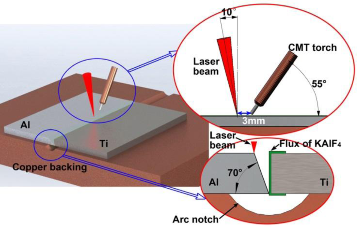
The hybrid welding system integrated a fiber laser and a Fronius CMT welder. The laser beam was transmitted by a 200 μm core–diameter fiber, collimated by a lens with 150 mm focal length and focused by a lens with 250 mm focal length. The beam diameter at focus spot is about 0.3 mm. The materials used were 6061-T6 Al alloy (AA6061) and Ti-6Al-4V alloy (Ti6Al4V). Both of them are 2.0 mm thick. All the samples were machined at the size of 100 × 50 mm2. The Al sheet was prepared with a bevel 20° groove as shown in Figure 1, while Ti sheet was prepared as I groove. Preliminary experiment showed that when the offset of laser beam and the arc to the edge of Al sheet groove is too large, the Ti sheet, especially the root cannot be covered, and underfill appears on the weld surface. When the laser beam and the arc are too close to the Ti sheet, the joint cannot be formed, and was fractured directly due to fast formation of IMCs layer. Therefore, in this paper, both focused laser beam and the wire tip from the weld torch were set to act on the edge of the Al sheet bevel during welding.
Table 1 shows the mass chemical compositions of base materials and filler wire with diameter of 1.2 mm. Figure 1 also shows the arrangement of laser beam and CMT torch, which were optimized by previous study [28]. The angles of laser beam and weld torch to workpiece surface were 80° and 55° respectively. The distance between laser beam and wire tip (DLA) was 3 mm. A copper backing with a circular arc (radius 6 mm and depth 1 mm) was used to force the formation of weld root. The welding parameters of typical joints used for microstructure and evaluating mechanical properties are shown in Table 2. The shielding gas of CMT torch is argon with flow rate 30 L·min−1. The laser beam is irradiated on the edge of the bevel of the Al sheet during welding.
Before welding, the sample groove was cleaned by acetone. A Nocolok flux (KAlF4) was coated homogenously on the groove of Ti alloy with the thickness of approximately 20–30 μm. After welding, the metallurgical samples were prepared by standard procedures. The metallurgical samples were etched by Keller’s reagent (1–3 mL HF + 2–6 mL HNO3 + 91–97 mL H2O) with etching time 3 s for microstructure examination of fusion zone (FZ), but were just polished for microstructure examination of FZ/Ti-6Al-4V interface. The bead shape and microstructure were observed using optical microscope and scanning electron microscopy (SEM, FEI company, Hillsboro, TX, USA). The chemical compositions of IMCs layer were analyzed using energy dispersive spectrometer (EDS, FEI company, Hillsboro, TX, USA). According to the ISO standard of 6892-1:2009 [29], rectangle cross-weld tensile samples were prepared with the size of 100 mm in length and 15 mm in width, and were tested at room temperature with a travel speed of 1 mm·min−1. Two samples cut from one joint were tested for tensile strength, and the test results and their average are listed in Table 2. The fracture surfaces of the joints cracking at IMCs layer were tested by X-ray diffraction (XRD, PANalytical B.V., Almelo, The Netherland) to identify interface phases. Here, the scanning speed of XRD test was 5° per minute, and the scanning range was 10° to 100°. The whole fracture surface 15 × 2 mm2 was scanned.
3. Results
3.1. Bead Shape
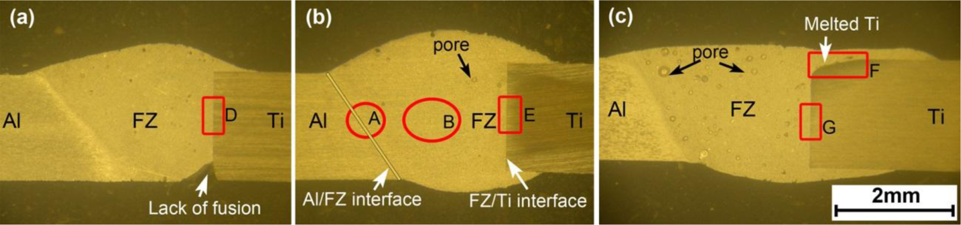
In Figure 2, the joints show a typical welding–brazing characteristic [30]. The AA6061 is welded, while the Ti6Al4V is brazed with liquid pool by atomic diffusion. When the heat input is too small, for example the joint #1 with heat input of 71 J·mm−1 (Figure 2a), lack of fusion appears at the root of FZ/Ti6Al4V interface. Figure 2b shows this defect can be avoided by increasing heat input. Besides, the FZ/Ti6Al4V interface remains linear as dies the original edge of Ti6Al4V sheet when the heat input is appropriate, indicating that the Ti6Al4V sheet is not melted and is just brazed with the liquid pool. When the heat input increases to 107 J·mm−1, the top corner of the Ti6Al4V sheet is melted, as shown in Figure 2c.
3.2. Microstructure and Interface Properties
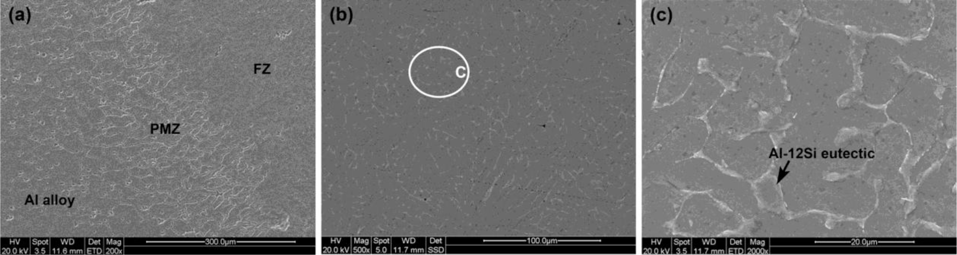
Figure 3 shows the AA6061 and the FZ are bridged by a partial melted zone (PMZ), while the FZ is composed of equiaxial dendrites consisting of α-Al matrix and a small amount of precipitates in grain boundaries. The precipitates are identified as Al-12Si eutectic by EDS test, which is also observed in previous literatures [13–15].
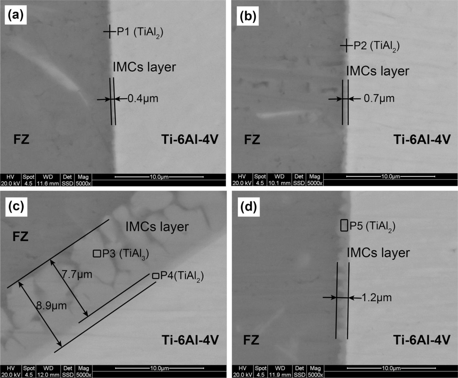
Figure 4 shows that the IMCs layer is thickened by increasing heat input or laser power. The thickness of IMCs layer at the middle of the interface increases from 0.4 to 0.7 and 1.2 μm, by nearly 3-fold when the heat input increases from 71 to 107 J·mm−1. Figures 4a,b show that the IMCs layer is thin, uniform and regular when the interface is not melted. However, non-uniformity of IMCs layer is found between the top corner and other areas when the heat input is too large. For example, for joint #4 with heat input of 107 J·mm−1 (Figure 4c,d), the IMCs layer thickness at the melted top corner is 8.9 μm, nearly 7.5 times thicker than that at the middle.
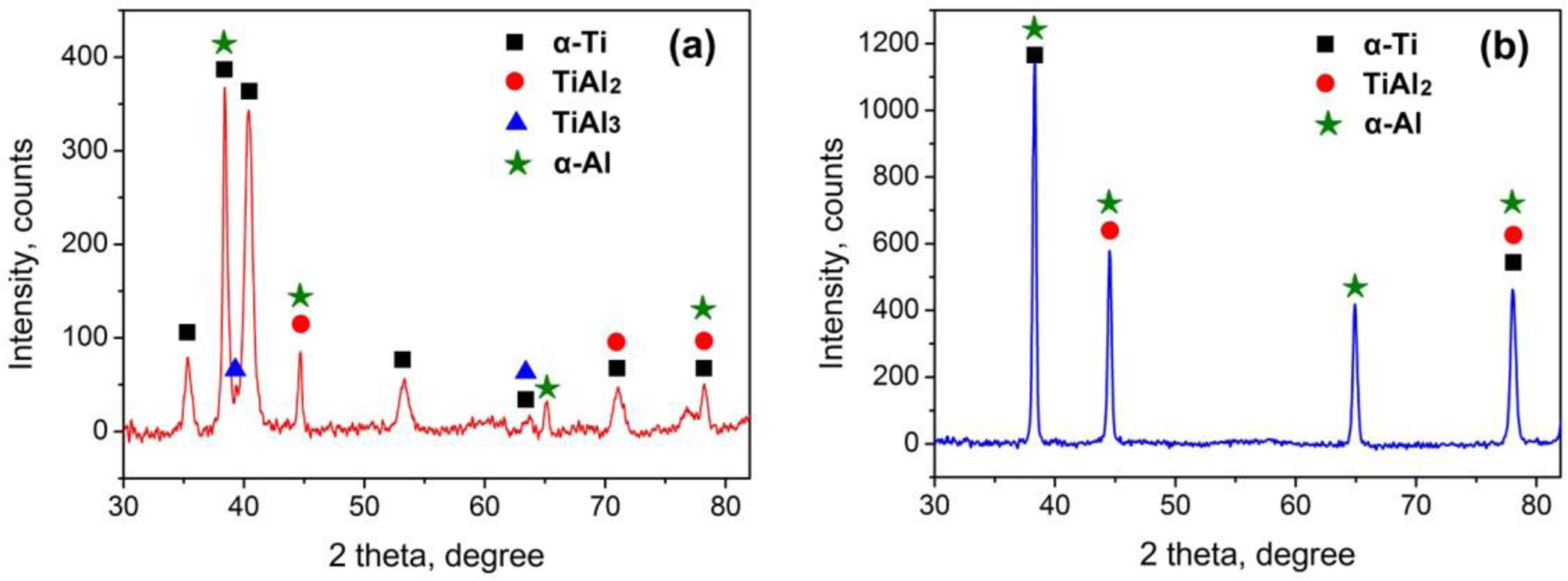
It is also found that the thick IMCs layer at melted top corner consists of two layers: a narrow continuous layer close to the Ti6Al4V substrate and a wide discontinuous layer close to FZ. However, the thin IMCs layer only consists of one layer. Figure 5a gives the XRD results of joint #4. Both TiAl3 and TiAl2 were examined in the thick IMCs layer. Table 3 shows the atomic molar ratio of Ti and Al. The wide discontinuous layer and continuous thin layer in Figure 4c agree well with that of TiAl3 and TiAl2, respectively. The molar ratio of Al and Si atoms is calculated together because Si atoms substitute Al atoms in the TiAl3 and TiAl2 ordered structures during the growth of the IMCs layer. The chemical compositions are in accord with the XRD results. Therefore, the wide layer close to the FZ in this excessively growing IMCs layer is TiAl3 layer, and the thin layer close to the Ti6Al4V sheet is the TiAl2 layer. Besides, the thin IMCs layers in Figure 4a,b,d are identified as TiAl2 layers because only TiAl2 was examined by XRD test in Figure 5b and the atomic molar ratio in these IMCs layer also agrees with that of TiAl2.
3.3. Tensile Strength and Fractograph
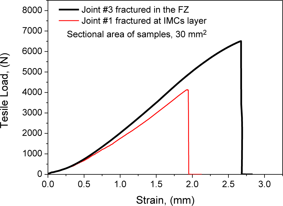
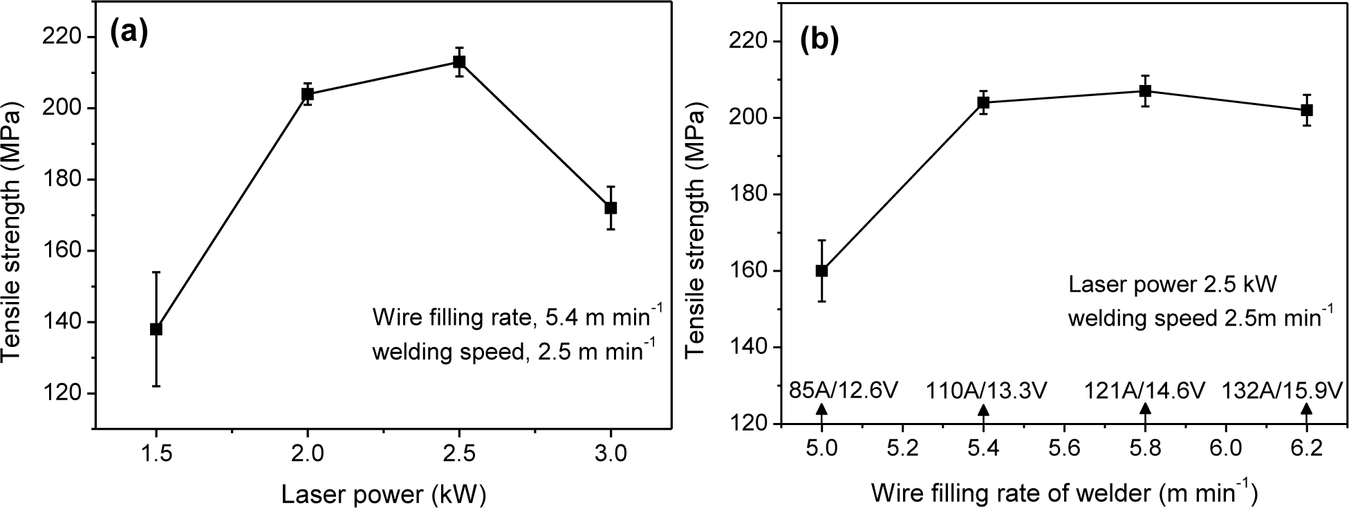
Figure 6 gives the load-strain curves of typical joints. Figure 7 shows cross-weld tensile strength is up to 213 MPa, 95.5% that of laser-CMT welded 2 mm thick AA6061 (223 MPa) [31]. Figure 7a shows that the strengths are above 200 MPa when laser power is at the range of 2.0–2.5 kW, but decrease rapidly when laser power deviates from this range. Figure 7b shows the strengths are higher than 200 MPa when wire filling rate (corresponding to arc current) increases to 5.4 m·min−1 or higher. This indicates that tensile strength is more sensitive to laser power. The other interesting observation is that the test error keeps a low level when tensile strength is higher than 200 MPa.
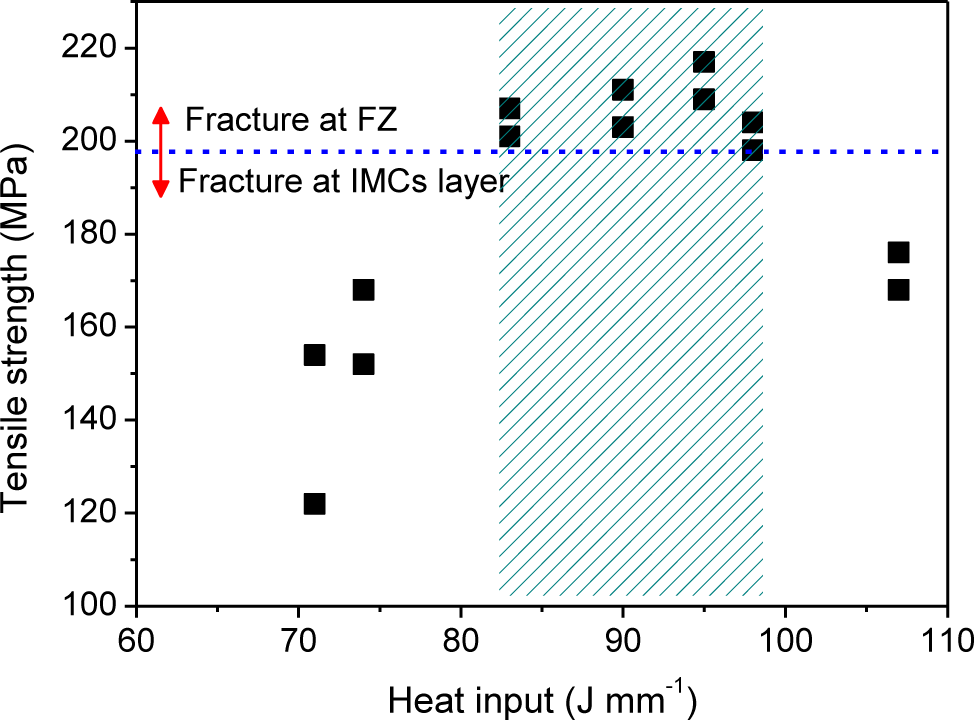
Figure 8 shows the relationship between heat input and tensile strength. It is found that the optimal range of heat input is 83–98 J·mm−1. Within this range, all joints are stronger than 200 MPa and fracture in the FZ. Beyond this range, the joint are weaker than 200 MPa and fracture in the IMCs layer. When the heat input decreases to 71 J·mm−1, the tensile strength reduces to the minimum, only 138 MPa.
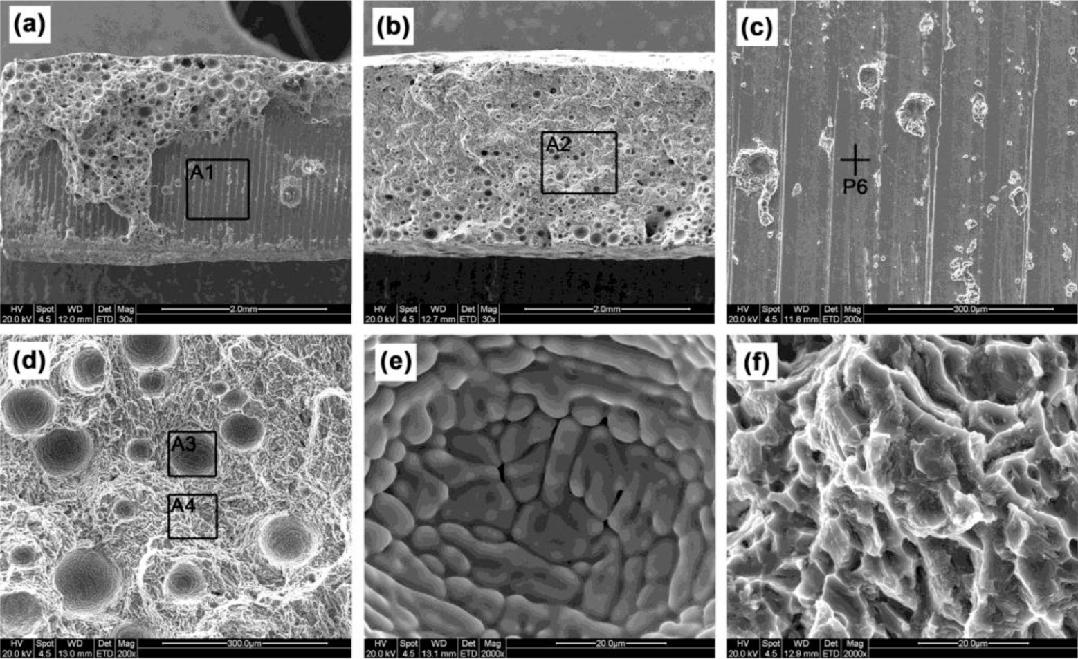
In Figure 9a, a large scale of a plane appears on the fracture surface of joint #1 with the defect of lack of fusion. The atomic molar percentage of the plane (point P6 in Figure 9c) is 77.41Ti-21.09Al-1.5Si (at%), suggesting it is Ti6Al4V substrate because no Ti3Al is found in the XRD test. It denotes that at this stage a crack initiates between the IMCs layer and the substrate. In Figure 9b, many pores appear on the fracture surface of the joint cracking in the FZ, which would be the crack initiation of these joints. According to the spherical shape in Figure 9d and round-tip dendrites in Figure 9e [32], the pores should be hydrogen pores. Figure 9f shows that the fracture surface of FZ is characterized by tearing ridges and a few dimples, representing a typical brittle feature.
4. Discussion
4.1. Bead Shape Formation and Interface Growth
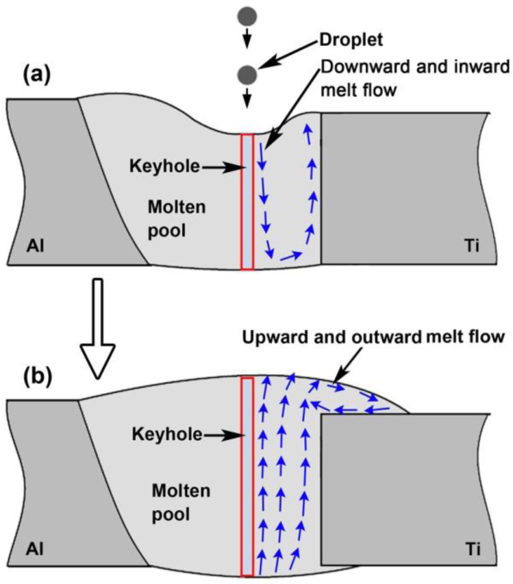
Previous literatures reported that at the beginning of molten pool formation during laser-arc hybrid welding, the liquid metal is moving downward and inward by droplet impact force and plasma recoil force, and the pool surface is sunken, as shown in Figure 10a [33,34]. The downward and inward melt flow drives arc heat into the lower part of molten pool, resulting in a more homogenous pool. At the subsequent stabilization stage, as show in Figure 10b, the melt flow is outward and upward from the keyhole root to the margin of the molten pool by surface tension, buoyancy and backflow of sunken liquid metal. This upward and outward flow plays a big role in the formation of bead shape. On the other hand, it was well known that the laser is a primary factor determining molten pool depth of hybrid welding due to the deep penetrating keyhole [22–24]. The bigger the laser power is, the deeper the molten pool is. That is, arc heat mainly influences the upper pool, but laser heat influences the whole pool because laser keyhole is throughout molten pool. These findings denote that the interface reaction between molten pool and Ti sheet, especially the lower part depends on the laser, although some arc heat is driven into the lower part by melt flow. This leads to the result that the IMCs layer formation is more sensitive to laser power.
Given the above-mentioned viewpoints, bead shape formation and interface growth under different laser power can be explained as follows.
When laser power is appropriate, as shown in Figure 11a, both the volume of liquid metal generated by heat input and the depth of outward and upward flow are sufficient to fully cover the Ti sheet. This causes an accepted joint without root defect. Meanwhile, a sufficient interface reaction is achieved due to enough heat input, resulting in an IMCs layer with appropriate thickness. At this stage, the formation process of IMCs layer is illustrated in Figure 11d. Some Ti atoms first dissolve into molten pool during the heating stage. Subsequently, dissolved Ti atoms react with Al atoms to form TiAl2 along a liquid/solid interface. The formation of TiAl3 is suppressed, which would be attributed to fast cooling rate of hybrid welding since the welding speed used in this paper (2.5 m·min−1) is even faster than that of the usual single arc and laser welding (<0.3 m·min−1) [15,16].
When laser power is inadequate, the laser keyhole obtained is shallow and the volume of melted metal in lower part is not enough because of insufficient heat input. As shown in Figure 11b, the melt flow is above the root of Ti6Al4V sheet, and do not full cover it. Lack of fusion then forms at the root. It also causes a too thin IMCs layer because of smaller amount of dissolved Ti atoms and faster solidification rate.
When laser power is excessive, as shown in Figure 11c, the top corner of Ti6Al4V sheet is melted as a curve due to excessive heat accumulation at here. Figure 11e shows melted Ti6Al4V affords more Ti atoms at the front of liquid/solid interface. Meanwhile, the accumulated heat here leads to a slow solidification rate which makes dissolved Ti atoms move farther away from the substrate. These factors cause a stronger interface reaction, and then a far thicker IMCs layer. Besides, slow solidification rate improves the formation of TiAl3 by extending reaction time. The interface growth can be described as follows. First, dissolved Ti atoms react with Al atoms to form a TiAl2 layer. Second, the reaction L + TiAl2 → TiAl3 occurs to form TiAl3 layer as temperature decreases. Although in one joint, the middle of interface remains solid and then gets a thin TiAl2 layer because no heat accumulation occurs here.
4.2. Tensile Behavior
Usually, tensile properties of welded joint are related to bead shape and IMCs layer. When heat input is appropriate, the joints have accepted tensile strength (more than 200 MPa). At this stage, the porosity in the FZ rather than the thin and continuous IMCs layer becomes the weakest zone of the joint, resulting in the joint being fractured in the FZ. When heat input or laser power is inadequate, lack of fusion appears at the root of interface, and meanwhile the IMCs layer is too thin. During the tensile test, the crack prefers to initiate at the gap caused by lack of fusion due to stress concentration, and then propagates to IMCs layer to peel the IMCs layer off the Ti6Al4V substrate. This fracture behavior reduces the joint strength, and causes the fracture surface characterized by a large scale of the Ti6Al4V plane. Accordingly, a too thick and discontinuous IMCs layer forms at the melted top corner of the FZ/Ti6Al4V interface when heat input is excessive. This excessively thick IMCs layer is harmful to joint strength because stress concentration easily occurs between brittle IMCs. Therefore, for these joints with excessive heat input, the crack prefers to initiate in the thick and brittle IMCs layer at the top corner of the FZ/Ti6Al4V interface. This reduces the strength of these joints and makes a fracture at the IMCs layer.
5. Conclusions
Fiber laser-cold metal transfer arc hybrid welding was developed to join a Ti6Al4V Ti alloy to an AA6061 Al alloy in butt configuration. The optimal range of heat input for the accepted joint was obtained, which is 83–98 J·mm−1. The cross–weld tensile strength is up to 213 MPa, 95.5% that of hybrid welded 6061-T6 Al alloy. Within the optimal range of heat input, accepted joints are stronger than 200 MPa and fracture in the FZ. Otherwise, the joints are lower than 200 MPa, and fracture in the IMCs layer because of the shape defects or too thick IMCs layer.
It was found that both the bead shape formation and the interface growth depend on the downward and upward flow in the molten pool, which is dominated by the laser power and the volume of liquid metal generated by heat input. When the laser power is too small, lack of fusion appears at the root of the Ti6Al4V sheet due to insufficient liquid metal and shallow flow. When the laser power or the heat input is excessive, a too thick IMCs layer forms at the top corner of the FZ/Ti6Al4V interface because the substrate here is melted and the solidification rate is slowed by heat accumulation.
The IMCs layer of accepted joint is thin and continuous, and only consists of TiAl2 due to fast solidification rate of hybrid welding. The thickness is about 1 μm. However, the IMCs layer is rapidly thickened when the Ti6Al4V sheet is melted, which occurs at the top corner of the Ti6Al4V sheet as the heat input is excessive. At this moment, there are two layers, the wide TiAl3 layer close to the FZ and the thin TiAl2 layer close to the Ti6Al4V sheet.
Acknowledgments
The authors gratefully acknowledge the financial supports from the National Natural Science Foundation of China with grant No. 51275186.
Conflicts of Interest
The authors declare no conflict of interest.
References
- Majumdar, B.; Galun, R.; Weisheit, A.; Mordike, B.L. Formation of a crack-free joint between Ti alloy and Al alloy by using a high-power CO2 laser. J. Mater. Sci 1997, 32, 6191–6200. [Google Scholar]
- Kreimeyer, M.; Wagner, F.; Vollertsen, F. Laser processing of aluminum-titanium-tailored blanks. Opt. Lasers Eng 2005, 43, 1021–1035. [Google Scholar]
- Sambasiva, R.A.; Madhusudhan, R.G.; Satya, P.K. Microstructure and tensile properties of dissimilar metal gas tungsten arc welding of aluminium to titanium alloy. Mater. Sci. Technol 2011, 27, 65–70. [Google Scholar]
- Vaidya, W.V.; Horstmann, M.; Ventzke, V.; Petrovski, B. Improving interfacial properties of a laser beam welded dissimilar joint of aluminium AA6056 and titanium Ti6Al4V for aeronautical applications. J. Mater. Sci 2010, 45, 6242–6254. [Google Scholar]
- Takemoto, T.; Okamoto, I. Intermetallic compounds formed during brazing of titanium with aluminium filler metals. J. Mater. Sci 1988, 23, 1301–1308. [Google Scholar]
- Ren, J.W.; Li, Y.J.; Feng, T. Microstructure characteristics in the interface zone of Ti/Al diffusion bonding. Mater. Lett 2002, 56, 647–652. [Google Scholar]
- Sohn, W.H.; Bong, H.H.; Hong, S.H. Microstructure and bonding mechanism of Al/Ti bonded joint using Al-10Si-1Mg filler metal. Mater. Sci. Eng. A 2003, 355, 231–240. [Google Scholar]
- Chen, Y.C.; Nakata, K. Microstructural characterization and mechanical properties in friction stir welding of aluminum and titanium dissimilar alloys. Mater. Des 2009, 30, 469–474. [Google Scholar]
- Kim, Y.C.; Fuji, A. Factors dominating joint characteristics in Ti-Al friction welds. Sci. Technol. Weld. Join 2002, 7, 149–154. [Google Scholar]
- Fuji, A.; Ikeuchi, K.; Sato, Y.S.; Kokawa, H. Interlayer growth at interfaces of Ti/Al-1%Mn, Ti/Al-46%Mg and Ti/pure Al friction weld joints by post-weld heat treatment. Sci. Technol. Weld. Join 2004, 9, 507–512. [Google Scholar]
- Wang, Z.M.; Gao, M.; Tang, H.G. Characterization of AZ31B wrought magnesium alloy joints welded by high power fiber laser. Mater. Charact 2011, 62, 943–951. [Google Scholar]
- Gao, M.; Tang, H.G.; Chen, X.F.; Zeng, X.Y. High power fiber laser arc hybrid welding of AZ31B magnesium Alloy. Mater. Des 2012, 42, 46–54. [Google Scholar]
- Chen, S.H.; Li, L.Q.; Chen, Y.B.; Dai, J. Improving interfacial reaction nonhomogeneity during laser welding-brazing aluminum to titanium. Mater. Des 2011, 32, 4408–4416. [Google Scholar]
- Chen, S.H.; Li, L.Q.; Chen, Y.B.; Huang, J.H. Joining mechanism of Ti/Al dissimilar alloys during laser welding-brazing process. J. Alloys Compd 2011, 509, 891–898. [Google Scholar]
- Chen, Y.B.; Chen, S.H.; Li, L.Q. Influence of interfacial reaction layer morphologies on crack initiation and propagation in Ti/Al joint by laser welding-brazing. Mater. Des 2010, 31, 227–233. [Google Scholar]
- Lv, S.X.; Jing, X.J.; Huang, Y.X.; Xu, Y.Q. Investigation on TIG arc welding-brazing of Ti/Al dissimilar alloys with Al based fillers. Sci. Technol. Weld. Join 2012, 17, 519–524. [Google Scholar]
- Miao, Y.G.; Han, D.F.; Yao, J.Z.; Li, F. Effect of laser offsets on joint performance of laser penetration brazing for magnesium alloy and steel. Mater. Des 2010, 31, 3121–3126. [Google Scholar]
- Zhang, M.J.; Chen, G.Y.; Zhang, Y.; Wu, K.R. Research on microstructure and mechanical properties of laser keyhole welding-brazing of automotive galvanized steel to aluminum alloy. Mater. Des 2013, 45, 24–30. [Google Scholar]
- Gao, M.; Wang, Z.M.; Li, X.Y.; Zeng, X.Y. Laser keyhole welding of dissimilar Ti-6Al-4V titanium alloy to AZ31B magnesium alloy. Metall. Mater. Trans. A 2012, 43, 163–172. [Google Scholar]
- Ancona, A.; Sibillano, T.; Tricarico, L.; Spina, R. Comparison of two different nozzles for laser beam welding of AA5083 aluminium alloy. J. Mater. Process. Technol 2005, 164–165, 971–977. [Google Scholar]
- Sánchez-Amaya, J.M.; Delgado, T.; González-Rovira, L.; Botana, F.J. Laser welding of aluminium alloys 5083 and 6082 under conduction regime. Appl. Surf. Sci 2009, 255, 9512–9521. [Google Scholar]
- Bagger, C.; Olsen, F.O. Review of laser hybrid welding. J. Laser Appl 2005, 17, 2–14. [Google Scholar]
- Yan, J.; Zeng, X.Y.; Gao, M. Effect of welding wires on microstructure and mechanical properties of 2A12 aluminum alloy in CO2 laser-MIG hybrid welding. Appl. Surf. Sci 2009, 255, 7307–7313. [Google Scholar]
- Mahrle, A.; Beyer, E. Hybrid laser beam welding—Classification, characteristics, and applications. J. Laser Appl 2006, 18, 169–180. [Google Scholar]
- Gao, M.; Mei, S.W.; Wang, Z.M.; Li, X.Y. Process and joint characterizations of laser-MIG hybrid welding of AZ31 magnesium alloy. J. Mater. Process. Technol 2012, 212, 1338–1346. [Google Scholar]
- Benoit, A.; Jobez, S.; Paillard, P.; Klosek, V.; Baudin, T. Study of inconel 718 weldability using MIG CMT process. Sci. Technol. Weld. Join 2011, 16, 477–482. [Google Scholar]
- Yang, S.H.; Lian, J.; Zhang, J.; Lei, Y.P. Welding of aluminum alloy to zinc coated steel by cold metal transfer. Mater. Des 2013, 49, 602–612. [Google Scholar]
- Mei, S.W.; Gao, M.; Yan, J.; Zhang, C.; Li, G.; Zeng, X.Y. Interface properties and thermodynamic analysis of laser arc hybrid welded Al/steel joint. Sci. Technol. Weld. Join 2013, 18, 293–300. [Google Scholar]
- International Organization for Standardization (ISO), Metallic Materials–Tensile Testing–Part 1: Method of Test at Room Temperature; ISO 6892-1:2009; ISO: Geneva, Switzerland, 2009.
- Song, J.L.; Lin, S.B.; Yang, C.L.; Ma, G.C.; Liu, H. Spreading behavior and microstructure characteristics of dissimilar metals TIG welding–brazing of aluminum alloy to stainless steel. Mater. Sci. Eng. A 2009, 509, 31–40. [Google Scholar]
- Zhang, C.; Li, G.; Gao, M. Microstructure and process characterization of laser-cold metal transfer hybrid welding of AA6061 aluminum alloy. Int. J. Adv. Manuf. Technol 2013, 68, 1253–1260. [Google Scholar]
- Yu, Y.C.; Wang, C.M.; Hu, X.Y. Porostiy in fiber laser formation of 5A06 aluminum alloy. J. Mech. Sci. Technol 2010, 24, 1077–1082. [Google Scholar]
- Ribic, B.; Rai, R.; DebRoy, T. Numerical simulation of heat transfer and fluid flow in GTA/Laser hybrid welding. Sci. Technol. Weld. Join 2009, 13, 683–693. [Google Scholar]
- Zhou, J.; Tsai, H.L. Modeling of transport phenomena in hybrid laser-MIG keyhole welding. Int. J. Heat Mass Trans 2008, 51, 4353–4366. [Google Scholar]


| Alloy | Chemical composition (wt%) | ||||||||
|---|---|---|---|---|---|---|---|---|---|
| AA6061 | Si | Cu | Fe | Mn | Mg | Zn | Cr | Ti | Al |
| 0.68 | 0.25 | 0.70 | 0.15 | 1.00 | 0.25 | 0.09 | 0.15 | Balance | |
| Ti-6Al4V | Al | V | Fe | N | O | Ti | – | – | – |
| 6.24 | 3.93 | 0.03 | 0.02 | 0.09 | Balance | – | – | – | |
| Al-12Si wire | Si | Fe | Mg | Ti | Al | – | – | – | – |
| 12.14 | 0.19 | 0.001 | 0003 | Balance | – | – | – | – | |
| Sample number | #1 | #2 | #3 | #4 | #5 | #6 | #7 | |
|---|---|---|---|---|---|---|---|---|
| Laser power, kW | 1.5 | 2.0 | 2.5 | 3.0 | 2.0 | 2.0 | 2.0 | |
| Wire filling rate, m·min−1 | 5.4 | 5.4 | 5.4 | 5.4 | 5.0 | 5.8 | 6.2 | |
| Welding speed, m·min−1 | 2.5 | 2.5 | 2.5 | 2.5 | 2.5 | 2.5 | 2.5 | |
| Heat input, J·min−1 | 71 | 83 | 95 | 107 | 74 | 90 | 98 | |
| Tensile strength, MPa | Sample 1 | 122 | 201 | 209 | 176 | 168 | 211 | 204 |
| Sample 2 | 154 | 207 | 217 | 168 | 152 | 203 | 198 | |
| Average | 138 | 204 | 213 | 172 | 160 | 207 | 202 | |
| Test Point | Chemical compositions (at%)
| |||
|---|---|---|---|---|
| Al | Ti | Si | Mg | |
| P1 | 59.79 | 34.76 | 4.65 | 0.81 |
| P2 | 57.51 | 36.43 | 4.64 | 1.42 |
| P3 | 73.60 | 21.01 | 5.39 | – |
| P4 | 57.55 | 36.37 | 6.08 | – |
| P5 | 61.79 | 28.48 | 8.81 | 0.92 |
© 2014 by the authors; licensee MDPI, Basel, Switzerland This article is an open access article distributed under the terms and conditions of the Creative Commons Attribution license (http://creativecommons.org/licenses/by/3.0/).
Share and Cite
Gao, M.; Chen, C.; Gu, Y.; Zeng, X. Microstructure and Tensile Behavior of Laser Arc Hybrid Welded Dissimilar Al and Ti Alloys. Materials 2014, 7, 1590-1602. https://doi.org/10.3390/ma7031590
Gao M, Chen C, Gu Y, Zeng X. Microstructure and Tensile Behavior of Laser Arc Hybrid Welded Dissimilar Al and Ti Alloys. Materials. 2014; 7(3):1590-1602. https://doi.org/10.3390/ma7031590
Chicago/Turabian StyleGao, Ming, Cong Chen, Yunze Gu, and Xiaoyan Zeng. 2014. "Microstructure and Tensile Behavior of Laser Arc Hybrid Welded Dissimilar Al and Ti Alloys" Materials 7, no. 3: 1590-1602. https://doi.org/10.3390/ma7031590