Research on the Micro Sheet Stamping Process Using Plasticine as Soft Punch


Abstract
:1. Introduction
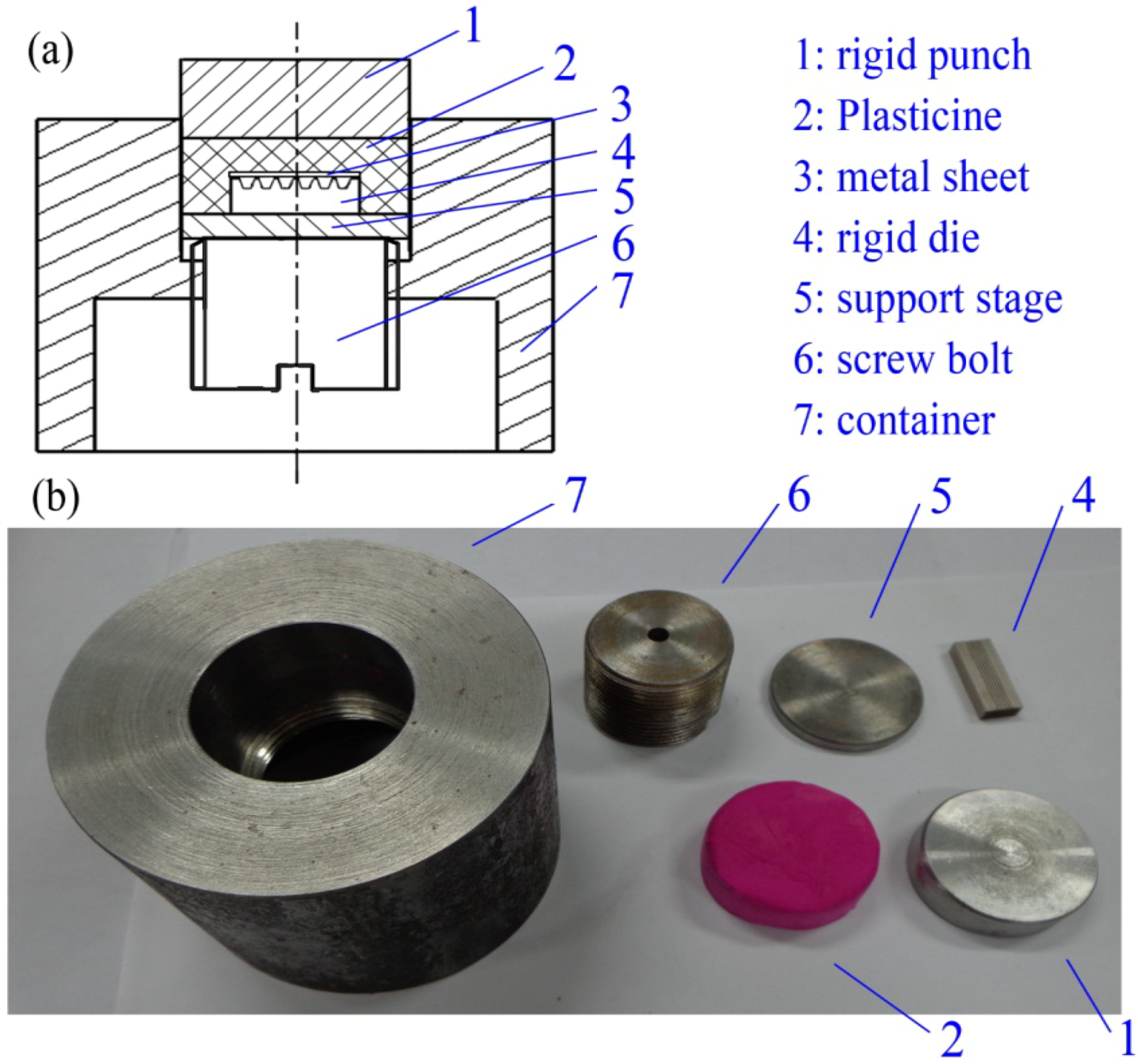
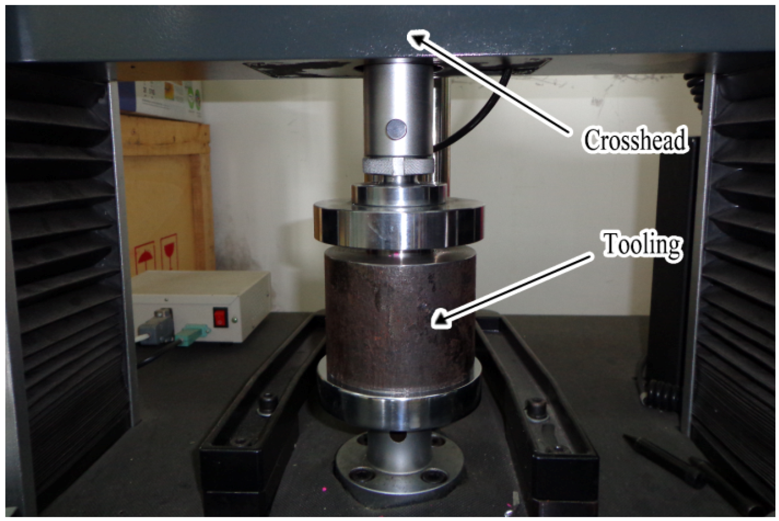
2. Experiment Setup


3. Experimental Results and Discussions


4. Numerical Simulation
4.1. Modeling Requirements
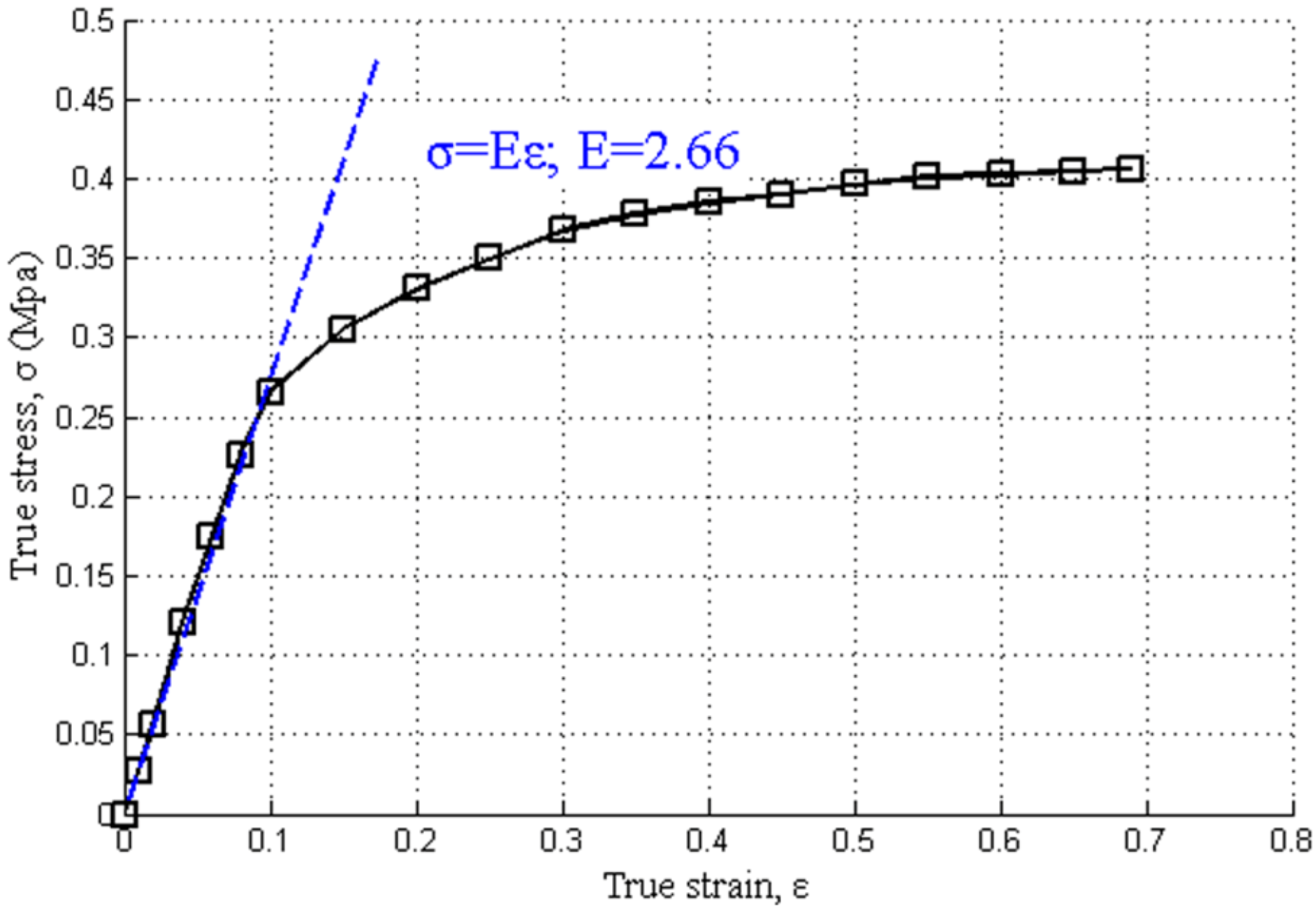
4.1.1. Metal Sheet Material Constitutive Model
4.1.2. Elastic-Linear Strain Hardening Material Model for Plasticine

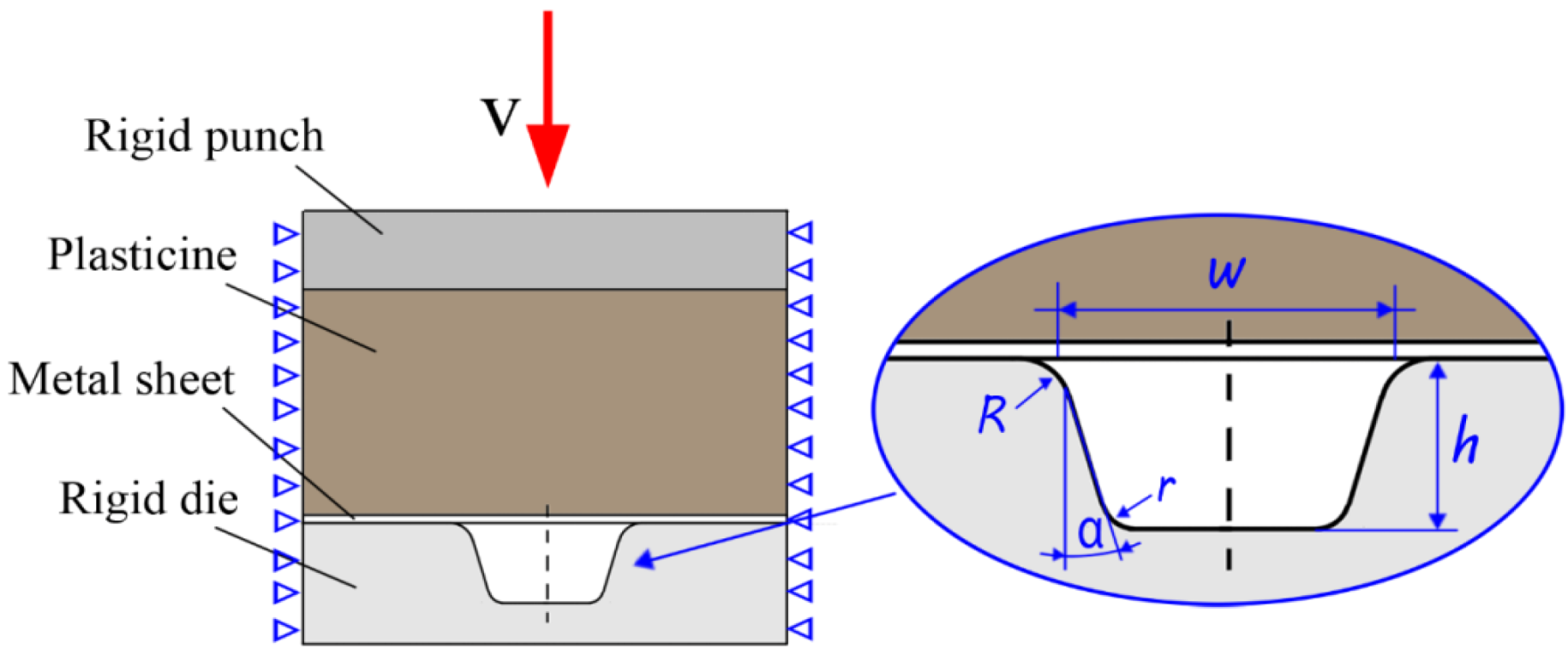
4.2. Finite Element Model
- Micro draw angle: α = 10°;
- Upper radius of the rigid die: R = 40 μm;
- Lower radius of the rigid die: r = 20 μm;
- Width of the micro groove: w = 320 μm;
- Depth of the micro groove: h = 500 μm.

4.3. Simulation Results and Discussions


5. Conclusions
- (1)
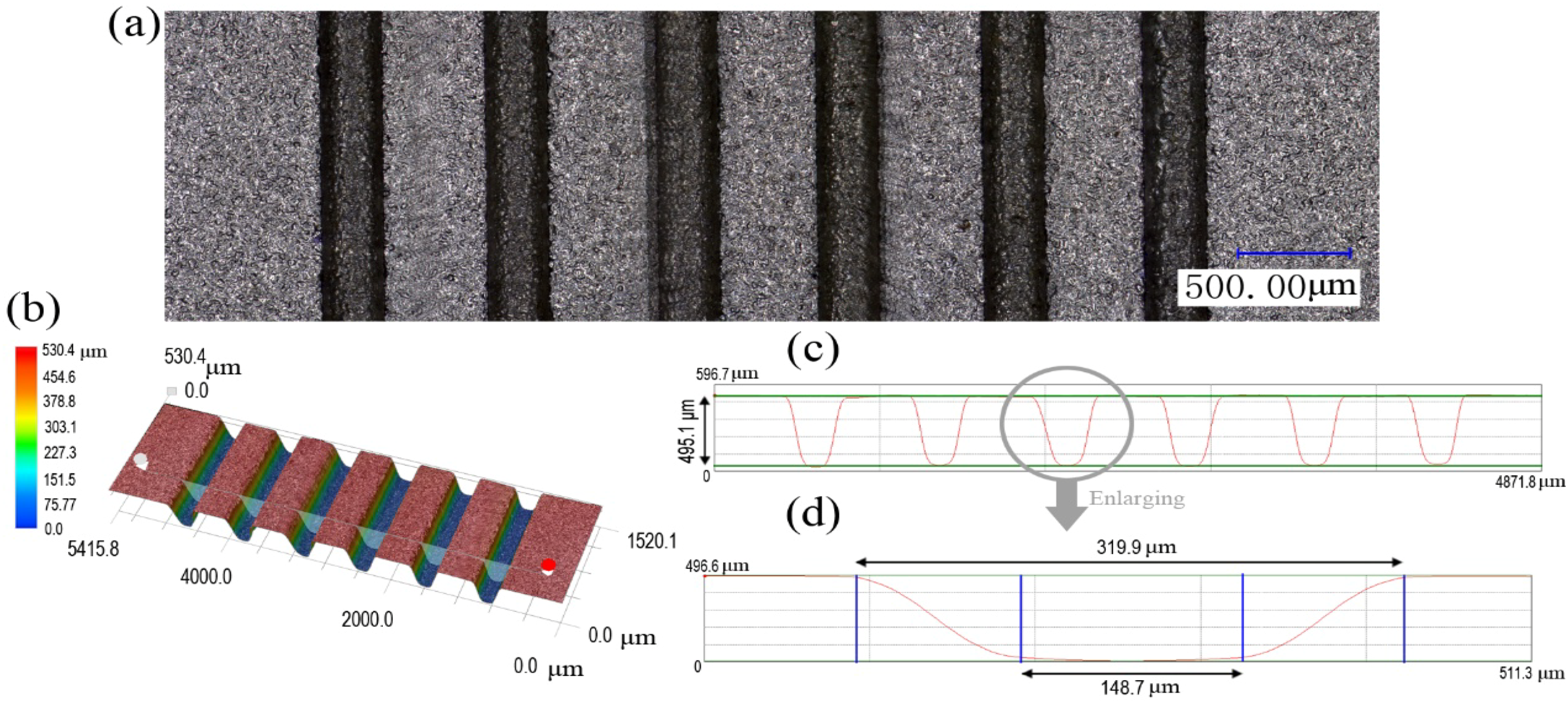
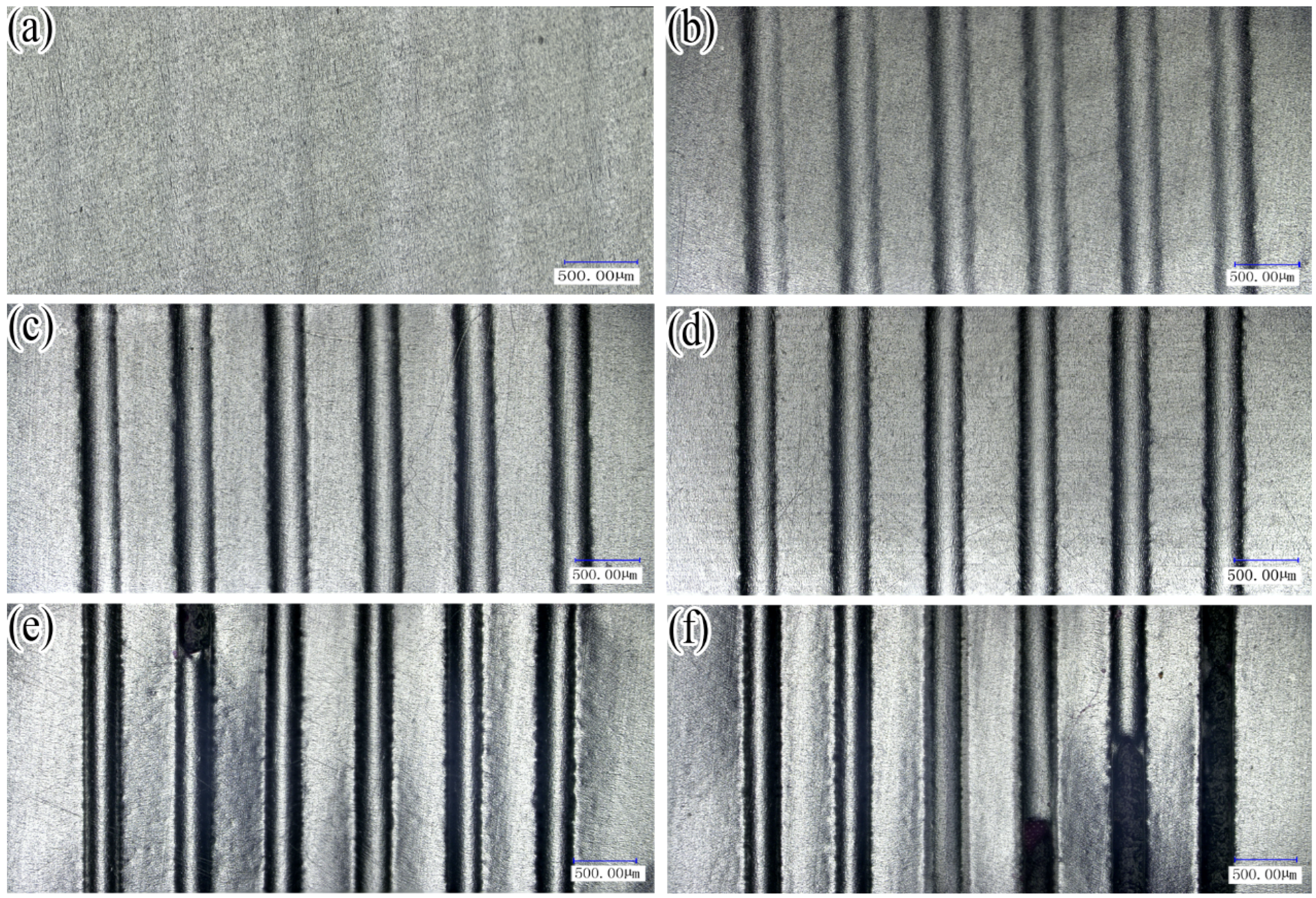
- By experiment, the whole six array micro-channels can be obtained. It was observed that the surfaces of the micro-channels possess good surface quality. Since the plasticine for the soft punch is softer than the metal sheets and other rigid dies, the stamping process can be considered as a non-damage forming process.
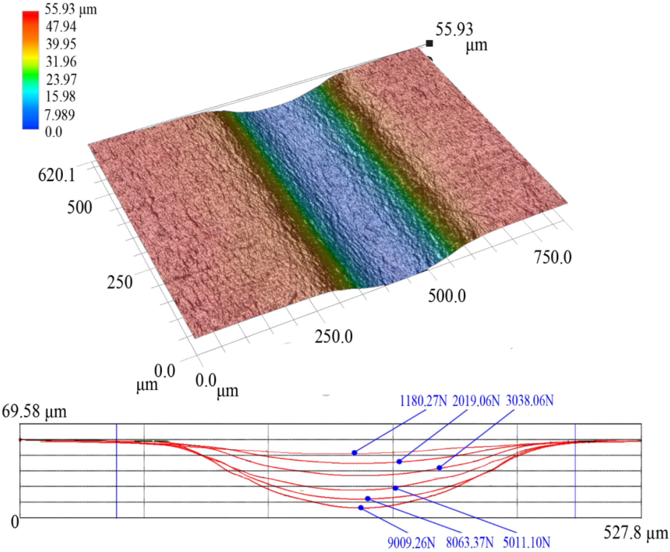
- (2)
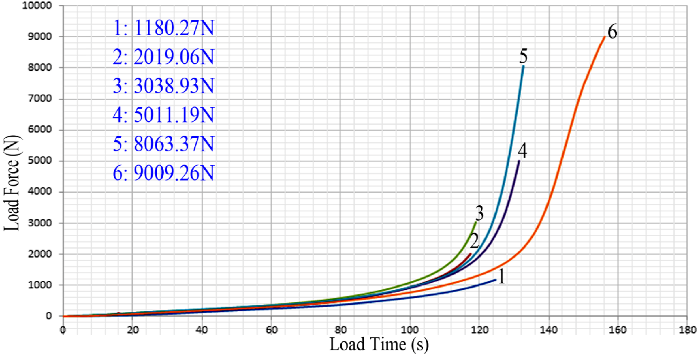
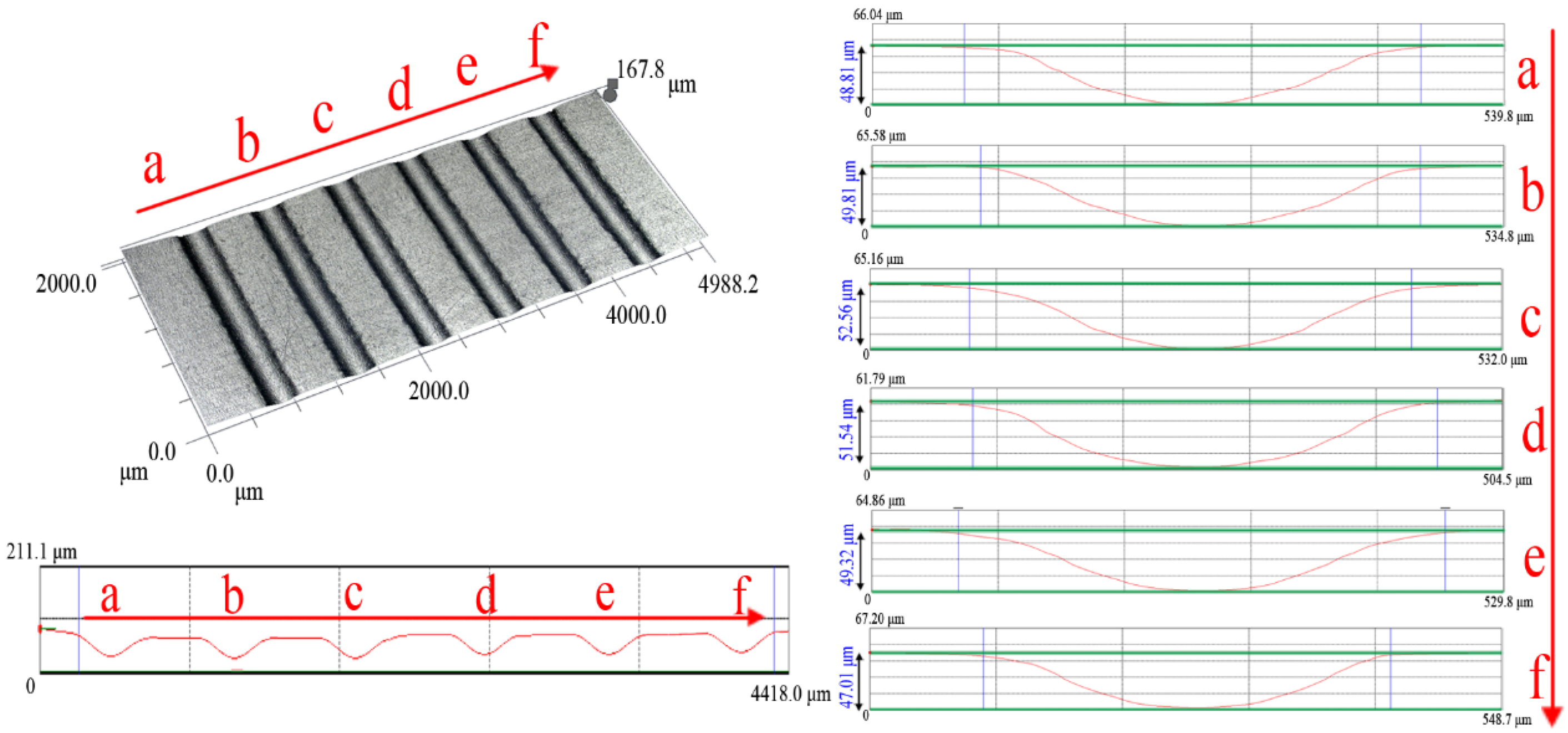
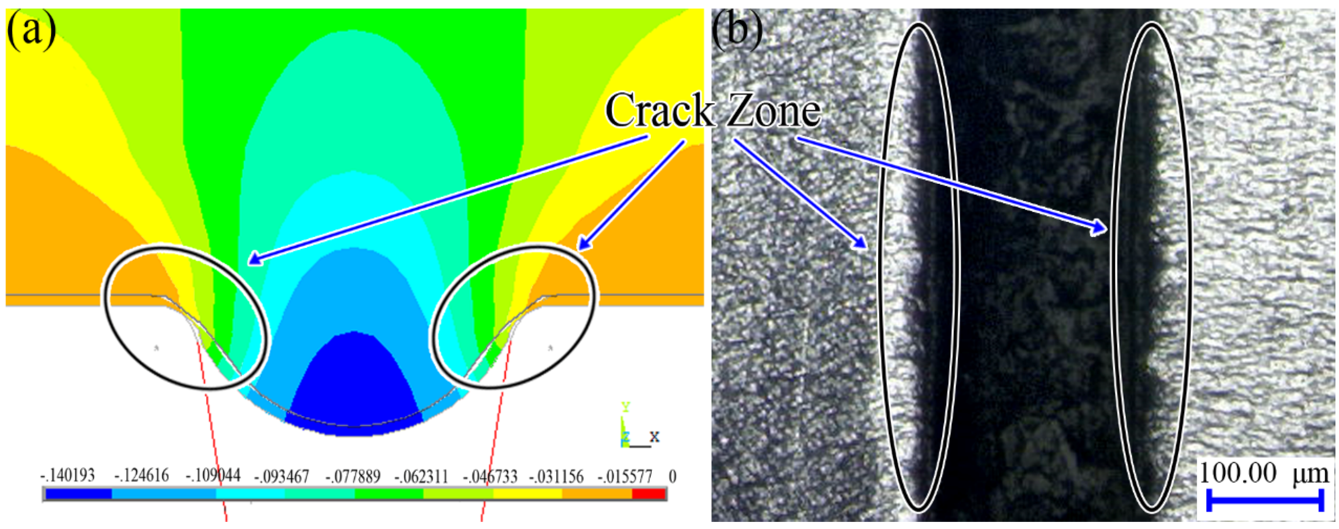
- The depths of the channels are increased with increase in the final load forces. When the final load force reaches a certain level, cracks can be observed. Additionally, according to the distribution of the array micro-channels as well as the depth changes, it can be assumed that the existence of friction between the container wall and the plasticine is responsible for the uneven distribution of the array micro-channel depths.
- (3)
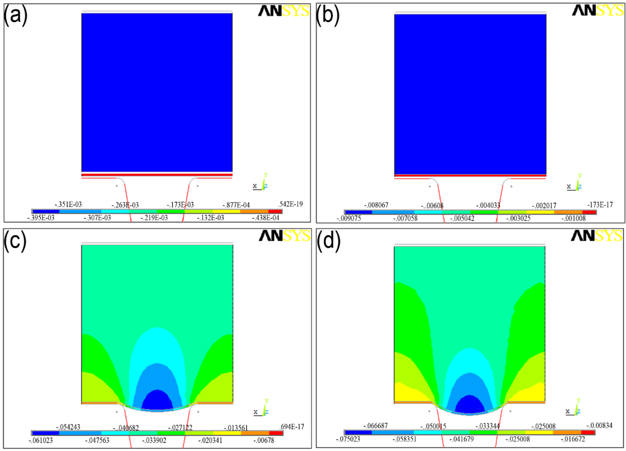
- According to the simulation results, the micro sheet stamping process may be divided into two different stages: the first is the plasticine self-deformation stage; the second is the metal sheets’ deformation under the pressure of plasticine to move downward with filling of the metal sheets until they reach the form limit.
- (4)
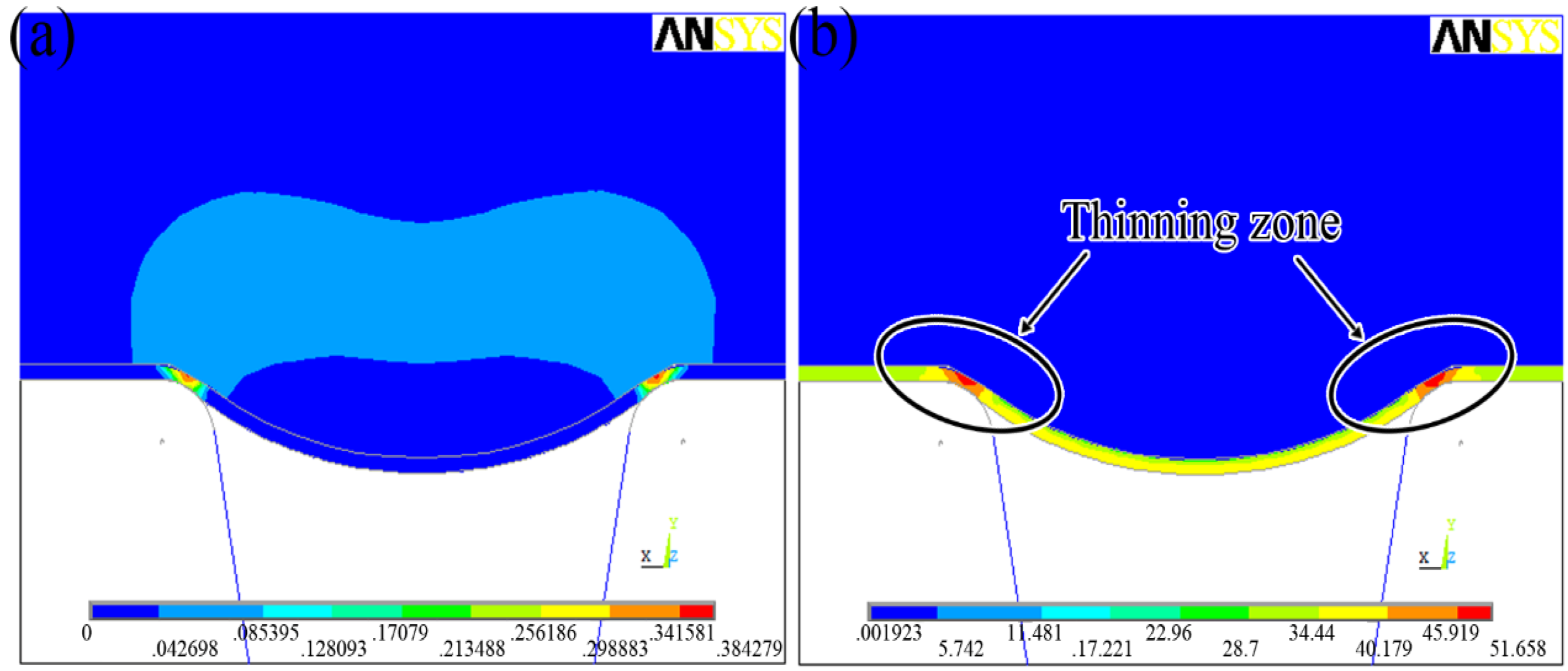
- Based on the contour of von Mises stress distribution, the maximum von Mises stress of the work piece occurred in the corner region of the work piece. During the process, the outside material of the sheet is bent, and then drawn into the die cavity. The inner material is pushed downwards and the tension force is applied at the corner region. The interfacial friction resists the material flow and further accelerates the material thinning. The thin zone of the sheet is located in the corner region which is the same as the maximum von Mises stress zone. It is easy to generate a crack and have the risk of sheet cracks.
Acknowledgments
Author Contributions
Conflicts of Interest
References
- Chan, W.; Fu, M. Experimental and simulation based study on micro-scaled sheet metal deformation behavior in microembossing process. Mater. Sci. Eng. A 2012, 556, 60–67. [Google Scholar]
- Raulea, L.V.; Goijaerts, A.M.; Govaert, L.E.; Baaijens, F.P.T. Size effects in the processing of thin metal sheets. J. Mater. Process. Technol. 2001, 115, 44–48. [Google Scholar] [CrossRef]
- Michel, J.-F.; Picart, P. Size effects on the constitutive behaviour for brass in sheet metal forming. J. Mater. Process. Technol. 2003, 141, 439–446. [Google Scholar] [CrossRef]
- Jaisingh, A.; Narasimhan, K.; Date, P.P.; Maiti, S.K.; Singh, U.P. Sensitivity analysis of a deep drawing process for miniaturized products. J. Mater. Process. Technol. 2004, 147, 321–327. [Google Scholar] [CrossRef]
- Vollertsen, F.; Hu, Z.; Niehoff, H.S.; Theiler, C. State of the art in micro forming and investigations into micro deep drawing. J. Mater. Process. Technol. 2004, 151, 70–79. [Google Scholar] [CrossRef]
- Peng, L.; Liu, F.; Ni, J.; Lai, X. Size effects in thin sheet metal forming and its elastic-plastic constitutive model. Mater. Des. 2007, 28, 1731–1736. [Google Scholar] [CrossRef]
- Peng, L.; Hu, P.; Lai, X.; Mei, D.; Ni, J. Investigation of micro/meso sheet soft punch stamping process—Simulation and experiments. Mater. Des. 2009, 30, 783–790. [Google Scholar] [CrossRef]
- Browne, D.J.; Battikha, E. Optimisation of aluminium sheet forming using a flexible die. J. Mater. Process. Technol. 1995, 55, 218–223. [Google Scholar] [CrossRef]
- Sala, G. A numerical and experimental approach to optimise sheet stamping technologies: Part II—Aluminium alloys rubber-forming. Mater. Des. 2001, 22, 299–315. [Google Scholar] [CrossRef]
- Thiruvarudchelvan, S. The potential role of flexible tools in metal forming. J. Mater. Process. Technol. 2002, 122, 293–300. [Google Scholar] [CrossRef]
- Dirikolu, A.H.; Akdemir, E. Computer aided modelling of flexible forming process. J. Mater. Process. Technol. 2004, 148, 376–381. [Google Scholar] [CrossRef]
- Shuqin, X.; Yuan, F. FEM analysis and experimental research on complex forming. J. Mater. Process. Technol. 1997, 69, 208–211. [Google Scholar] [CrossRef]
- Sofuoglu, H.; Rasty, J. Flow behavior of Plasticine used in physical modeling of metal forming processes. Tribol. Int. 2000, 33, 523–529. [Google Scholar] [CrossRef]
- Sofuoglu, H.; Gedikli, H. Physical and numerical analysis of three dimensional extrusion process. Comput. Mater. Sci. 2004, 31, 113–124. [Google Scholar] [CrossRef]
- Sofuoglu, H. A technical note on the role of process parameters in predicting flow behavior of plasticine using design of experiment. J. Mater. Process. Technol. 2006, 178, 148–153. [Google Scholar] [CrossRef]
- Niehoff, S.H.; Vollertsen, F. Laser induced shock waves in deformation processing. Metalurgija 2005, 11, 183–194. [Google Scholar]
- Sofuoglu, H.; Rasty, J. Three-dimensional analysis of extrusion process utilizing the physical modeling technique. J. Energy Resour. Technol. 1993, 115, 32–40. [Google Scholar] [CrossRef]
- Adams, M.; Aydin, I.; Briscoe, B.; Sinha, S. A finite element analysis of the squeeze flow of an elasto-viscoplastic paste material. J. Non-Newton. Fluid Mech. 1997, 71, 41–57. [Google Scholar] [CrossRef]
- Aydin, I.; Biglari, F.R.; Briscoe, B.J.; Lawrence, C.J.; Adams, M.J. Physical and numerical modelling of ram extrusion of paste materials: conical die entry case. Comput. Mater. Sci. 2000, 18, 141–155. [Google Scholar] [CrossRef]
© 2014 by the authors; licensee MDPI, Basel, Switzerland. This article is an open access article distributed under the terms and conditions of the Creative Commons Attribution license (http://creativecommons.org/licenses/by/3.0/).
Share and Cite
Wang, X.; Zhang, D.; Gu, C.; Shen, Z.; Liu, H. Research on the Micro Sheet Stamping Process Using Plasticine as Soft Punch. Materials 2014, 7, 4118-4131. https://doi.org/10.3390/ma7064118
Wang X, Zhang D, Gu C, Shen Z, Liu H. Research on the Micro Sheet Stamping Process Using Plasticine as Soft Punch. Materials. 2014; 7(6):4118-4131. https://doi.org/10.3390/ma7064118
Chicago/Turabian StyleWang, Xiao, Di Zhang, Chunxing Gu, Zongbao Shen, and Huixia Liu. 2014. "Research on the Micro Sheet Stamping Process Using Plasticine as Soft Punch" Materials 7, no. 6: 4118-4131. https://doi.org/10.3390/ma7064118