1. Introduction
Selective Laser Melting (SLM) is a process which belongs to Rapid Manufacturing (RM), which directly produces end-use products or parts. The RM is a direction of Rapid Prototyping (RP) technology, other than Rapid Tooling (RT). SLM represents an evolution of the Selective Laser Sintering (SLS) process that was developed and patented by Carl Deckard and Joe Beaman at the University of Texas at Austin in the mid-1980s for producing plastic prototypes [
1,
2]. The success of SLM, which is probably the most rapidly growing technique in RP and Layer manufacturing (LM) technologies, results mainly from the ability to create metal parts with complex shapes and intrinsic engineered features. Moreover, this technique is particularly interesting for the possibility of producing parts with mechanical properties better or at least comparable with those of components produced with traditional processes. This result can be demonstrated by several studies. Ng
et al. [
3] investigated the effects of laser processing parameters on the microstructure and mechanical properties of selective laser-melted magnesium finding that hardness values and elastic modulus of the laser melted magnesium were comparable with the cast magnesium ingot. Attar
et al. [
4] reported that SLM was able to produce high-strength CP-Ti parts superior to those of conventional processes. Prashanth
et al. [
5] built Al–12Si samples characterised by a maximum strength two times higher than the corresponding values of the cast material.
Most SLM literature concerns the optimization process parameters in order to obtain almost full density of parts and good mechanical properties of the bulk materials [
6,
7,
8,
9].
In recent years, SLM has been used to fabricate lattice structures for the production of lightweight components, because of the high geometrical freedom that can be realized in comparison to conventional manufacturing processes [
10,
11,
12,
13,
14].
The interest in manufacturing parts with tailored porosity is rapidly growing in scientific research. This aspect is also connected to the opportunity of employing innovative technologies based on additive techniques of Layer Manufacturing (LM). There are several applications of porous materials ranging from the biomedical to aerospace sectors, where they are used in heat transfer and acoustics as filters [
15,
16].
The potential of the SLM Ti6Al4V material as high performance parts in aerospace, automotive and medical applications is actively being explored by researchers and companies throughout the world. Studies on SLM Ti6Al4V micro-lattice structure as core material in sandwich construction showed that this material has significant potential that merits further examination and analysis [
17,
18].
Other researchers have shown the great potential of Ti6Al4V alloy in future aerospace applications [
19], or in the civil aircraft field [
20]. Further studies have shown the possibility of using this titanium alloy for biomedical applications [
21].
Particular attention is focused on the production of biomedical customised net-shape prostheses or devices from metallic powders. Implants are traditionally manufactured via investment casting, forging or machining, and formed by different components with bulk properties that are optimized for particular design criteria, such as bio-compatibility, strength, flexibility, wear resistance or bone ingrowth. These parts are bonded or mechanically attached together. One challenge to this traditional method is achieving sufficiently strong, permanent bonds between the implant sections that will not fail under the fatigue loading imposed by the body of the patient.
An approach to avoid joining mismatches is the use of monolithic metallic implants, but the latter solution is characterized by two types of issues: from a mechanical point of view these devices present dissimilar properties compared with bone ones, causing the stress shielding phenomenon with a consequent decay of osseous tissue and a reduction in the
in vivo duration of the implants; considering the biological aspect, the critical point is osteointegration, as traditional prostheses have to be further treated to obtain surfaces which facilitate the interaction of biological fluids and consequently strengthen the bond between tissue and implant, accelerating the healing process and the vascularisation. In order to solve the last issue, coatings with hydroxyapatite, PMMA (Polymethylmethacrylate) or surface treatments are usually employed, but these processes lengthen the production cycle [
22,
23].
SLM represents an alternative to traditional processes [
24,
25,
26]; the advantage of such technology is connected with the possibility of manufacturing complex geometries directly from a three-dimensional CAD model, obtaining parts with tailored, interconnected porosity and surface features which allow biological processes and bone ingrowth. A further positive aspect is represented by the reduction of production time compared to traditional techniques. Indeed, data obtained from CT scans are used to design an optimal fit prosthesis via CAD/CAM. This model can be adopted to produce a customised implant through layer fabrication.
In order to create a metallic implant with mechanical properties similar to bone ones, a tailored porosity in the component is necessary. The presence of cavities reduces stiffness mismatch and, as a consequence, stress shielding [
27]. A porous part can be produced via LM in two different ways: The first approach considers the bulk model and creates internal pores with powder partial fusion through the adequate choice of process parameters [
27,
28]; the latter uses a model with cavities and characterized by periodic cellular unit [
24,
29,
30,
31]. A third approach combines both above-quoted methods [
32].
The first method does not allow reaching porosity greater than a certain percentage, since the connection among the powder particles is not feasible with too low values of specific energy [
33]. Furthermore, a critical aspect is the removal of loose particles, which may cause human irritations in biomedical devices. The second approach presents minor restrictions.
In this paper, the feasibility of manufacturing lattice structures with tailored porosity adopting SLM process and their properties was studied. A Ti6Al4V powder, biocompatible and corrosion resistant, is used employing an EOSINT M270 titanium version laser sintering system with optimized exposure parameters to obtain full density of laser sintered parts. The lattice structure considered in the experimental phase is a pillar textile one, comprised of four vertical strut columns and four couples of struts inclined at ±45° with respect to cell axes of symmetry. A previous work on this structure was performed by Contuzzi
et al. [
15] processing via SLM the 18 Ni Marage 300 steel. They demonstrated that using vertical reinforcements loading capability of the base structure could be significantly improved.
Different topology structures were studied considering three parameters: the size cell (L); the truss size (t); and the number of reinforcements (R). In order to reduce the number of experiments a Taguchi experimental plane was used. The performance of these structures were analysed in terms of dimensional accuracy, roughness, micro-hardness, mechanical strength under compression and energy absorbed per unit mass.
2. Results and Discussion
2.1. Visual Inspections
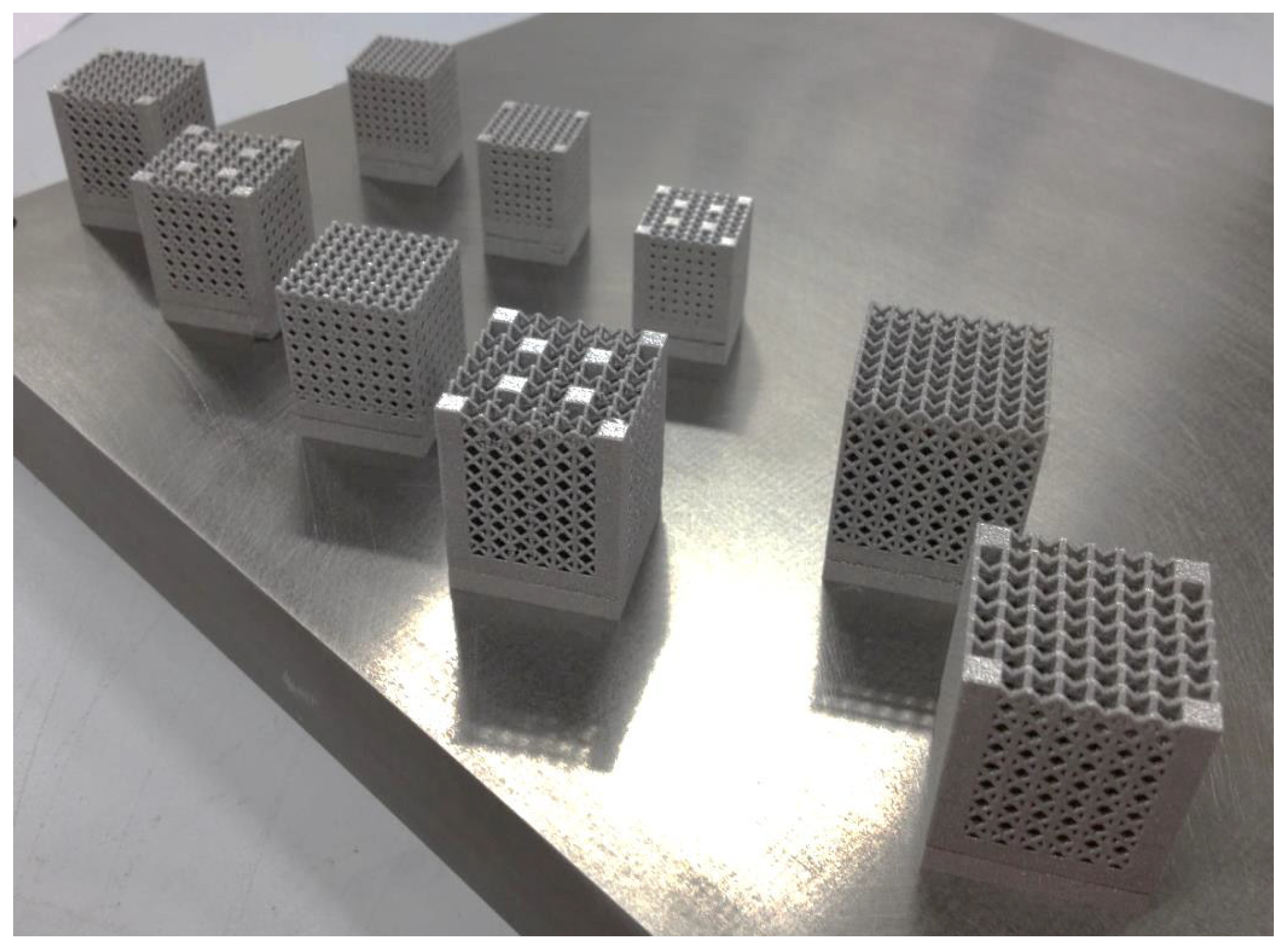
Figure 1 shows the samples on the building platform. Before the part removal from the platform, a heat treatment was carried out at 650 °C for 2 h in argon atmosphere in order to avoid oxidation. The aim of this procedure is to operate a relief of stresses due to high thermal gradients experienced during the manufacturing process. Then, specimens were sandblasted to remove partially molten particles.
Figure 1.
Samples on the building platform.
Figure 1.
Samples on the building platform.
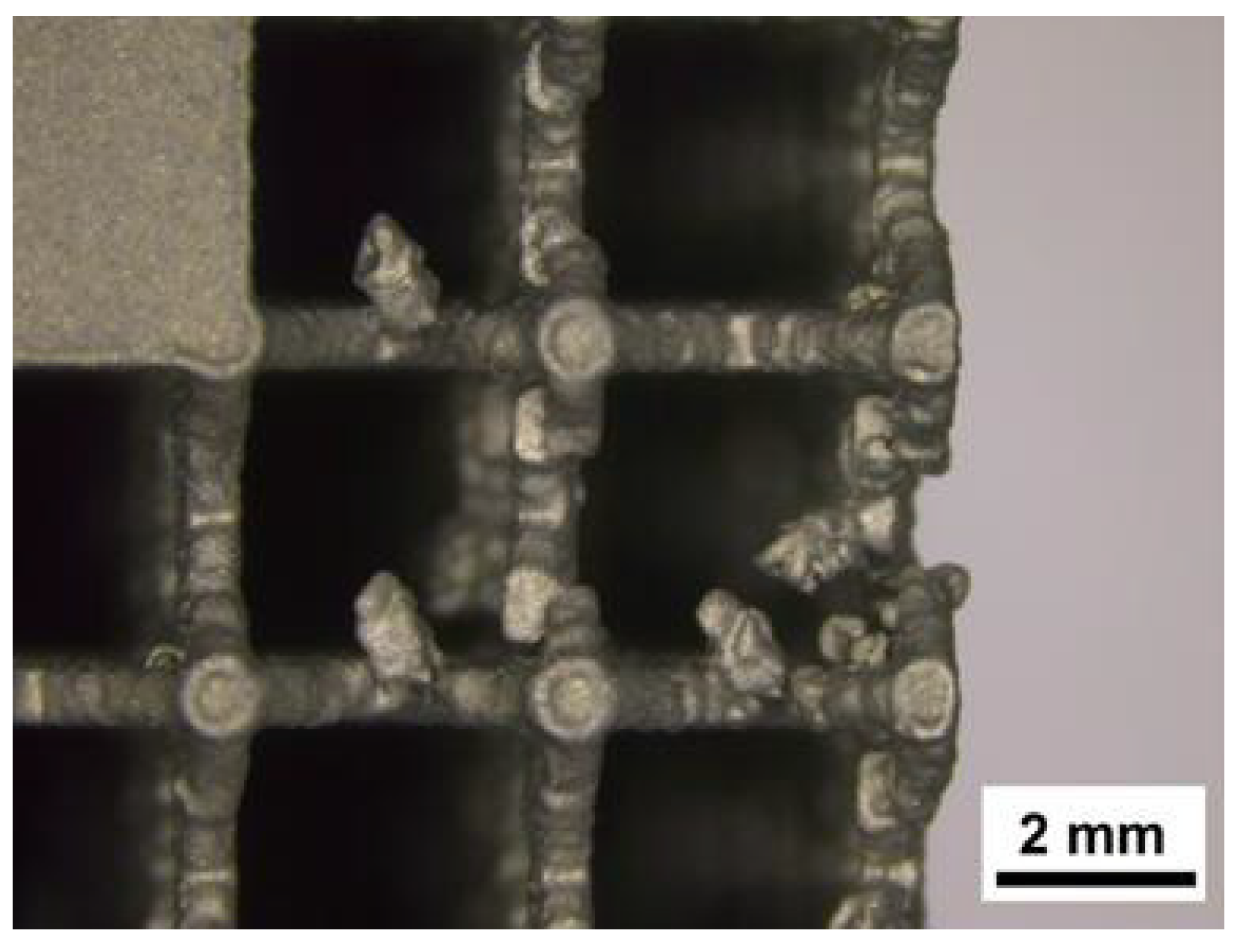
The only non-stochastic configuration which created issues during the fabrication is corresponding to sample 7. Observing the defects, it is noticed that some trusses have been bent in the recoating phase. This phenomenon is connected both with truss and cell size; indeed, the coupling of minimum thickness of the truss with the maximum cell size resulted in the instability of laser sintered part (
Figure 2). The other samples were not characterized by any imperfections proving the capability of the SLM technique.
Figure 2.
Defects observed in test 7.
Figure 2.
Defects observed in test 7.
2.2. Dimensional Analysis of Lattice Structures and Cell Features
A CMM was employed to perform metrological analysis and verify accuracy of the manufacturing process. In particular, lattice structure sizes were measured and their average values were reported in
Table 1, where
aeff is the measure of the effective side of the structure; and Δ the error in µm. The sample height was not considered since it is affected more by the finishing operations than the building capabilities of SLM. It can be inferred that deviations from model dimensions are quite small; even considering each measurement, the gap is less than 50 µm.
Table 1.
Results of the metrological analysis.
Table 1.
Results of the metrological analysis.
| Test | a (mm) | aeff (mm) | Δ (µm) |
|---|
| 1 | 16.5 | 16.477 | −23 |
| 2 | 16.6 | 16.578 | −22 |
| 3 | 16.7 | 16.663 | −37 |
| 4 | 20.5 | 20.531 | 30 |
| 5 | 20.6 | 20.590 | −10 |
| 6 | 20.7 | 20.681 | −19 |
| 7 | 24.5 | 24.491 | −9 |
| 8 | 24.6 | 24.614 | 14 |
| 9 | 24.7 | 24.705 | 5 |
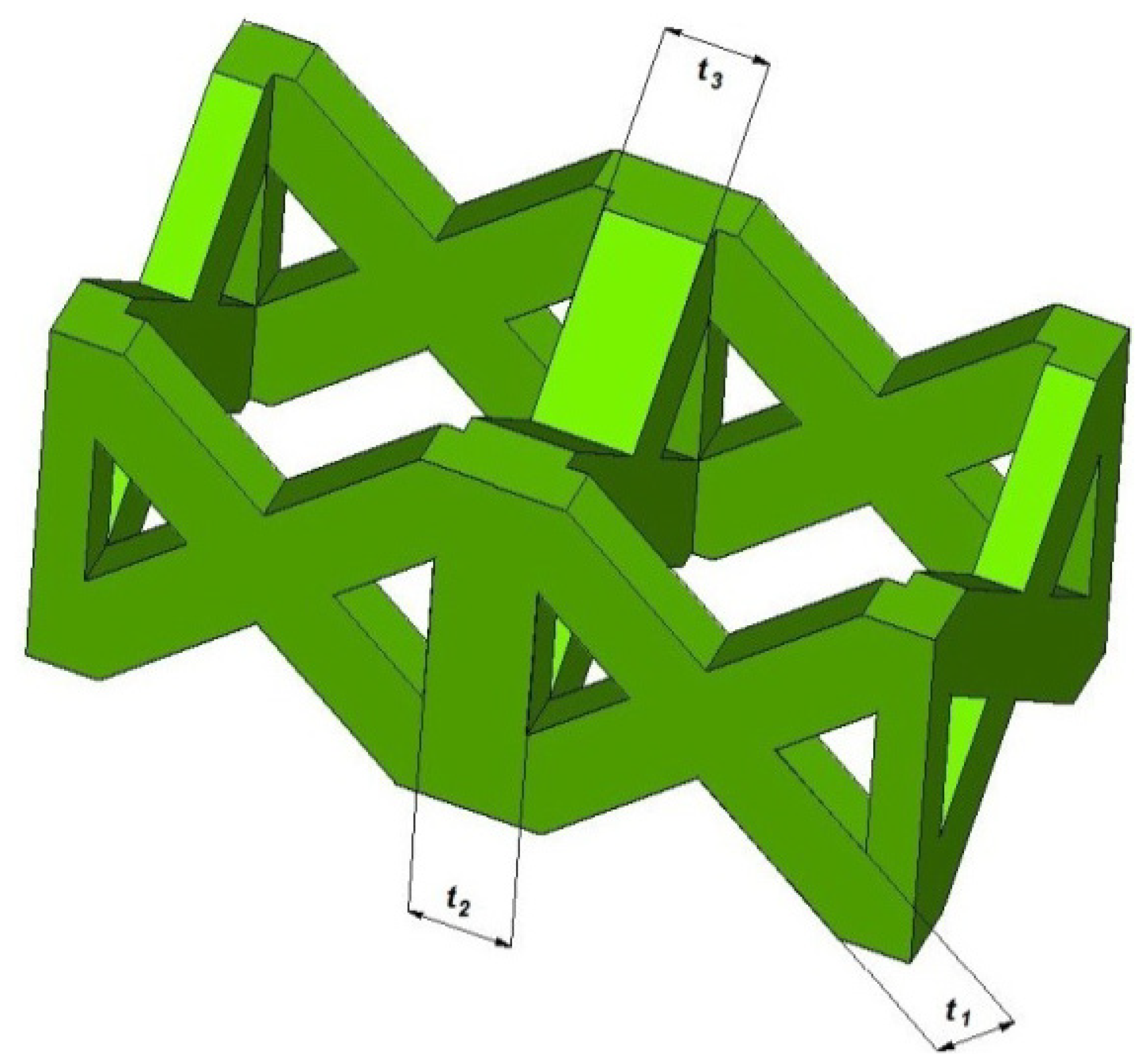
The layer fabrication of the process leads to a certain dimensional variation at the level of the single cell. In particular, trusses shown in
Figure 3 should present all the same thickness.
Table 2 reports the average values observed for trusses through the macrographs acquired via a Leica S8AP0 stereomicroscope (Leica, Solms, Germany) and elaborated with Leica Application Suite software. A deviation from the theoretical dimensions is highlighted, in conjunction with a discrepancy between trusses with variable orientation.
Figure 3.
Truss thickness measured via stereomicroscope.
Figure 3.
Truss thickness measured via stereomicroscope.
This anomaly also affects the effective relative density (ρreff) of the lattice structures in comparison with designed porosity (ρr). ρr is evaluated as the ratio between volume of CAD model (Vt) and volume of full element (Vb); whereas, effective volume of the lattice structure (Veff) is calculated through cell feature measurements.
Table 2.
Results of stereomicroscope analysis and evaluation of effective relative density.
Table 2.
Results of stereomicroscope analysis and evaluation of effective relative density.
| Test | t (μm) | t1 (μm) | t2 (μm) | t3 (μm) | Vb (mm3) | Vt (mm3) | ρr | Veff (mm3) | ρreff |
|---|
| 1 | 500 | 515 | 523 | 508 | 4356 | 1389 | 0.3190 | 1441 | 0.3308 |
| 2 | 600 | 626 | 609 | 621 | 4409 | 2026 | 0.4596 | 2102 | 0.4768 |
| 3 | 700 | 725 | 716 | 703 | 4462 | 2598 | 0.5822 | 2635 | 0.5905 |
| 4 | 500 | 513 | 506 | 507 | 8405 | 2354 | 0.2800 | 2401 | 0.2857 |
| 5 | 600 | 614 | 610 | 608 | 8487 | 3414 | 0.4022 | 3467 | 0.4085 |
| 6 | 700 | 708 | 708 | 700 | 8570 | 3239 | 0.3779 | 3265 | 0.3810 |
| 7 | 500 | 512 | 512 | 510 | 14406 | 4108 | 0.2852 | 4178 | 0.2900 |
| 8 | 600 | 615 | 604 | 604 | 14524 | 3245 | 0.2234 | 3319 | 0.2285 |
| 9 | 700 | 715 | 724 | 710 | 14642 | 4962 | 0.3388 | 5072 | 0.3464 |
The difference in terms of relative density, however, is quite limited and presents a maximum value of 1.7%. This value is acceptable when compared with the deviation obtained by Lin
et al. [
30], using the same process and powder, which reaches 7%. Moreover, differences in relative density even more marked, over 20%, have been observed in the experimentation of Parthasarathy
et al. [
24], who works with the same alloy but adopts the technique of EBM, demonstrating a less reliable reproduction of the CAD model.
2.3. Roughness, Micro-Hardness and Microstructure
Undesirable in other sectors, in medical implants a coarse surface is an advantage because it enhances bone-implant fixing and accelerates the healing process as roughness increases osteo-conductivity.
The bond between the implant and bone tissue is excellent for
Ra values ranging between 1 and 10 µm [
34]. After performing a preliminary test on specimen roughness, a cut-off of 2.5 mm was chosen according to ISO 4288–2000 standard [
35] to guarantee a good reliability in
Ra range for samples under examination.
Ra roughness for lattice structures ranges from 6 to 14 µm and it is a function of the sandblasting process. Indeed, since the sandblasting is manual, sides directly exposed to the sand jet present a low irregularity. As a consequence, carrying out a homogeneous treatment on every surface, adequate roughness of laser sintered parts may be obtained.
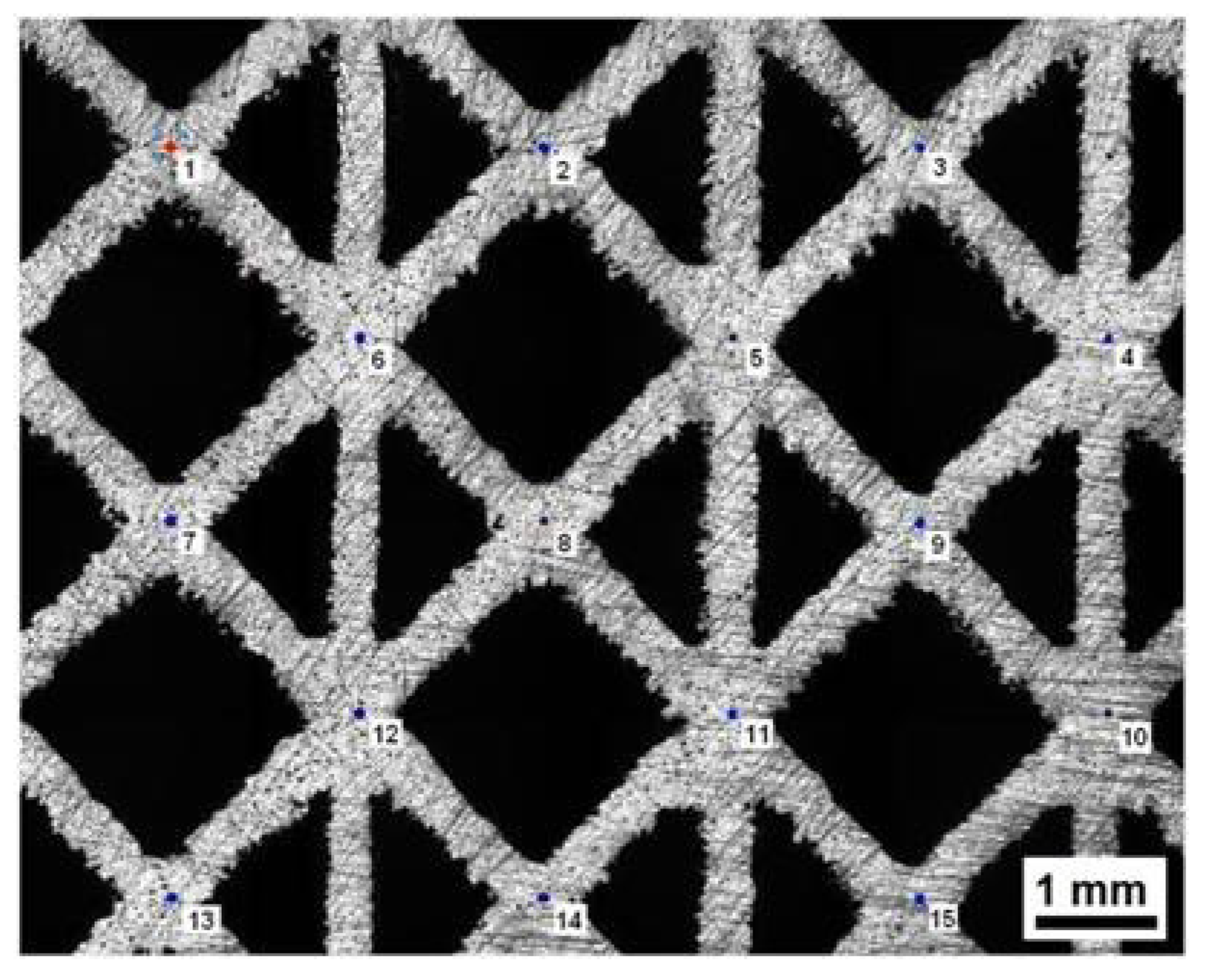
Micro-hardness tests were performed on grinded surfaces of different samples. As an example, results are shown for specimen in condition 4 (
Table 3). The indentations follow the path pointed out in
Figure 4. Micro-hardness is 398 ± 11 HV
0.3, which is greater than the minimum value of titanium alloys for medical use (349 HV) [
36].
The microstructure of the specimens recalls the typical one obtained for a sample in Ti6Al4V quenched from a temperature above the beta transus (about 995 °C). The behaviour during solidification is due to the fact that titanium alloys have different allotropic forms as a function of temperature. In particular, above the so-called beta transus temperature, the microstructure changes from alpha (hexagonal close packed) to beta (body centred cubic). Ti6Al4V is an alpha + beta alloy, because it contains Al which stabilizes the alpha phase, and V as a beta stabilizer. At room temperature equilibrium, this alloy supports a mixture of alpha and beta phases.
Table 3.
Results of micro-hardness for specimen in condition 4.
Table 3.
Results of micro-hardness for specimen in condition 4.
| Indentation | HV0.3 | d1 [µm] | d2 [µm] |
|---|
| 1 | 415 | 36.5 | 36.8 |
| 2 | 405 | 37.3 | 36.8 |
| 3 | 412 | 36.9 | 36.6 |
| 4 | 397 | 37.5 | 37.3 |
| 5 | 395 | 37.5 | 37.5 |
| 6 | 401 | 38.0 | 36.5 |
| 7 | 379 | 38.3 | 38.4 |
| 8 | 386 | 37.7 | 38.3 |
| 9 | 390 | 37.8 | 37.8 |
| 10 | 417 | 36.1 | 36.9 |
| 11 | 400 | 36.9 | 37.7 |
| 12 | 381 | 37.4 | 39.0 |
| 13 | 403 | 37.4 | 36.9 |
| 14 | 390 | 37.9 | 37.7 |
| 15 | 397 | 37.9 | 36.9 |
Figure 4.
Truss thickness measured via stereomicroscope.
Figure 4.
Truss thickness measured via stereomicroscope.
When a specimen is quenched from a temperature above the beta transus, martensitic alpha is obtained from beta grains. In alloys with low concentrations of beta-stabilizing elements, like Ti6Al4V, the martensite has a distorted hexagonal crystal lattice [
28]. Rapid solidification after the interaction with the laser beam leads to a greater hardness value compared to those ones of bulk base material, as showed by previous micro-hardness tests. Furthermore, no peculiar grain orientation was observed proving the SLM’s capability to produce parts with isotropic properties.
2.4. Compression Tests
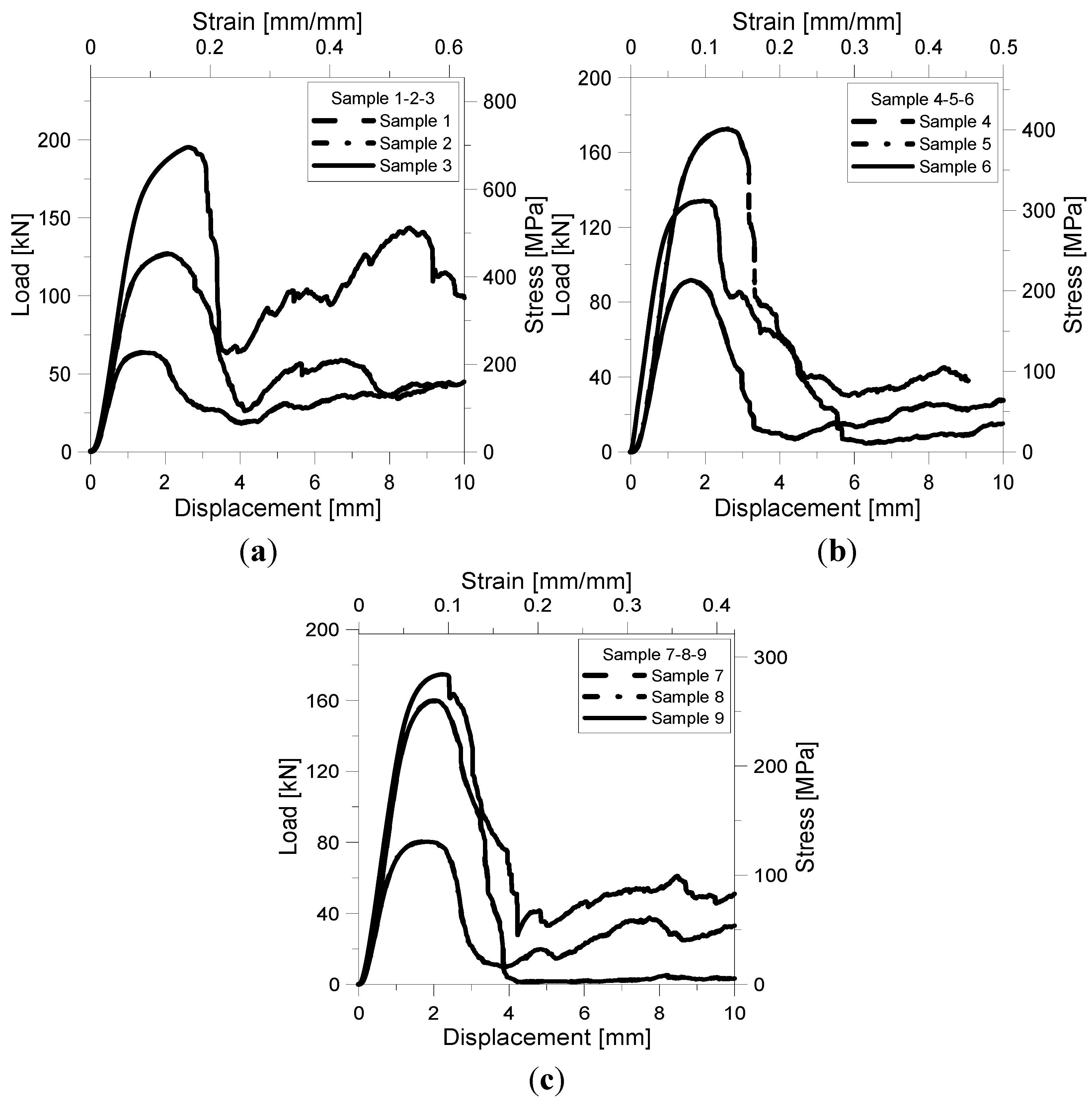
Figure 5a–c shows the load-displacement/stress-strain curves for cell size
L = 2, 2.5, 3 mm samples. Stress was determined as the ratio between the applied load measured by the load cell and the nominal cross-section of the specimen; strain was evaluated as the ratio between the measured shortening and nominal height of the specimen. Values of stress and strain were derived from the load-displacement curves recorded experimentally. Samples exhibit similar compressive stress-strain behaviour. After an initial region of linear elasticity, a gradual yield occurs followed by a peak compressive strength (σ
pk). This strength corresponds at the maximum stress that the structure can support before collapse. Continued loading resulted in a plastic collapse until breaking and densification. The degree of softening seems to be more affected by cell size and size of strut edge than by number of reinforcements. For impact energy absorption applications, a stress
versus strain response with little or no softening after yield is desirable [
37,
38]. Samples without reinforcements (1, 6 and 8) exhibit this behaviour having the smaller softening after yield. On the other hand, samples 2, 3 and 9 are able to bear load again and, therefore, could still absorb energy under compressive loading.
Figure 5.
Load-displacement/stress strain curves for L = 2 mm sample (a); L = 2.5 mm sample (b); and L = 3 mm sample(c).
Figure 5.
Load-displacement/stress strain curves for L = 2 mm sample (a); L = 2.5 mm sample (b); and L = 3 mm sample(c).
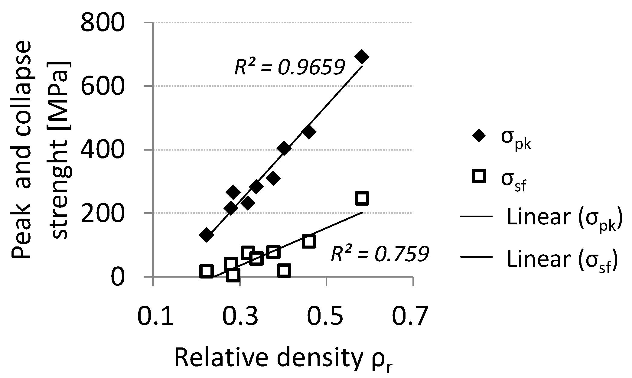
Values of peak and collapse strength (σ
sf) are listed in
Table 4. The collapse strength was calculated as the stress reached by the structure during the plastic collapse soon after the maximum strength. The maximum load carrying capability is achieved by sample 3 which is characterised by the smaller cell size, the highest size of strut edge and the highest relative density (ρ
r = 0.5822).
Table 4.
Values of peak and collapse strength for the samples.
Table 4.
Values of peak and collapse strength for the samples.
| Sample | σpk (MPa) | σsf (MPa) | ρr |
|---|
| 1 | 232.5 | 76 | 0.3190 |
| 2 | 456.6 | 111 | 0.4596 |
| 3 | 692.3 | 247 | 0.5822 |
| 4 | 215.8 | 40 | 0.2800 |
| 5 | 404.2 | 20 | 0.4022 |
| 6 | 309.8 | 78 | 0.3779 |
| 7 | 265.9 | 5.32 | 0.2852 |
| 8 | 131.6 | 18 | 0.2234 |
| 9 | 283.5 | 58 | 0.3388 |
Thus, the introduction of vertical reinforcements improves the load carrying capability of the lattice truss, as expected and as already demonstrated by Contuzzi
et al. [
15] with similar structures built by SLM using a maraging steel powder. Sample 3 also exhibits the lower degree of softening having the maximum collapse strength. Peak and collapse stress values increase almost linearly with relative density (
Figure 6): The correlation coefficient for the linear fitting is 0.965 for σ
pk and 0.759 for σ
sf.
Figure 6.
Peak and collapse compressive strength vs. relative density.
Figure 6.
Peak and collapse compressive strength vs. relative density.
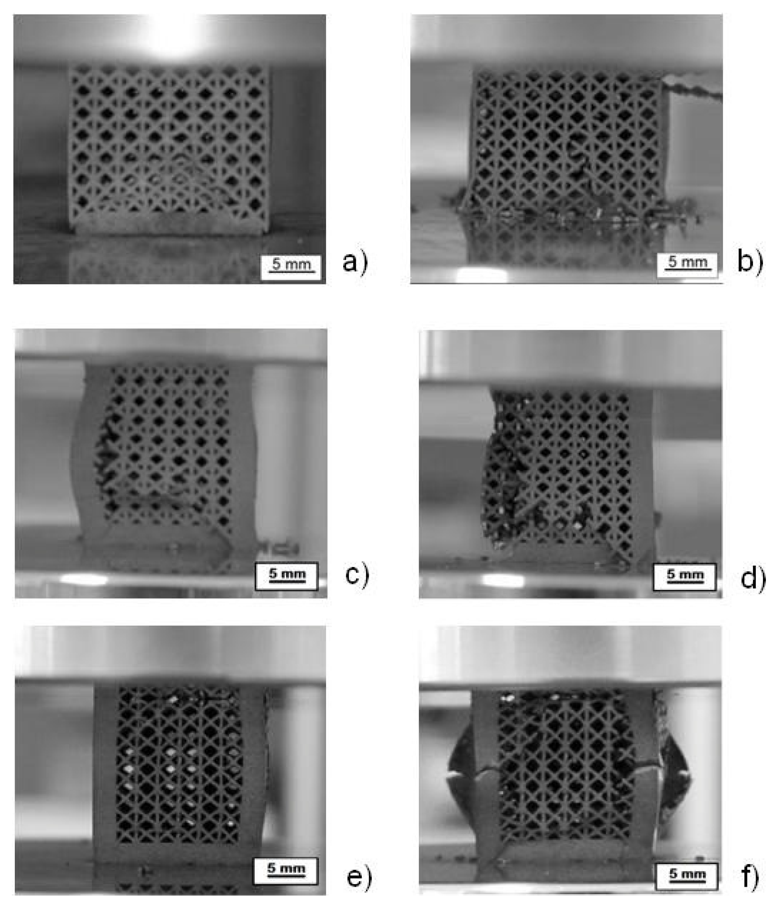
Figure 7 shows the collapse mode for samples 6, 9 and 7, which are representative of the three kinds of structures. Specifically,
Figure 7a,b illustrates the deformation of the base pillar textile lattice structure without reinforcements. Struts, after buckling, experience first a plastic collapse (a) and later on the rupture of structure (b). The structure with four reinforcements (c and d) breaks and collapses after buckling of vertical reinforcements. The structure with eight reinforcements (e and f) experiences first buckling and then breaking of the vertical reinforcements, followed by the collapse of the entire structure.
Figure 7.
Deformed structure without reinforcements (sample 6) (a,b); with four reinforcements (sample 9) (c,d); and with eight reinforcements (sample 7) (e,f).
Figure 7.
Deformed structure without reinforcements (sample 6) (a,b); with four reinforcements (sample 9) (c,d); and with eight reinforcements (sample 7) (e,f).
2.5. Statistical Analysis
In order to investigate the influence of the considered factors on the compressive behaviour of samples, the Analysis of Variance (ANOVA) was performed. The investigated factors are the cell size, the truss size and the number of vertical reinforcements. The analyzed output factors are: peak strength, collapse strength and the energy absorbed per unit mass.
The merits of different materials for impact energy absorption can be compared by determining the strain energy absorbed during their compression up to densification [
38]. The energy absorbed per unit volume
Wv, [
39] is defined by Equation (1):
In this case, the energy was calculated till a strain of 0.4 was reached. Energy absorbers of minimum mass are also important for weight sensitive applications. The energy absorbed per unit mass is defined by Equation (2):
where ρ is the density of the parent alloy.
The results of ANOVA are summarized in
Table 5,
Table 6 and
Table 7. The
p-value tells whether the effect for that term is significant. If the effect of a discrete factor is significant, then the variance of the factor is not zero. If a calculated p-value is greater than the level of significance, the effect of the parameter is judged not to be significant. The level of significance set to 0.07 allows selecting the parameters whose effect is not negligible from a statistical point of view [
40]. The ANOVA showed that only peak strength and energy absorbed per unit mass are affected by the three factors
L,
t and
R, while collapse strength is not influenced by the variation of these factors.
Table 5.
Analysis of variance for peak strength.
Table 5.
Analysis of variance for peak strength.
| Factors | Seq SS | Adj SS | Adj MS | F | p-Value |
|---|
| L | 84,056 | 84,056 | 42,028 | 28.08 | 0.034 |
| t | 54,451 | 54,451 | 27,226 | 18.19 | 0.052 |
| R | 79,861 | 79,861 | 39,931 | 26.68 | 0.036 |
Table 6.
Analysis of variance for collapse strength.
Table 6.
Analysis of variance for collapse strength.
| Factors | Seq SS | Adj SS | Adj MS | F | p-Value |
|---|
| L | 23,912 | 23,912 | 11,956 | 5.87 | 0.146 |
| t | 13,778 | 13,778 | 6,889 | 3.38 | 0.228 |
| R | 1,716 | 1,716 | 858 | 0.42 | 0.704 |
Table 7.
Analysis of variance for energy absorbed per unit mass.
Table 7.
Analysis of variance for energy absorbed per unit mass.
| Factors | Seq SS | Adj SS | Adj MS | F | p-Value |
|---|
| L | 0.089387 | 0.089387 | 0.044694 | 111.30 | 0.009 |
| t | 0.041269 | 0.041269 | 0.020635 | 51.39 | 0.019 |
| R | 0.011188 | 0.011188 | 0.005594 | 13.93 | 0.067 |
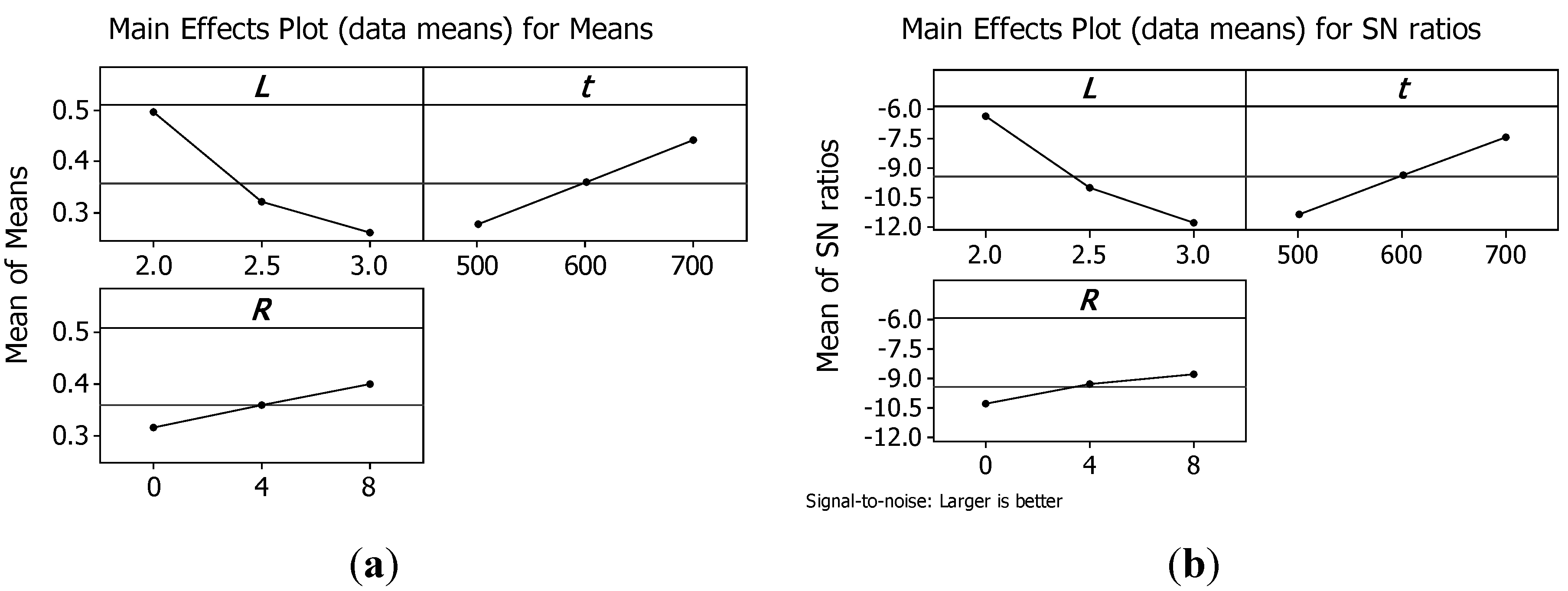
An optimization procedure was performed by means of the method of Taguchi. A loss function was defined which measured the deviation of the quality characteristic from a desired value. In order to assess the influence of each input factor on the output, the means and Signal-to-Noise ratios (S/N), for each control factor, were calculated. The signals are indicators of the effect on the average responses and the noises are measures of the influence on the deviations from the average responses, which accounts for the sensitiveness of the experiment output to noise factors. The appropriate S/N ratio must be chosen using previous knowledge, expertise, and understanding of the process. There are three categories of the quality characteristic in the analysis of the S/N ratio, i.e., the lower-the-better, the larger-the-better, and the nominal-the-better. In this study, the goals are to identify the factors which maximize peak strength and the energy absorbed per unit mass Wm and which are robust to noises.
Therefore, in this study, the S/N ratio was chosen according to the criterion the-larger-the-better. The S/N ratio for each level of process parameters is computed based on the S/N analysis. Regardless of the category of the quality characteristic, a larger S/N ratio corresponds to a better quality characteristic. Therefore, the optimal level of the process parameters is the level with the highest S/N ratio.
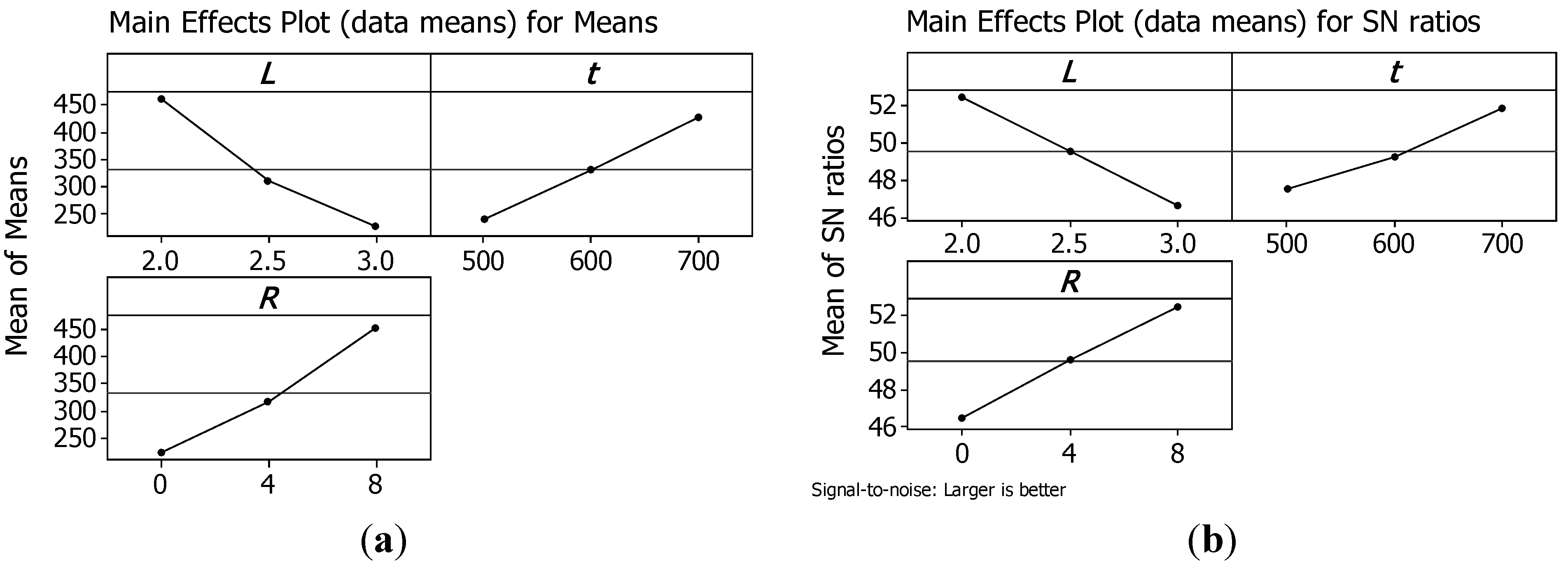
Figure 8 and
Figure 9 show the main effect plots for means and for S/N ratios, respectively, for peak strength and for the energy absorbed per unit mass
Wm.
Figure 8.
Main effects plot for means (a) and for S/N ratios (b) for peak strength.
Figure 8.
Main effects plot for means (a) and for S/N ratios (b) for peak strength.
Figure 9.
Main effects plot for means (a) and for S/N ratios (b) for energy absorbed per unit mass Wm.
Figure 9.
Main effects plot for means (a) and for S/N ratios (b) for energy absorbed per unit mass Wm.
Analysing plots, it is evident that both σpk and Wm can be maximised using structures with the minimum cell size L; the maximum truss size t; and the maximum number or reinforcements R.
Thus, the structure that presents the maximum load capability has also the maximum energy absorbed per unit mass till a strain of 0.4. Hence, the best configuration is reached by sample 3 that has a relative density of 0.5822.
3. Experimental Section
Referring to the choice of geometry, manufacturing technology has two main constraints. The former is connected with the minimum track which the laser beam is able to produce. The threshold value is 200 μm equal to the size of melted zone with a single spot. The latter concerns the lowest angle between the truss and building platform. In literature, some works showed that it is not recommended to use angles less than 45°, in order to not compromise laser sintered part stability [
15,
41,
42]. Indeed, with small angles, the overlap between each layer is minimal and this may cause their removal during the recoating phase. Moreover, previous works demonstrated that the pillar textile concept is one of the best structures in terms of low relative density and large compressive strength [
15].
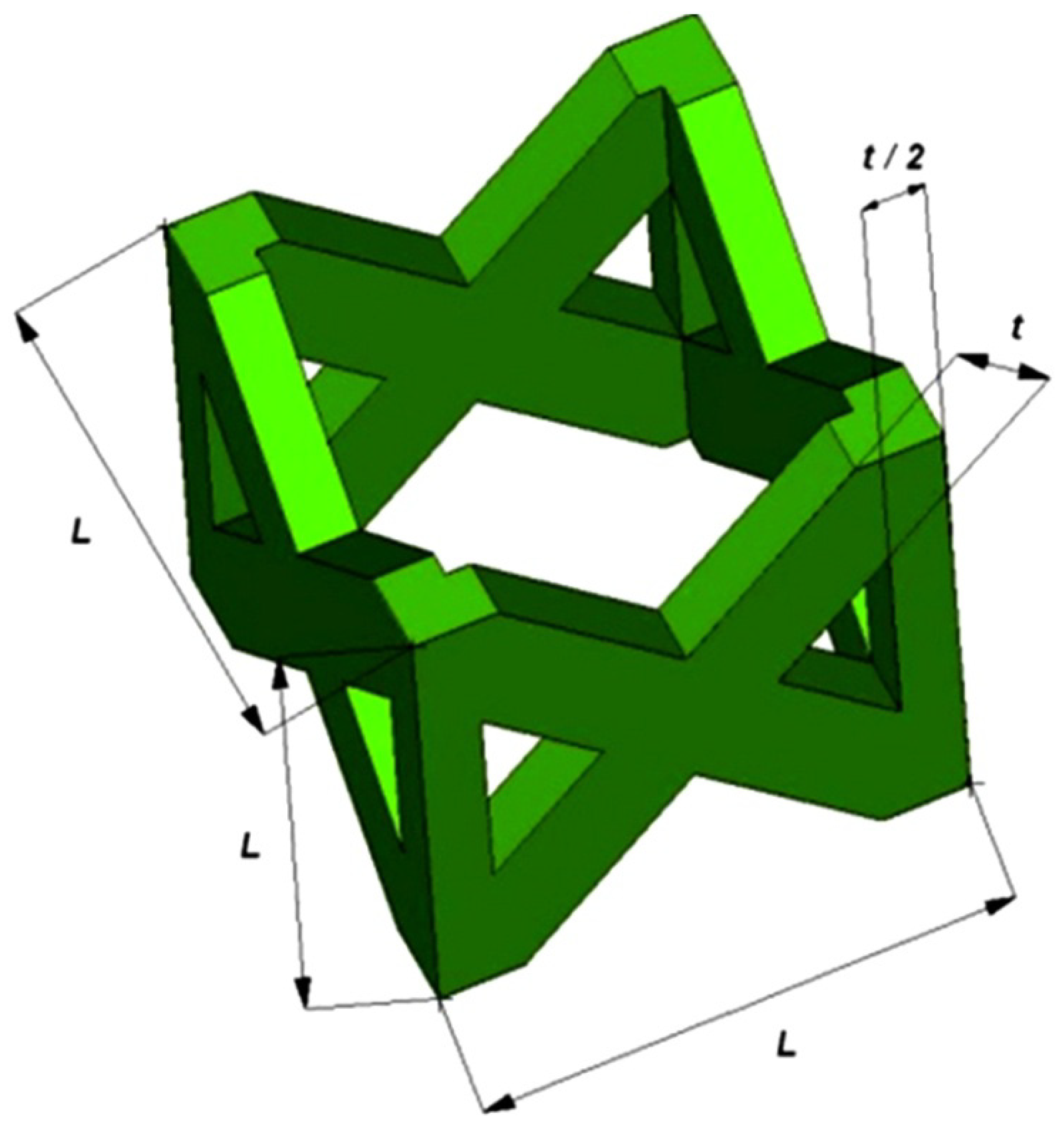
The pillar textile lattice structure, comprised of four vertical strut columns and four pairs of struts inclined at ±45° with respect to cell axes of symmetry, has been selected.
Figure 10 shows the unit cell of the lattice structure chosen in this study.
L is the length of the base side of the unit cell (
i.e., the cell size) and
t is the thickness of the single strut edge.
Figure 10.
Schematic illustration of the pillar textile unit cell and main geometric dimensions.
Figure 10.
Schematic illustration of the pillar textile unit cell and main geometric dimensions.
In order to test the suitability of SLM process in the examined context, an experimental campaign was planned to compare the behaviour of the above structures with variable cell (
L) and truss size (
t). Furthermore, vertical bars (
R) to reinforce the pillar lattice structures and improve stiffness were considered in some topologies. To minimize the number of experiments, Taguchi’s experiment planning was used. The experimental set-up was according to the L9 orthogonal array, as illustrated in
Table 8, where
a is the side and
h the height of complete lattice structures with a square section. Three factors were considered as input variables of the structures:
L,
t and
R. The three factors were changed on three different levels.
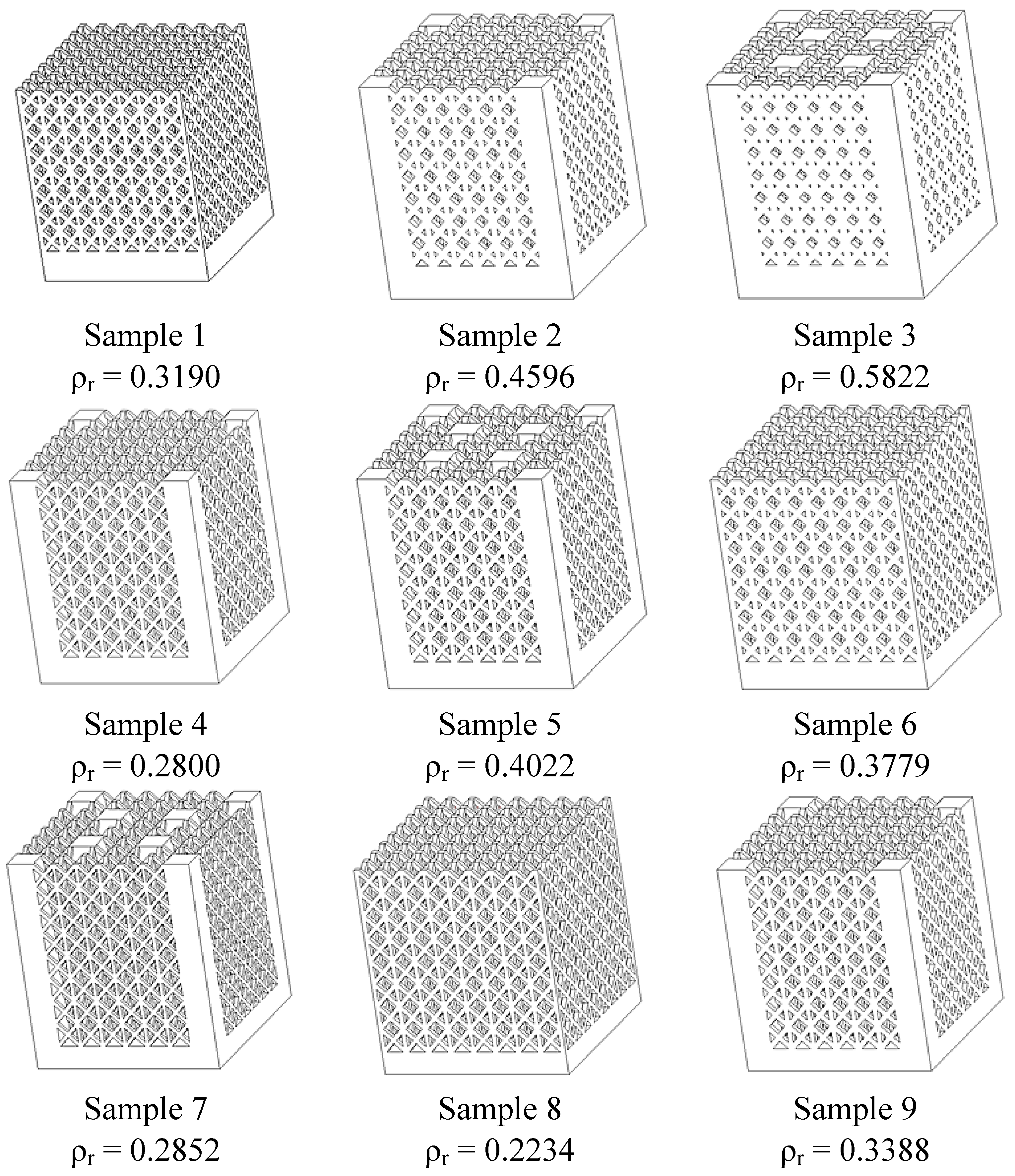
Figure 11 shows the nine combinations of samples, which have relative density (ρ
r) ranging between 0.2234 and 0.5822.
Table 8.
Fractional plan used for the experimental phase.
Table 8.
Fractional plan used for the experimental phase.
| Test | L (mm) | t (µm) | R | a (mm) | h (mm) | ρr |
|---|
| 1 | 2.0 | 500 | 0 | 16.5 | 19.0 | 0.3190 |
| 2 | 2.0 | 600 | 4 | 16.6 | 19.0 | 0.4596 |
| 3 | 2.0 | 700 | 8 | 16.7 | 19.0 | 0.5822 |
| 4 | 2.5 | 500 | 4 | 20.5 | 23.0 | 0.2800 |
| 5 | 2.5 | 600 | 8 | 20.6 | 23.0 | 0.4022 |
| 6 | 2.5 | 700 | 0 | 20.7 | 23.0 | 0.3779 |
| 7 | 3.0 | 500 | 8 | 24.5 | 27.0 | 0.2852 |
| 8 | 3.0 | 600 | 0 | 24.6 | 27.0 | 0.2234 |
| 9 | 3.0 | 700 | 4 | 24.7 | 27.0 | 0.3388 |
Figure 11.
Cell topologies of the nine combinations of parameters.
Figure 11.
Cell topologies of the nine combinations of parameters.
Lattice structures were manufactured using an EOSINT M270 titanium version system. Machine specifications are given in
Table 9. Ti6Al4V powder with a mean particle size of 30 µm was used in this investigation and alloy chemical composition is listed in
Table 10. The powder quality is important to reduce the content of impurities (oxygen, hydrogen and nitrogen), which might negatively affect mechanical properties of laser sintered parts with phenomena like embrittlement. Furthermore, the composition fulfils the requirements of ASTM F1472 [
43] regarding maximum concentration of impurities in titanium alloy for surgical implant applications. During the processing phase, the CAD model is sliced into thin layers whose thickness is 30 µm. Within the laser sintering machine, the chamber is filled with argon in order to operate in a controlled atmosphere with percentages of oxygen lower than 0.13% (to prevent oxidation during sintering and explosions because of fumes and vapours). The titanium powder from the dispenser is moved by the recoater and layered on a building platform, where the laser beam selectively melts powder bed following the scan path. After that, the dispenser is lifted up to supply material for a new layer and the process platform is lowered by the thickness of one layer. This cycle is repeated until the parts are completed.
Table 9.
EOSINT M270 titanium version specifications.
Table 9.
EOSINT M270 titanium version specifications.
| Effective Building Volume | 250 × 250 × 215 mm3 |
|---|
| Building speed | 2 ÷ 20 mm3/s |
| Layer thickness | 20 ÷ 100 μm |
| Laser type | Yb–fibre |
| Maximum power | 200 W |
| Precisions optics | F-theta lens, high speed scanner |
| Focused spot diameter | 0.090 mm |
Table 10.
Chemical composition of Ti6Al4V (wt%), * Max.
Table 10.
Chemical composition of Ti6Al4V (wt%), * Max.
| Al | V | O | N | C | H | Fe | Ti |
|---|
| 5.5 ÷ 6.75 | 3.5 ÷ 4.5 | 0.2 * | 0.05 * | 0.08 * | 0.015 * | 0.30 * | Bal. |
The exposure parameters for manufacturing the samples in Ti6Al4V were chosen in order to obtain full density of parts by SLM, exploiting past experience on the same alloy, and are summed up in
Table 11 [
28]. These parameters affect energy density, which is a key factor in SLM. Indeed, too high values of energy per volume lead to an excessive melting of the layers with a substantial shrinkage and a consequent balling. This phenomenon occurs when the molten material does not wet the underlying substrate due to the surface tension, which tends to spheroidise the liquid. On the other hand, too low values of energy density are not suitable to ensure adhesion between consecutive layers, because the penetration depth is not adequate [
33]. The SLM process is the same as SLS except for the much higher laser energy density required. The amount of energy density causes the powder to fully melt in SLM and to partial melt in SLS. In SLM, nearly full density parts can be produced without the need for post-processing steps [
44,
45].
Table 11.
Exposure parameters adopted for manufacturing the samples.
Table 11.
Exposure parameters adopted for manufacturing the samples.
| Factor | Symbol | Value |
|---|
| Laser power | P | 170 W |
| Scan speed | v | 1.25 m/s |
| Hatch spacing | hs | 0.10 mm |
| Scan length | l | 5 mm |
| Layer thickness | s | 30 µm |
To perform the characterization of the specimens, dimensional measurements were carried out both for single cell and whole structure. The attention was focused on accuracy as past studies pointed out that additive techniques do not allow the faithful replication of the model with significant changes in terms of porosity content and mechanical behaviour [
29,
30]. The whole samples were examined using a coordinate measuring machine (CMM) DEA Global Image Clima (Hexagon Metrology, Stockholm, Sweden), with a maximum permissible μm error of 1.5 +
M/333, where
M is measured in millimetres. In order to perform analysis for cell features, macrographs were acquired via a Leica S8AP0 stereomicroscope and elaborated with Leica Application Suite software.
A further analysis concerns the roughness of laser sintered components since this factor has a high impact on osteointegration and therefore on interactions of implant surfaces with biological fluids [
39,
46]. Roughness measurements were carried out through a Taylor-Hobson Form Talysurf 50 (Taylor-Hobson, Leicester, England).
Moreover, micro-hardness tests were performed on samples to make a comparison with hardness of Ti6Al4V alloy adopted in the medical field. In the experimental campaign, Vickers micro-hardness was tested according to EN ISO 6507-1 [
47] using a ZwickRoell ZHVµ-A instrument (ZwickRoell, Ulm, Germany); a load of 2.94 N (
i.e., 0.3 kgf) was used for 10.5 s at 60 µm/s speed.
The nine cell variants considered in this study were all tested under uniaxial compression. As underlined by Harrysson
et al., this kind of test is really important for hip stems and, in general, for highly-stressed prostheses [
25]. Mechanical tests were performed under displacement control with an Instron 4467 machine equipped with a 200 kN load cell; end-shortening was supplied to the specimen by setting compression speed to 0.5 mm/min.
4. Conclusions
In this paper, the feasibility of manufacturing lattice structures with tailored porosity adopting SLM process and their properties has been studied. A Ti6Al4V powder, biocompatible and corrosion resistant, was used employing an EOSINT M270 titanium version laser sintering system with optimized exposure parameters to obtain the full density of laser sintered parts.
The lattice structure considered in the experimental phase is a pillar textile one, comprised of four vertical strut columns and four pairs of struts inclined at ±45° with respect to the cell axes of symmetry. A campaign was planned to compare the behaviour of the above structures with variable cells, truss sizes and vertical bars as reinforcements. To minimize the number of experiments, Taguchi’s experiment planning was used.
The only non-stochastic configuration which created issues during the fabrication is corresponding to lattice structure with minimum thickness of the truss and maximum cell size. The other samples were not characterized by imperfections proving the capability of the SLM technique.
The results of metrological analysis with a CMM demonstrate the great accuracy of the manufacturing process with a gap in model dimensions less than 50 µm. The layer fabrication of the process leads a certain dimensional variation at the level of the single cell, which also affects the effective relative density of the lattice structures in comparison with designed porosity. The difference in terms of relative density, however, is quite limited and acceptable when compared with the deviation obtained in other experimentations, using a similar process and powder.
From the results of the roughness test, it is inferred that adequate roughness of laser sintered parts may be obtained with sandblasting to enhance bone-implant fixing and accelerate the healing process. Regarding micro-hardness tests, the average value is greater than the minimum one of titanium alloys for medical use (349 HV). Indeed, the high energy density of laser beams causes the formation of martensitic alpha, a microstructure which is characterised by great resistance.
Compression tests were performed in order to evaluate the mechanical behaviour under compression of the micro-lattice topology variants. It is found that the load carrying capability of the structure is affected by the number of vertical reinforcements, by strut edge size and cell size. Peak and collapse stress values increase almost linearly with relative density. The maximum load carrying capability and the lower degree softening is achieved by sample 3 which is characterised by the smaller cell size, the highest size of strut edge and the highest relative density. This result is also demonstrated by statistical optimisation performed by the method of Taguchi. This analysis has shown that the structure that presents the maximum load capability has also the maximum energy absorbed per unit mass.

 ,
, 


