
Wire Arc Additive Manufacturing of AZ31 Magnesium Alloy: Grain Refinement by Adjusting Pulse Frequency

Abstract
:1. Introduction
2. Experimental Procedures
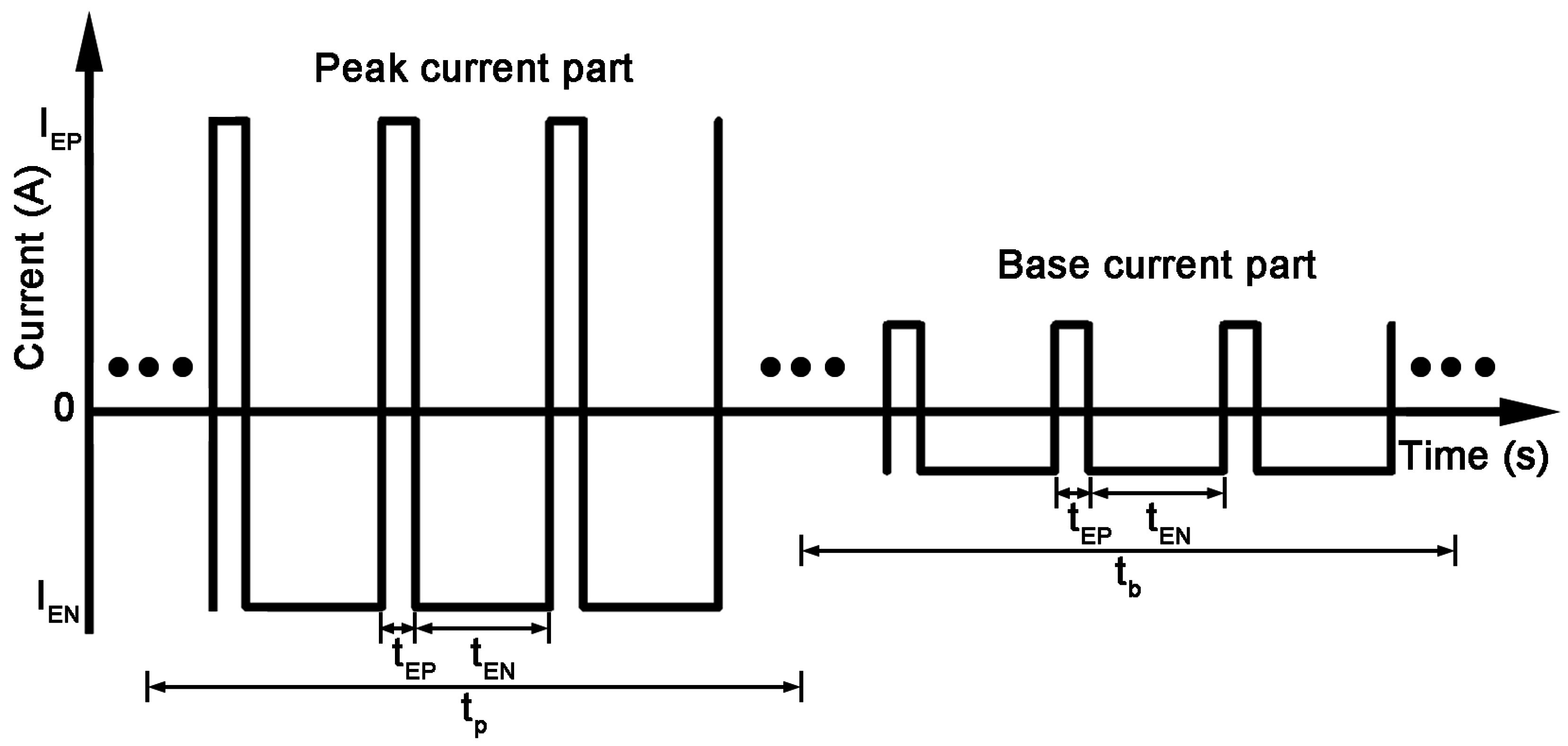
2.1. Experimental Setup and Manufacturing Process
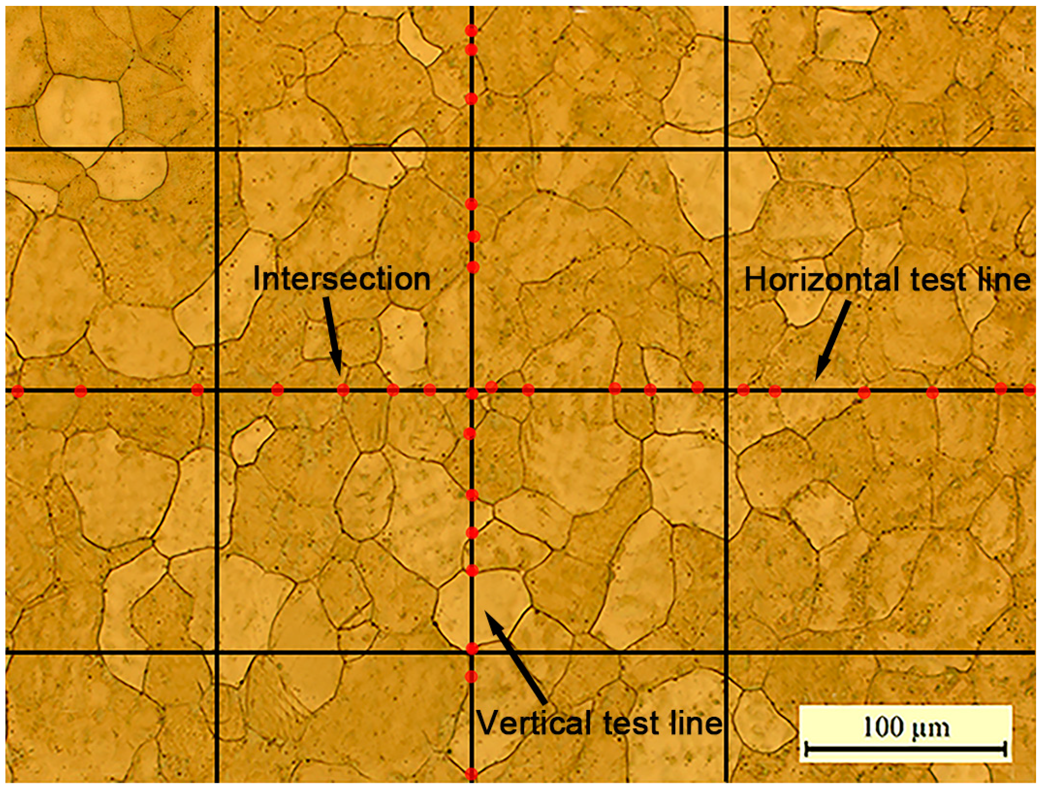
2.2. Research Methodology
3. Results and Discussion
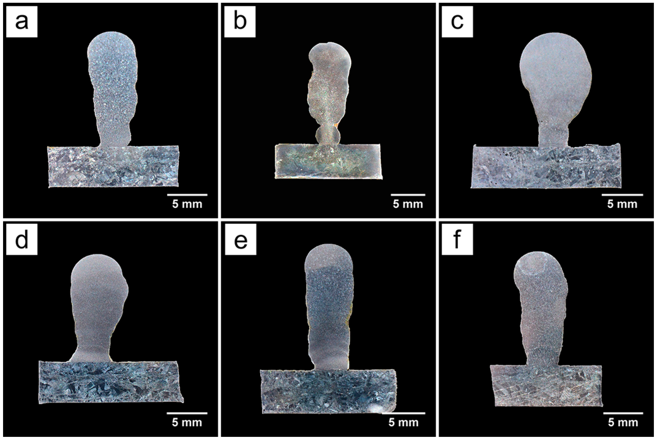
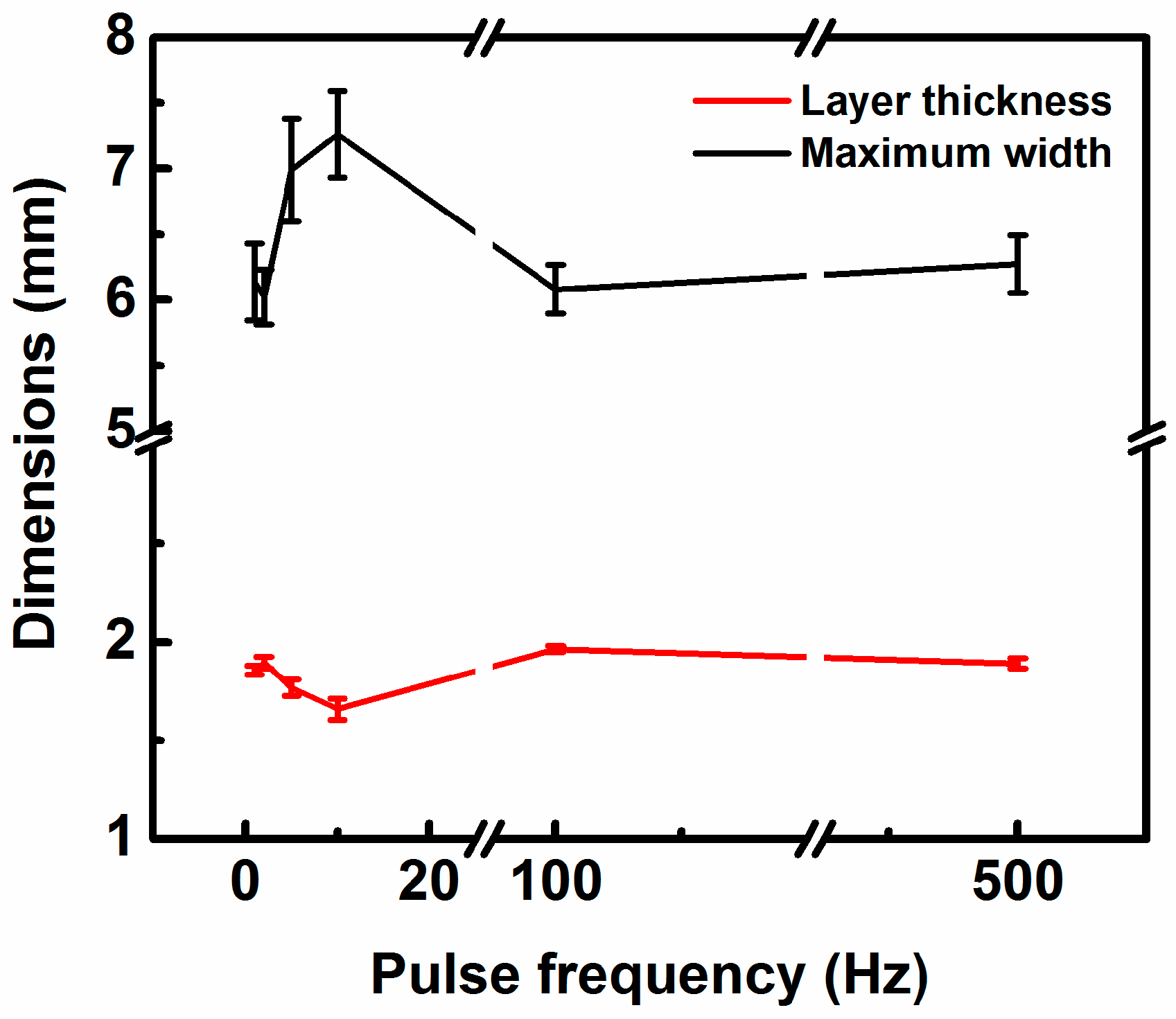
3.1. Macrostructure
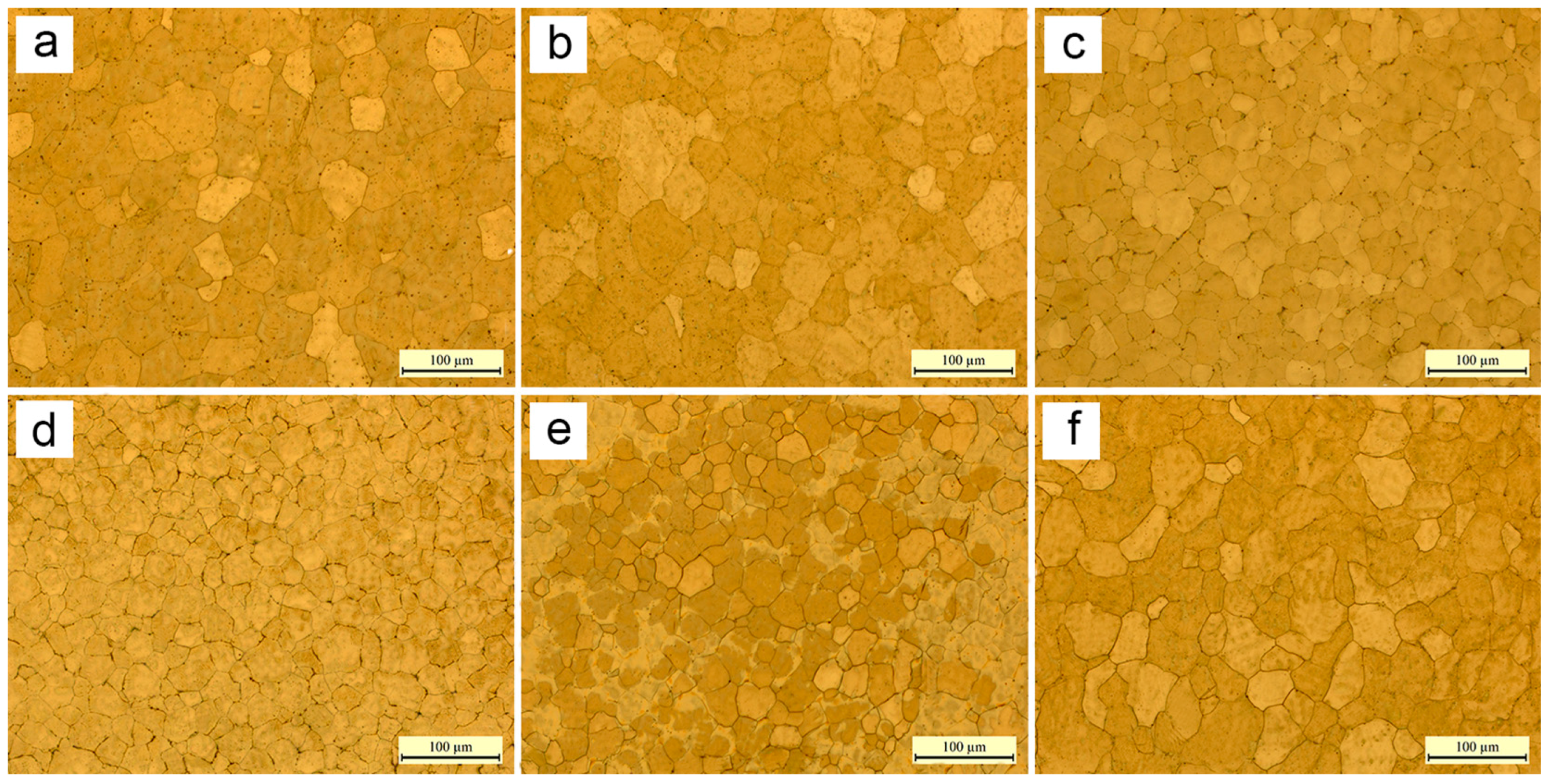
3.2. Microstructure
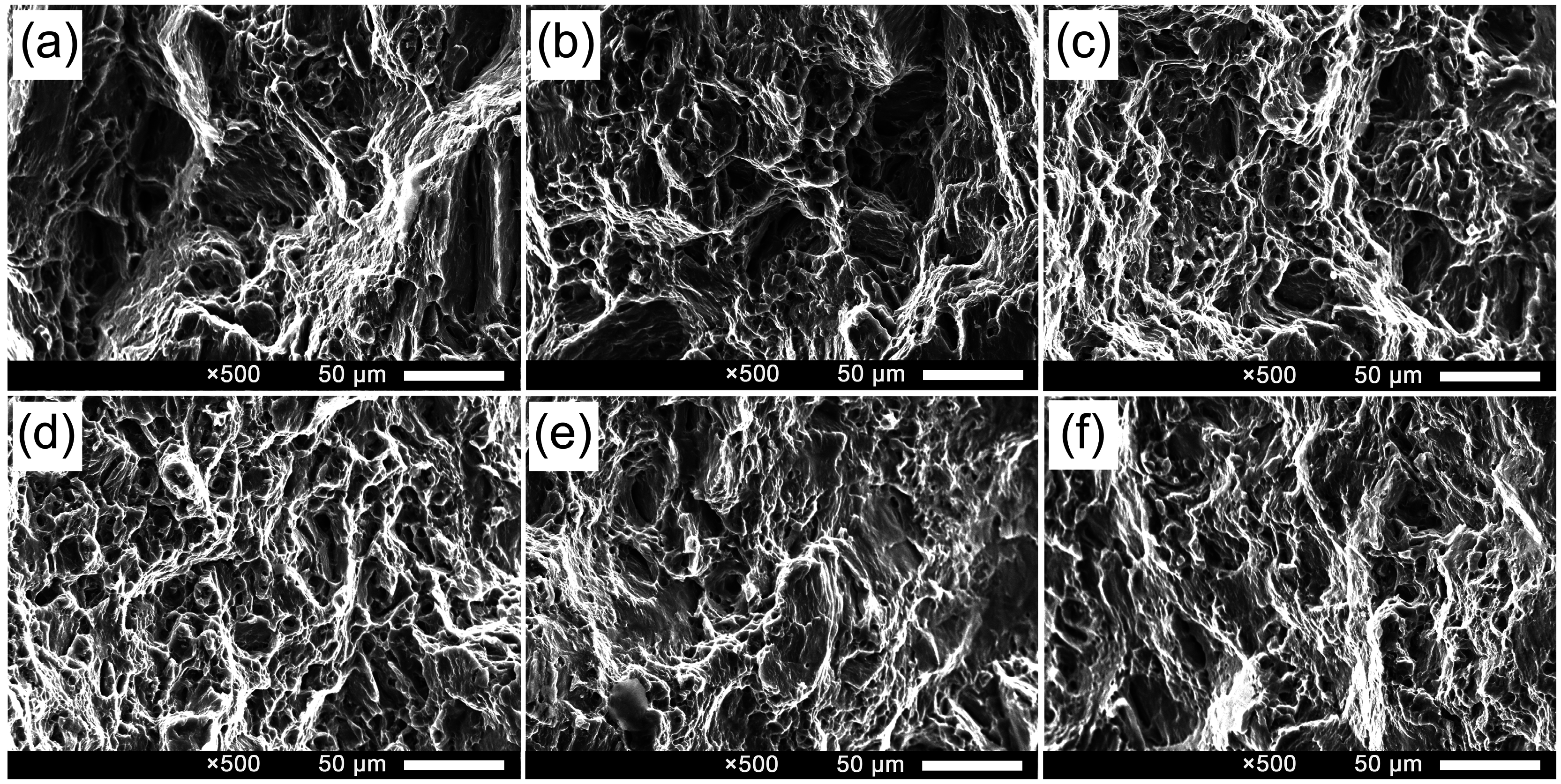
3.3. Tensile Properties
4. Conclusions
- (1)
- Fully dense AZ31 magnesium alloy components are successfully fabricated using WAAM. WAMM has the potential to manufacture magnesium alloys components.
- (2)
- Pulse frequency has a significant influence on macrostructure, microstructure and tensile properties of the wire arc additive manufactured samples. The shape of samples fabricated at 5 Hz and 10 Hz is odd due to the weld pool oscillating at its natural frequency. As the pulse frequency grows, weld pool oscillations increase and the cooling rate decreases leading to the fact that grain size decreases firstly and then increases, meanwhile, the grain aspect ratio is close to 1 firstly and then away from 1. Grain refinement reaches the maximum at 5–10 Hz, owing to resonance of the weld pool at these frequencies as mentioned previously. Correspondingly, tensile strength increases firstly and then decreases.
- (3)
- Fine grains and good tensile properties can be obtained at a certain pulse frequency. The samples fabricated at 5 Hz and 10 Hz contain finer equiaxed grains (21 μm) and exhibit higher ultimate tensile strength (260 MPa) and yield strength (102 MPa), which are similar to those of the forged AZ31 alloy. Moreover, the elongation of all samples is above 23%.
Acknowledgments
Author Contributions
Conflicts of Interest
References
- Haferkamp, H.; Boehm, R.; Holzkamp, U.; Jaschik, C.; Kaese, V.; Niemeyer, M. Alloy development, processing and applications in magnesium lithium alloys. Mater. Trans. 2001, 42, 1160–1166. [Google Scholar] [CrossRef]
- Mordike, B.L.; Ebert, T. Magnesium: Properties–applications–potential. Mater. Sci. Eng. A 2001, 302, 37–45. [Google Scholar] [CrossRef]
- Chai, F.; Zhang, D.; Li, Y. Effect of thermal history on microstructures and mechanical properties of az31 magnesium alloy prepared by friction stir processing. Materials 2014, 7, 1573–1589. [Google Scholar] [CrossRef]
- Zhang, J.; Xu, C.; Jing, Y.; Lv, S.; Liu, S.; Fang, D.; Zhuang, J.; Zhang, M.; Wu, R. New horizon for high performance mg-based biomaterial with uniform degradation behavior: Formation of stacking faults. Sci. Rep. 2015, 5, 13933. [Google Scholar] [CrossRef] [PubMed]
- Cao, X.; Xiao, M.; Jahazi, M.; Immarigeon, J.P. Continuous wave nd:Yag laser welding of sand-cast ze41a-t5 magnesium alloys. Mater. Manuf. Process. 2005, 20, 987–1004. [Google Scholar] [CrossRef]
- Feliu, J.S.; Samaniego, A.; Bermudez, E.; El-Hadad, A.; Llorente, I.; Galván, J. Effect of native oxide film on commercial magnesium alloys substrates and carbonate conversion coating growth and corrosion resistance. Materials 2014, 7, 2534–2560. [Google Scholar] [CrossRef]
- Padmanaban, G.; Balasubramanian, V. Optimization of pulsed current gas tungsten arc welding process parameters to attain maximum tensile strength in az31b magnesium alloy. Trans. Nonferr. Met. Soc. China 2011, 21, 467–476. [Google Scholar] [CrossRef]
- Easton, M.; Beer, A.; Barnett, M.; Davies, C.; Dunlop, G.; Durandet, Y.; Blacket, S.; Hilditch, T.; Beggs, P. Magnesium alloy applications in automotive structures. JOM 2008, 60, 57–62. [Google Scholar] [CrossRef]
- Zhu, X.; Liu, Y.; Wang, Q.; Liu, J. Influence of sulfate-reducing bacteria on the corrosion residual strength of an az91d magnesium alloy. Materials 2014, 7, 7118–7129. [Google Scholar] [CrossRef]
- Wei, K.; Gao, M.; Wang, Z.; Zeng, X. Effect of energy input on formability, microstructure and mechanical properties of selective laser melted az91d magnesium alloy. Mater. Sci. Eng. A 2014, 611, 212–222. [Google Scholar] [CrossRef]
- Wei, K.; Wang, Z.; Zeng, X. Influence of element vaporization on formability, composition, microstructure, and mechanical performance of the selective laser melted mg–zn–zr components. Mater. Lett. 2015, 156, 187–190. [Google Scholar] [CrossRef]
- Lancaster, R.; Davies, G.; Illsley, H.; Jeffs, S.; Baxter, G. Structural integrity of an electron beam melted titanium alloy. Materials 2016, 9, 470. [Google Scholar] [CrossRef]
- Wang, F.; Williams, S.; Rush, M. Morphology investigation on direct current pulsed gas tungsten arc welded additive layer manufactured ti6al4v alloy. Int. J. Adv. Manuf. Technol. 2011, 57, 597–603. [Google Scholar] [CrossRef] [Green Version]
- Frazier, W.E. Metal additive manufacturing: A review. J. Mater. Eng. Perform. 2014, 23, 1917–1928. [Google Scholar] [CrossRef]
- Chen, C.-H.; Liu, J.; Chua, C.-K.; Chou, S.-M.; Shyu, V.; Chen, J.-P. Cartilage tissue engineering with silk fibroin scaffolds fabricated by indirect additive manufacturing technology. Materials 2014, 7, 2104–2119. [Google Scholar] [CrossRef]
- Antonysamy, A.A.; Meyer, J.; Prangnell, P.B. Effect of build geometry on the β-grain structure and texture in additive manufacture of Ti 6Al 4V by selective electron beam melting. Mater. Charact. 2013, 84, 153–168. [Google Scholar] [CrossRef]
- Zhang, J.; Wang, X.; Paddea, S.; Zhang, X. Fatigue crack propagation behaviour in wire + arc additive manufactured Ti-6Al-4V: Effects of microstructure and residual stress. Mater. Des. 2016, 90, 551–561. [Google Scholar] [CrossRef]
- Lin, J.J.; Lv, Y.H.; Liu, Y.X.; Xu, B.S.; Sun, Z.; Li, Z.G.; Wu, Y.X. Microstructural evolution and mechanical properties of Ti-6Al-4V wall deposited by pulsed plasma arc additive manufacturing. Mater. Des. 2016, 102, 30–40. [Google Scholar] [CrossRef]
- Liu, C.; Lu, Y.; Tian, X.; Liu, D. Influence of continuous grain boundary α on ductility of laser melting deposited titanium alloys. Mater. Sci. Eng. A 2016, 661, 145–151. [Google Scholar] [CrossRef]
- Chi, C.N.; Savalani, M.; Man, H.C. Fabrication of magnesium using selective laser melting technique. Rapid Prototyp. J. 2011, 17, 479–490. [Google Scholar]
- Hu, D.; Wang, Y.; Zhang, D.; Hao, L.; Jiang, J.; Li, Z.; Chen, Y. Experimental investigation on selective laser melting of bulk net-shape pure magnesium. Mater. Manuf. Process. 2015, 30, 1298–1304. [Google Scholar] [CrossRef]
- Zhang, B.; Liao, H.; Coddet, C. Effects of processing parameters on properties of selective laser melting Mg–9%Al powder mixture. Mater. Des. 2012, 34, 753–758. [Google Scholar] [CrossRef]
- Al-Kazzaz, H.; Medraj, M.; Cao, X.; Jahazi, M. Nd:Yag laser welding of aerospace grade ZE41A magnesium alloy: Modeling and experimental investigations. Mater. Chem. Phys. 2008, 109, 61–76. [Google Scholar] [CrossRef]
- Wang, F.; Williams, S.; Colegrove, P.; Antonysamy, A.A. Microstructure and mechanical properties of wire and arc additive manufactured Ti-6Al-4V. Metall. Mater. Trans. A 2012, 44, 968–977. [Google Scholar] [CrossRef]
- Martina, F.; Mehnen, J.; Williams, S.W.; Colegrove, P.; Wang, F. Investigation of the benefits of plasma deposition for the additive layer manufacture of Ti-6Al-4V. J. Mater. Process. Technol. 2012, 212, 1377–1386. [Google Scholar] [CrossRef] [Green Version]
- Ding, D.; Pan, Z.; Cuiuri, D.; Li, H. Wire-feed additive manufacturing of metal components: Technologies, developments and future interests. Int. J. Adv. Manuf. Technol. 2015, 81, 465–481. [Google Scholar] [CrossRef]
- Brandl, E.; Baufeld, B.; Leyens, C.; Gault, R. Additive manufactured Ti-6Al-4V using welding wire: Comparison of laser and arc beam deposition and evaluation with respect to aerospace material specifications. Phys. Proced. 2010, 5, 595–606. [Google Scholar] [CrossRef]
- Shen, C.; Pan, Z.; Ma, Y.; Cuiuri, D.; Li, H. Fabrication of iron-rich Fe–Al intermetallics using the wire-arc additive manufacturing process. Addit. Manuf. 2015, 7, 20–26. [Google Scholar] [CrossRef]
- Xiong, J.; Zhang, G.; Zhang, W. Forming appearance analysis in multi-layer single-pass gmaw-based additive manufacturing. Int. J. Adv. Manuf. Technol. 2015, 80, 1767–1776. [Google Scholar] [CrossRef]
- Ding, D.; Pan, Z.; van Duin, S.; Li, H.; Shen, C. Fabricating superior nial bronze components through wire arc additive manufacturing. Materials 2016, 9, 652. [Google Scholar] [CrossRef]
- Bermingham, M.J.; Kent, D.; Zhan, H.; StJohn, D.H.; Dargusch, M.S. Controlling the microstructure and properties of wire arc additive manufactured Ti-6Al-4V with trace boron additions. Acta Mater. 2015, 91, 289–303. [Google Scholar] [CrossRef]
- Wang, H.; Jiang, W.; Ouyang, J.; Kovacevic, R. Rapid prototyping of 4043 Al-alloy parts by VP-GTAW. J. Mater. Process. Technol. 2004, 148, 93–102. [Google Scholar] [CrossRef]
- Ouyang, J.H.; Wang, H.; Kovacevic, R. Rapid prototyping of 5356-aluminum alloy based on variable polarity gas tungsten arc welding: Process control and microstructure. Mater. Manuf. Process. 2002, 17, 103–124. [Google Scholar] [CrossRef]
- Subravel, V.; Padmanaban, G.; Balasubramanian, V. Effect of pulse frequency on tensile properties and microstructural characteristics of gas tungsten arc welded AZ31B magnesium alloy. Trans. Indian Inst. Met. 2014, 68, 353–362. [Google Scholar] [CrossRef]
- Padmanaban, G.; Balasubramanian, V. Influences of pulsed current parameters on mechanical and metallurgical properties of gas tungsten arc welded AZ31B magnesium alloys. Met. Mater. Int. 2011, 17, 831–839. [Google Scholar] [CrossRef]
- Subravel, V.; Padmanaban, G.; Balasubramanian, V. Effect of welding speed on microstructural characteristics and tensile properties of gta welded AZ31B magnesium alloy. Trans. Nonferr. Met. Soc. China 2014, 24, 2776–2784. [Google Scholar] [CrossRef]
- Liu, C.M.; Wang, H.M.; Tian, X.J.; Tang, H.B.; Liu, D. Microstructure and tensile properties of laser melting deposited Ti–5Al–5Mo–5V–1Cr–1Fe near β titanium alloy. Mater. Sci. Eng. A 2013, 586, 323–329. [Google Scholar] [CrossRef]
- Sharir, Y.; Pelleg, J.; Grill, A. Effect of arc vibration and current pulses on microstructure and mechanical properties of tig tantalum welds. Met. Technol. 2013, 5, 190–196. [Google Scholar] [CrossRef]
- Kou, S. Welding Metallurgy, 2nd ed.; John Wiley & Sons, Inc.: Hoboken, NJ, USA, 2003. [Google Scholar]
- ASTM; B91-12; ASTM International: West Conshohocken, PA, USA, 2012.
- Jia, W.; Ma, L.; Tang, Y.; Le, Q.; Fu, L. Relationship between microstructure and properties during multi-pass, variable routes and different initial temperatures hot flat rolling of AZ31B magnesium alloy. Mater. Des. 2016, 103, 171–182. [Google Scholar] [CrossRef]
- Zhu, Y.Z.; Wang, S.Z.; Li, B.L.; Yin, Z.M.; Wan, Q.; Liu, P. Grain growth and microstructure evolution based mechanical property predicted by a modified hall–petch equation in hot worked Ni76Cr19AlTiCo alloy. Mater. Des. 2014, 55, 456–462. [Google Scholar] [CrossRef]


| Deposition Parameters | Values |
|---|---|
| Type of welding current | alternating current (AC) |
| Alternating current frequency | 400 Hz |
| Electrode positive (EP) | 136 A |
| Electrode negative (EN) | 91 A |
| Electrode negative ratio | 80% |
| Pulse frequency | 1, 2, 5, 10, 100 and 500 Hz |
| Peak time ratio | 50% |
| Base-to-peak current ratio | 30% |
| Wire feed rate | 2 m/min |
| Deposition speed | 200 mm/min |
| Argon | 99.999% purity |
| Shield gas flow rate | 20 L/min |
| Arc length | 3 mm |
| Tungsten electrode diameter | 2.4 mm |
| Pulse Frequency (Hz) | Grain Size (μm) | Grain Aspect Ratio |
|---|---|---|
| 1 | 31 ± 4 | 1.09 ± 0.04 |
| 2 | 23 ± 1 | 1.15 ± 0.06 |
| 5 | 21 ± 1 | 1.02 ± 0.12 |
| 10 | 21 ± 1 | 0.98 ± 0.11 |
| 100 | 39 ± 4 | 1.22 ± 0.21 |
| 500 | 37 ± 3 | 1.14 ± 0.10 |
| Pulse Frequency (Hz) | UTS (MPa) | YS (MPa) | EL (%) |
|---|---|---|---|
| 1 | 229 ± 3 | 90 ± 1 | 26.3 ± 0.3 |
| 2 | 232 ± 1 | 89 ± 1 | 26.7 ± 1.2 |
| 5 | 258 ± 5 | 100 ± 3 | 25.6 ± 3.1 |
| 10 | 263 ± 5 | 104 ± 5 | 23.0 ± 3.7 |
| 100 | 221 ± 11 | 82 ± 6 | 23.4 ± 5.8 |
| 500 | 231 ± 5 | 79 ± 2 | 27.3 ± 0.3 |
© 2016 by the authors; licensee MDPI, Basel, Switzerland. This article is an open access article distributed under the terms and conditions of the Creative Commons Attribution (CC-BY) license (http://creativecommons.org/licenses/by/4.0/).
Share and Cite
Guo, J.; Zhou, Y.; Liu, C.; Wu, Q.; Chen, X.; Lu, J. Wire Arc Additive Manufacturing of AZ31 Magnesium Alloy: Grain Refinement by Adjusting Pulse Frequency. Materials 2016, 9, 823. https://doi.org/10.3390/ma9100823
Guo J, Zhou Y, Liu C, Wu Q, Chen X, Lu J. Wire Arc Additive Manufacturing of AZ31 Magnesium Alloy: Grain Refinement by Adjusting Pulse Frequency. Materials. 2016; 9(10):823. https://doi.org/10.3390/ma9100823
Chicago/Turabian StyleGuo, Jing, Yong Zhou, Changmeng Liu, Qianru Wu, Xianping Chen, and Jiping Lu. 2016. "Wire Arc Additive Manufacturing of AZ31 Magnesium Alloy: Grain Refinement by Adjusting Pulse Frequency" Materials 9, no. 10: 823. https://doi.org/10.3390/ma9100823