Article

Influence Factors Analysis on the Modal Characteristics of Irregularly-Shaped Bridges Based on a Free-Interface Mode Synthesis Algorithm

College of Transportation, Jilin University, Changchun 130025, China
*
Author to whom correspondence should be addressed.
Algorithms 2017, 10(2), 62; https://doi.org/10.3390/a10020062
Submission received: 24 December 2016 / Revised: 23 May 2017 / Accepted: 24 May 2017 / Published: 28 May 2017

Abstract

:
In order to relieve traffic congestion, irregularly-shaped bridges have been widely used in urban overpasses. However, the analysis on modal characteristics of irregularly-shaped bridges is not exhaustive, and the effect of design parameters on modal characteristics will be deeply investigated in future studies. In this paper, a novel strategy based on a free-interface mode synthesis algorithm is proposed to evaluate the parameters’ effect on the modal characteristics of irregularly-shaped bridges. First, a complicated, irregularly-shaped bridge is divided into several substructures based on its properties. Then, the modal characteristics of the overall structure can be obtained, only by a few low-order modal parameters of each substructure, using a free-interface mode synthesis method. A numerical model of a typical irregularly-shaped bridge is employed to verify the effectiveness of the proposed strategy. Simulation results reveal that the free-interface mode synthesis method possesses favorable calculation accuracy for analyzing the modal characteristics of irregularly-shaped bridges. The effect of design parameters such as ramp curve radius, diaphragm beam stiffness, cross-section feature, and bearing conditions on the modal characteristics of an irregularly-shaped bridge is evaluated in detail. Analysis results can provide references for further research into and the design of irregularly-shaped bridges.

1. Introduction

With the development of transportation infrastructure, urban road network density is increasing, and road intersections are worsening. Urban overpasses are an effective way to solve this problem. In the design and planning of urban overpasses, curved bridges can make road alignment smooth and beautiful. They also reduce the effect on ground transportation and play an importation role in relieving urban traffic congestion [1,2]. Considering restrictions of topography, space, and other factors, irregular crotches with variable width, slope, and curvature are usually adopted to connect main bridges and ramps. Irregularly-shaped bridges, such as the one shown in Figure 1a, become the main structural form of urban overpass. However, a number of urban overpasses with irregular crotches, such as the one shown in Figure 1b, have been destroyed while in operation in China [3]. It indicates that design methods and techniques are not mature in practice. Research on the modal characteristics of irregularly-shaped bridges can provide references for irregularly-shaped bridge design, and gradually improve the safety operations of these structures.
The cross-section of an irregularly-shaped bridge mainly adopts thin-walled box girders [4]. It increases the complexity of analyzing the modal characteristics of irregularly-shaped bridges due to the combinational effect of bending and torsion in thin-walled box girders. A number of studies have been conducted on the calculation principles and analysis methods for the modal characteristics of curved thin-walled box girder bridges [5,6,7,8,9]. However, the main girder and ramp mutually contact and restrict each other at the crotch of an irregularly-shaped bridge. Its dynamic characteristics present a complicated coupling effect with bending and torsion, which are different from the conventional curved structure.
Finite element analysis provides an effective way to analyze the modal characteristics of this structure. Yoon et al. [10] proposed a curved beam element with seven degrees of freedom at each node, and put forward the formula of element stiffness and mass matrices to analyze the modal characteristics of thin-walled curved beams. Sapountzakis et al. [11] dispersed the curved beam by straight line elements—considering warping and shear deformation—to calculate the structural modal characteristics, which verified the accuracy of the curved beam model to replace broken lines. Lu et al. [4] analyzed the modal characteristics of irregularly-shaped bridges using shell elements. A comparative analysis with a grillage method is performed to prove the accuracy of a proposed method. However, the complex structure is divided into a large number of units with multiple degrees of freedom, which would seriously affect the computational efficiency and accuracy of the finite element method. Especially, when the bridge’s parameters change, the finite element model reconstruction increases the analysis’ complexity. A substructure method is widely used because it can minimize the size of matrices, and reduces the expense of computational time. The basic idea of the substructure method is to decompose the complex structure into several substructures according to structural features. In addition, analysis on each respective substructure is performed. Overall modal characteristics can be obtained by comprehensively assembling all the substructures according to boundary conditions [12]. If the local design parameter is changed in the structural model, only the modal characteristics of the corresponding substructure should be recalculated. It could effectively improve operational efficiency and achieve overall analysis of the complex structure.
As an important component of substructure methods, the dynamic substructure method can take advantage of the modal characteristics of each subsystem with a simple calculation process to finally obtain the modal characteristics of the whole structure. Since the 1960s, the dynamic substructure method has been developing rapidly [13]. Especially in recent years, this method has been increasingly applied in the field of Bridges. Biondi et al. [14] presented a substructure approach for analyzing the dynamic response of the train–rails–bridge system. It regards the train, rail, and bridge deck as three substructures, and simultaneously computes the dynamic responses of the train, rail, and bridge to analyze vehicle–bridge dynamic interaction. Li et al. [15] proposed the damage identification strategy based on the dynamic substructure method, which divided the complex structure into several substructures, and identified the structural damage based on the dynamic response of the substructures under moving load excitation. Kong et al. [12] demonstrated a new substructure approach to analyzing the vehicle-induced vibration of long-span hybrid cable-stayed bridges. It divided the bridge into many substructures with a reasonable length and condensed the substructures model in detail with refined mesh into super elements. It used the dynamic substructure mode synthesis method to analyze the vehicle-induced dynamic response under deterministic flows.
Based on different solutions to the problem, dynamic substructure methods can be divided into the component mode synthesis (CMS) method, the interface displacement synthesis method, the migration substructure method, and the super element method. CMS is widely used as the most mature theory among them [16,17,18]. Based on the differences between some treatments to the interface, CMS can be divided into the fixed interface component mode synthesis method, the free interface component mode synthesis method, and the hybrid component mode synthesis method. The free interface component mode synthesis method proposed by Hou has been developing rapidly and is widely used [19,20,21,22]. It does not contain the interface node displacement coordinates in the comprehensive equation, which is convenient to combine and verify with the experimental mode technique. The double coordinate free-interface mode synthesis method possesses outstanding advantages in structural modal analysis with high calculation accuracy.
The free-interface mode synthesis method is gradually applied to the modal analysis of bridges. However, there is very little investigation on the modal characteristics of irregularly-shaped bridges based on this method. In this paper, the double coordinate free-interface mode synthesis method is adopted to analyze the modal characteristics of an irregularly-shaped bridge. Ramp curve radius, crotches diaphragm beam stiffness, cross-section feature, and bearing conditions are selected as feature parameters. Their influence on the modal characteristics of an overall irregularly-shaped bridge is analyzed. The analysis can provide a reference for design and can improve the safety standard. However, there is a long distance from the parameters’ impact on the modal characteristics of the irregularly-shaped bridge to the impact on dynamic behaviours. The critical analysis on the corresponding structural dynamic response beyond modal analysis will be a matter for future studies. Additionally, the parameters’ impact on the dynamic responses of irregularly-shaped bridges considering nonlinear behaviours is also important [23,24]. Pushover analysis on the irregularly-shaped bridge will be conducted in future studies to enrich the conclusion [25].

2. Theoretical Background

2.1. Mode Synthesis Method

In structural modal analysis, a motion equation containing mass, stiffness and damping matrices should be solved. In order to reduce the computational requirements, the motion equation can be replaced by a low-order equation through finding the presumed mode sets based on the Rayleigh–Ritz method [26]. The mode synthesis method can find reasonable presumed mode sets by substructures to achieve structural modal analysis. The procedures of the mode synthesis method for analyzing structural modal characteristics are illustrated as follows. First, the original complex structure is divided into simple substructures based on construction features. The modal analysis is performed independently for each substructure by use of the finite element method. Second, enough modes in modal coordinates are extracted to represent the modal characteristics of the substructure. The transformation from physical coordinates to modal coordinates is conducted to obtain the modal coordinates of the coupling system. Third, the dependent modal coordinates are eliminated based on compatible conditions between substructures to transform the modal coordinates of substructure into generalized ones. The generalized motion equation is established by only independent generalized coordinates. Fourth, the motion equation under free vibration after mode synthesis is solved to obtain the modal parameters according to the generalized coordinates. Fifth, the eigenvector matrix of the system is transformed from generalized coordinates to physical ones in order to obtain the results of each substructure under physical coordinates.
In the process of modal coordinate transformation, a few low-order modes are selected to represent a substructure, which makes the number of independent generalized coordinates for the whole system less than the number of degrees of freedom in the finite element model of the structure. This is the main reason for obtaining the reduced-order motion equation.

2.2. Double Coordinate Free-Interface Mode Synthesis Method

The double coordinate free-interface mode synthesis method adopts both displacement and force compatible conditions. A structure with A and B substructures is used to illustrate the principle of this method.
The low-order free interface main modes and the residual adhesion modes of substructures are used to construct presumed mode sets. First, transformation from the physical coordinates to modal coordinates is conducted for each substructure, as follows:
{ u ( z ) } = { u i ( z ) u j ( z ) } = [ ϕ ( z ) ] { p ( z ) } = [ ϕ l ( z ) ψ s ( z ) ] { p l ( z ) p s ( z ) } = [ ϕ i l ( z ) ψ i s ( z ) ϕ j l ( z ) ψ j s ( z ) ] { p l ( z ) p s ( z ) }
where z = A , B ; { u i ( z ) } , { u j ( z ) } are the physical coordinates of the internal and interfacial degree of freedoms (DOFs), respectively; { p l ( z ) } and { p s ( z ) } are independent and dependent modal coordinates, respectively; [ ϕ ( z ) ] is the coordinate transformation matrix; [ ϕ l ( z ) ] is the main mode set; and [ ψ s ( z ) ] is the residual adhesion mode set.
[ ψ s ( z ) ] = ( [ G ( z ) ] [ ϕ l ( z ) ] [ λ l ( z ) ] 1 [ ϕ l ( z ) ] T ) [ O i × j I j × j ]
where [ G ( z ) ] is the flexibility matrix of the substructure; [ λ l ( z ) ] is the low-order eigenvalue matrix; [ O i × j ] is the zero matrix and [ I j × j ] is the unit matrix; i represents the number of internal DOFs; j is the number of interfacial DOFs.
The modal coordinate set { p } of the system can be divided as follows.
{ p } = [ { p l ( A ) } T { p s ( A ) } T { p l ( B ) } T { p s ( B ) } T ] T
The modal coordinate set { p } is transformed by a positioning matrix to rearrange the elements
{ p ¯ } = [ { p s ( A ) } T { p s ( B ) } T { p l ( A ) } T { p l ( B ) } T ] T = [ p s T p l T ] T
{ p } = [ E ] { p ¯ }
where [ E ] is the positioning matrix, which can be represented by
[ E ] = [ O O I O I O O O O O O I O I O O ] .
The node force of a substructure is equal to the interface force between substructures when the structure is in low-order free vibration.
{ F ( z ) } = { O i f j ( z ) }
By substituting the modal coordinates into the motion equation, and ignoring the influence of inertial force, it can be obtained that
[ ψ s ( z ) ] T [ k ( z ) ] [ ψ s ( z ) ] { p s ( z ) } = [ ψ s ( z ) ] T { O i f j ( z ) }
( [ ϕ j s ( z ) ] [ λ s ( z ) ] 1 [ ϕ j s ( z ) ] T ) ( { p s ( z ) } { f j ( z ) } ) = { O } .
Therefore,
{ p s ( z ) } = { f j ( z ) } .
The interface compatible conditions are obtained as follows.
{ { u j ( A ) } = { u j ( B ) } { p s ( A ) } = { p s ( B ) }
The constraint equation of the modal coordinates is
[ C ] { p ¯ } = { 0 } .
Additionally,
C = [ ϕ j l ( A ) ψ j s ( A ) O I ϕ j l ( B ) ψ j s ( B ) O I ] = [ C s s C s l ]
where [ C s s ] and [ C s l ] are constraint sub-matrices corresponding to the dependent and independent modal coordinates, respectively.
The second transformation is carried out by eliminating the dependent modal coordinates.
{ p ¯ } = { [ C s s ] 1 [ C s l ] I } { p l } = [ S ] { p l }
where [ S ] is the transformation matrix of independent coordinates.
The presumed generalized coordinates are { q } = { p l } , then
{ p } = [ E ] { p ¯ } = [ E ] [ S ] { q }
[ M ] = [ S ] T [ E ] T [ ϕ ] T [ m ] [ ϕ ] [ E ] [ S ]
[ K ] = [ S ] T [ E ] T [ ϕ ] T [ k ] [ ϕ ] [ E ] [ S ]
where [ M ] is the modal mass matrix and [ K ] is the modal stiffness matrix.
The modal parameters of the system can be calculated by solving the motion equation in generalized coordinates.
[ M ] { q ¨ } + [ K ] { q } = { 0 }
The physical coordinates can be obtained through transforming back from the generalized ones. The results of each substructure in physical coordinates can be calculated as follows.
{ u ( z ) } = [ ϕ ( z ) ] [ E ] [ S ] { q }

3. Substructure Model of Irregularly-Shaped Bridges

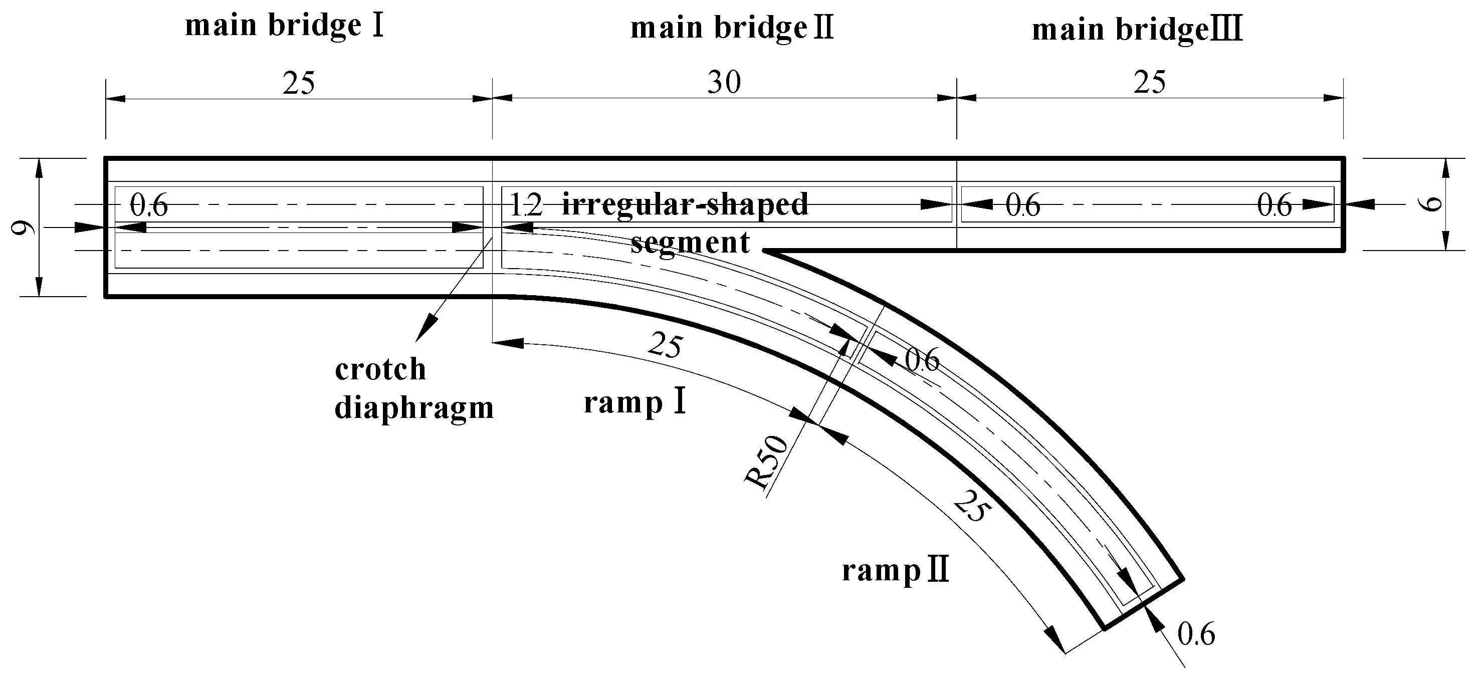
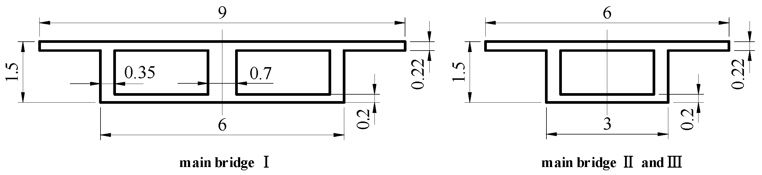
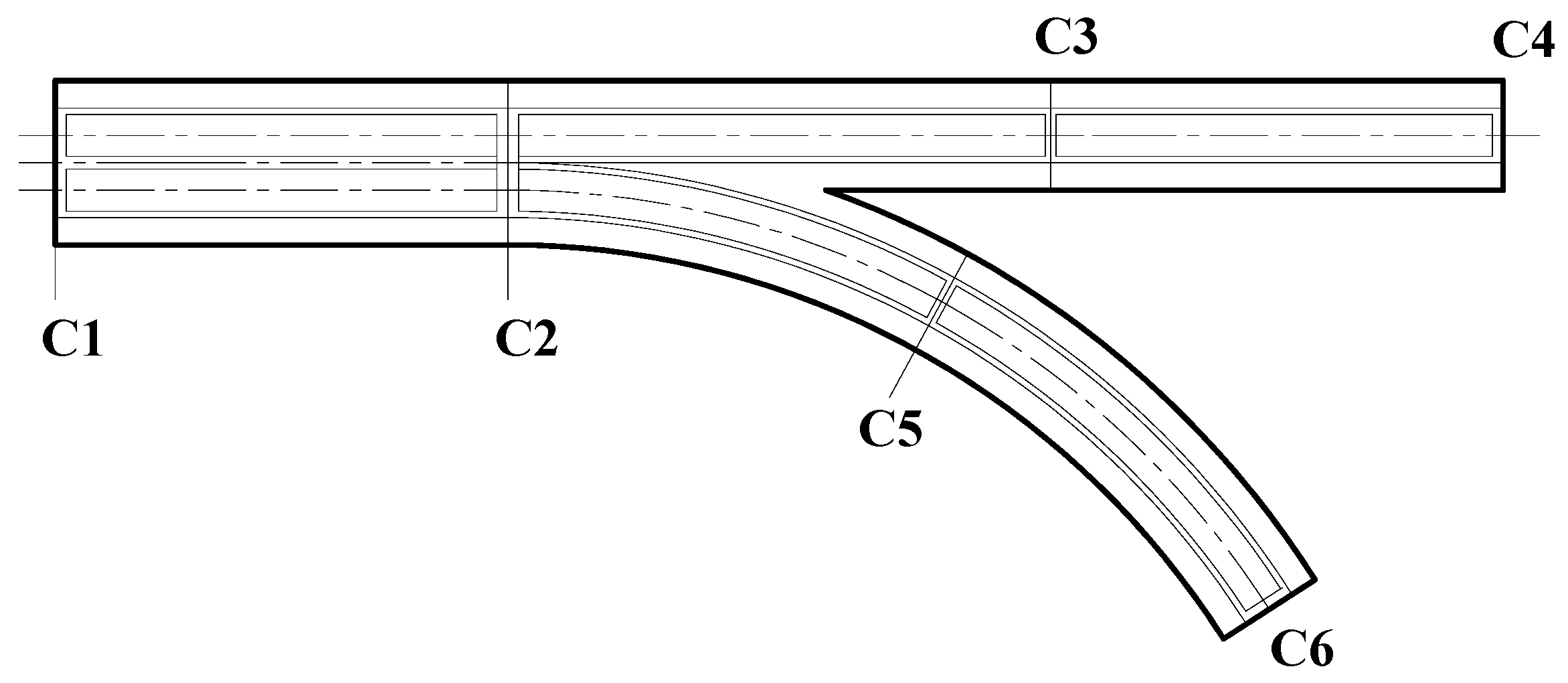
3.1. Irregularly-Shaped Bridge Model

A typical irregularly-shaped pre-stressed concrete continuous box girder bridge, as shown in Figure 2, is selected as the research object [1,3]. This bridge consists of a straight three-span continuous girder (main bridge), and a curved two-span continuous girder (ramp), which are widely used in irregularly-shaped thin-wall box girder bridges. The spans of the main bridge are 25 m + 30 m + 25 m, and the distance from the bifurcation position to the left side of the main bridge is 25 m. The first span of the main bridge is a single-box double-room girder with a constant section of 9 m in width. The other spans of the main bridge are a single-box single-room girder with a constant section of 6 m in width. The cross-section of the ramp is the same as the second span of the main bridge, which is shown in Figure 3. The ramp radius is R = 50 m, and spans are 25 m + 25 m. The diaphragm beams are set at the bearing position of each span. The width of the diaphragm beam at the bifurcation position is 1.2 m, and the others are 0.6 m. The bridge is composed of C50 concrete, and the material parameters are modulus of elasticity E = 35   GPa , modulus of shear G = 0.4 E , density ρ = 2600   kg / m 3 and Poisson ratio μ = 0.2 . The bearing positions of the typical irregularly-shaped bridge are shown in Figure 4. The corresponding bearing conditions are listed in Table 1.

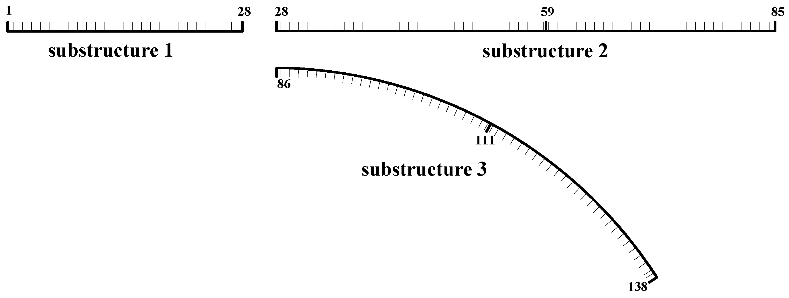
3.2. Substructure Establishment

The whole bridge structure is divided into three substructures at the bifurcation position, including the main bridge before separation (substructure 1), the main bridge after separation (substructure 2), and the ramp (substructure 3). The substructures are simulated by space beam elements with six nodes. The numerical model of the whole irregularly-shaped bridge includes 137 elements and 138 nodes, as shown in Figure 5.

4. Accuracy Evaluation of the Double Coordinate Free-Interface Mode Synthesis Method

First, the modal characteristics of the irregularly-shaped bridge are calculated based on the traditional finite element analysis theory, where the eigenvalue equation is solved by a MATLAB program based on the construction of stiffness and mass matrices. In order to verify the accuracy of the double coordinate free-interface mode synthesis method, the first 20 free interface main modes and the corresponding residual adhesion modes are selected as the modal matrix for the first coordinate transformation to calculate all the modal characteristics. The computational time of the double coordinate free-interface mode synthesis method decreases from 343 s to 125 s by use of the traditional finite element analysis method. The first 10 modal frequencies of the whole structure are calculated and listed in Table 2.
As can be seen in Table 2, the modal frequencies obtained by the double coordinate free-interface mode synthesis method are close to the results of the finite element analysis, and the relative errors are negligible. These results indicate that the double coordinate free-interface mode synthesis method is effective to solve the modal characteristics of the irregularly-shaped bridge.

5. Influence Factors Analysis on the Modal Characteristics of the Irregularly-Shaped Bridge

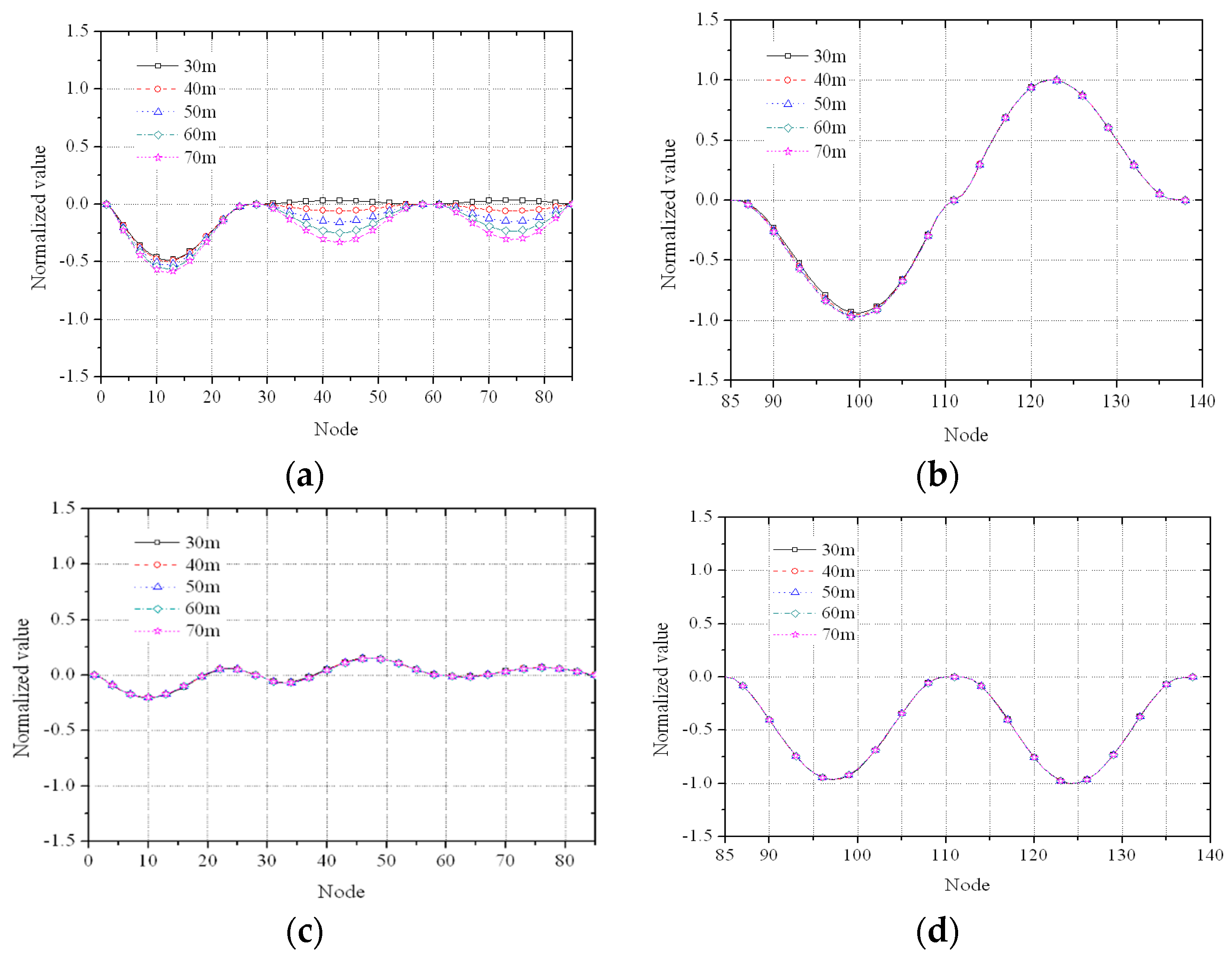
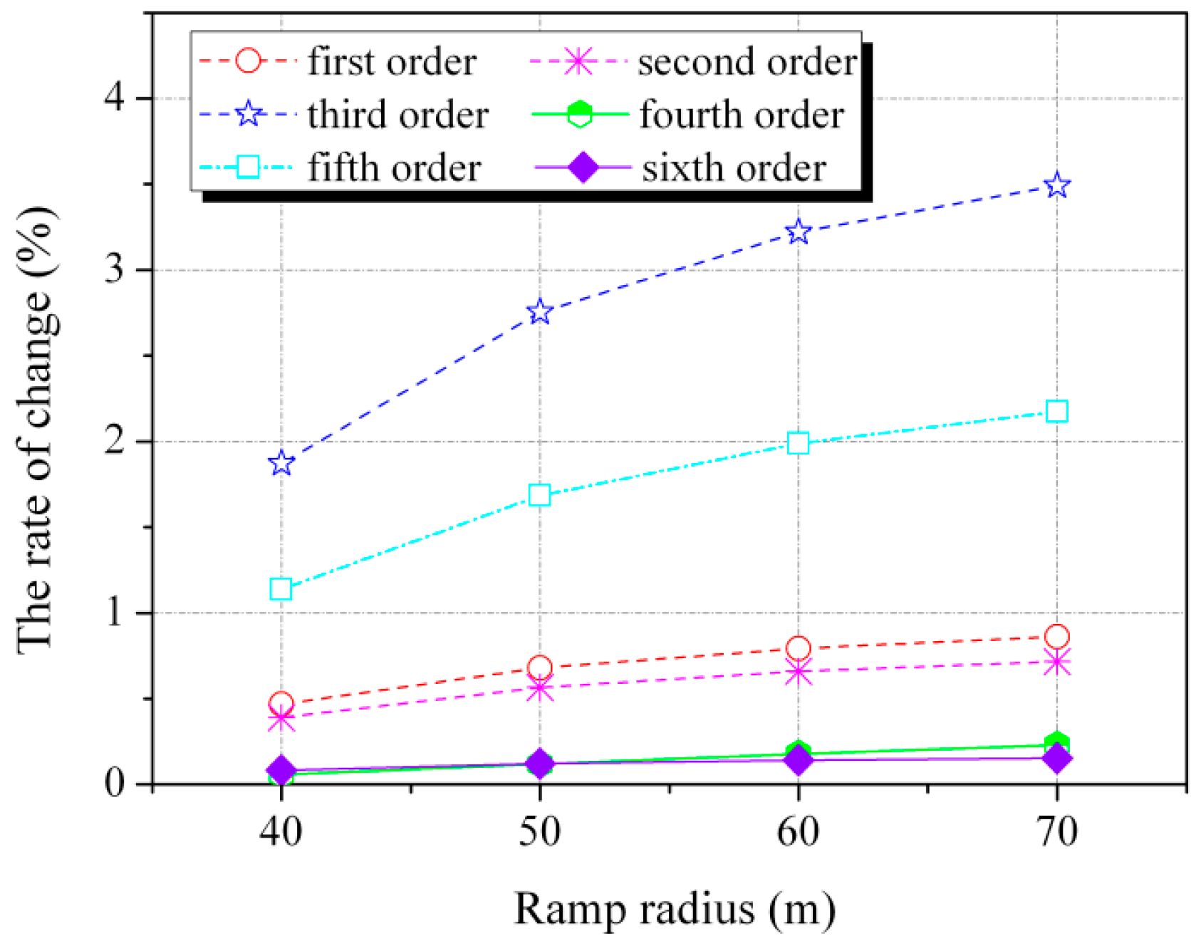
5.1. Ramp Curve Radius

The design parameters of substructures 1 and 2 are not changed. The length of the ramp keeps constant and the radii of curvature are 30 m, 40 m, 50 m, 60 m and 70 m, respectively. The modal characteristics are analyzed with different curve radii to obtain the first 10 modal frequencies and the first six vertical bending mode shapes.
The change rates of modal frequencies of the irregularly-shaped bridge with different ramp radii with respect to that of radius 30 m are shown in Figure 6. As can be seen from the results, modal frequencies of vertical bending mode increase with ramp radii. The change rates of the third and fifth modal frequencies are obvious, while the others are relatively small. As for the mode shapes, vertical bending of the ramp is the main vibration style in the third and fifth modes (shown in Figure 7), while vertical bending of the main bridge is obvious in other modes. Therefore, the effects of ramp radii are more significant in the third and fifth modes, which are coincident with the change of modal frequencies.
The first five mode shapes are all vertical bending vibration. The modal frequencies and the corresponding vibration shapes of the sixth and seventh modes are listed in Table 3. As can be seen, the lateral bending modes of the ramp first appear at larger radii such as 60 m and 70 m, which demonstrates that the capability of the ramp to resist lateral bending vibration gradually reduces with the increasing of radii. Therefore, the increasing of the ramp’s radii will adversely affect the lateral stiffness in the design of the irregularly-shaped bridge.

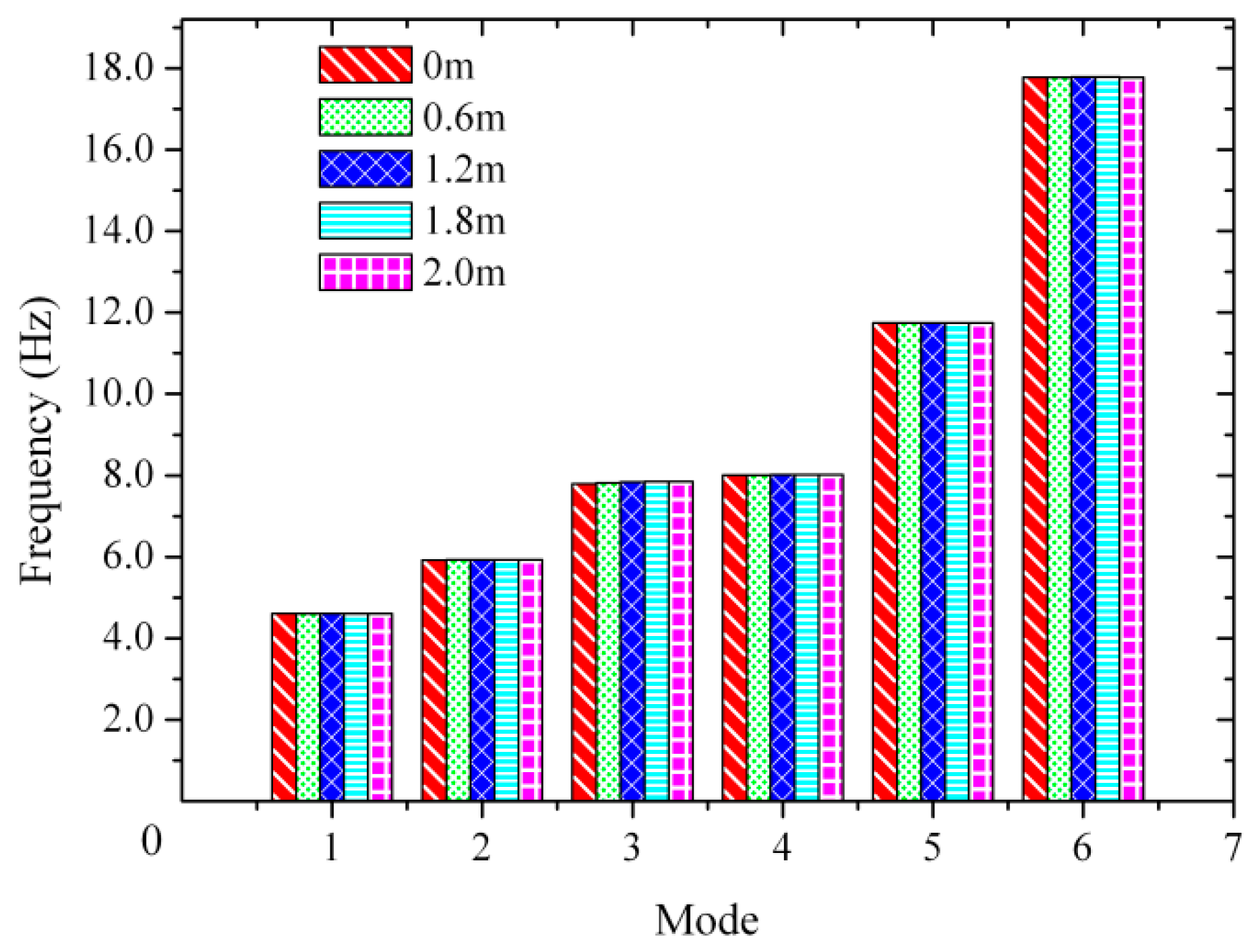
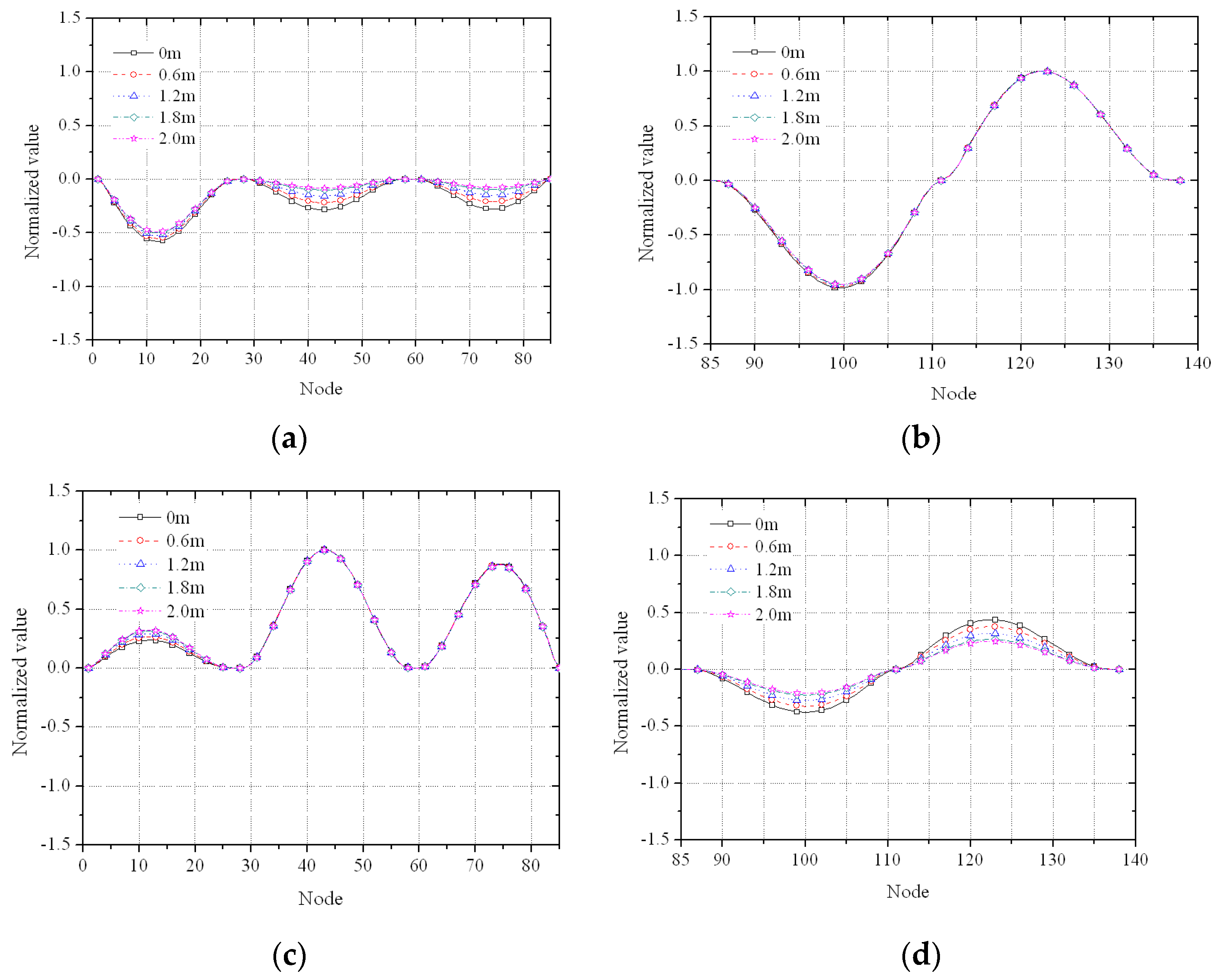
5.2. Crotch Diaphragm Stiffness

The design parameters of substructures 2 and 3 remain unchanged, while the stiffness of the crotch’s diaphragm is varied by adjusting its width in substructure 1. The modal characteristics are calculated with the widths of 0 m, 0.6 m, 1.2 m, 1.8 m and 2 m, respectively. The first six modal frequencies of vertical bending modes are shown in Figure 8.
The third and fourth vertical bending mode shapes with more obvious changes are shown in Figure 9.
As can be seen from Figure 8 and Figure 9, diaphragm stiffness has an insignificant effect on modal frequencies and low-order mode shapes, with the exception of the third and fourth modes. The crotch of the irregularly-shaped bridge is the inflection point of the third and fourth mode shapes. The width of the diaphragm decides its local stiffness. Ramp vertical bending is the main vibration form in the third mode. The main bridge vibration weakens with the increasing of diaphragm stiffness. On the contrary, the main bridge vertical bending is the main vibration form in the fourth mode. Ramp vibration weakens with the increasing of diaphragm stiffness. The increasing of diaphragm stiffness can decrease the vibration in the third and fourth modes of the irregularly-shaped bridge. However, the diaphragm at the crotch position is a local component, which generally has little effect on the modal characteristics of the whole irregularly-shaped bridge.

5.3. Cross-Section Features

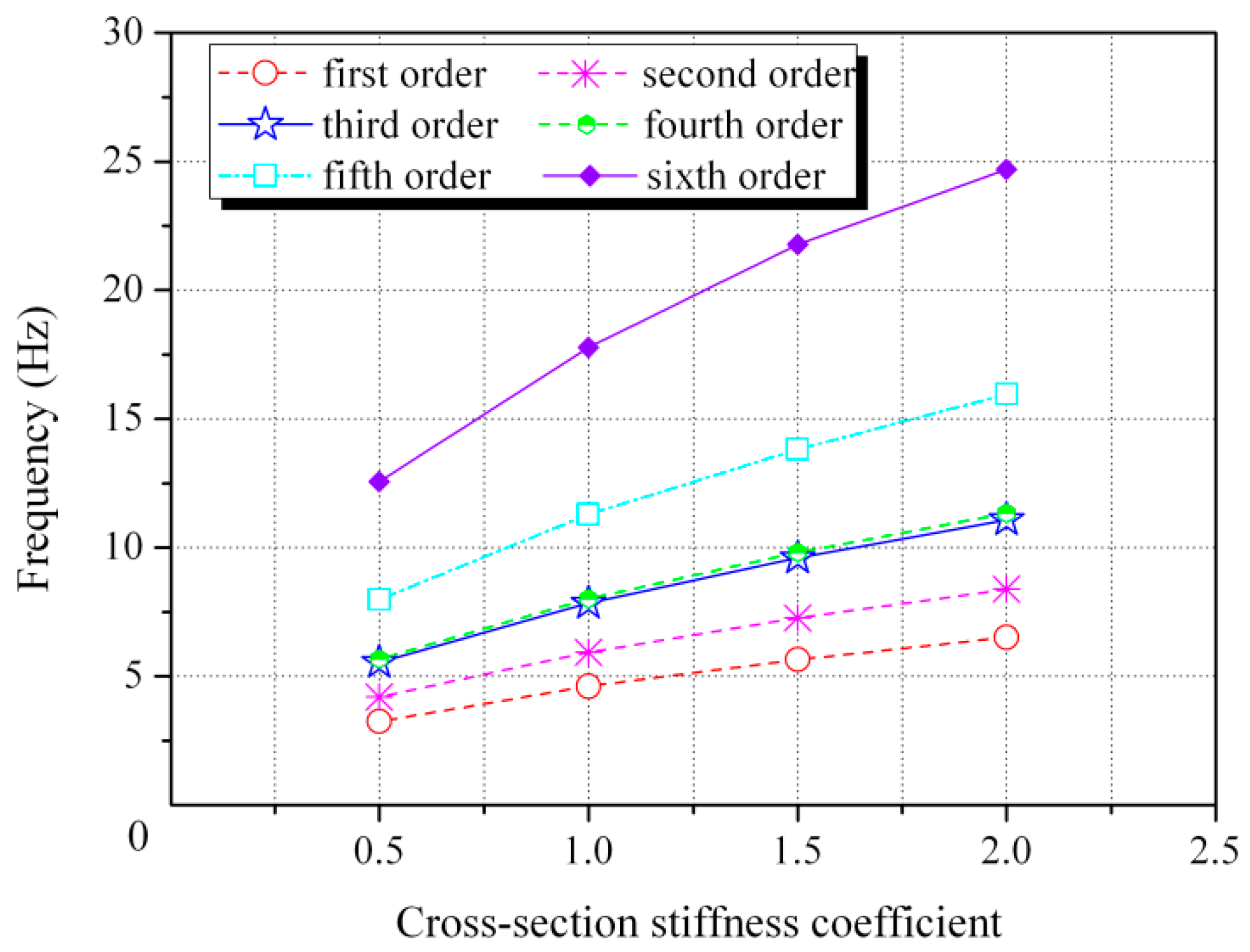
5.3.1. Overall Cross-Section Stiffness

The cross-section dimension of the irregularly-shaped bridge keeps unchanged while the bending moment of inertia changes to 0.5, 1.5, and 2 times that of the original structure. The influence of the cross-section stiffness on the modal characteristics of the irregularly-shaped bridge is shown in Figure 10.
As can be seen from Figure 10, modal frequencies increase with the growth of the cross-section stiffness. The cross-section stiffness has a significant effect on the modal frequencies of the whole structure. The fundamental frequency increases by 41.42% while the stiffness increases to two times the original value. However, the change of stiffness has little effect on mode shapes.

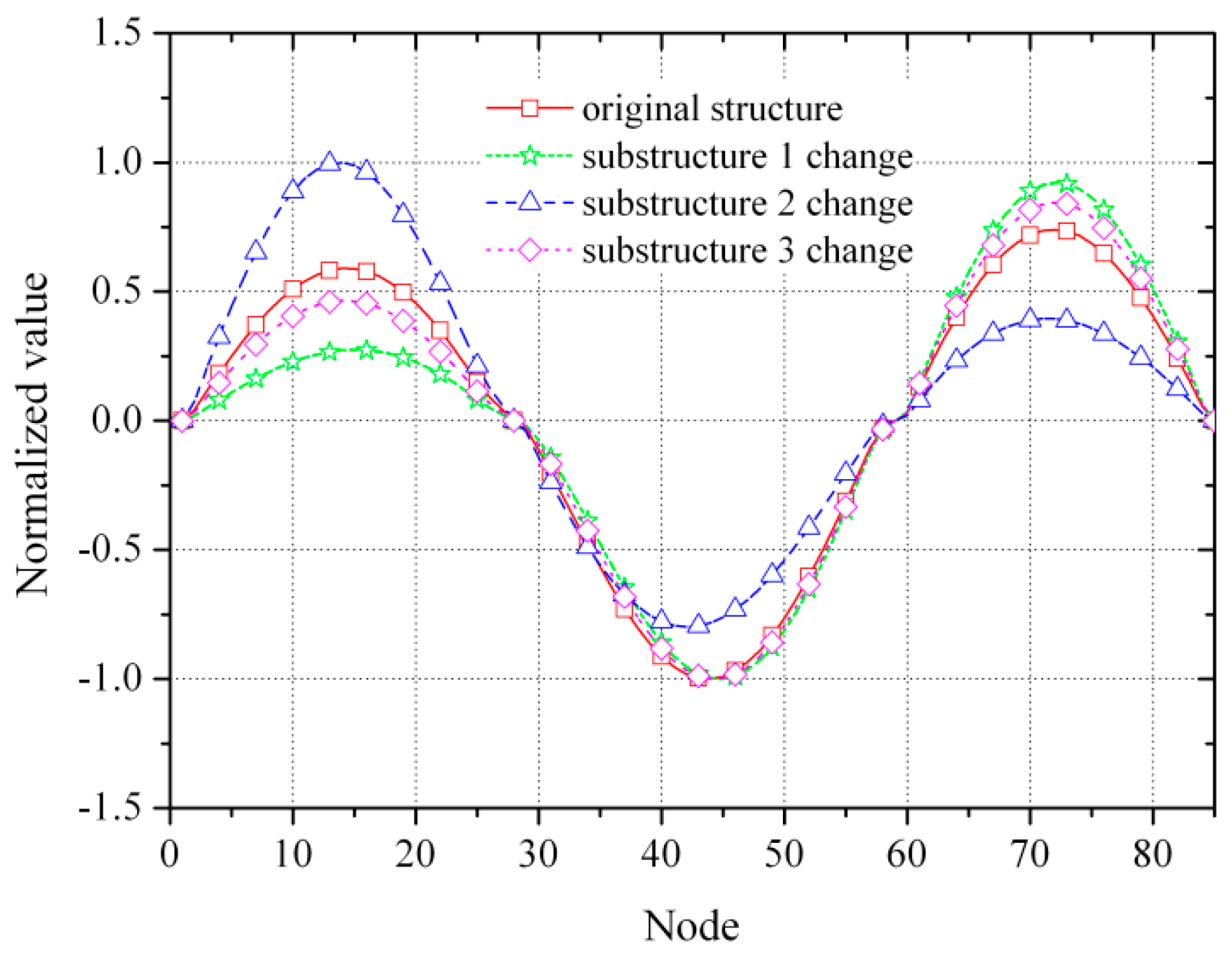
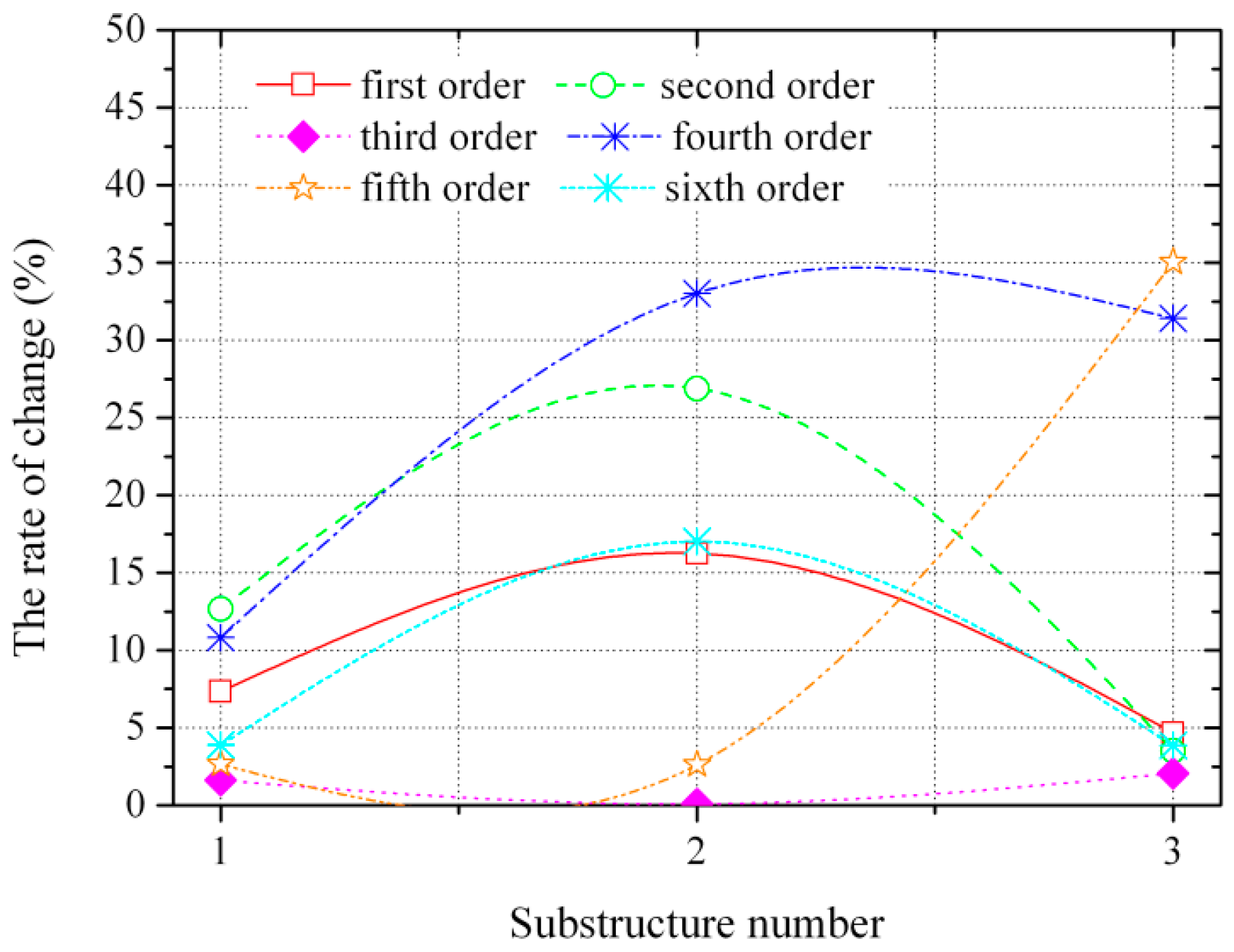
5.3.2. Cross-Section Stiffness of Substructure

The cross-section features of the three substructures are altered, respectively. The bending moment of inertia increases to two times that of the original one to calculate the modal characteristics of the irregularly-shaped bridge. The relationships between the cross-section stiffness of each substructure and the change rates of modal frequencies with respect to that of the original structure are shown in Figure 11.
From Figure 11, we can see that fundamental frequencies increase by 7.35%, 16.25% and 4.58%, when the cross-section stiffness of substructures 1, 2, and 3 is two times that of the original, respectively. The cross-section stiffness of substructure 2 has a greater impact on fundamental frequency. Modal frequencies possess different sensitivities to cross-section stiffnesses. The first, second, and sixth modal frequencies are sensitive to the stiffness change of substructure 2, while the fourth and fifth modal frequencies are sensitive to substructure 3. Therefore, the cross-section stiffnesses of substructures 2 and 3 have significant effects on the modal properties of the whole irregularly-shaped bridge.
The relationships between the cross-section stiffness of the substructures and the first mode shape of the main bridge are shown in Figure 12. Significant change of mode shape has occurred, which indicates that mode shapes have nothing to do with the cross-section stiffness of the whole bridge, but their relative distribution.

5.4. Bearing Conditions

Different bearing conditions listed in Table 4 are determined to discuss their influences on the modal characteristics of the irregularly-shaped bridge. The corresponding results are listed in Table 5.
The modal frequency of the first vertical bending mode and the corresponding mode shapes under different bearing conditions I, II and III are identical. However, the lateral bending modes appear earlier for bearing conditions II and III. It reveals that the lateral restraints under condition II are relatively poorer than under condition I, and their structural stabilities are weak. Therefore, bearing condition I is a more favorable choice for irregular bridge design.

6. Conclusions

In this paper, a novel double coordinate free-interface mode synthesis-based method is proposed for analyzing the modal characteristics of irregularly-shaped bridges. Taking the numerical model of a typical irregularly-shaped structure as an example, the effects of four design parameters including ramp radius, crotch diaphragm stiffness, cross-section features, and bearing condition on modal characteristics are demonstrated and the following conclusions can be drawn.
First, a comparative analysis with the traditional finite element method reveals that the accuracy of the double coordinates free-interface mode synthesis method is favorable and is suitable for analyzing the modal characteristics of irregularly-shaped bridges.
Second, the effect of ramp radius on the modal characteristics of the irregularly-shaped bridge is not obvious. It has a relatively significant effect on modal frequencies such as the third and fifth modes in which ramp vertical bending vibration is the main vibration form. The capability to resist lateral bending of the ramp continues to weaken with the increasing of the ramp radius.
Third, the effect of crotch diaphragm stiffness on modal frequencies and low-order mode shapes is negligible. The changes of crotch diaphragm stiffness can weaken the third and fourth vertical vibration of the irregularly-shaped bridge to a certain extent.
Fourth, the effect of the cross-section stiffness of the whole bridge on modal frequencies is obvious; modal frequencies increase as the stiffness increases. However, this effect is negligible on mode shapes. As for the change of the cross-section stiffness of substructures, substructures 2 and 3 have greater impact on the modal characteristics of the whole bridge. Additionally, the results also indicate that mode shapes have nothing to do with the whole cross-section stiffness but do influence its relative distribution.
Fifth, different bearing conditions will affect structural vibration. Unreasonable conditions can lead to a decrease in the capability to resist lateral bending vibration. The double fixed bearing condition is set at three ends, and the bifurcation position of the bridge can strengthen the lateral bending stiffness, which is more satisfactory.

Acknowledgments

The authors express their appreciation for the financial supports of National Natural Science Foundation of China (No. 51408258, 51378236); China Postdoctoral Science Foundation funded project (2014M560237, 2015T80305); Fundamental Research Funds for the Central Universities (JCKY-QKJC06); Science & Technology Development Program of Jilin Province.

Author Contributions

Hanbing Liu conceived and designed the investigation; Mengsu Zhang performed the calculation and wrote the paper; Xianqiang Wang and Shuai Tian analyzed the data and explained the calculated results; Yubo Jiao edited and audited the content. All authors have read and approved the final manuscript.

Conflicts of Interest

The authors declare no conflict of interest.

References

  1. Lu, P.Z.; Xie, X.; Shao, C.Y. Experimental study and numerical analysis of a composite bridge structure. Constr. Build. Mater. 2012, 30, 695–705. [Google Scholar] [CrossRef]
  2. Sennah, K.M.; Kennedy, J.B. State-of-the-art in design of curved box-girder bridges. J. Bridg. Eng. 2001, 6, 159–167. [Google Scholar] [CrossRef]
  3. Liu, H.; He, X.; Wang, X.; Jiao, Y.; Song, G. An Optimization Algorithm for the Design of an Irregularly-Shaped Bridge Based on the Orthogonal Test and Analytic Hierarchy Process. Algorithms 2016, 9, 74. [Google Scholar] [CrossRef]
  4. Lu, P.Z.; Zhang, J.P.; Zhao, R.D. Analysis and study on model experiment of typical Y-shape bridge. Eng. Mech. 2008, 25, 139–144. [Google Scholar]
  5. Mitra, M.; Gopalakrishnan, S.; Bhat, M.S. A new super convergent thin walled composite beam element for analysis of box beam structures. Int. J. Solids Struct. 2004, 41, 1491–1518. [Google Scholar] [CrossRef]
  6. Ambrosini, R.D.; Riera, J.D.; Danesi, R.F. A modified Vlasov theory for dynamic analysis of thin-walled and variable open section beams. Eng. Struct. 2000, 22, 890–900. [Google Scholar] [CrossRef]
  7. Li, J.; Jin, X.D. Response of flexure–torsion coupled composite thin-walled beams with closed cross-sections to random loads. Mech. Res. Commun. 2005, 32, 25–41. [Google Scholar]
  8. Tabba, M.M.; Turkstra, C.J. Free vibrations of curved box girders. J. Sound Vib. 1977, 54, 501–514. [Google Scholar] [CrossRef]
  9. Kim, N.I.; Kim, M.Y. Exact dynamic stiffness matrix of non-symmetric thin-walled curved beams subjected to initial axial force. J. Sound Vib. 2005, 284, 851–878. [Google Scholar]
  10. Yoon, K.Y.; Park, N.H.; Choi, Y.J.; Kang, Y.J. Natural frequencies of thin-walled curved beams. Finite Elem. Anal. Des. 2006, 42, 1176–1186. [Google Scholar] [CrossRef]
  11. Sapountzakis, E.J.; Mokos, V.G. Dynamic analysis of 3-D beam elements including warping and shear deformation effects. Int. J. Solids Struct. 2006, 43, 6707–6726. [Google Scholar] [CrossRef]
  12. Kong, X.; Wu, D.J.; Cai, C.S.; Liu, Y.Q. New strategy of substructure method to model long-span hybrid cable-stayed bridges under vehicle-induced vibration. Eng. Struct. 2012, 34, 421–435. [Google Scholar] [CrossRef]
  13. Meirovitch, L.; Hale, A.L. On the substructure synthesis method. Am. Inst. Aeronaut. Astronaut. 1981, 9, 940–947. [Google Scholar] [CrossRef]
  14. Biondi, B.; Muscolino, G.; Sofi, A. A substructure approach for the dynamic analysis of train-track-bridge system. Comput. Struct. 2005, 83, 2271–2281. [Google Scholar] [CrossRef]
  15. Li, J.; Law, S.S. Damage identification of a target substructure with moving load excitation. Mech. Syst. Signal Process. 2012, 30, 78–90. [Google Scholar] [CrossRef]
  16. Meirovitch, L.; Hale, A.L. A general dynamic synthesis for structures with discrete substructures. J. Sound Vib. 1982, 85, 445–457. [Google Scholar] [CrossRef]
  17. Richards, T.H.; Leung, A.Y.T. An accurate method in structural vibration analysis. J. Sound Vib. 1977, 55, 363–376. [Google Scholar] [CrossRef]
  18. Leung, A.Y.T. A simple dynamic substructure method. Earthq. Eng. Struct. Dyn. 1988, 16, 827–837. [Google Scholar] [CrossRef]
  19. Hou, S.N. Review of Modal Synthesis Techniques and a New Approach. Shock Vib. Bull. 1969, 4, 25–30. [Google Scholar]
  20. Rubin, S. Improved component-mode representation for substructure dynamic analysis. AIAA J. 1975, 13, 1007–1016. [Google Scholar] [CrossRef]
  21. Craig, R.R.; Bampton, M.C.C. Free-interface methods of substructure coupling for dynamic analysis. AIAA J. 1976, 14, 1633–1635. [Google Scholar] [CrossRef]
  22. Benfield, W.A.; Hrude, R.F. Vibration Analysis of Substructure by Component Mode Substitution. AIAA J. 1971, 9, 1255–1261. [Google Scholar] [CrossRef]
  23. Pinho, R.; Monteiro, R.; Casarotti, C.; Delgado, R. Assessment of continuous span bridges through nonlinear static procedures. Earthq. Spectr. 2009, 25, 143–159. [Google Scholar] [CrossRef]
  24. Monteiro, R.; Delgado, R.; Pinho, R. Probabilistic seismic assessment of RC bridges: Part II—Nonlinear demand prediction. Structures 2016, 5, 274–283. [Google Scholar] [CrossRef]
  25. Monteiro, R. Sampling based numerical seismic assessment of continuous span RC bridges. Eng. Struct. 2016, 118, 407–420. [Google Scholar] [CrossRef]
  26. Clough, R.W.; Penzien, Q.J. Dynamics of Structures; Computers and Structures: Walnut Creek, CA, USA, 2003. [Google Scholar]
Figure 1. Perspective view and collapse of irregularly-shaped bridges. (a) Xiao Xihu overpass in Lanzhou; (b) collapsed overpass in Zhejiang [3].
Algorithms 10 00062 g001
Figure 2. Plan view of the typical irregularly-shaped bridge (unit:m).
Algorithms 10 00062 g002
Figure 3. Cross-sections of the typical irregularly-shaped bridge (unit:m).
Algorithms 10 00062 g003
Figure 4. Bearing positions of the typical irregularly-shaped bridge.
Algorithms 10 00062 g004
Figure 5. Substructure partition of the typical irregularly-shaped bridge model.
Algorithms 10 00062 g005
Figure 6. Change rates of modal frequencies with different ramp radii.
Algorithms 10 00062 g006
Figure 7. Mode shapes of the irregularly-shaped bridge with different ramp radii. (a) Third mode shape (main bridge); (b) Third mode shape (ramp); (c) Fifth mode shape (main bridge); (d) Fifth mode shape (ramp).
Algorithms 10 00062 g007
Figure 8. The first six modal frequencies with different crotch diaphragm stiffness.
Algorithms 10 00062 g008
Figure 9. The third and fourth vertical bending mode shapes with different crotch diaphragm stiffness. (a) Third mode shape (main bridge); (b) Third mode shape (ramp); (c) Fourth mode shape (main bridge); (d) Fourth mode shape (ramp).
Algorithms 10 00062 g009
Figure 10. The first six modal frequencies with different cross-section stiffness.
Algorithms 10 00062 g010
Figure 11. Change rates of the first six modal frequencies with the cross-section stiffness of the substructure.
Algorithms 10 00062 g011
Figure 12. The first mode shape of the main bridge with cross-section stiffness change.
Algorithms 10 00062 g012
Table 1. Bearing conditions of the typical irregularly-shaped bridge.
Bearing PositionsBearing ConditionsBearing PositionsBearing Conditions
C1Double fixed bearingC4Double fixed bearing
C2Double fixed bearingC5Single vertical bearing
C3Single vertical bearingC6Double fixed bearing
Table 2. The first 10 natural frequencies (Hz).
Mode OrderTraditional Finite Element MethodFree-Interface Mode Synthesis MethodRelative Errors (%)
14.6094.6092.389 × 10−7
25.9315.9318.425 × 10−7
36.0436.043−1.542 × 10⁻⁸
47.8377.8374.734 × 10−6
58.0178.0175.827 × 10−6
611.28811.2891.757 × 10−5
711.74911.749−4.183 × 10⁻⁹
817.05717.057−2.392 × 10⁻¹⁰
917.78317.7838.464 × 10−5
1019.52419.524−4.200 × 10⁻¹¹
Table 3. Modal frequencies and vibration shapes of the sixth and seventh modes with different ramp radii (Hz).
ModeRamp Radius (m)
3040506070
611.10111.22811.28910.6169.860
Vertical bendingVertical bendingVertical bendingRamp lateral bendingRamp lateral bending
716.60013.54511.74911.32211.343
Ramp lateral bendingRamp lateral bendingRamp lateral bendingVertical bendingVertical bending
Table 4. Bearing conditions of the irregularly-shaped bridge.
Bearing ConditionBearing Number
C1C2C3C4C5C6
IDouble fixed bearingDouble fixed bearingSingle vertical bearingDouble fixed bearingSingle vertical bearingDouble fixed bearing
IIDouble sliding bearingDouble fixed bearingSingle vertical bearingDouble sliding bearingSingle vertical bearingDouble sliding bearing
IIIDouble fixed bearingDouble sliding bearingSingle vertical bearingDouble fixed bearingSingle vertical bearingDouble fixed bearing
Table 5. Modal frequencies and mode shapes under different bearing conditions (Hz).
Mode OrderBearing Condition
IIIIII
14.609 (vertical bending)1.433 (Lateral bending)4.609 (vertical bending)
25.931 (vertical bending)1.760 (Axial stretching)5.538 (Lateral bending)
36.043 (Lateral bending)4.609 (vertical bending)5.931 (vertical bending)

