Monitoring Cable Tensile Forces of Winch-Assist Harvester and Forwarder Operations in Steep Terrain
by

Franz Holzleitner
1,*, 
Maximilian Kastner
1,
Karl Stampfer
1, 
Norbert Höller
2 and
Christian Kanzian
1 1
Institute of Forest Engineering, Department of Forest and Soil Sciences, University of Natural Resources and Life Sciences, Vienna, Peter-Jordan-Str. 82/3, 1190 Vienna, Austria
2
Corporate Information Services, University of Natural Resources and Life Sciences, Vienna, Peter-Jordan-Str. 82/3, 1190 Vienna, Austria
*
Author to whom correspondence should be addressed.
Forests 2018, 9(2), 53; https://doi.org/10.3390/f9020053
Submission received: 21 December 2017
/
Revised: 18 January 2018
/
Accepted: 22 January 2018
/
Published: 24 January 2018
(This article belongs to the Special Issue Forest Operations, Engineering and Management)
Abstract
:The objective of this case study was to develop and test a specific survey protocol for monitoring tensile forces for winch-assisted harvesters and forwarders with a mounted or integrated constant-pull capstan winch technology. Based on the designed survey protocol, the interactions between work phases, machine inclination, and tensile forces in typical work conditions were analysed. The established workflow, including equipment and the developed analysis routines, worked appropriately and smoothly. The working load on the cable during the study did not exceed 50% of the maximum breaking strength. A maximum tensile force peak at 56 kN was observed during delays for the forwarder, and a peak of 75.5 kN was observed for the harvester, both of which are still within the safe working load when considering a safety factor of two.
Keywords:
winch-assist; harvester; forwarder; tensile force; steep terrain harvesting; cut-to-length1. Introduction
In steep terrain cable yarding combined with motor manual felling is still the most appropriate harvesting system to use [1]. However, winch-assisted harvesting machinery offers new opportunities in terms of cost efficiency and increased safety on steep terrain [2,3]. Reducing soil disturbance by decreased slip on the skid trail can also be achieved [4,5]. Holzleitner et al. [6] stated that machine utilization, as a well-known and major cost driver of expensive harvesting equipment, is not easy to reach. Mounted or integrated cable winches for harvesters or forwarders could offer entrepreneurs new possibilities to increase their portfolio and machine utilization due to providing a wider range of available harvesting operations.
The soil-tire interaction has been described in detail in terms of the interaction of forces and slip while driving on slopes according to different soil types and water content [7,8,9,10]. The maximum trafficable grades without winch assist for different soil conditions have been reported. Furthermore, Wijekoon [11] investigated the soil-tire interaction in terms of number of passes, the ground pressure, and rut depths of forest machines. Wismer and Luth [12] examined the climbing ability of forest machines and their maximum slope. The needed improvements for controlling a cable-towed vehicle to minimize slip control in timber harvesting operations were investigated by Salsbery and Hartsough [13]. Slip control was also one of the main goals in a study on tethered feller bunchers on tracks combined with the maximum gradeability, which ranged from 64% to 85% [14].
The Herzog Forsttechnik AG company was one of the first companies in Central Europe to experiment with winch-assisted forwarders, when in 1999 the company experimented with the prototype of a winch-assisted forwarder called Forcar FC150. Bombosch et al. [15] tested a mounted traction winch on a snow-grooming vehicle to support the driving of a forwarder on steep terrain with a grade of up to 85%. After their successful tests, they stated that a future solution for cost-effective harvesting operations on steep terrain could be a sensor-controlled winch, integrated or mounted on a harvester or forwarder, in order to simultaneously minimize soil compaction. In 2004, Herzog Forsttechnik AG successfully launched the first winch-assisted system for the market [16].
Since then, this technology was developed by entrepreneurs competing for contracts to improve machine utilization and decrease harvesting costs on steep terrain [2]. Regardless, the basic reason for using winch-assisted machinery was not to climb steep terrain; it was mainly invented and designed for supporting driving on soft soils to avoid rutting and to treat sensitive sites with care [16,17]. These results correspond to the assumptions made by Lindroos et al. [18] that existing machines can be adapted to local conditions and that innovation is triggered by the environment of contract competition.
Winch-assisted harvesters and forwarders enable fully mechanized operations on slopes steeper than 30%, which is essentially the limit for operating with ground-based machines depending on their extra equipment, such as chains or bogie tracks [19]. Two different winch-assist concepts are available: the integrated or mounted concept, where the winch is attached to the harvesting machine, or the self-propelled standalone anchoring winch that pulls the harvesting machine. In Central Europe, winch-assisted systems for wheeled or tracked harvesting machinery are mainly based on an integrated capstan or conventional drum winches with cable diameters between 14 and 22 mm. Compared to machinery operating overseas with cable diameters up to 28 mm [20], European equipment is lighter and therefore does not require such large cable dimensions.
Visser et al. [21] monitored tensile forces on winch-assisted machines in New Zealand. Compared to Central European machinery with a wheel-based chassis, the studied machinery in New Zealand had tracks. The authors outlined the importance of on-board monitoring systems for the tensile forces of cables. The use of tensile force monitoring systems for cable yarders goes back to 1988 and was intensified during the 1990s mainly due to safety issues, thereby increasing the lifetime of ropes and improving productivity due to the ability to maximize loads per cycle [22]. Dupire et al. [23] described the importance of knowing the tensile forces in cable yarding operations in order to reduce equipment wear and to decrease operating costs by improving safety.
A lack of detailed knowledge exists about how tensile forces behave in real world conditions. Therefore, it is unclear if current operations are adhering to safety standards. For machine operators and entrepreneurs, awareness about real values is crucial for safer timber harvesting operations, since there is no high resolution on-board information system installed in the cabin to accurately check the actual tensile forces on the cable.
The objective of this study was to develop a scientific approach for monitoring tensile forces for winch-assisted harvesting machinery with mounted or integrated systems. This approach should enable in-depth analysis of tensile forces and their behaviour during real operations with these machines. A specific survey protocol was developed and tested in the field during the case studies. Interactions between work phases, inclination, and tensile forces were analysed in order to determine typical work conditions.
2. Materials and Methods
2.1. Case Studies
The three study sites were located near the villages Gaflenz and Kirchberg/Pielach in Lower Austria and in Kapfenberg in Styria, Austria. Harvesting operations ranged from one study of commercial thinning and two others that were of final fellings after storm damage. The dominating tree species was Norway spruce (Picea abies). All sites had even terrain with an inclination approximately up to 100%. The harvester operated uphill while the forwarder drove empty uphill and then downhill once loaded. All studied operations occurred during daylight conditions on five different days, and both drivers had more than 8000 h operating experience with the machinery in general, which included operation without a winch. The harvester was equipped with track bands on the front bogie axle and chains on the rear axle, whereas the forwarder used track bands on both bogie axles.
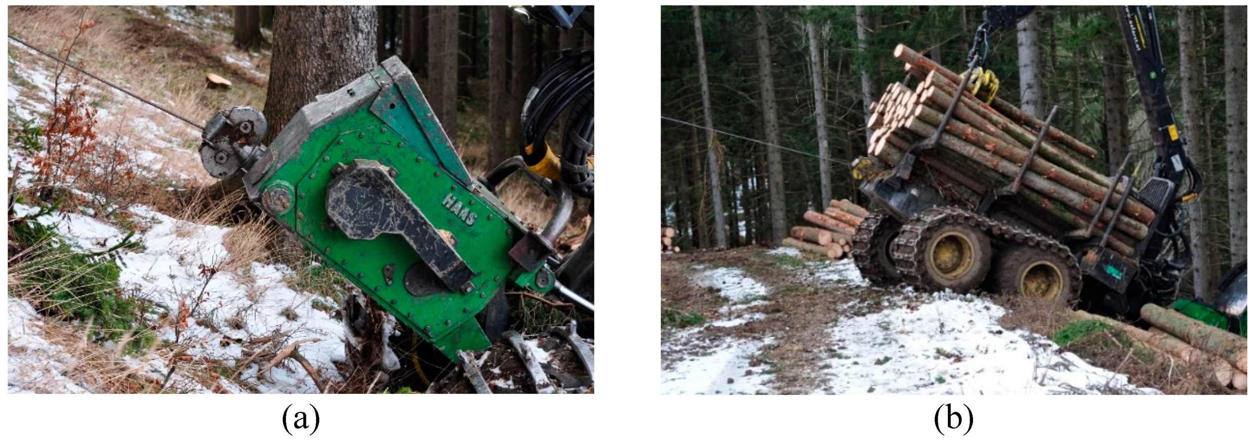
The two observed machines were a John Deere 1170 E harvester, where the winch is mounted in the front of the machine, and a John Deere 1110 E forwarder, with the winch integrated in the mid-section of the frame close to the crane (Figure 1). Both machines were equipped with a winch from the manufacturer Haas Maschinenbau GmbH Germany. Both winches were constant-pull traction winches, using capstan winch technology equipped with a storage drum and a working drum. The pulling force of the winch could be adjusted by the operator within certain limits and could be continuously set up to 9 tonnes. As a special feature, the winch was automatically synchronized with the driving unit independently of the chosen driving direction. With a cable 14 mm in diameter, the drum capacity was up to 500 m. Considering the maximum pulling force of the winch and the maximum breaking force of the cable of 181 kN, a safety factor of two was used. This corresponds to the actual draft version of ISO 19472-2, which is still under revision and not yet published. Both machines were equipped with an additional auxiliary winch holding a synthetic rope to facilitate the rigging process of the steel-made cable.
2.2. Measuring of Tensile Forces and Machine Inclination
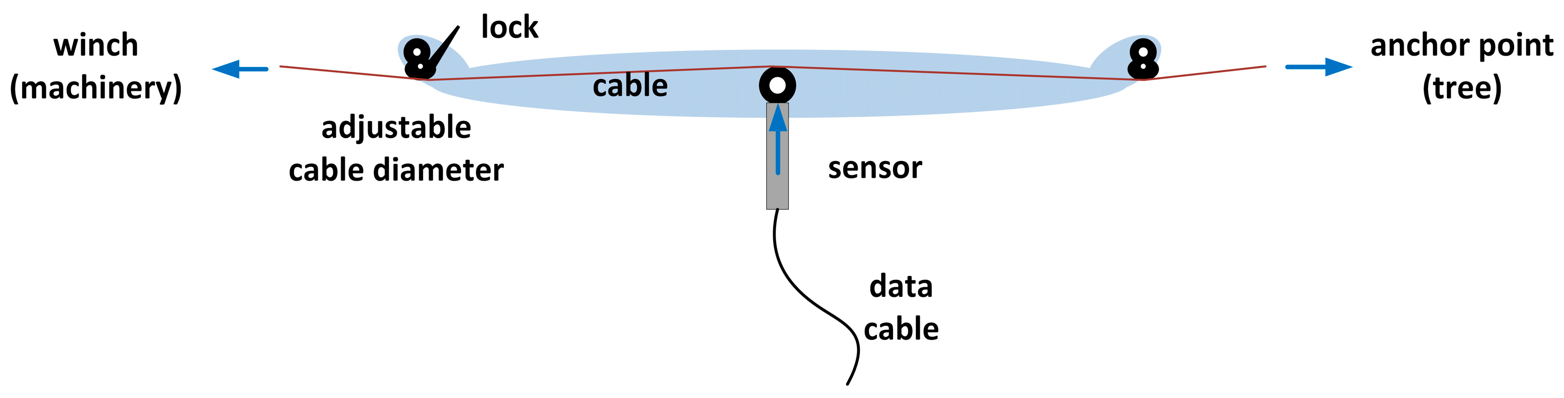
In principle, tensile forces of cables can be directly measured in-line by installing load cells, dynamometers, or sheave pins between the cable and anchor, or indirectly via clamp-on devices using the linear relationship between the deflection in a cable and the resulting force on the central member [24]. During this study, we measured the tensile forces of the cable during operation with the CableBull cable tensile force measurement device from the German manufacturer Honigmann, based on the clamped-on tension monitoring system that measures the resulting forces on the central member for a given deflection (Figure 2).
This device allows online monitoring and recording of tensile forces by clipping it onto the cable on the site while the machinery operates, instead of installing the device between the cable and the machine (Figure 3).
For this study, a toolkit consisting of a Panasonic Toughbook with an extra battery for long-term measurements and data recording was used. In the field, simple data pre-analysis and quick visualization for plausibility checks were completed using the HCCEasy Software from Honigmann GmbH in Wuppertal, Germany. The sample rate for recording can be chosen in the range of 100 to 2000 Hz and was set to 100 Hz for this study. The selected sample rate was chosen according to previous studies [24], and was increased by a factor of 10 to ensure no peaks in tensile forces were missed.
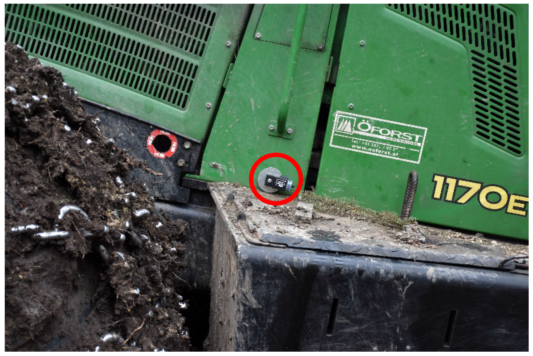
Machine inclination was recorded with the Hobo Pendant G Acceleration Data Logger. The logger uses an internal three-axis accelerometer for measuring the dynamic and static acceleration of gravity in order to record and analyse machine inclination. The sensor was fixed on the rear of the machine’s frame to measure machine inclination during operation (Figure 4). The data were stored on the data logger and read out with the corresponding HOBOware software from ONSET® in Bourne, MA, USA. Exported as a text file, the inclination over time can be used for detailed analysis. The data were transformed from degrees into a percentage after being read out. In this study, the sample rate for recording machine inclination was set to 0.03 Hz due to the data storage space required for long-term recording.
2.3. Recording of Work Phases
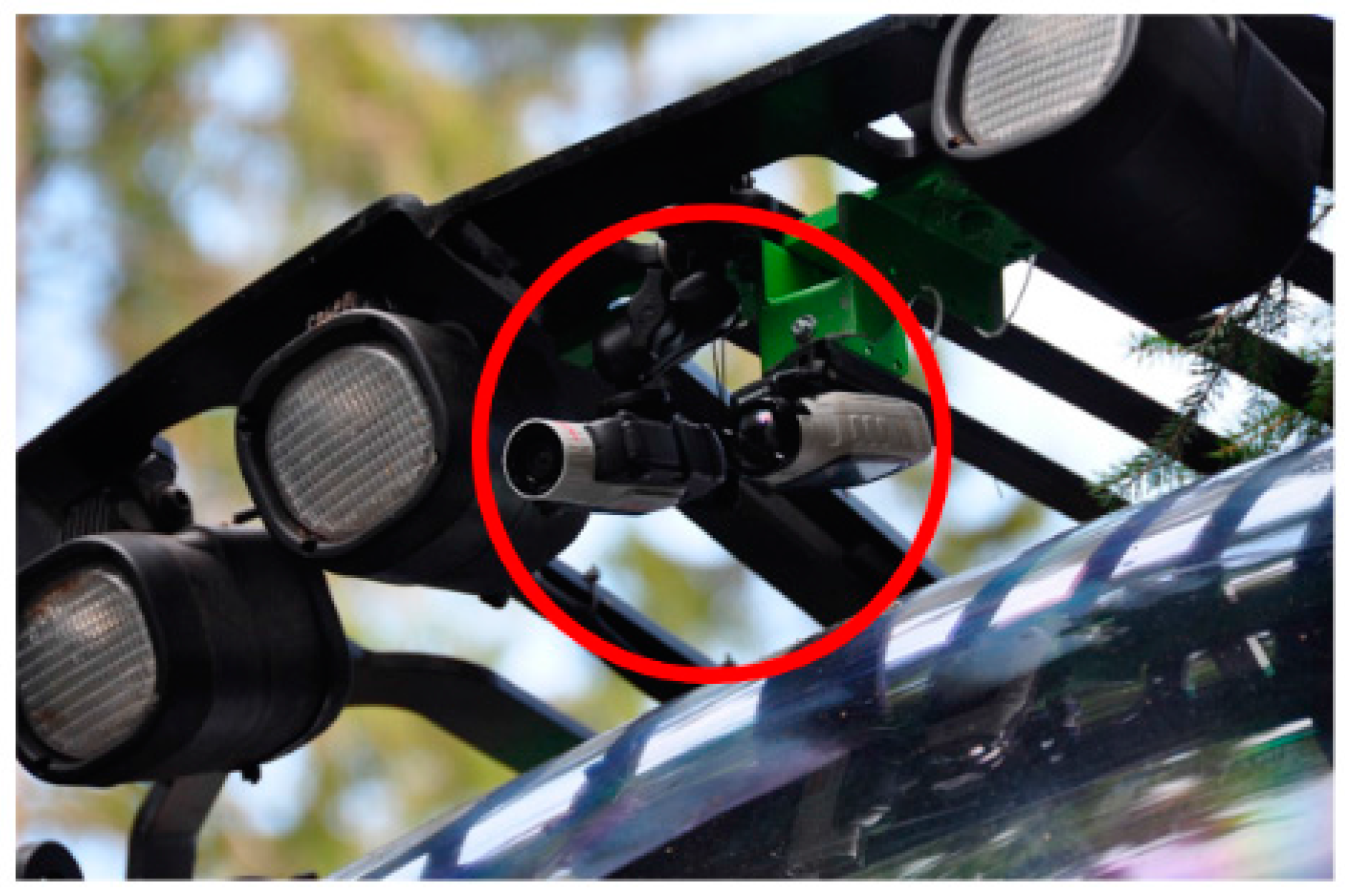
Performing a detailed on-site time and motion study for the work phases was considered organizationally unfeasible and too risky. Therefore, the entire operation was recorded using two on-board video cameras to ensure the data was recorded in case one of the cameras failed, with the video cameras installed above the front windscreen at the protective grating. All videos were captured with 30 frames per second and stored on the memory card. The video capturing data was only limited by the battery life, which was around two hours (depending on the temperature). After the operation was finished, the video data was used to complete time and motion studies post-hoc in the office (Figure 5).
The video data was analysed with a spreadsheet add-on written in Visual Basic for Applications (VBA) using a desktop computer. This add-on for Microsoft Soft Excel was developed by Lauren from LUKE (METLA). Because the add-on offers both options simultaneously, the working time was recorded using both the continuous timing method and the snap back timing method. After the time study was completed, the dataset was exported into an Oracle database table using an R script for further processing.
The tensile force, the inclination measurement equipment, and the video capturing under natural conditions were tested using a first in-field test. Based on this experiment and observations, the working phases were defined. For the harvester, four work phases were determined: (1) felling and processing starts with the fell cut and ends with the full opening of the head with the releasing of the top; (2) other crane work includes all crane work activities that are not related to handling a tree; (3) driving is any movement of the machine no matter if backward or forward; and (4) delays are defined as time not related to effective work.
Following the scheme of the harvester, forwarding activities were divided into seven work phases: (1) loading is when the forwarder starts moving the crane for loading logs onto the bunks without any movement of the machine; (2) unloading was defined by crane work for unloading logs from the bunks without any movement of the machine at the landing; (3) driving empty starts after unloading is finished, including driving to the next loading place, and ends with starting crane work for loading again; (4) driving-loading includes all activities of parallel loading and driving activities; (5) driving loaded starts with stopping crane work for loading and ends by arriving at the landing, ready for unloading; (6) other crane work includes all activities with the crane work not related to loading or unloading; and (7) delays are time not related to effective work.
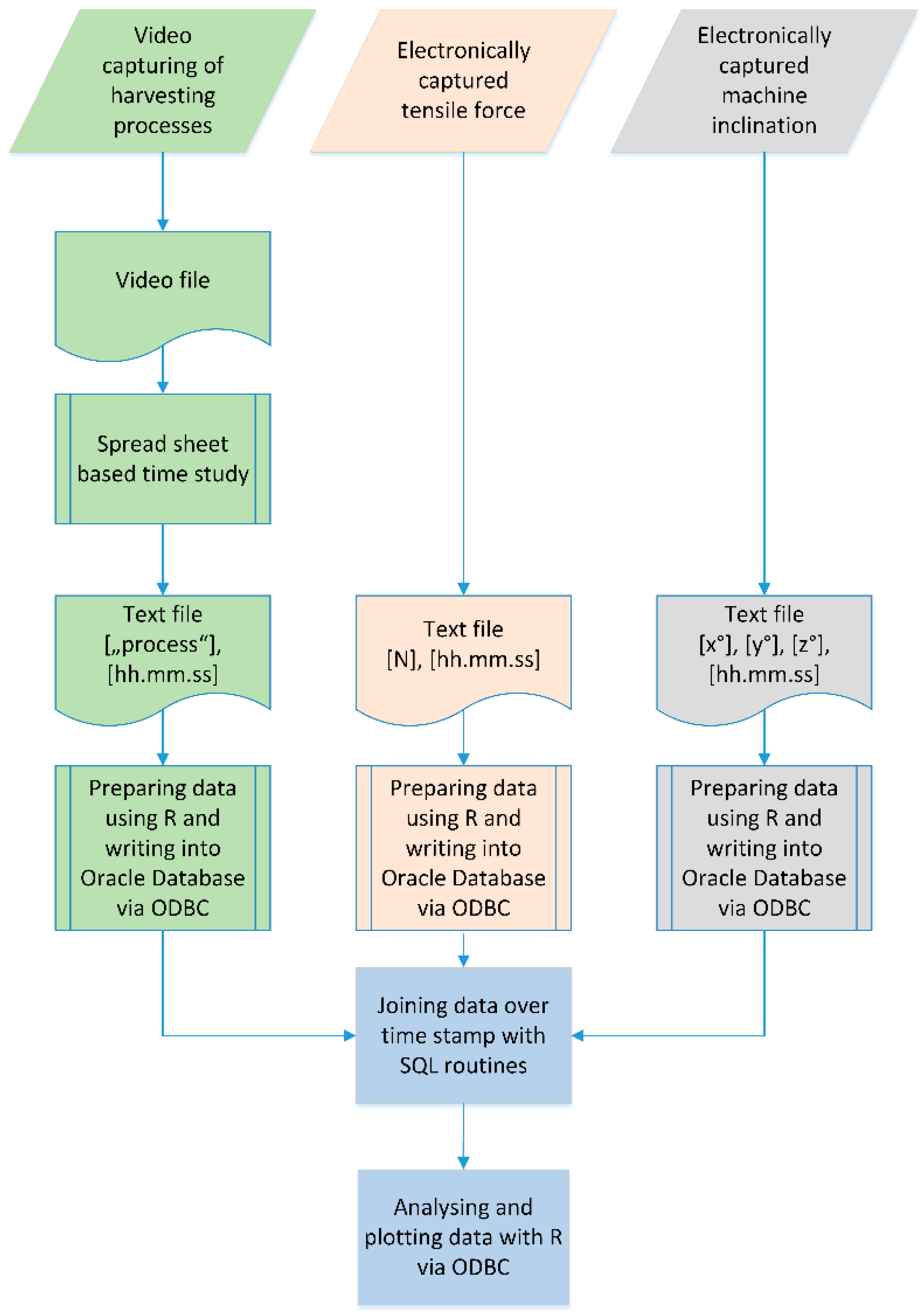
2.4. Workflow Merging and Analysing Recorded Data
Based on precise time stamps from the captured video, the recorded working phases and machine inclination were assigned to the tensile force data by joins using structured query language (SQL) routines. Due to the chronological synchronizing of work phases and inclination with tensile force data, an in-depth analysis of tensile forces based on the current working situation was possible. For this in-depth analysis, a lower sample rate of the tensile force data with 25 Hz was used to reduce computation time. Compression of the tensile force data from 100 to 25 Hz was performed by calculating the mean and maximum values via an R script (Figure 6).
3. Results
3.1. Harvester
Altogether, four hours of harvesting activities including tensile forces were captured, which resulted in 357,475 measurements at the sample rate of 25 Hz. As expected, felling and processing of trees accounted for 41% of the total recorded time, followed by the activities for other crane work and driving. The maximum tensile force once reached a peak of 75.5 kN during felling and processing, which is still below the maximum safe working load of 50% considering the 14-mm diameter of the mounted cable. All activities showed an average in tensile force on the cable above 40 kN, and even close to 50 kN for the whole data set, indicating that the machine was always on steep terrain during operations without any flat sections (Table 1).
The box plots clearly indicate that the pre-set tensile force that is chosen from the driver ranges from 40 to 60 kN and is set and changed constantly by the driver according to the need during operation (Figure 7). Overall, most of the activities used a working cable load of between 20% and 30% (Figure 8).
Compared to the forwarder, harvester activities on the slope did not indicate any cyclic force behaviour. Moreover, a harvester has less cable outhaul and inhaul than a forwarder. The tensile force graph consistently shows higher peaks during every working phase, mostly where the crane is active. This effect can be explained by harvesters handling whole trees after felling and processing (Figure 9).
Unfortunately, the recorded dataset does not include machine inclination for the harvester.
3.2. Forwarder
The entire dataset consisted of 647,277 rows for the forwarder, which was already compressed using a factor of four representing the 25 Hz sample rate. In total, 7.2 h of work were recorded, representing 16 loads. Loading and unloading accounted for 58.5% of the time, and all driving activities consumed 28.4% of the total recorded time.
Mean tensile forces at loading were 97% higher than during the unloading phase at the landing. For all captured cycles, the average working load when driving empty compared to driving loaded had a difference of 12%. Maximum tensile forces were observed during delays with an observed peak of 56 kN, followed by driving empty during loading activities. The observed and captured peak corresponds to a working load of 30.9% of the maximum breaking strength of the cable used (Table 2).
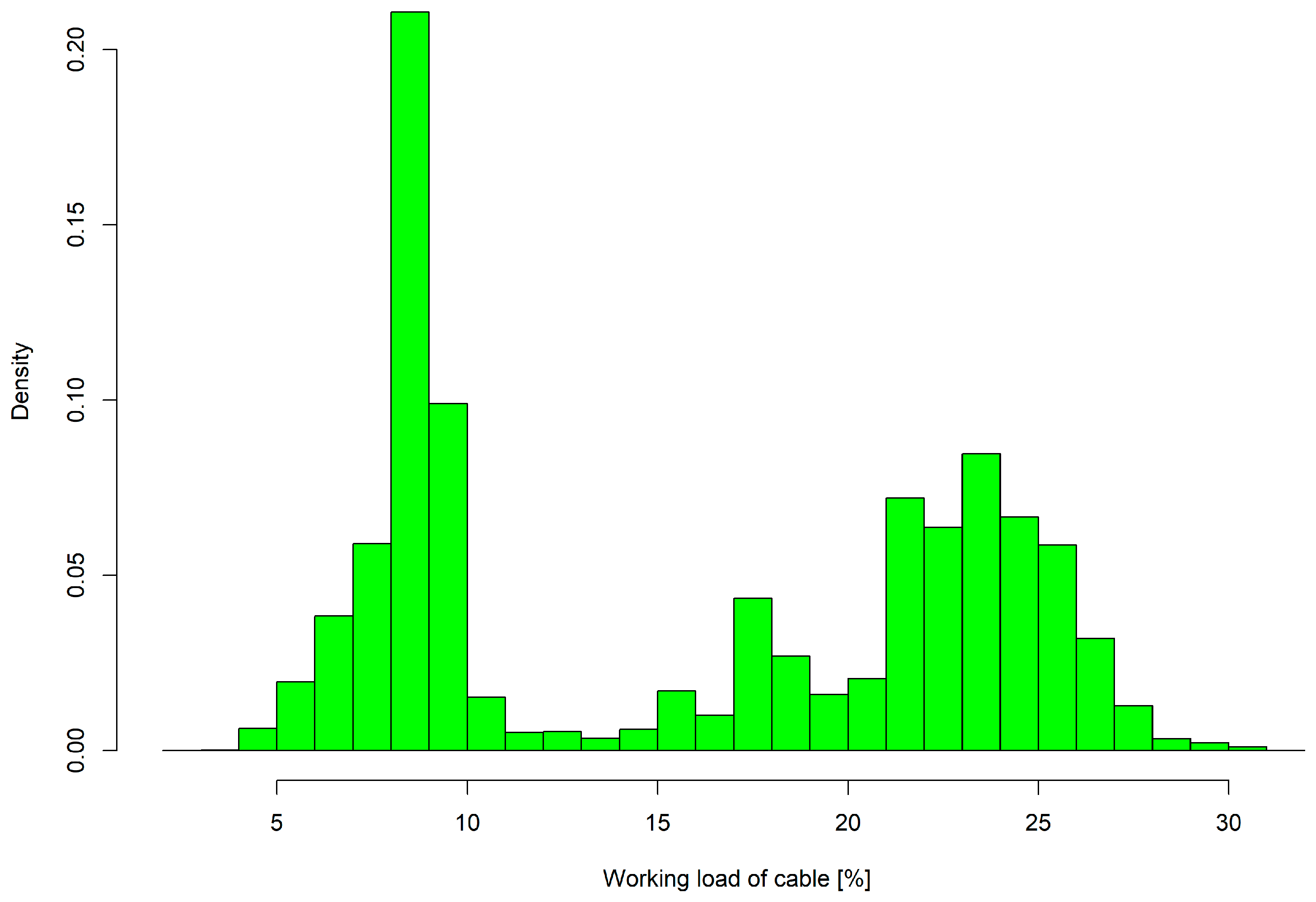
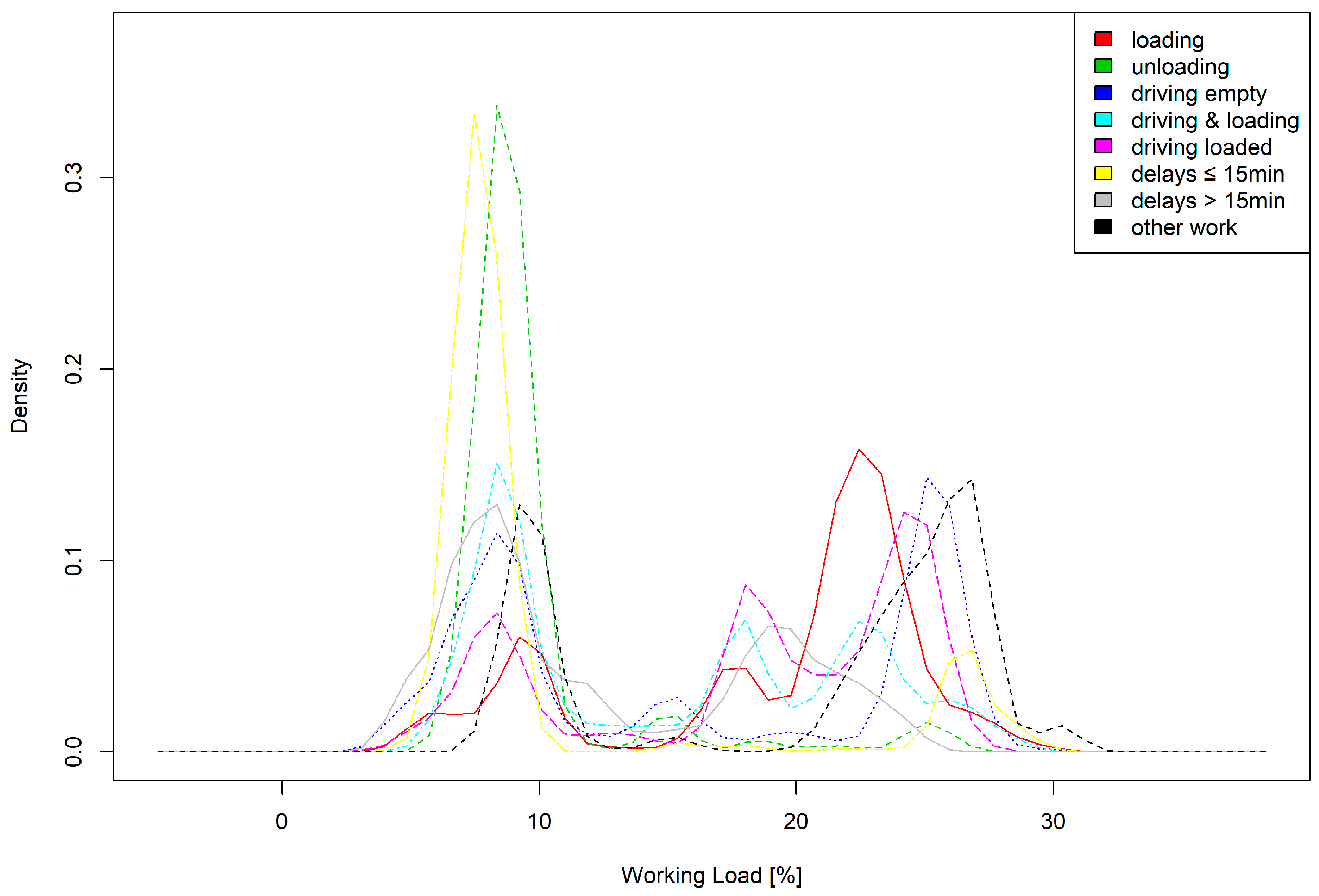
The working load on the cable did not exceed one-third of the maximum breaking strength during the entire study, and was most often between 5% and 11% and 22% and 28%. Analysing the density in terms of the workload based on the defined work phases showed that the majority of low working load was due to delays up to 15 min and the unloading phase. Higher working loads on the cable occurred during loading and driving activities and phases of other work (Figure 10 and Figure 11).
The graph of tensile force over time in Figure 12 shows one forwarder cycle divided into the defined work phases starting at the landing and finishing with unloading and driving empty to the next loading point. The pre-set pulling force from the winch, between 40 and 50 kN, that was chosen by the driver is visible and is three times higher than the tensile force during unloading. During unloading at the landing, the tensile force of the cable was lowered to approximately 20 kN, as chosen by the driver.
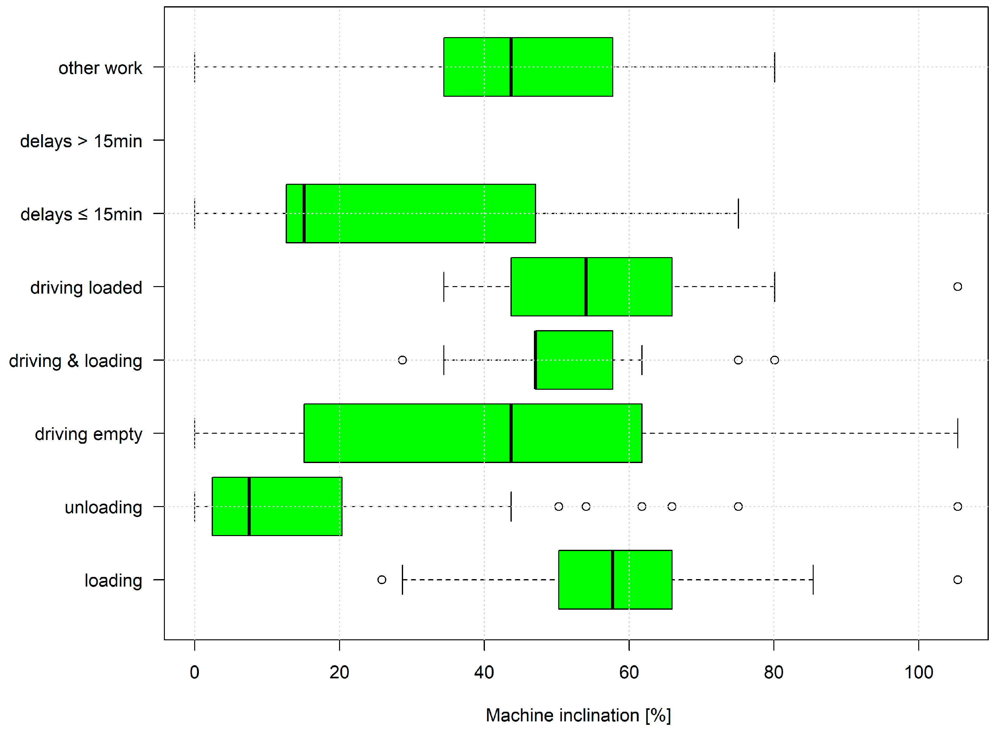
A maximum machine inclination of 105% was reached during loading, unloading, and all driving activities. On average, machine inclination ranged from 40% to 58% for all activities in the stand (Figure 13).
4. Discussion
We present the first detailed tensile force analysis study of winch-assisted fully mechanized harvesting operations in Europe. Based on the developed specific survey protocol interactions between recorded work phases, machine inclination and tensile forces were presented.
Notably, to handle the measuring device for tensile forces with its clamp-on system, if the cable tension were to abruptly release, the measuring device would fall off. This may result in the device being damaged. The purchase cost for the measurement equipment was close to €2900 for the sensor, €900 for the amplifier, and an additional €1500 for the software to check and transfer the data. However, the setup time was negligible due to the easy-to-use clamp-on system, which can be performed during an ongoing operation. Downloading data from the measurement device at the site was not needed, as the tensile force data was stored on a Panasonic Toughbook. This system would not be suitable for moving cables where the winch is anchored at the top of the hill. For such machinery, tensile force sensors, which are built-in shackles, would be an appropriate alternative.
For capturing machine inclination, an inertial measurement unit measuring roll, yaw, and pitch, that is connected to a single-board computer, would facilitate handling and offer additional benefits in terms of long-term data recording with a high sample rate for storage space and power supply. The video capturing of all harvesting activities was highly successful in this study. The data was stored on memory cards that were only changed when the operation or the skid trail was finished. Nevertheless, improvements could be made in terms of directly storing the video stream onto an external storage device and using a permanent power supply to avoid changing batteries every two hours.
The workflow used video to capture the machines’ processes and record the tensile force on the cables, and machine inclination is divided into three subsets of data that was afterward joined using the video time stamps. Future research could combine all sensor data out in the field during data recording. This would reduce the effort required to determine the starting point for analysis. Furthermore, the use of sensors with a high sample rate for detecting activities could lead to semi-automatic recognition of work phases in harvesting operations or support long-term studies [25].
In this study, the winch from the harvester was mounted in the front section. The supplier of this product also offers a rear-mounted solution. This automatically affects the operation mode from uphill to downhill. However, the mounting cannot easily be changed in the forest according to changing conditions and requirements, especially considering the operator’s workspace when it comes to steep terrain, where the levelling of the cabin is not possible and the driver is working downhill. Tensile forces could change due to smoother driving activities compared to when moving uphill with the harvester.
5. Conclusions
The objective of this study was to develop a scientific approach with a robust workflow for the in-depth monitoring and analysing of tensile forces for winch-assisted harvesters and forwarders, based on work phases and machine inclination. The main question was to determine if the machines in use are exceeding the safe working load of the cable being used under real working conditions.
The established workflow, including equipment and the developed analysis routines, worked well. During the study, the working load on the cable did not exceed 50% of the maximum breaking strength. A maximum tensile force peak was observed during delays for the forwarder at 56 kN, and a peak of 75.5 kN for the harvester, which are still within safe working loads, considering a safety factor of two.
Nevertheless, the study only covered a short period of four hours for one harvester and 7.2 h for one forwarder and did not cover a long-term period for different machines, drivers, or various conditions. Therefore, conclusions and findings regarding maximum peaks of tensile forces during harvesting on steep slopes should not be extrapolated to other machines, operators, or harvesting sites. Therefore, further detailed long-term studies are needed to cover different machinery, settings, and modes of operation in combination with productivity. Future studies could focus on the rope wear of this machinery.
Acknowledgments
This publication is a part of the national funded project “Fully mechanized timber harvesting with winch-assisted harvester and forwarder”. The research leading to these results has received funding from the cooperation platform of Forst Holz Papier (FHP). The authors want to thank the entrepreneur Huber and Tazreiter GmbH, including his team, as well as the John Deere Austria partner (ÖFORST) for supporting the study. In addition, we also would like to thank the landowners for enabling the fieldwork. The authors also want to thank the editors and reviewers for their valuable input during the preparation of this original paper.
Author Contributions
Franz Holzleitner and Maximilian Kastner conceived and designed the study layout; Maximilian Kastner performed the field measurements; Franz Holzleitner, Christian Kanzian, and Norbert Höller analysed the data; Franz Holzleitner, Christian Kanzian, and Karl Stampfer wrote the paper.
Conflicts of Interest
The authors declare no conflict of interest.
References
- Heinimann, H.R.; Stampfer, K.; Loschek, J.; Caminada, L. Perspectives on Central European Cable Yarding Systems. Austrian J. For. Sci. 2006, 123, 121–139. [Google Scholar]
- Visser, R.J.M.; Stampfer, K. Expanding ground-based harvesting onto steep terrain: A review. Croat. J. For. Eng. 2015, 36, 321–331. [Google Scholar]
- Axelsson, S.Å. The mechanization of logging operations in Sweden and its effect on occupational safety and health. Int. J. For. Eng. 1998, 9, 25–31. [Google Scholar]
- Hartsough, B.R.; Miles, J.A.; Gaio, C.; Frank, A.A. Cable-towed vehicles for harvesting on mountainous terrain. In Proceedings of the International Mountain Logging and Pacific Northwest Skyline Symposium, Portland, OR, USA, 12–16 December 1988; pp. 54–77. [Google Scholar]
- Wratschko, B. Einsatzmöglichkeiten von Seilforwardern (Application of Cable Forwarders). Master’s Thesis, Institute of Forest Engineering, University of Natural Resources and Life Sciences, Vienna, Vienna, Austria, 2006. [Google Scholar]
- Holzleitner, F.; Stampfer, K.; Visser, R.J.M. Utilization rates and cost factors in timber harvesting based on long-term machine data. Croat. J. For. Eng. 2011, 32, 501–508. [Google Scholar]
- Jacke, H.; Drewes, D. Kräfte, Schlupf und Neigungen—Ein Beitrag zur Terramechanik forstlicher Arbeitsmaschinen. Forces, Slip and Slopes—A Contribution for Terramechanics of Forestal Work Machines. Forst Holz 2004, 50, 259–262. [Google Scholar]
- Hittenbeck, J. Estimation of trafficable grades from traction performance of a forwarder. Croat. J. For. Eng. 2013, 34, 71–81. [Google Scholar]
- Weise, G. Seilgestützter Forstmaschineneinsatz am Hang. Einige Betrachtungen zum Abfangen des Hangabtriebs durch ein Stützseil (Employing winch-assisted forest machines on steep terrain. Some observations to resist downhill-slope force using a cable). Forsttech. Inf. 2004, 9–10, 113–116. [Google Scholar]
- Weise, G. Traktionshilfswinden—Besser am Hang. Forsttech. Inf. 2016, 5, 7–14. [Google Scholar]
- Wijekoon, M. Forest Machine Tire-Soil Interaction. Master’s Thesis, KTH Industrial Engineering and Management, Machine Design, Stockholm, Sweden, 2012. [Google Scholar]
- Wismer, R.D.; Luth, H.J. Off-road traction prediction for wheeled vehicles. J. Terramech. 1973, 10, 49–61. [Google Scholar] [CrossRef]
- Salsbery, B.; Hartsough, B. Control of a cable-towed vehicle to minimize slip. J. Terramech. 1993, 30, 325–335. [Google Scholar] [CrossRef]
- Sessions, J.; Leshchinsky, B.; Chung, W.; Boston, K.; Wimer, J. Theoretical stability and traction of steep slope tethered feller-bunchers. For. Sci. 2017, 63, 192–200. [Google Scholar] [CrossRef]
- Bombosch, F.; Sohns, D.; Nollau, R.; Kanzler, H. Are Forest Operations on steep terrain (average of 70% slope inclination) with wheel-mounted forwarders without slipage possible? In Proceedings of the Austro2003-Symposium: High Tech Forest Operations for Mountainous Terrain, Schlägl, Austria, 5–9 October 2003. [Google Scholar]
- Oberer, F. Symbiose aus Rad und Seil (Symbiosis of wheel and cable). Wald Holz 2012, 1, 28–30. [Google Scholar]
- Wegmann, U. Kletterkünstler Hangforwarder (Climbing artist cable forwarder). Wald Holz 2019, 1, 30–31. [Google Scholar]
- Lindroos, O.; La Hera, P.; Häggström, C. Drivers of advances in mechanized timber harvesting—A selective review of technological innovation. Croat. J. For. Eng. 2017, 38, 243–258. [Google Scholar]
- Heinimann, H.R. Ground-based harvesting systems for steep slopes. In Proceedings of the International Mountain Logging and 10th Pacific Northwest Skyline Symposium, Corvallis, OR, USA, 28 March–1 April 1999; pp. 1–19. [Google Scholar]
- Amishev, D. Winch-Assist Technologies Available to Western Canada; Technical Report No. 37; FPInnovations: Pointe-Claire, QC, Canada, 2016; p. 51. [Google Scholar]
- Visser, R.J.M. Tension Monitoring of a Cable Assisted Machine; Harvesting Technical Note HTN05-11; Future Forests Research Limited: Rotorua, New Zealand, 2013. [Google Scholar]
- Evanson, T. Use of Tension Monitors to Estimate Payload; Harvesting Technical Note HTN01-08; Future Forests Research Limited: Rotorua, New Zealand, 2009. [Google Scholar]
- Dupire, S.; Bourrier, F.; Berger, F. Predicting load path and tensile forces during cable yarding operations on steep terrain. J. For. Res. 2016, 21, 1–14. [Google Scholar] [CrossRef]
- Visser, R.J.M. Tensions Monitoring of Forestry Cable Systems. Ph.D. Thesis, Institute of Forest Engineering, University of Natural Resources and Life Sciences, Vienna, Vienna, Austria, May 1998. [Google Scholar]
- Pierzchała, M.; Kvaal, K.; Stampfer, K.; Talbot, B. Automatic recognition of work phases in cable yarding supported by sensor fusion. Int. J. For. Eng. 2017. [Google Scholar] [CrossRef]
Figure 1.
Observed John Deere 1170 E harvester with a mounted winch in the front (a) and a John Deere 1110 E forwarder with an integrated winch (b).
Figure 1.
Observed John Deere 1170 E harvester with a mounted winch in the front (a) and a John Deere 1110 E forwarder with an integrated winch (b).

Figure 2.
Simplified measuring principle for tensile forces, applied within the used CableBull device.
Figure 2.
Simplified measuring principle for tensile forces, applied within the used CableBull device.

Figure 3.
The CableBull cable tensile force measurement device from the German manufacturer Honigmann based on the clamped-on tension monitoring system (a) and the handheld device for checking tensile forces (b).
Figure 3.
The CableBull cable tensile force measurement device from the German manufacturer Honigmann based on the clamped-on tension monitoring system (a) and the handheld device for checking tensile forces (b).
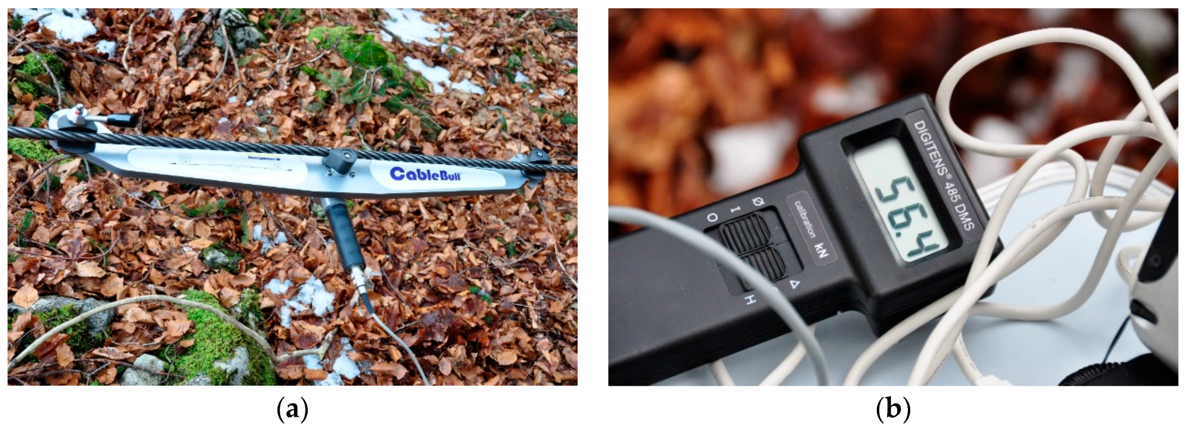
Figure 4.
The location of the mounted acceleration data logger on the rear frame of the machinery.

Figure 5.
Installed video capturing technology at the protective grating above the front windscreen for recording harvesting activities. The second camera ensured data recording in case of failures.
Figure 5.
Installed video capturing technology at the protective grating above the front windscreen for recording harvesting activities. The second camera ensured data recording in case of failures.

Figure 6.
The developed workflow for preparing data from the time study, the tensile force measurements, and from the sensor recording machine inclination for writing via an Open Database Connectivity (ODBC) into the database and joined using the time stamps for further analysis. SQL: structured query language.

Figure 7.
Tensile forces divided into defined work phases of the observed harvester for all captured data. Each box plot contains whiskers including data from 2.5% to 97.5%, boxes from 25% to 75%, and the black line denotes the median. Outliers are marked as points.
Figure 7.
Tensile forces divided into defined work phases of the observed harvester for all captured data. Each box plot contains whiskers including data from 2.5% to 97.5%, boxes from 25% to 75%, and the black line denotes the median. Outliers are marked as points.

Figure 8.
Working load of the cable used during harvesting activities for all captured data.
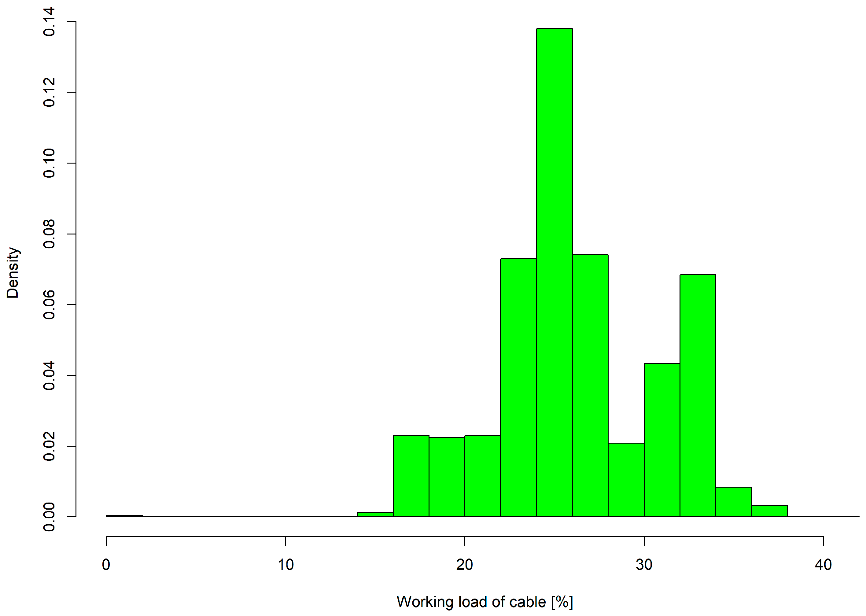
Figure 9.
Tensile force graph showing the defined work phases of the observed harvester for a selected time period.
Figure 9.
Tensile force graph showing the defined work phases of the observed harvester for a selected time period.
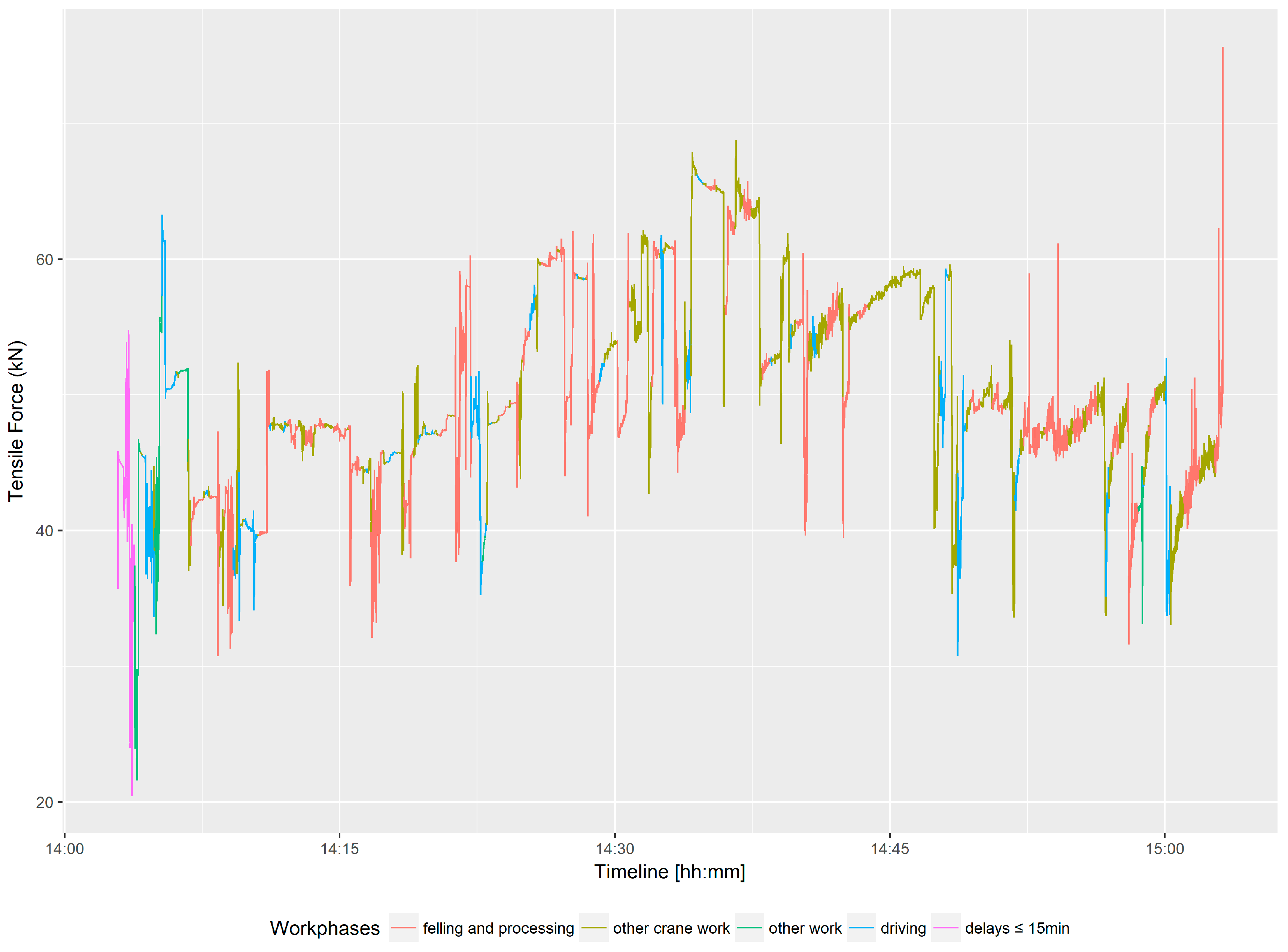
Figure 10.
Working load of cable used during forwarding activities for all captured data.

Figure 11.
Working load for the cable used during forwarding activities divided into the defined work phases.
Figure 11.
Working load for the cable used during forwarding activities divided into the defined work phases.

Figure 12.
Tensile force graph showing one cycle of the observed forwarder over time with the assigned working phases.
Figure 12.
Tensile force graph showing one cycle of the observed forwarder over time with the assigned working phases.
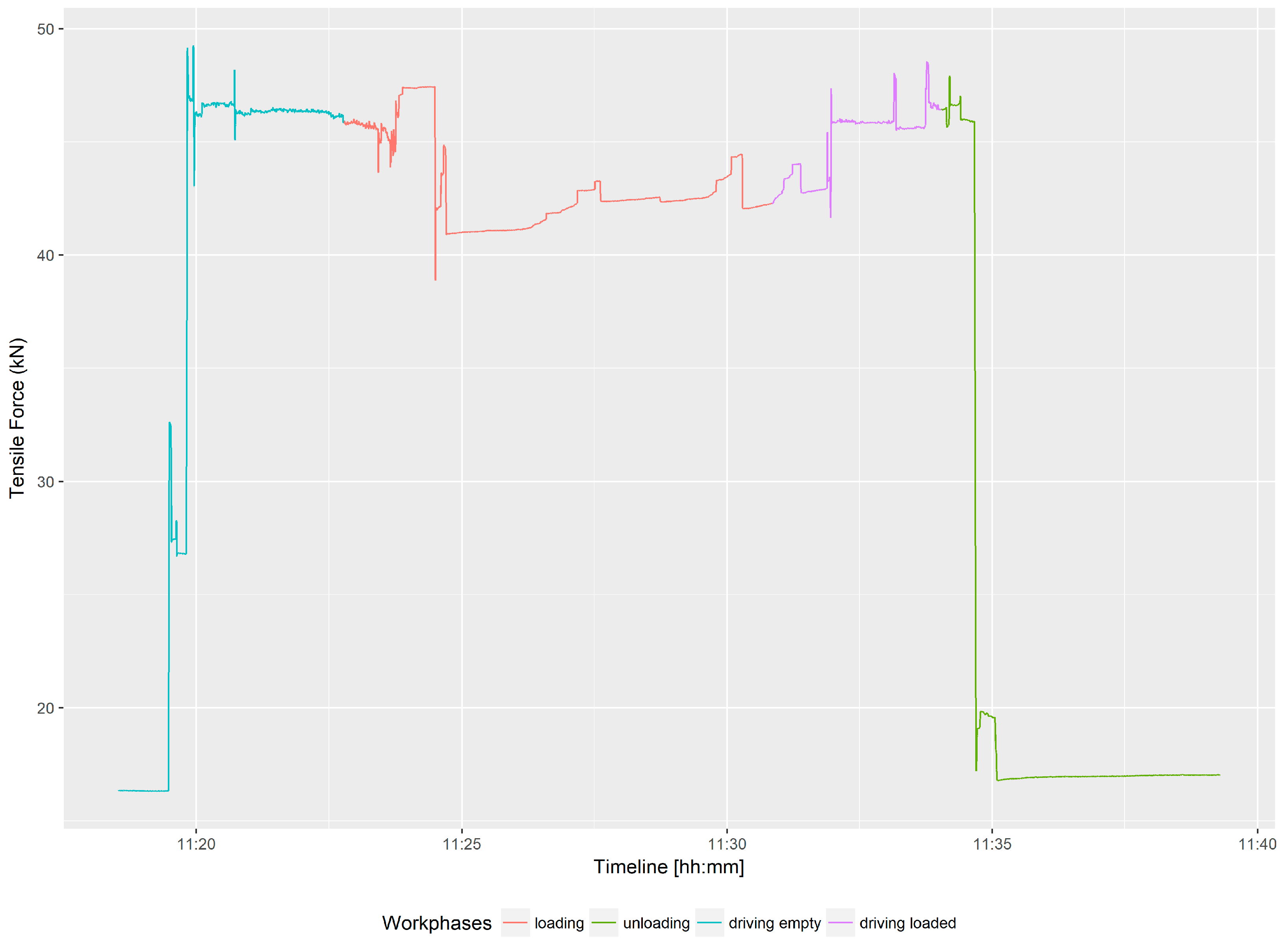
Figure 13.
The recorded machine inclination for the forwarder during the study for a selected time period. Each box plot contains whiskers including data from 2.5% to 97.5%, boxes from 25% to 75%, and the black line denotes the median. Outliers are marked as points.
Figure 13.
The recorded machine inclination for the forwarder during the study for a selected time period. Each box plot contains whiskers including data from 2.5% to 97.5%, boxes from 25% to 75%, and the black line denotes the median. Outliers are marked as points.

Table 1.
Descriptive statistics for the recorded tensile forces in Newton (N) at the harvester divided into defined work phases.
Table 1.
Descriptive statistics for the recorded tensile forces in Newton (N) at the harvester divided into defined work phases.
| Work Phase | Minimum | First Quartile | Median | Mean | Third Quartile | Maximum | Records |
|---|---|---|---|---|---|---|---|
| Felling and processing | 12 | 43,140 | 46,553 | 47,797 | 53,517 | 75,647 | 146,250 |
| Other crane work | 359 | 43,943 | 47,930 | 49,501 | 57,373 | 68,779 | 100,627 |
| Other work | 21,603 | 39,308 | 45,838 | 44,763 | 51,792 | 60,103 | 2654 |
| Driving | 28,525 | 41,248 | 44,440 | 44,169 | 47,014 | 66,210 | 60,345 |
| Delays ≤15 min | 9083 | 38,810 | 45,194 | 45,817 | 55,990 | 68,001 | 37,236 |
| Delays >15 min | 29,363 | 44,224 | 44,793 | 44,524 | 45,281 | 55,139 | 10,363 |
Table 2.
Descriptive statistics for the recorded tensile forces of the forwarder in Newton (N) divided into defined work phases.
Table 2.
Descriptive statistics for the recorded tensile forces of the forwarder in Newton (N) divided into defined work phases.
| Work Phase | Minimum | First Quartile | Median | Mean | Third Quartile | Maximum | Records |
|---|---|---|---|---|---|---|---|
| Loading | 7137 | 31,159 | 39,260 | 34,642 | 41,931 | 54,708 | 240,781 |
| Unloading | 7538 | 14,957 | 15,807 | 17,563 | 16,969 | 49,517 | 137,668 |
| Driving empty | 5479 | 15,023 | 27,327 | 29,552 | 45,655 | 55,630 | 96,429 |
| Driving and loading | 7880 | 15,562 | 26,962 | 27,369 | 39,597 | 52,637 | 15,628 |
| Driving loaded | 4239 | 22,018 | 35,847 | 33,118 | 43,871 | 53,445 | 87,246 |
| Delays ≤15 min | 8742 | 12,927 | 14,508 | 19,148 | 14,562 | 56,259 | 39,559 |
| Delays >15 min | 8640 | 13,831 | 17,448 | 22,854 | 34,608 | 45,428 | 11,431 |
| Other work | 15,490 | 17,544 | 43,350 | 36,524 | 48,463 | 55,032 | 18,535 |
© 2018 by the authors. Licensee MDPI, Basel, Switzerland. This article is an open access article distributed under the terms and conditions of the Creative Commons Attribution (CC BY) license (http://creativecommons.org/licenses/by/4.0/).
Share and Cite
MDPI and ACS Style
Holzleitner, F.; Kastner, M.; Stampfer, K.; Höller, N.; Kanzian, C. Monitoring Cable Tensile Forces of Winch-Assist Harvester and Forwarder Operations in Steep Terrain. Forests 2018, 9, 53. https://doi.org/10.3390/f9020053
AMA Style
Holzleitner F, Kastner M, Stampfer K, Höller N, Kanzian C. Monitoring Cable Tensile Forces of Winch-Assist Harvester and Forwarder Operations in Steep Terrain. Forests. 2018; 9(2):53. https://doi.org/10.3390/f9020053
Chicago/Turabian StyleHolzleitner, Franz, Maximilian Kastner, Karl Stampfer, Norbert Höller, and Christian Kanzian. 2018. "Monitoring Cable Tensile Forces of Winch-Assist Harvester and Forwarder Operations in Steep Terrain" Forests 9, no. 2: 53. https://doi.org/10.3390/f9020053
Note that from the first issue of 2016, this journal uses article numbers instead of page numbers. See further details here.