Secure Inter-Frame Space Communications for Wireless LANs

Department of Convergence Security Engineering, Sungshin University, 02844 Seoul, Korea
Future Internet 2018, 10(6), 47; https://doi.org/10.3390/fi10060047
Submission received: 19 April 2018
/
Revised: 1 June 2018
/
Accepted: 3 June 2018
/
Published: 4 June 2018
Abstract
:The internet of things (IoTs) offers a wide range of consumer benefits, from personal portable devices to internet-connected infrastructure. The wireless local area network (WLAN) is one of the potential candidates for IoTs technology to connect billions of smart devices. Long-range WLAN is widely deployed in dense networks as an alternative to cellular networks or satellite internet access because of its low cost, high performance, and existing ecosystem. However, due to the nature of unregulated communications in industrial, scientific, and medical (ISM) bands, WLANs experience interferences from other radios such as radars and frequency hopping devices. Once interference is detected at a WLAN device, the channel is avoided and other channels become crowded. Thus, it degrades network throughput and channel utilization. In this paper, a secure inter-frame space communication system design is proposed for WLANs to share the ISM bands with other radio systems that generate periodic radio signals. The proposed secure inter-frame communication scheme achieves the goal by designing accurate radar detection and secure inter-frame space communication. The simulation results demonstrate that the proposed scheme significantly increases the receiver sensitivity and user datagram protocol throughput.
1. Introduction
Wireless local area networks (WLANs) such as IEEE 802.11b/g were initially deployed in 2.4-GHz bands, in which industrial, scientific, and medical (ISM) devices are allowed to operate [1]. As WLANs were deployed widely and became an essential feature of everyday life, more spectrum was required because the 2.4-GHz band has only three channels. Thus, WLANs were extended to operate in the 5-GHz (IEEE 802.11a/n/ac/ax) and Sub-1-GHz (IEEE 802.11af/ah) ISM bands, which are also used by many other radio systems such as cordless phones, DECT (Digital Enhanced Cordless Telecommunications), and radars [2]. Because of their dependence on the same channel frequencies, the possibility of interference is higher.
Several studies have investigated the interference effect, and several approaches to using new protection mechanisms in WLAN systems have been reported [3,4,5,6]. However, their scope was confined to demonstrating deteriorated performance due to interference for WLANs, and coexistence by channel avoidance as a passive way [3,4]. Some of the new protection mechanisms require modification of the current standard [5,6]. To protect the channel medium in the current WLAN standards, WLANs basically operate in the manner of carrier detection and avoidance. For the carrier detection and avoidance operation, spectrum-sharing mechanisms, such as dynamic frequency selection (DFS) and transmit power control (TPC), are required for WLANs [7,8]. Dynamic frequency selection and TPC allow WLANs to share channels with various radio systems, which are operating on the 5-GHz ISM channel frequencies. However, these conservative channel-access mechanisms are not efficient in terms of channel utilization and network throughput.
In IEEE 802.11ac and IEEE 802.11ax standards, WLANs support 80-MHz and 160-MHz bandwidth operations [9,10]. Although IEEE 802.11ac/ax can adjust the bandwidth dynamically using pre-defined protocols between the transmitter and receiver, these wide-bandwidth modes may not work in the real world because they are operated in an “all-or-nothing” mode against non-802.11 interferences. In other words, WLANs may fail to communicate in the wide bandwidth if the channel is affected by other radios’ interferences. For example, in the 5-GHz radar bands, WLANs should not cause interference in the radar systems. The International Telecommunication Union (ITU) Recommendation on DFS provides test patterns and threshold criteria to test DFS implementations [8]. According to the standards in WLANs and ITU Recommendation, a DFS system should meet all the test criteria, and the system should avoid the radar channel automatically. However, it is not an efficient way of communication because WLANs and radar systems can share the frequency spectrum if WLANs detect radar more accurately and transmit data frames in idle time for the shared channel. As another example, frequency hopping radios are widely used in ISM bands because of their robustness, long range, and low cost. However, if a frequency hopping radio and a WLAN device exist in the same channel, the frequency hopping signal prevents WLANs from communicating in the channel. Eventually, the WLAN devices should change the channel. Since the radar systems and frequency hopping radios can be adopted for many purposes in the modern wireless systems, secure inter-frame space communication is required to improve channel utilization and network throughput.
Radars were used for decades before the same frequency bands were included in 5-GHz ISM bands that were allocated for unlicensed use. Since frequency resources have become more valuable, frequency spectrum sharing has become indispensable. The ISM bands have been adopted by many local access specifications. Radar systems emit very strong pulse signal arrays that interfere with the network communication packet signals. This scenario is less threatening than the opposite case, since WLAN communication packets are retransmitted if they are not successfully received. A serious problem occurs in the opposite direction, that is, the WLAN’s packet signals interfere with radar operation. Although the WLAN’s signal is usually low-powered and limited within a small range, the radar detector is designed to detect a very small signal reflected by objects located far away from the radar transmitter. If a WLAN or a corresponding 5-GHz transmitter system works near a radar system, the operation of the radar system will be vulnerable and it can cause a serious information error. Radar systems are used for weather measurement, military information, etc. The false alarm of the radar system may cause much more serious problems than at WLAN communications.
To avoid radar malfunction or false alarm, WLAN societies have developed a technique called dynamic frequency selection (DFS) to avoid using the radar-occupied frequency bands. Dynamic frequency selection is meaningful since radar systems usually use narrow frequency bands. Wireless local area network systems use wider frequency bands of 20 MHz or 40 MHz compared to radar systems. If a WLAN system detects a radar pulse signal, it leaves the frequency bands for another clear frequency band, just as it leaves a frequency band when the frequency band is too noisy. At the beginning of the WLAN operation, an access point (AP) can search the best channel or frequency band and can detect and avoid the frequency band that a radar system occupies. The term DFS has been used for avoiding the radar-occupied frequency bands.
The DFS operation includes radar signal detection, decision, and frequency band change. The radar signal detection should be made in the physical layer (PHY), while decision and frequency change occur in the medium access control (MAC) layer. The radar signal detection tries to detect aspects of radar signals, such as the pulse width, frequency band, and pulse period, which represent radar signals well. In general, radar signals have many different types and parameters. It can be complicated for the signal detector to match all types of radar signals. The most popular method to detect radar signals is to measure the power of the received signal.
Once the radar signal power is measured, the WLAN transceivers find and match the pulse width, pulse period, etc. Since the periods of the radar pulses are relatively long, this match process usually belongs to the MAC layer instead of the PHY. The normal period of radar pulse signals is wider than the WLAN packet lengths. The frequency change is also among the main functions of the MAC layer.
2. Periodic Interference Detection Techniques
Periodic interference detection depends on what characteristics of the interference are to be detected. Periodic interferences vary in carrier frequency, pulse period, staggered pulse repetition frequency (PRF), etc. One or a combination of these characteristics can be used to determine the interference. The difficult part is that the designed periodic-interference detection algorithm should detect as many periodic interferences as possible, throughout the world. This generality is difficult to achieve since not all the radios’ information is open to the public.
2.1. Detection of Carrier Frequency and Bandwidth
If the carrier frequency is to be measured to determine a periodic interference, the assumed interference’s carrier frequencies must be known. If the received signal resides within a narrow frequency band centered around an assumed carrier frequency, the incoming signal may be determined as the assumed interference. This method needs to know all the interferences’ frequencies and their spectral band characteristics, or this information should be adaptively given according to the places near the known radio system. Many radio systems do not reveal which frequency they use and how it is used. This method needs a vast list of radio signal frequencies and bandwidth, and tries to analyze and match the frequency of the pulses [11]. It is also difficult to measure the tone frequency since the pulse width is short. With 20-MHz sampling, a pulse width of 1 µs provides only 20 samples.
2.2. Periodicity of Pulse or PRF
Most of the radar pulses and frequency hopping signals have periodicity with either constant period or staggered period with two or more periods. If a radio system uses random periods between pulses, the interference detector cannot use this characteristic. A constant period or PRF requires the simplest detection algorithm that searches the periodic appearance of power. This approach is the easiest to develop, since radar signals have a simple periodicity scheme thus far [12].
2.3. Signal Power and Pulse Width
It is common to measure the power of the received signal and compare it with a threshold to determine if a signal exists. In addition to this, if pulse width is considered, most radar pulses are very short compared with WLAN frames. For example, many weather radar systems use 1-µs or even shorter pulses. If a power above a power threshold appears for less than a time threshold, it can be a radar pulse [13].
This approach needs fine tuning to decrease the false alarm probability. A large power signal can appear through other sources instead of the target periodic interference. Although an impulse noise may exceed a power threshold, it should not be determined as a periodic interference signal. One method of fine tuning is to match the received power with the known pulse power characteristics, such as constant power and abrupt appearance and disappearance, as well as short width. It should be noted that some radar signal pulses have a pulse width of over 100 µs. In this case, it is difficult to find an appropriate period threshold for the “short” pulse.
3. Secure Inter-Frame Space Communication
3.1. Periodic Interference Detection
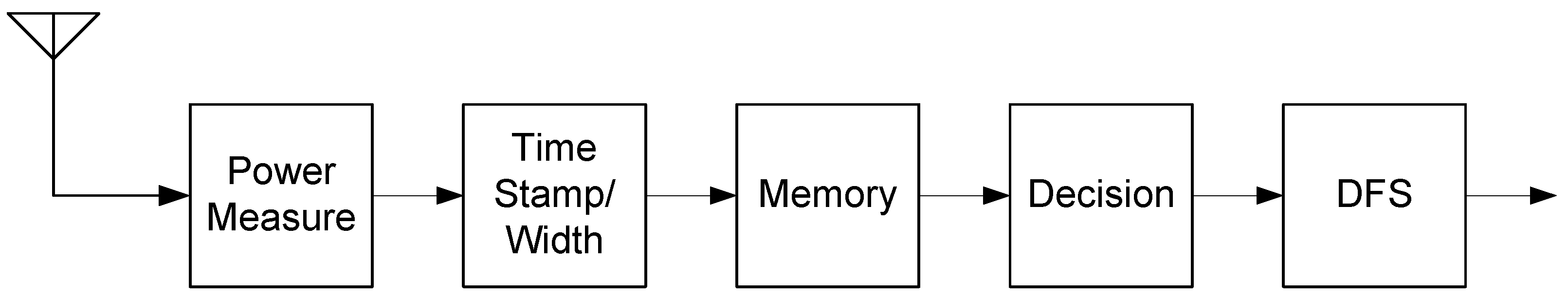
The implemented periodic interference detection method is based on the signal power and pulse periodicity. Thus far, this periodic property of radar systems has been simple and clear for most cases. This means that some simple periodic detection algorithm can perform well for most radar cases. Figure 1 shows the block diagram of the DFS algorithm implemented.
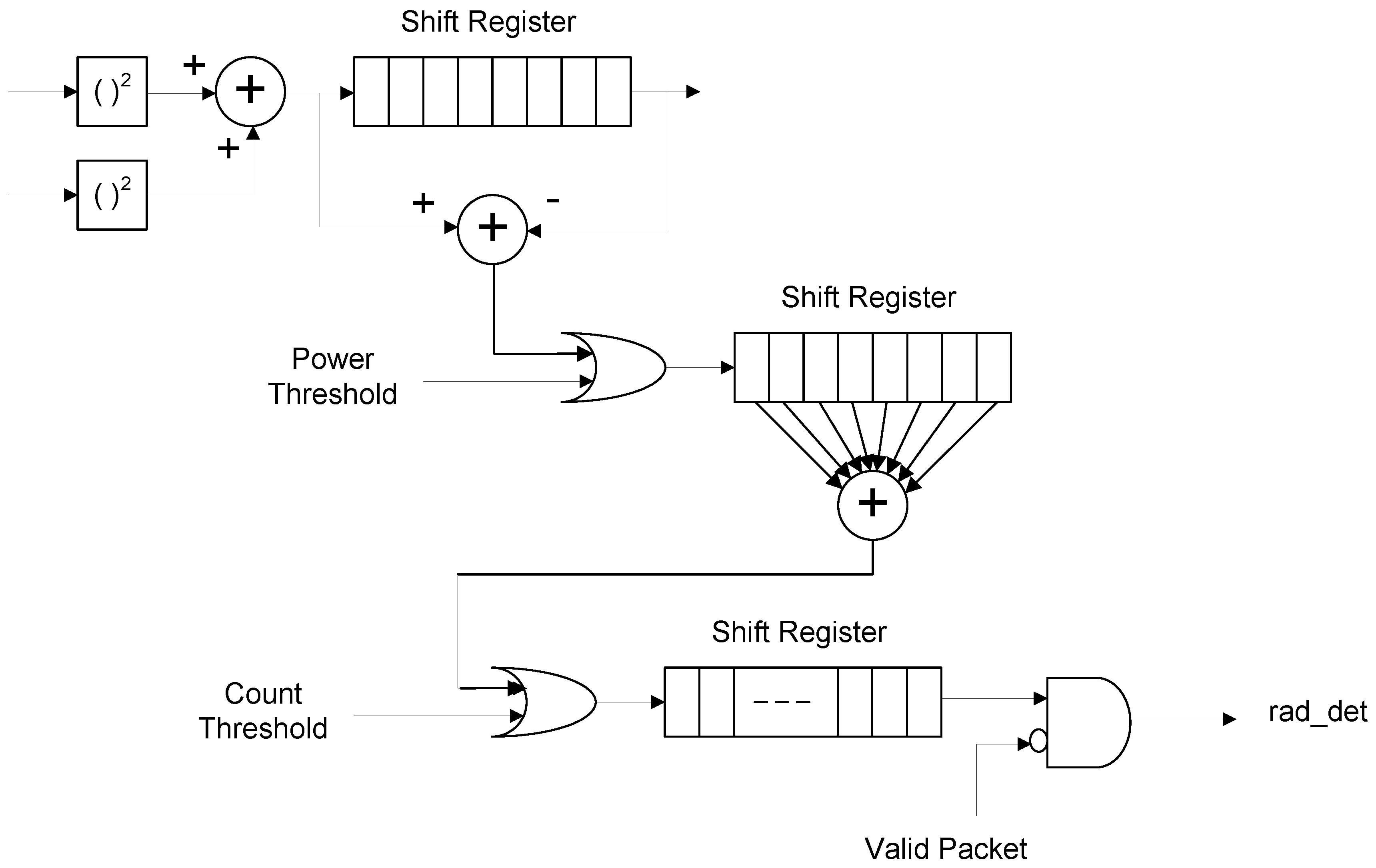
To detect the periodicity of pulses, a receiver needs to measure the pulses. Since the tone frequency and pattern are not known for all the radio devices, its power is a good measure for detecting the pulses asynchronously. Of course, the sensitivity decreases with power measurement compared to synchronous tone signal measurement. Figure 2 shows the block diagram of the implemented periodic interference detector.
Measuring the signal power requires averaging over a window. If this window is short, the averaging is not enough, so that its averaged power will not give a secure measurement. Sudden noise can crash the detection algorithm. Accordingly, it is important to have a long enough window size for averaging. The maximum window size is limited by the shortest pulse width, even as short as 0.5 µs, which is defined in Reference [14]. With this short pulse width, only 10 samples are available with 20-MHz sampling. The designed detector uses eight samples for averaging the power, that is, a window size of 0.4 µs. Thus, for every 0.4 µs, the averaged power output is passed to a comparator that compares it with a threshold and determines if there is a signal.
With this many averaging samples, the power measurement has a problem in the start time. If the start time is, inopportunely, in the middle of the 0.5-µs pulse, the two consecutive averaged powers will divide the total power of the pulse and fail to exceed a threshold. This problem can be eliminated with the moving average window. Since it is a moving average, a pulse will provide a plateau shape and the maximum power is always available. These moving averaged powers are first compared with a threshold to save the memory space instead of saving the power information. Here, the power threshold is set by WLAN standards as −62 dBm.
Wireless local area network devices can communicate through an idle channel in the unit of the 20-MHz channel, which is not used by other radios. For example, if the WLAN’s frequency bands are used by a complete 40-MHz band or upper or lower 20-MHz band, the periodic interference detection is performed for upper and lower 20-MHz bands. If WLAN uses the lower 20-MHz band and a periodic interference is detected in the same 20-MHz band, the WLAN must coordinate 20-MHz and 40-MHz transmissions so that they do not interfere with the periodic interferer. If the periodic interference is detected in the upper 20-MHz band only, the WLAN can continue to transmit 40-MHz bandwidth packets during idle time and transmit 20-MHz bandwidth packets through the lower 20-MHz band during the interference time. In the case of conventional WLANs, the WLAN must leave the lower 20-MHz band for the same conditions.
Although the periodic interference detector uses moving average power and the decision is made every clock, the decision should be time-stamped and reported to the upper layer, MAC. If this does not have a period of 0.4 µs, the time stamp value needs more accurate resolution to represent the time. In terms of a typical pulse period of 1 ms, 0.4 µs is within an error margin and finer resolution is not required. At the report time interval 0.4 µs, the periodic interference detector counts how many times the averaged power exceeds the threshold. This count value is compared with a count threshold to determine the periodic interference signal. If this count threshold is small, say 1, one peak can cause the periodic interference decision, which can increase the false alarm probability. If all eight values are to exceed the threshold, it may miss a short real interference pulse. This way of implementation increases the flexibility of the design, so that a user can change the sensibility of the periodic interference detector after the hardware is fixed.
The final decision needs to be delayed to block the valid WLAN packets. The valid WLAN packet is determined after the SIGNAL field is checked. Since the SIGNAL field comes after a short and two long preambles, and some receiver processing delay is required, 64 radar signal decision samples (0.4 µs × 64 = 25.6 µs) are delayed. If a WLAN packet valid signal occurs during this period, the periodic interference decision is nullified until the receiver enable signal is activated again.
3.2. Implementation of Secure Inter-Frame Space Communications
The periodic interference detection bit is determined and updated every 0.4 µs at the PHY. This one-bit data does not really determine the existence of the periodic interference signal, but rather the existence of a powered signal. For the determination of the periodic interference signal, this one-bit data stream needs to be saved and the periodicity of pulses should be searched to decide the existence of a periodic interference signal. Since the periodic pulses occur for durations as large as 100 ms, it is difficult for PHY to handle this long period, which is well beyond one PHY packet period. Note that the PHY enable signal is on only during PHY transmit and receive packet periods. The MAC layer usually deals with a longer period enabled continually.
The data stream of the single periodic interference detection bit is passed to the MAC layer. This interface bit is added to the existing MAC-PHY interface. The interface change is not easy once the MAC-PHY data interface is fixed. However, the periodic interference detection bit has nothing to do with WLAN packet communication. If they share the same interface, some information can be lost. For example, while WLAN packet data is being transferred to MAC, the periodic interference detection bit may lose the time to smear on the same interface path. The opposite scenario is also possible. The existing data interface is based on the packet structure. When a packet is received, PHY starts to transfer the header information with packet length information and then the received data. Putting the periodic interference detection bit data into this structure may delay the transfer of the data. It should be noted that the periodic interference detection bit does not have the pulse length information. Although the pulse length is not used for deciding the periodic interference signal, it may give additional information about the periodic interference signal. If the pulse length is excessively large, the pulse can be eliminated from the periodic interference signal category. Once the periodic interference detection bit stream is passed to the MAC layer, it should be stored so that the upper layer fetches the stored data. This raw bit stream has one bit per 0.4 µs, which provides 2500 bits per millisecond, a typical pulse period. That is, if there is one pulse during 100 ms, 250,000 bits should be stored in the worst case. Of course, there can be some false alarms, such as noise between pulses.
The important design criterion in this memory design is to save memory. One-bit memory width is not efficient either. The periodic interference detection information needs the start time and pulse length in the calculation of periodicity. In MAC, the periodic interference detection bit stream is transformed to a 32-bit time stamp format. That is, every time a periodic interference detection bit is on, the corresponding time stamp is saved. The first 22 bits represent the pulse start epoch, and the epoch has a resolution of 0.4 µs, as used in radar signal detection. Then 22 bits can represent a linear time frame of 222 × 0.4 µs = 1.6777 s. The remaining 10 bits represent the pulse length, that is, up to 210 × 0.4 µs = 409.6 µs, which can cover over 100-µs-long radar pulses. It should be noted that the pulse length information is available at the end of the pulse when the periodic interference detection bit goes from on to off. The write timing is at the end of a pulse, although the start time is already saved in the front of the pulse.
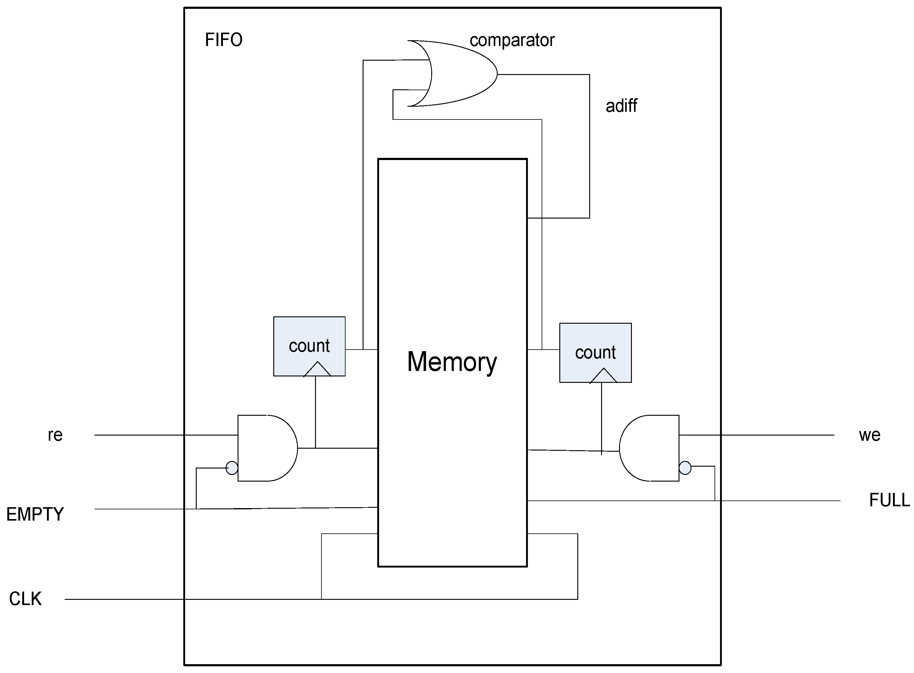
The memory depth should also be decided in terms of the write and read speeds. The write speed should be slower than the read speed, otherwise the memory will be full and subsequent data would be lost. The size of memory is set as it stores 64-bit time stamp data. This memory depth can store over approximately 1 ms if signals appear 10 times in 100 µs. Then the upper layer implemented in a CPU (Central Processing Unit) processer can have enough time to read the memory at its speed. The memory size is 64 × 32 bits = 2 Kb. This memory size can be adjusted to a smaller size if the used CPU has faster read speed. The memory is set as a circular first-in-first-out (FIFO) or FIFO with dual ports. Since the write and read timings are not synchronized, FIFO is the best choice to transfer data. The time stamps are written any time a signal is detected. The upper layer reads the FIFO any time, independently of the write timing. Figure 3 shows the diagram of the implemented FIFO.
A FIFO needs a FULL and an EMPTY signal to protect over-writing and over-reading. A dual-port FIFO has a write address and a read address, and they should be properly managed. The write and read addresses must not be twisted. The write address must be ahead of the read address continually. When the write address wraps around and points to the read address again, the FIFO should stop writing. When the read address follows and reaches the write address, the FIFO should stop reading, which is the EMPTY signal. One more logic can be found in the case when write and read enables are activated simultaneously with FIFO FULL signal. This case is a special FULL case, when write and read can work simultaneously, even in the FULL situation. There is no such case in the EMPTY situation because writing data requires one cycle. To make the FULL and EMPTY logic simple, the FIFO uses the same clock source: 40 MHz for both write and read ports.
4. Performance Evaluation
As shown in Section 3, a radar signal consists of a train of pulses that typically have a short pulse width and narrow frequency band. That is, a transmitted radar signal is a simple sinusoidal wave modulated by On-Off keying or OOK. In this case, the important design aspect is to control the timings of pulses and bursts. To test several different types of radar signal pulses, it is important to set the signal parameters, such as PRF, pulse width, and burst period, as input parameters so that the simulator can change them easily.
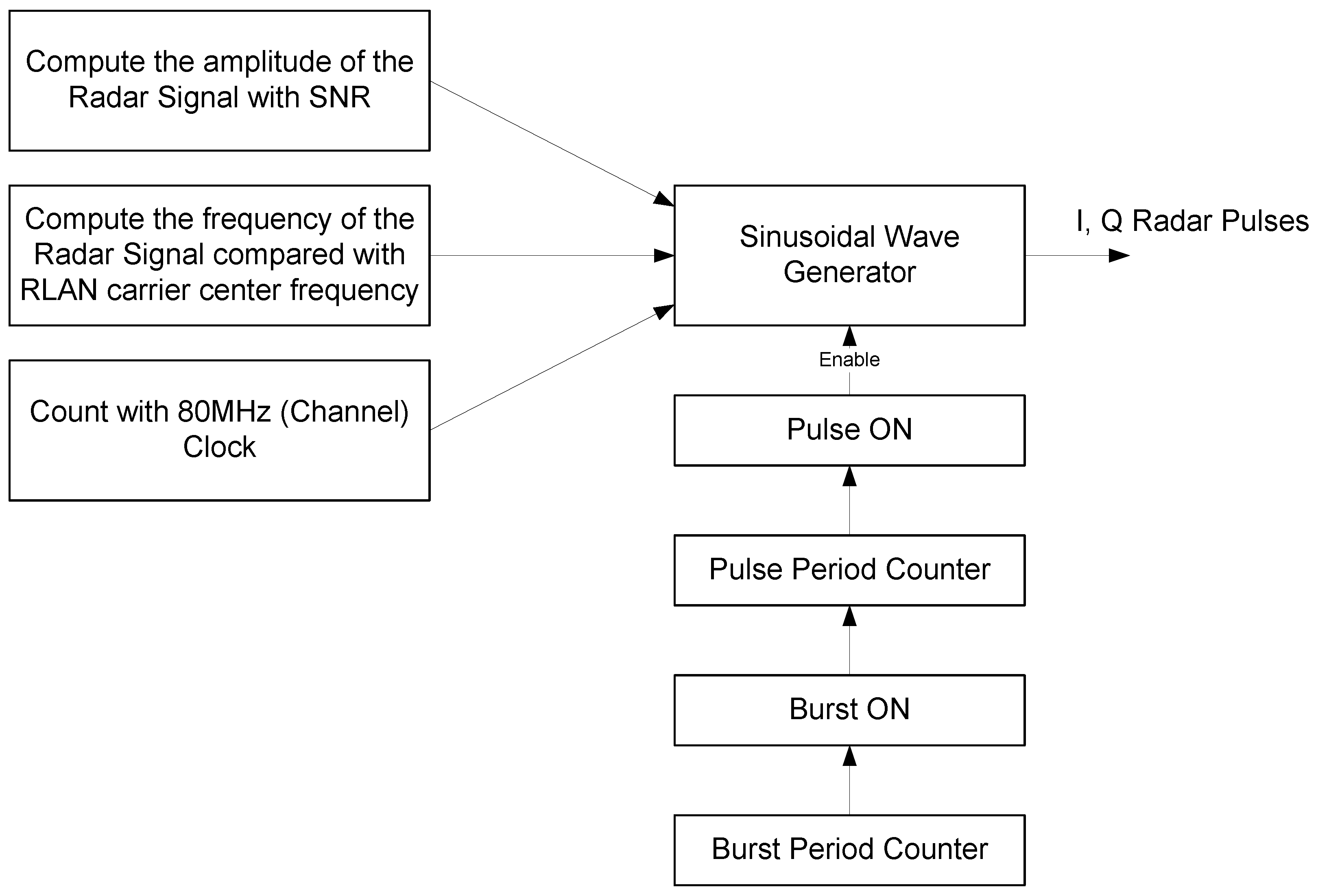
Figure 4 shows the block diagram of the radar transmitter. With the input signal parameters set by a user, the signal power, frequency, and phase are computed and then fed into the sinusoidal generator. On the other hand, the timings of the pulse train are computed with counters, burst counter, and pulse counter. The pulse ON signal enables the sinusoidal wave generator to output the radar signal pulses.
The channel is assumed static throughout a burst and generated independently for each burst. The impulse response of the channel is composed of complex samples with randomly distributed phase and Rayleigh distributed magnitude with the average power decaying exponentially. In the simulation model, the WLAN data sender and receiver, which have the proposed radar detector and secure inter-frame space communications system at 5 GHz, are modeled in the C programming language.
A periodic interference detection algorithm has been designed and implemented. The designed algorithm utilizes the periodic property of the interferences. To do this, the periodic interference detector first measures the received signal power averaged over a moving window. The decision is saved in a shift register to cover a period of interference detection. The count of the decisions is compared with a threshold again. The final decision is delayed to see if the received signal is a valid packet.
The detection of the periodic interference is with PHY, while the decision bit stream is passed to the MAC layer. The MAC layer transforms the one-bit stream into a 32-bit time stamp driven by signal detection activation. The transformed time stamps are stored and the upper layer fetches this information to search the periodic interference patterns. Finally, WLAN factors are considered to decide the presence of the periodic interferences. Periodic interference detection is not only a power detection problem, but also a network problem in the WLAN stations. The nodes and access point should cooperate together to detect the periodic interferences.
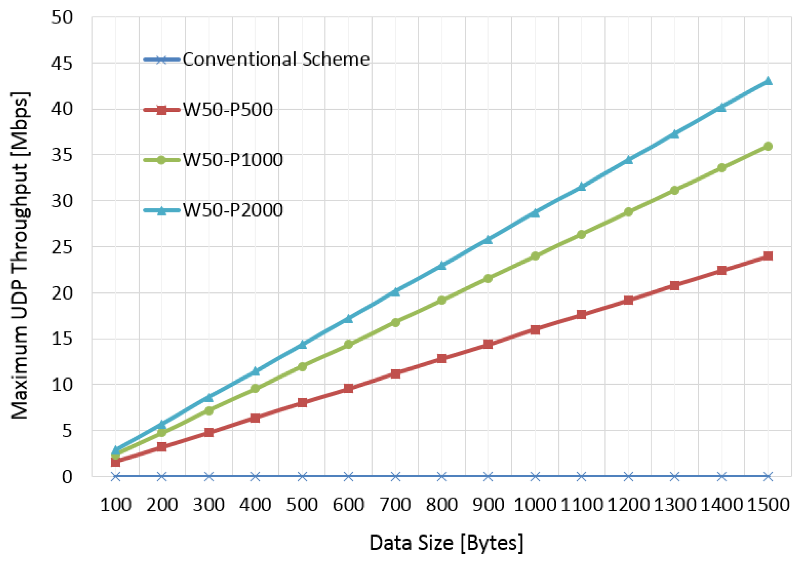
Figure 5 demonstrates the improved detection performance of the proposed detection scheme, and Figure 6 shows the improved maximum user datagram protocol (UDP) throughput. The simulation model was built on the bit- and cycle-accurate C simulator which is the same model used for the implemented commercial chipset and was certified through standard Wi-Fi certification process. In Figure 5 and Figure 6, “PRO” and “CON” refer to the proposed scheme and conventional scheme, respectively. Ten thousand radar samples were used for this test. “W” and “P” refer to pulse width and periodicity of radar signals, respectively. As a result, shorter pulse width and periodicity result in performance degradation due to the limited resolution of the detector. However, the proposed scheme outperformed for test scenarios. In Figure 6, W50-P2000 was much better than W50-P500 because short periodicity increased the interfered duration. However, all the cases of the proposed scheme outperformed when compared with the conventional scheme.
In conventional WLAN systems, once a periodic interference signal is detected within the basic service set either by an access point or station, they must follow the rule to escape the channel and search another clearer channel. The channel search can also be done by all stations as well as access points. The searched results are gathered at the access point. The access point broadcasts a move command to every station and finishes DFS within a specified time period. These steps are performed in the MAC layer with the support of the upper layer. On the other hand, in the proposed secure inter-frame communication, the wireless device could achieve significant throughput improvement by adopting periodic interference detection and data transmission in the secure inter-frame space.
5. Conclusions
In this paper, a secure inter-frame space communication system was designed and its simulation model was implemented. To design the secure inter-frame space communication algorithm, the characteristics of periodic interference signals were investigated. Although most periodic interference signals have similar properties such as pulse width, pulse period, and burst period, some military radios, such as radars, do not reveal their parameters. To implement the special-purpose periodic interference signals, all the parameters should be set as adjustable parameters. The periodic interference signal generators have been implemented in the WLAN C models and a pulse train is available to test the proposed algorithm. Since a periodic interference signal is generated independently of WLAN communication packets, the secure inter-frame space communication algorithms could be tested either alone or together with WLAN packets. One of major security requirements of wireless networks is availability issue. The availability refers to ensuring that the authorized users are indeed capable of accessing a wireless network when needed. The violation of availability, caused by interferences, will results in the authorized users to become unable to access the wireless network. The proposed secure inter-frame space communications scheme improves the availability under the interfered environments. As future work, the secure inter-frame space communication system will be implemented and demonstrated in a real testbed, and optimization issues for more than one radar will be investigated in the real testbed and the performance analyzed theoretically including mathematical models.
Funding
This work was supported by the Sungshin University Research Grant of 2017-1-11-055/1.
Conflicts of Interest
The author declares no conflict of interest.
References
- Jun, J.; Peddabachagari, P.; Sichitiu, M. Theoritical maximum throughput of IEEE 802.11 and its applications. In Proceedings of the Second IEEE International Symposium on Network Computing and Applications, Cambridge, MA, USA, 18 April 2003. [Google Scholar]
- Sun, W.; Lee, O.; Shin, Y.; Kim, S.; Yang, C.; Kim, H.; Choi, S. Wi-Fi could be much more. IEEE Commun. Mag. 2014, 52, 22–29. [Google Scholar] [CrossRef]
- Doering, M.; Budzisz, L.; Willkomm, D.; Wolisz, A. About the practicality of using partially overlapping channels in IEEE 802.11b/g networks. In Proceedings of the 2013 IEEE International Conference on Communications (ICC), Budapest, Hungary, 9–13 June 2013; pp. 5110–5114. [Google Scholar]
- Mehrnoush, M.; Roy, S. Coexistence of WLAN Network with Radar: Detection and Interference Mitigation. IEEE Trans. Cogn. Commun. Netw. 2017, 3, 655–667. [Google Scholar] [CrossRef]
- Arslan, M.Y.; Pelechrinis, K.; Broustis, I.; Singh, S.; Krishnamurthy, S.V.; Addepalli, S.; Papagiannaki, K. ACCORN: An auto-configuration framework for 802.11n WLANs. IEEE/ACM Trans. Netw. 2013, 21, 896–909. [Google Scholar] [CrossRef]
- Rayanchu, S.; Shrivastava, V.; Banerjee, S.; Chandra, R. FLUID: Improving throughputs in enterprise wireless LANs through flexible channelization. IEEE Trans. Mob. Comput. 2012, 11, 1455–1469. [Google Scholar] [CrossRef]
- Institute of Electrical and Electronics Engineers. IEEE Standard for Information Technology—Telecommunications and Information Exchange between Systems—Local and Metropolitan Area Networks—Specific Requirements—Part 11: Wireless LAN Medium Access Control (MAC) and Physical Layer (PHY) Specifications—Spectrum and Transmit Power Management Extensions in the 5 GHz Band in Europe; IEEE Standard 802.11 h; IEEE: Piscataway, NJ, USA, 2003. [Google Scholar]
- M.1652: Dynamic Frequency Selection (DFS) in Wireless access Systems Including Radio Local Area Networks for the Purpose of Protecting the Radio Determination Service in the 5 GHz Band. Available online: http://www.itu.int/rec/R-REC-M.1652/en (accessed on 4 June 2018).
- Institute of Electrical and Electronics Engineers. IEEE Standard for Information Technology—Telecommunications and Information Exchange between Systems—Local and Metropolitan Area Networks—Specific Requirements—Part 11: Wireless LAN Medium access Control (MAC) and Physical Layer (PHY) Specifications—Amendment 4: Enhancements for Very High Throughput for Operation in Bands Below 6 GHz; IEEE Standard 802.11ac; IEEE: Piscataway, NJ, USA, 2013. [Google Scholar]
- Afaqui, M.S.; Garcia-Vilegas, E.; Lopez-Aguilera, E. IEEE 802.11ax: Challenges and Requirements for Future High Efficiency WiFi. IEEE Wirel. Commun. 2017, 24, 130–137. [Google Scholar] [CrossRef]
- Chiodini, A. Radar Detector and Radar Detecting Method for Wireless LAN Systems according to 802.11 Wireless Communication Standard. U.S. Patent 7280067 B2, 9 October 2007. [Google Scholar]
- McFarland, W.; Zeng, C.; Dhamdhere, D. Radar Detection and Dynamic Frequency Selection for Wireless Local Area Networks. U.S. Patent 6697013 B2, 24 February 2004. [Google Scholar]
- Jamshid, K.J. Wireless Communication System with Detection of Foreign Radiation Sources. U.S. Patent 7024188 B2, 4 April 2006. [Google Scholar]
- Wi-Fi Alliance Spectrum & Regulatory Committee. Spectrum Sharing in the 5 GHz Band DFS Best Practices 2007. Available online: http://www.ieee802.org/18/Meeting_documents/2007_Nov/WFA-DFS-Best%20Practices.pdf (accessed on 4 June 2018).
Figure 1.
Block diagram of the dynamic frequency selection (DFS) algorithm.

Figure 2.
Block diagram of periodic an interference detector.

Figure 3.
Block diagram of first-in-first-out (FIFO) to store time stamps of radar detect signals.

Figure 4.
Block diagram of the radar transmitter.

Figure 5.
Detection error probability vs. radar input power.

Figure 6.
Maximum user datagram protocol (UDP) throughput vs. data size.

© 2018 by the author. Licensee MDPI, Basel, Switzerland. This article is an open access article distributed under the terms and conditions of the Creative Commons Attribution (CC BY) license (http://creativecommons.org/licenses/by/4.0/).
Share and Cite
MDPI and ACS Style
Lee, I.-G. Secure Inter-Frame Space Communications for Wireless LANs. Future Internet 2018, 10, 47. https://doi.org/10.3390/fi10060047
AMA Style
Lee I-G. Secure Inter-Frame Space Communications for Wireless LANs. Future Internet. 2018; 10(6):47. https://doi.org/10.3390/fi10060047
Chicago/Turabian StyleLee, Il-Gu. 2018. "Secure Inter-Frame Space Communications for Wireless LANs" Future Internet 10, no. 6: 47. https://doi.org/10.3390/fi10060047
Note that from the first issue of 2016, this journal uses article numbers instead of page numbers. See further details here.