Markup in Engineering Design: A Discourse

1
Department of Mechanical Engineering, University of Bath, UK
2
School of Business and Management, University of Plymouth, UK
*
Author to whom correspondence should be addressed.
Future Internet 2010, 2(1), 74-95; https://doi.org/10.3390/fi2010074
Submission received: 4 January 2010
/
Revised: 26 February 2010
/
Accepted: 2 March 2010
/
Published: 11 March 2010
(This article belongs to the Special Issue Metadata and Markup)
Abstract
:Today’s engineering companies are facing unprecedented competition in a global market place. There is now a knowledge intensive shift towards whole product lifecycle support, and collaborative environments. It has become particularly important to capture information, knowledge and experiences about previous design and following stages during their product lifecycle, so as to retrieve and reuse such information in new and follow-on designs activities. Recently, with the rapid development and adoption of digital technologies, annotation and markup are becoming important tools for information communication, retrieval and management. Such techniques are being increasingly applied to an array of applications and different digital items, such as text documents, 2D images and 3D models. This paper presents a state-of-the-art review of recent research in markup for engineering design, including a number of core markup languages and main markup strategies. Their applications and future utilization in engineering design, including multi-viewpoint of product models, capture of information and rationale across the whole product lifecycle, integration of engineering design processes, and engineering document management, are comprehensively discussed.
1. Introduction
More and more contemporary companies are shifting their business paradigm from design and manufacture of artefacts to the provision of through-life support, leading to a knowledge intensive product, covering a large area, not only engineering issues, but human and business related, spanning the whole product life cycle [1,2]. In addition to this, the global economy has increased the amount of collaboration that happens within modern engineering design practices. With designers located in disparate locations, it is becoming particularly important (and more difficult) to capture, exchange and reuse the information and experiences generated during these design activities.
Engineering design is the use of scientific principles, technical information and imagination in the definition of a mechanical structure, machine or system to perform pre-specified functions with the maximum economy and efficiency [3]. Generally, the design process can be regarded as a series of activities, which aim to create a desired artefact. Included in this process are: decision-making, problem-solving, rationale related to decisions, and various information resources (such as catalogues, design/factory guidelines, and properties databases). During the last decades, there has been a lot of work carried out to support engineering design in both the academic and commercial communities. Recent examples have been a number of Computer Aided Design (CAD) systems [e.g. 4,5,6], various design process models [e.g. 7,8,9] and rationale tools [e.g. 10,11], and several techniques for Computer Supported Cooperative Work (CSCW) [e.g. 12,13]. However, in today’s industry, such traditional supporting tools are still insufficient due to various limitations, e.g. lack of engineering context and semantics in CAD models, extra manual work needed, etc.
Recently, with the rapid development and adoption of digital technologies, annotation and markup are attracting more and more attentions for information communication, retrieval and management. Correspondingly, some critical research work has already been conducted on supporting and capturing engineering design process. This paper presents a state-of-the-art review of recent research in markup for engineering design aiming to provide a complete view of markup on requirements, technique status, applications and future directions. The subsequent content is organized as follows. Section 2 introduces the definition and classification of annotation and markup. Section 3 and section 4 review the current core markup languages and markup strategies, respectively. Their applications and future utilization in engineering design, including engineering document management, support of multi-viewpoint, product lifecycle information support, design communications in collaborative environment, and integration of engineering design processes, are comprehensively discussed in section 5. Finally, conclusions are drawn in section 6 and future research directions are suggested based on the discussion in section 7.
2. Annotation and markup
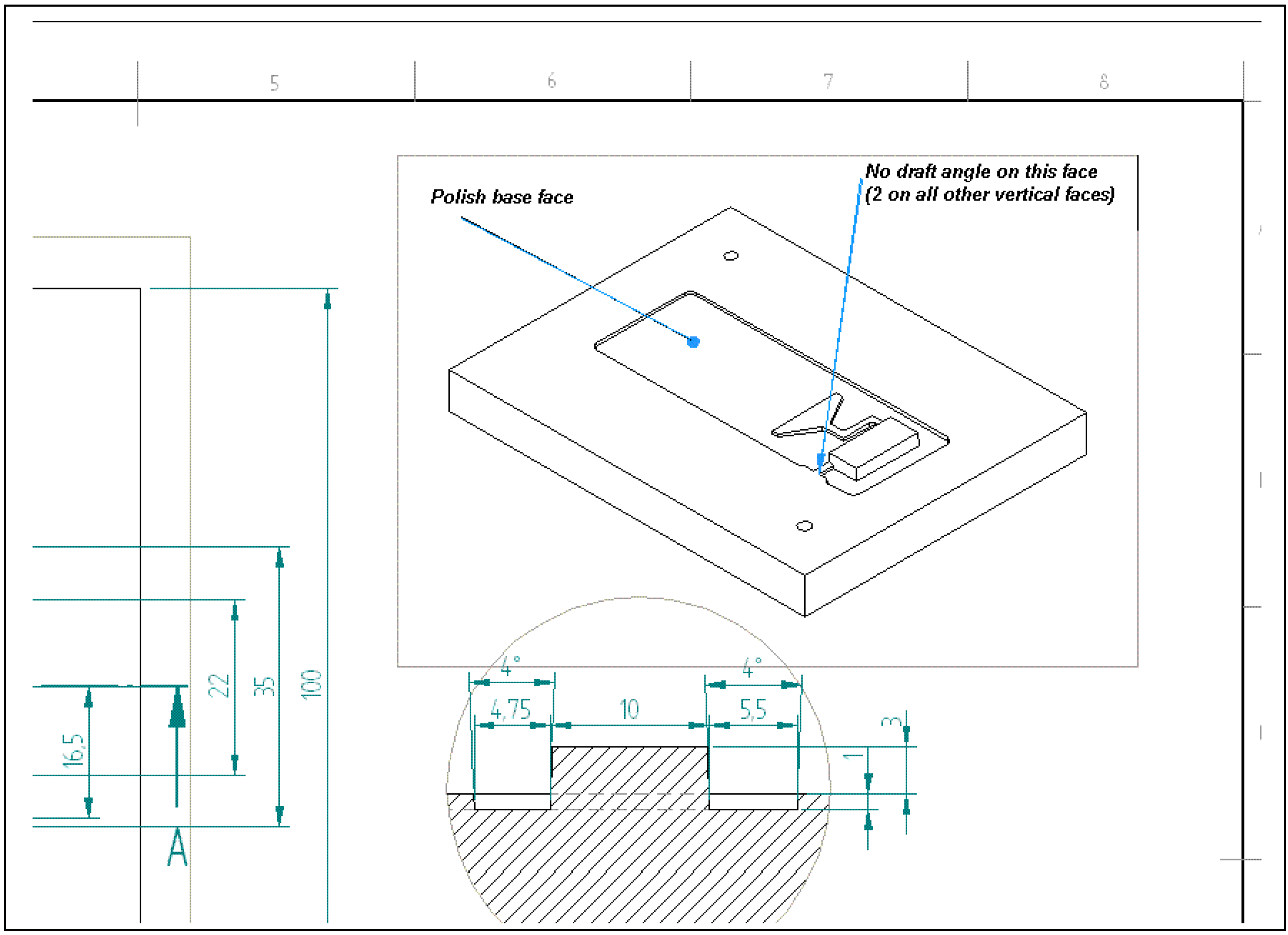
Annotation can be simply understood as the act of adding additional information for various purposes, such as commentary, viewpoint interpretation or extra description. Annotation has been a part of engineering practice to aid communication for a long time, for example, engineers discuss the product face-to-face through annotating a design drawing, or sending an annotated drawing of a product to colleagues (an example is shown in Figure 1). Markup may have different definitions according to its application domains, such as the publishing industry or in the world of computer science. In this paper, markup is regarded as a subtype of annotation and is defined as a formally structured annotation for a purpose, normally to allow some kind of manipulation of the information entity [14]. Over last two decades, many mark-up methods have been developed and these can be classified into six basic categories [15,16,17]:
- 1)
- Punctuational mark-up: where word, phrase, and sentence boundaries are identified by spaces, commas, full stops, and other punctuation characters inserted into the text.
- 2)
- Presentational mark-up: where the visual form of the document is specified directly.
- 3)
- Procedural mark-up: in which presentational instructions (or commands) for some particular processing system are embedded in the text.
- 4)
- Descriptive mark-up: the author identifies the element types as tokens, as often found in applications of SGML and XML, which approach documents as structured objects containing semantically interpretable parts.
- 5)
- Referential mark-up: refers to entities external to the document and is replaced by those entities during processing.
- 6)
- Meta-mark-up: provides a facility for controlling the interpretation of mark-up and for extending the vocabulary of descriptive mark-up languages (e.g. macros).
Figure 1.
An example of annotation

To date, digital information has predominately been stored in different structures and formats depending on which specific software being used. However, it is normal that such information needs to be translated into different formats (e.g. Microsoft word format, HTML, PDF) for purposes such as presentation and accessibility in different contexts. A typical example is graphs of experimental results embedded in Microsoft Word document. Such traditional methods succeed in visualization of graphs, but fail by missing other information, like how the results were produced and the raw data which they represent. In terms of solving this issue, descriptive markup is able to show potential benefits. Firstly, the descriptive markup allows users to focus on both the structure and content of document so it has greater portability. Secondly, descriptive markup separates how data is stored and how it is used and therefore can potentially provide any additional information required when transforming the object to different formats for the different purposes or when to be re-processed or re-organized for different applications and uses.
To allow markup to be implemented and to serve applications in engineering design, it is essential to have adequate understanding of markup languages and strategies. These will be discussed in the next two sections.
3. Markup languages
The classes of markup methods usually co-occur in practice, though many markup languages are initially designed to support a specific markup method. For examples, the eXtensible Markup Language (XML) is explicitly developed for descriptive markup, but it can also be extended to support referential and meta-markup; and the HyperText Markup Language (HTML) includes both procedural and descriptive markup elements. Thus, this section will review markup languages based on their application purposes, not the markup classes: firstly, languages for text markup; secondly, markup languages for graphics and images; and finally, markup languages for web applications (to support virtual, collaborative design environment in particular).
3.1. Markup languages for text documents
A mark-up language is a formalised way of providing markups [18]. There are dozens or maybe hundreds of mark-up languages in use today. The first structured markup language is IBM’s Generalized Mark-up Language (GML) [19]. Based on the GML, the Standard Generalized Mark-up Language (SGML) was developed in the 1970s and became an international standard in 1986. SGML is not a language per se but rather a meta-language – a rule set or toolkit for developing markup languages, such as HTML. HTML allows the markup of electronic documents for manipulation with regard to formatting and presentation, but the presentation specialisation makes HTML documents difficult to be processed for other purposes. To overcome the limitations of HTML, XML was created. Different from HTML, XML allows users to define their own tags (i.e., the labels that are embedded within text to distinguish individual/groups elements for display or identification purposes) based on the specific needs of a document, and therefore it is extensible. Further, as XML tag names are normally transferred from the meaning of the data and therefore they are readable. Each XML tag immediately precedes the associated data, which makes the data structure easily understandable by both humans and computers. In addition, one of most important powers of XML lies in the separation of specifications of valid tags; valid structure for data contained in elements; the valid type of data that each element may contain and what manipulations should be applied to elements identified by the tag, the information and its presentation. This offers the possibility to manipulate XML-based documents in multiple ways based on their markup. Thus, XML has become one of the most common computer-interpretable markup languages and been widely employed and implemented in engineering design. Further work in this stream are the many modifications and versions of mark-up languages based on XML which have been developed for different engineering scenarios. For example, DML (Dimensional Mark-up Language) was discussed for closed-loop CAPP/CAM/CNC process chain based on STEP and STEP-NC [20]. To provide designers with a product data exchange standard and support product lifecycle management, Lee et al. proposed a Product Information Mark-up Language (PIML) [21]. A framework of XRML (eXtensible Rule Mark-up Language) developed by Kang and Lee allows the identification of rules on Web pages and extracts the identified rules automatically from Web pages to maintain consistency of text and table information [22]. In [23], a Motion Capture Mark-up Language (MCML) was proposed. The purpose of the MCML is not only to facilitate the conversion or integration of different formats, but also to allow for greater reusability of motion capture data, through the construction of a motion database storing the MCML documents.
3.2. Markup languages for graphics and images
With the increasing requirements of retrieval of images and graphics, there are a number of markup languages specific to graphics which have been introduced. Firstly, SVG [24], Scalable Vector Graphics, is a novel XML-based language for describing two-dimensional graphics at the level of graphical objects rather than individual points. SVG is now a W3C (World Wide Web Consortium) [25] standard. SVG is becoming increasingly popular due to its inherent advantages over raster image formats. SVG can work with three types of graphical objects: vectorial graphical shapes (such as lines and primitive shapes), text and images (equivalent to raster image retrieval). The creation of SVG was attributed from other two XML applications for encoding vector information. They are VML (Vector Markup Language) [26] and PGML (Precision Graphics Mark-up Language) [27]. VML defines a format for vector information together with additional markup to describe how that information may be displayed and edited, and is currently used by Google Maps for rendering vectors when running on IE 5.5 or late. On the other hand, PGML is designed to meet precision needs of graphics artists besides simple vector graphics needs of casual users. Both VML and PGML were submitted to W3C as proposed standards in 1998, but failed, and then joined and improved upon to create SVG. X3D (eXtensible 3D) [28], the successor to VRML (Virtual Reality Modelling Language) [29], was introduced for real-time three-dimensional computer graphics and is now an ISO standard. X3D features many extensions to VRML such as Humanoid Animation, NURBS and GeoVRML, the ability to encode the scene using XML syntax as well as the Open Inventor-like syntax of VRML97, and enhanced application programmer interfaces (APIs). In recent years, SVG and X3D have been utilised in engineering domain such as design and manufacturing systems, especially for representation of product models and provision with complex engineering data for applications such as CAD/CAPP/CAM [30]. Commercial industry has recently also developed some XML-based format for lightweight 3D model. For examples, 3D XML enables users to access and share accurate 3D data quickly and easily [31] through a sophisticated 3D graphics compaction algorithm based on NURBS surface mathematics. PLM XML [32], an XML-based PLM format, is created and supported by UGS. The objective of PLM XML is to integrate collaborative product lifecycle processes by offering a standardised protocol for data interoperability.
3.3. Markup languages for web applications
Another important development of markup languages is for applications on web services, such as resource description, ontologies, interoperability standards and so on. For examples, the Resource Description Framework (RDF) [33], the Web Ontology Language (OWL), Commerce XML (cXML), SOAP (Simple Object Access Protocol), WSDL (Web Service Description Language), and XML-RPC (Remote Procedure Calls) are the key contributors. RDF integrates a variety of applications from library catalogues and world-wide directories for the syndication and aggregation of news, software, and content to personal collections of music, photos, and events using XML as an interchange syntax [33]. As a lightweight ontology system, the RDF specifications support the exchange of knowledge on the Web. The OWL [34] is designed for use when the information contained in documents needs to be processed by applications, as opposed to situations where the information only needs to be presented to humans. As implied in its name, OWL can be used to explicitly represent “ontology”, which consists of the meaning of terms in vocabularies and the relationships between those terms. cXML [35] is a well-defined, robust language designed for consistent communication of business documents between procurement applications, e-commerce hubs and suppliers. cXML is defined by a set of lightweight XML DTDs and its transactions consist of documents, which are simple text files containing values enclosed by predefined tags. SOAP defines the XML-based message format that Web service-enabled applications use to communicate and interoperate with each other over theWeb [36]. Based on SOAP, WDSL is a collection of metadata about XML-based services used to specify the procedures to discover functional and technical information about Web services over the Web [37]. XML-RPC is a remote procedure call protocol that uses XML to encode its calls and HTTP (Hypertext Transfer Protocol) as a transfer mechanism [38]. These XML-based standards enable applications to call functions from other applications, running on any hardware platform regardless of operating systems or programming languages, and have started finding their positions to play a central role in building and integrating enterprise applications. For instance, Umar discusses the application of SOAP, WSDL together with UDDI (Universal Description, Discovery and Integration) to enterprise boundaries business-to-business (B2B) trade and outsourcing through application service providers (ASPs) [39]. Comparatively, Bussler argues that the traditional Web service triplets SOAP, WSDL and UDDI allow enterprise application integration and B2B integration only possible at syntactic level, and therefore advocates using XML-RPC to enable semantic level integration [40].
Table 1 summarizes the core markup languages.

| Language | Based on | Developer | Initial release | Major applications |
|---|---|---|---|---|
| Generalized Mark-up Language (GML) | _ | IBM | 1960s | Document |
| Standard Generalized Mark-up Language (SGML) | GML | ISO | 1986 | Document |
| HyperText Markup Language (HTML) | SGML | W3C & WHATWG | 1991 | The World Wide Web |
| eXtensible Markup Language (XML) | SGML | W3C | 1996 | Arbitrary data structures |
| Dimensional Mark-up Language (DML) | XML | NIST | _ | CAPP/CAM/CNC |
| Product Information Mark-up Language (PIML) | XML | Lee et al. | 2005 | PLM |
| eXtensible Rule Mark-up Language(XRML) | XML | Kang and Lee | 1998 | Web information |
| Motion Capture Mark-up Language (MCML) | XML | Chung and Lee | 2003 | Motion capture data |
| Scalable Vector Graphics (SVG) | XML | W3C | 2001 | 2D graphics |
| Vector Markup Language(VML) | XML | Autodesk, Hewlett-Packard, Macromedia, Microsoft, Visio | 1998 | Vector information together with additional markup |
| Precision Graphics Mark-up Language(PGML) | XML | Adobe Systems, IBM, Netscape, Sun Microsystems | -- | Vector graphics |
| X3D (eXtensible 3D) | XML/VRML | W3C/ISO | _ | 3D graphics |
| 3D XML | XML | Dassault Systemes | -- | 3D data |
| PLM XML | XML | UGS. | -- | PLM information |
| Description Framework (RDF) | W3C | 1999 | Web resources | |
| Web Ontology Language (OWL) | RDF/XML | W3C | 2002 | Web ontology language |
| Commerce XML (cXML) | XML | more than 40 companies | 1999 | e-commerce |
| Simple Object Access Protocol (SOAP) | XML | W3C/ Microsoft, IBM, DevelopMentor, UserLand Software) | 2003 | Web service |
| Web Service Description Language (WSDL) | XML | W3C /IBM, Microsoft, Ariba) | 2000 | Web services |
| Remote Procedure Calls (XML-RPC) | XML | Dave Winer of UserLand Software and Microsoft | 1998 | Internet |
4. Mark-up strategy
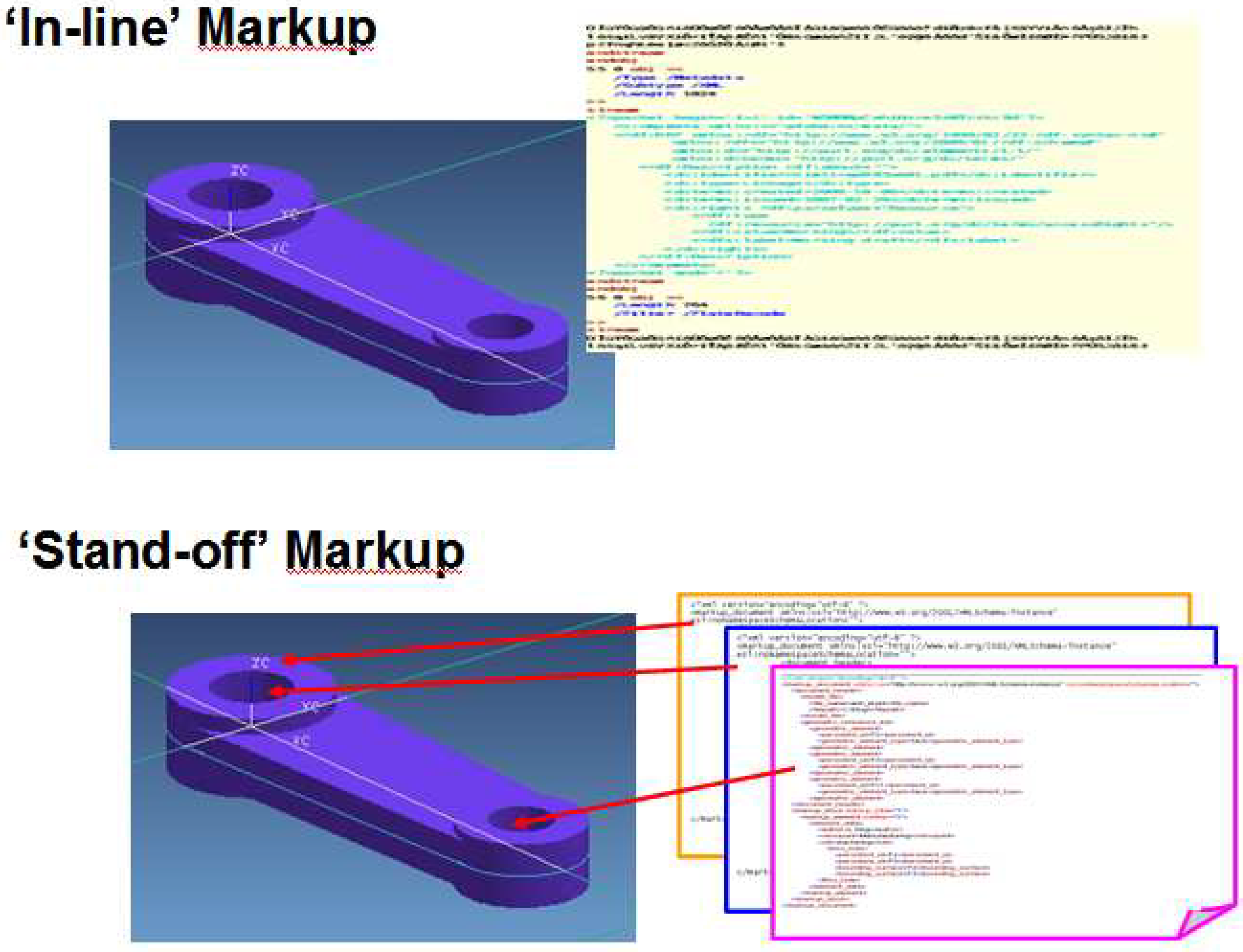
The conventional method of markup of a document is ‘in-line’ with the text of the documents - i.e. text markup labels merged into a text document. From a computer system’s point of view, the markups change a document from a long sequence of strings to a block of information with semantic meaning. The ‘in-line’ markup method is easily accomplished using a text editor or a simple scripting language, and therefore it has become one of the most commonly used methods. However, there are some disadvantages of the ‘in-line’ markup method. For example, as the method inserts markup directly into the text of the document, it actually changes the document. As the markup labels are embedded in the document, it is difficult to place multiple independent sets of markup in the same document without them interfering with each other.
To overcome this, an alternative method called ‘stand-off’ markup [41,42] is introduced. Different from ‘in-line’ markup, the content in the ‘stand-off’ markup is stored in separate external documents utilizing a system of references or pointers to which element the markup refers. The work of Ding et al. [14], Davies and McMahon [43] and Alink [44], has shown that the ‘stand-off’ markup method has many advantages over “in-line” markup, including:
- It allows original digital object (i.e. including both documents and various digital model) progressively to expand to include extra information (e.g. semantic context and rationale behind) and metadata without changing the representation method used for the original object. Thus, it provides a good tool to support the continuous update of information throughout a product lifecycle.
- Many layers of markup can be associated with the same object, allowing different viewpoints to be associated with, both concurrent viewpoints (e.g. cooperators or partners during the design phase) and successive (e.g. technology requirements from machining engineers or maintenance information from in-service phase). That is, with ‘stand-off’ markup, information from various viewpoints with different structures or formats can be carried, while the original object itself however, remains ‘light’ and can be passed with only the information necessary for a specific user or purpose.
- The information pertaining to one viewpoint can be put in a separate markup file; and multiple independent markup files can be safely applied to the same object. Thus, it allows context-specific information to be manipulated into different viewpoints, freely tailored to a reduced version for reasons of security/IP (Intellectual Property) and the requirements of different target users, and re-organized for various purposes and applications.
The major disadvantage of ‘stand-off’ markup is how to implement it, specifically how to get robust, persistent references back to the object and how to link from the object to the markup?
Table 2 summarizes advantages and disadvantages of the two strategies.
| Markup strategy | Advantages | Disadvantages |
|---|---|---|
| ‘in-line’ |
|
|
| ‘stand-off’ |
|
|
Although more work is needed on its implementation, comparing to ‘in-line’ markup, the application of the ‘stand-off’ markup has shown more great potential in engineering design, particularly on the trend to management of product information throughout its lifecycle. In general, product information encompasses a vast heterogeneous range of information, required and produced by many different individuals and groups who interact with the product throughout its lifecycle. Each of these actors requires different subsets of the product information and different structuring of the information. In addition, 3D digital product models (i.e. CAD models) have already dominated in industry design. The structure of CAD models (e.g. B-rep) is designed for representing 3D geometrical information, but has only limited capabilities for storing markups natively. Meanwhile, a number of geometrical representation methods make it uneconomical or even impossible to insert various types of markups using the ‘in-line’ method. The ‘stand-off’ approach, however, allows markup information to be stored in separate documents and linked back to the model using references or pointers, and therefore it actually extends the product models to additional engineering and non-engineering information not currently supported by the established formats. This will be further discussed in the next section.
Figure 2 shows the comparison of ‘in-line’ and ‘stand-off’ markup methods.
Figure 2.
‘In-line’ and ‘Stand-off’ markup methods.

In practice, markup is usually done manually, semi-automatically or automatically according to how much human effort is involved. Manual mark-up is the most popular, most accurate (with human interpretation) but most labour-intensive. Automatic mark-up reduces manual intervention and gives a more integral representation of the documents.
There are limited publications which are concerned with automatic and hybrid mark-up. For example [45,46,47], explored automatic mark-up with different methods and targeting on different types of documents. In [45], the authors reported on the design and implementation of a system which automates the process of capturing structured documents from the optically recognised form of printed materials to elements like words, sentences, title, authors, etc. but not for logical content elements. A novel system that can automatically markup text documents into XML is discussed in [46]. The system uses a self-organising map (SOM) algorithm and inductive learning algorithm. Experiments were carried out with business letters. The system can extract elements like address, date, salutation, paragraph and closing, etc. This system is adaptive in nature and learns from errors to improve mark-up accuracy. Cui discussed an automatic mark-up system which is based on machine learning methods and enhanced by machine learned domain rules and conventions [47]. The work is concentrating on taxonomic descriptions of plants (flora). Although machine learning systems are state of the art, especially for simple tagging problems, knowledge-based systems (mostly rule-based) have traditionally been the top performers in most information extraction benchmarks, and still retain some advantages. Feldman, Rosenfeld and Fresko propose a hybrid semantic tagging approach, which combines the power of knowledge-based and statistical machine learning [48]. The rules for the extraction grammar are written manually, while the probabilities are trained from an annotated corpus. The experiments show that the hybrid approach outperforms both purely statistical and purely knowledge-based systems. Vargas-Vera et al. present an annotation tool that provides both automated and semi-automated support for marking up Web pages with semantic contents [49].
5. Applications of markup in Engineering Design
Effective and efficient engineering design processes are always crucial in determining the capabilities, costs and other attributes of artefacts. With rapid globalisation and technological innovation, engineering design is being expanded to an intensive-knowledge and global involvement process. Recently, digital markup has played a more and more important role in product development due to its various advantages, such as capabilities of representation of weakly structured information, support of multi-viewpoint visualisation. In this section, the main achievements of employing markup in supporting engineering design process are reviewed.
5.1. Markup for information management and retrieval
As engineering companies move to digital strategies, such as digital representations for geometrical product (i.e. CAD models), experimental data (e.g. spreadsheet) and design report (e.g. word processor), the effective retrieval of the information becomes a key issue. Information retrieval is one of the earliest domains that has widely employed markup, especially in document management. For examples, Kim and Compton [50] proposed a Web-based document management and retrieval system supported by annotation techniques. The proposed method allows users to freely annotate their documents and to find appropriate annotations for new documents. Based on these annotations, any relevant documents can be easily organised and retrieved using the concept lattice of formal concept analysis (FCA). Soo et al. [51] established a framework for facilitating image retrieval based on a sharable domain ontology and thesaurus. In the proposed framework, the documents to be retrieved are annotated with semantic tags that are defined and derived from a set of domain concepts or schemes called domain ontology and thesaurus. The annotations could be converted with user queries into semantic web RDF format with the aid of a sharable domain ontology and thesaurus. Finally, the information can be retrieved at an abstract and “semantic” level, rather than the purely syntactic keyword matching level. The shared ontology is also used in the method proposed by Gardoni [52], and Frank and Gardoni [53], called ANnotation tool for Industrial TeAms (ANITA). The ANITA uses the shared ontology to index documents and parts of documents through manual annotation. Based on these annotations, the system is able to manipulate and explore written information content for groups of researchers with similar research interests. In addition, authors also clarify that the system is able to support distributed and asynchronous bibliographical work, through structural tracked annotation. As the annotation is not considered as 100% validated and because there is no review process, the system allows users to express more freely (doubts, astonishments, etc.), and therefore, this tracked indexation and annotation could become a way of detecting partially tacit knowledge during an ongoing project and of supporting elaboration of new research results by easing artefact juxtaposition and, as a result, the combination of scientific concepts. Kiryakov et al. [54] presented a system called KIM that allows ontology-based named-entity annotation, indexing, and retrieval. There are two characteristics of the proposed method: 1) introduction of a simplistic upper-level ontology to assure efficiency and reusability of metadata; and 2) utility of ‘stand-off’ method for dynamic, user-specific semantic annotation. Other work such as that carried out by Hignette et al. [55] is also worth mentioning, as it focuses on data tables in the documents. This is a semi-automatic acquisition tool, called @WEB, which aims to retrieve scientific documents from the Web. Based on the proposed annotation algorithm, the method allows to annotate the columns of the data tables automatically with data types of the ontology, and to recognise the relations represented by the table. These annotated tables are able to be queried.
5.2. 3D annotation and markup in engineering design
With the wider applications of 3D models in industry, 3D annotations and markups appeared and are playing a more and more important role. The first exploration focuses on whether the annotations and markups can help integration of product models with information that has historically been difficult to represent unambiguously and pictorially (such as the information required for manufacturing a product – tolerances, machining processes, surface finishes), using formally specified systems of symbols normally recorded in some level of standard. The American Society of Mechanical Engineers (ASME) Y14.41 [56] issued in 2003 is one such standard. Other typical examples of early research work include: Elinson and Nau [57], who used a graph to represent machining features, whose nodes and edges corresponding to features and its relationships of features. The nodes and edges are annotated with labels by various parameters that may be useful for classification purposes. Hoffman and Joan-Arinyo [58] proposed an architecture for a product master model federating CAD systems with downstream application processes for different feature views and especially addressed the need to make persistent associations of design information with net shape elements. With the high demands of 3D annotations, recently, CAD/CAM packages have introduced ‘annotation’ support. For examples, AutoCAD 2008 offers an automatically scaled annotation capability [59]; SolidEdge V19 supports the ASME Y14.41 standards for 3D annotation [60]; Pro/ENGINEER provides annotations of dimensions, tolerances, surface finish, etc.[61]; NX5 allows users to create annotation manufacturing information [62]; CATIA V5R13 supports creation of annotation like tolerance information [63]; and annotation tools were firstly introduced in MicroStataion TriForma version 8 [64]. However, to sufficiently support engineering design process and capture the rationale behind it, a number of limitations need to be overcome:
- The ‘annotation’ functions provided are often limited to a single type (e.g. free-text, Uniform Resource Identifier (URI) or numerical format), they cannot satisfy the requirements of annotation schemes supporting context-specific information and multiple viewpoints.
- The content of the annotation is associated with specific product models. In other words, the annotation adopts ‘inline’ annotation strategy. This is easy to accomplish, but it does actually change the models, and it is only reusable for invariant topologies.
- It is difficult to place multiple independent sets of annotation in the same model, which hinders the annotation being re-organized and retrieval at later stage.
Thus, an extension to existing ‘annotation’ functions in the commercial packages is really needed. Some researchers (e.g. [14]) have explored the possibility of using ‘stand-off’’ methods on the CAD models, which means that the annotation is stored in a separate external document utilizing a system of references or pointers to indicate the element (such as a face, or a feature within a CAD model) to which the annotation refers. For example, Ding et al. [14] discussed the techniques of ‘stand-off’ markup on the 3D model, identified the key issue for the implementation – persistent identification of geometry, proposed an approach called LIghtweight Model with Multi-layer Annotation (LIMMA), and finally demonstrated its support for multiple viewpoints within a CAD model.
As the same annotation file can be applied to any copy of the model in any format, the annotation information can be independent from the model format and shared by various users. It is important that all users can contribute their experiences and knowledge by separate annotation rather than by editing the CAD models directly. Therefore, besides the advantages mentioned in the Section 4, the ‘stand-off’ method has potential in support of knowledge sharing throughout a product’s lifecycle. Based on this advantages, Ding et al. [1] introduced an Extended Product Model (EPM), which extends a 3D geometrical model (i.e. conventional CAD model) by building explicit linkages between its geometry and topology and the related information. Each special element of the EPM, which could be an assembly, a part, a feature, a face, a parameter or even a tolerance, is designed to connect with seven types of linkages related to history, virtual, upgrade, constraint, rationale, resource, and performance, respectively. In combination with annotation techniques, the EPM is used for machine design and build companies on sharing in-development/in-service information by the whole organization so as to further strengthen such information organization and retrieval within PLM systems.
Fiorentino et al. [65] proposed a novel solution called tangible digital master (TaDiMa), to flexibly access to Product Lifecycle Management (PLM) database. A Digital Master is introduced as a CAD model containing two types of information: nominal geometry and product data, which the nominal geometry refers the mathematical representation of the ideal (i.e. no production faults) shape, while product datas are additional technical information such as: material, simulation constraints and boundary conditions, surface finish, tolerances, quality control, simulation parameters. Two types of annotations are included: associative annotation, semantically attached to model, and non-associative annotations located freely in the drawing with no connection to features. Although its main applications are marketing and design review, it is possible to be integrated to support PLM.
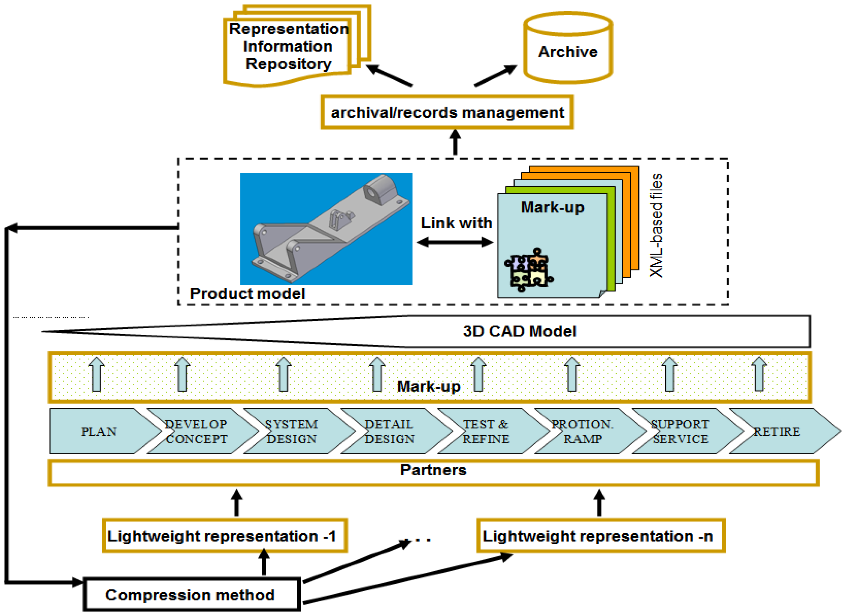
Similar to the Digital Master, various lightweight representations of product models have been developed to support information and knowledge exchange in PLM, such as PLMXML, 3D XML, X3D. A comprehensive review can be seen from Ball et al. [66]. Corresponding, there is some work that has focused on annotations on these lightweight representations. Pittarello and Faveri [67] tried to develop a general method to associate semantic information to two web standards: the X3D language and the semantic web. The approach uses scene-independent ontologies and the semantic zones that complement the role of semantic objects for giving a complete description of the environment. Ding et al. [68] proposed a strategy of integrating lightweight representations with a markup method for the whole product lifecycle. As shown in Figure 3, users across the whole product lifecycle can update related product information and share their particular expertise through ‘stand-off’ annotations using the original CAD model or related lightweight representations according to their viewpoints, purpose and security levels.
Figure 3.
Framework of lightweight representations with markup method [68].
Figure 3.
Framework of lightweight representations with markup method [68].

5.3. Annotation in collaborative design environment
Other important areas to use annotations are design reviews, collaborative product development and virtual environments. Schroeter et al. [69] developed a system named Vannotea system, which allows collaborating groups to discuss and annotate collections of high quality images, video, audio or 3D objects. The system provides the capabilities for authors to edit, search and browse annotation (e.g. personal remarks, interpretations, questions or references). Also, the annotations can be attached to whole files, segments or regions. In addition, the authors declared that the Vannotea system enables annotations to be attached either synchronously (using jabber message passing and audio/video conferencing) or asynchronously and stand-alone. Lenne et al. [70] proposed a solution including a 3D-annotation model and a knowledge model, to strengthen the communication and knowledge management in a collaborative virtual environment. The 3D-annotation model, which is based on three components: form, spatialization and metadata, is integrated into the collaborative virtual environment to assist users in communicating and maintaining a record of the engineering design process. The knowledge model is based on ontology to allow annotations to be indexed, further to support annotation retrieval. Hisarciklilar and Boujut [71] described an annotation model of digital design representations to improve actors’ communication in an asynchronous design. The proposed annotation model combines with speech act theory (SAT), which proposes a clear distinction between various levels of communication (namely locutionary, illocutionary and perlocutionary), so as to enhance the design communication through the elicitation of knowledge related to the context of design. A demonstration has been developed by authors based on a lightweight 3D representation – VRML.
5.4. Recent research direction
More recently researchers have started to look at whether annotations can be directly involve with design methodologies, like design optimizations, various Computer Aided Engineering (CAE) functions, conceptual design and product redesign. Matthews et al. [72] presents a supportive approach which allows the designer to annotate the initial CAD drawn models with the design constraints. These constraints are then maintained with the model as it evolves, this presents the opportunity to handle (optimize) the constraints when the design activity requires. Furthermore, the evolving design constraints are saved, which allow the designer to capture design history and further reuse previous design.
Vucinic et al. [73] explored to build multidisciplinary engineering environments through use of ontologies, the semantic metadata descriptors. The main objectives of the proposed method are integration of heterogeneous data sources, and enhancement of the end-users interactions with the engineering content. A prototype has been developed using XML-based software technologies, such as X3D and OWL. The proposed method is demonstrated by the combination use of FEM (Finite Element Method) and CFD (Computational Fluid Dynamics) solvers in a complex multi-physics problem FSI (Fluid Structure Interaction).
Table 3 summarises the work on applications in engineering.
| Approach | Strategy | Technique | Targets | Applications | Markup languages involved |
|---|---|---|---|---|---|
| Work by Kim and Compton, 2004 [50] | In-line | Manual | Web-based document | Document management & retrieval | Unclear |
| Work by Soo et al. 2003 [51] | In-line | Automatic | Document | Document retrieval | RDF |
| ANITA by Gardoni 2005 [52], Frank and Gardoni 2005 [53] | In-line | Manual | Document (whole or parts) | Information retrieval | XML |
| KIM by Kiryakov et al. 2004 [54] | Stand-off | Automatic | Entity | Information retrieval | RDF |
| @WEB by Hignette et al. 2008 [55] | In-line | Semi-automatic | Data tables in documents | Information retrieval | Unclear |
| Work by Elinson and Nau, 1997 [57] | In-line | N/A | Graph representation of machining features | Feature classification | Unclear |
| Work by Hoffman and Joan-Arinyo, 1998 [58] | In-line | N/A | Product model | Multiple viewpoints | Unclear |
| CAD/CAM (e.g. AutoCAD 2008, SolidEdge V19, Pro/ENGINEER, NX5, CATIA V5R13), Microstation [59,60,61,62,63,64] | In-line | Manual | CAD models | Association of information | Unclear |
| LIMMA by Ding et al. 2009 [14] | Stand-off | Manual | CAD models | Multiple viewpoints | XML |
| EPM by Ding et al. 2009 [1] | Stand-off | Manual | CAD models | Information organization and retrieval in PLM | XML |
| TaDiMa by Fiorentino et al. 2009 [65] | In-line / stand-off | Automatic | Digital Master | Marketing and design review | HTML |
| Work by Pittarello and Faveri, 2006 [67] | In-line | N/A | X3D, semantic web | Navigational support | X3D/RDF/XML |
| Work by Ding et al. 2009 [68] | Stand-off | Manual | CAD models/ Lightweight representations | Management of lifecycle product information | XML |
| Vannotea by Schroeter et al. 2006 [69] | Stand-off | Manual | Images, video, 3D object, audio | Communication in collaboration | XML |
| Work by Lenne et al. 2009 [70] | In-line | Manual | 3D object | Communication and knowledge management | Unclear |
| Work by Hisarciklilar and Boujut, 2009 [71] | Stand-off | Manual | VRML | Communication in collaboration | VRML |
| Work by Matthews et al. 2009 [72] | Stand-off | Manual / Semi-automatic | CAD models | Support of design optimisation | XML |
| Work by Vucinic et al. 2009 [73] | In-line | N/A | X3D | Multidisciplinary engineering environments | X3D/OWL |
6. Summary and discussion
Digital annotation has developed rapidly during the last two decades. Nowadays, annotation has been widely used in different digital items, including text documents, structured data (e.g. databases and tables), 2D images, 3D models and multimedia (e.g. video and audio). This paper has presented a contemporary review of the latest research into the area of annotation and its subtype, markup related to engineering design. It has shown that:
- 1)
- Annotation and markup have shown their advantages in various applications. XML, as one of most common markup languages, has been widely applied due to its characteristics, especially its extensibility, representation of semi-structure information, and support of re-organisation and multi-viewpoints. As shown in the review, the powers of XML have led to a large number of XML-based markup languages founded on various scenarios and applications, which have resulted in the problem of information interoperability when considered for future usage.
- 2)
- There are two basic types of markup methods: ‘in-line’ and ‘stand-off’. The ‘in-line’ method can be easily implemented using a text editor or a simple scripting language, and therefore it has been widely adopted, especially in document management. However, with high requirements to support multi-viewpoints and the introduction of 3D annotation, ‘stand-off’ method starts to show its potential. Although some technical issues like persistent references and maintenance of changes, have not yet been adequately solved, which hinders its applications in industry.
- 3)
- It is inspiring to see that annotations have played a key role in product development. The work on information retrieval comes not only from the engineering community, but also from computer science and IT industry. The current achievements encourage researchers to think about extending the application from document to 3D models and multimedia. Compared with document retrieval, the researches on 3D annotation started a little later, but the latest results, such as exploration of ‘stand-off’ annotation on 3D models, integration with PLM requirements and datasets, and applications in collaboration environment, have already shown their considerable impacts for industrial solutions. In addition, it can be seen that the 3D annotation is still an active area of research recently. The work on design methodology has just started. Therefore, results are still limited, but the potential for the future work is warranted. Some further research questions have already been identified: for example, how to integrate annotation techniques with current CAE supporting tools, how to combine the techniques with traditional design process and rationale capture tools, etc.
In summary, the techniques of annotation and markup have been quickly developed as a result of the advances of digital technology. The review has shown that the advantages of annotation and markup have been recognized by both academics and industry, and therefore a number of applications have been proposed for engineering design. The exciting outputs provide confidence of researchers that further potential benefits can be achieved in engineering design, though some of technique issues still need to be addressed (will be discussed in the next section).
7. Future research directions
For more extensive applications in industry, more in-depth work on annotations is necessary. The following describes suggested directions that the authors believe further work needs to focus on:
- 1)
- Persistent identification of geometry: The issue of the persistent identification of geometry, also called the ‘persistent naming problem’, was raised by Mun and Han [74]. The initial focus of the problem was how to identify the surviving entities of a pre-edit B-rep in the post-edit B-rep. Now, the persistent identification of geometry is becoming a key obstacle in translating annotations references between various 3D models formats, for example, how can annotations be shared among the users of the native CAD models and the users of the derived lightweight versions? To explore a solution, an experiment using UGS NX3 and Adobe Acrobat 3D 8.1 has been carried out [75]. The results show that the face labels in the original CAD model did survive during its translation to PRC format in PDF, meaning that all the faces of the product model could be persistently identified; it is therefore possible, at least in principle, that features based on a specific viewpoint could be constructed as combinations of the faces of the model. Correspondingly, if an original CAD model remains constant, the annotations could also survive within both the CAD model and the lightweight formats. Although the results are inspiring, there is a risk that the linkage between the CAD model and the annotation may be lost when the entity referred to is deleted in the CAD model. Obviously, an intensive exploration on the representations of 3D models and 3D annotation techniques needs to be carried out between academics, standards community and commercial industry.
- 2)
- Semi-automatic/automatic information capture tools: Most applications of annotation are still user-intervention-based. That is, it needs manual input. If the users forget to update their changes or neglect to retrieve the information to annotate, the annotation systems cannot work well and some of important information will be lost. Thus, dedicated information capture tools is worth exploring to support semi-automatic or automatic annotations. Some efforts on automatic information capture are being carried out by both academics and software industry. For example, the Simulation Process Studio (SPS) with UGS NX 3 Simulation [76] provides a palette of standard steps for users to drag and drop into the process with connecting lines defining the flow. The steps can then be saved as an XML file and made available to the standard Unigraphics NX application. Obviously, the results are still limited and more efforts are needed.
- 3)
- Enhancement of support for development methodology: As reviewed, recently, more and more researchers are transferring their attention to directly support design methodology, but the outputs of the work are still not enough. Further fundamental researches are required, including how to use annotation to help the capture of the design process, retrieval of rationale behind, and support of CAE tools. This would highlight that the work could be more meaningful if it integrates with latest design methodology and changes of working way (e.g. distributed cooperation). The latest work performed by Ding et al. [77] presented a general component-based approach to making records of transactional for design activities. In the proposed method, the activities are individually recorded in XML-based format, which can be assembled, tailored and transformed in different ways by XSL/XSLT. Therefore, it shifts design records to design reuse.
Acknowledgements
The work reported in this paper has been conducted as part of the EPSRC funded Innovative Manufacturing Research Centre (IDMRC) at the University of Bath. The authors gratefully express their thanks for the advice and support of all concerned.
References
- Ding, L.; Matthews, J.; McMahon, C.A.; Mullineux, G. An Information Support Approach for Machine Design & Build Companies. Concurrent Eng. – Res. A. 2009, 17, 103–109. [Google Scholar] [CrossRef]
- Patel, M.; Ball, A.; Ding, L. Strategies for the Curation of CAD Engineering Models. Int. J. Digital Curation 2009, 4, 84–97. [Google Scholar] [CrossRef] [Green Version]
- Feilden, B.R. Engineering Design: Report of Royal Commission, 2nd Ed. ed; HMSO: London, UK, 1963. [Google Scholar]
- NX. http://www.plm.automation.siemens.com/en_gb/products/nx/index.shtml (accessed 10 February, 2010).
- AutoCAD. http://usa.autodesk.com/ (accessed 10 February, 2010).
- Pro/Engineer. http://www.ptc.com/products/proengineer/ (accessed 10 February, 2010).
- Clarkson, P.J.; Hamilton, J.R. Signposting, a Parameter-driven Task-based Model of the Design Process. Res Eng Des 2000, 12, 18–38. [Google Scholar] [CrossRef]
- Ryu, K.; Yücesan, E. CPM: A Collaborative Process Modeling for Cooperative Manufacturers. Adv. Eng. Inform. 2007, 21, 231–239. [Google Scholar] [CrossRef]
- Browning, T.R.; Fricke, E.; Negele, H. Key Concepts in Modeling Product Development Processes. Syst. Eng. 2006, 9, 104–128. [Google Scholar] [CrossRef]
- Bracewell, R.H.; Wallace, K.M. A Tool for Capturing Design Rationale. In Proceedings of the 14th International Conference on Engineering Design (ICED’03), Stockholm, Sweden, August 2003; pp. 185–186.
- Regli, W.C.; Hu, X.; Atwood, M.; Sun, W. A Survey of Design Rationale Systems: Approaches, Representation, Capture and Retrieval. Eng. Comput. 2000, 16, 209–235. [Google Scholar] [CrossRef]
- Li, W. D.; Qiu, Z. M. State-of-the-Art Technologies and Methodologies for Collaborative Product Development Systems. Int. J. Prod. Res. 2006, 44, 2525–2559. [Google Scholar] [CrossRef]
- Van der Aalst, W.M.P. Exploring the CSCW Spectrum using Process Mining. Adv. Eng. Inform. 2007, 21, 191–199. [Google Scholar] [CrossRef]
- Ding, L.; Davies, D.; McMahon, C.A. The Integration of Lightweight Representation and Annotation for Collaborative Design Representation. Res. Eng. Des. 2009, 19, 223–238. [Google Scholar] [CrossRef]
- Khare, R.; Rifkin, A. The Origin of Document Species. Comput. Networks ISDN 1998, 30, 389–397. [Google Scholar] [CrossRef]
- Coombs, J.H.; Renear, A.H.; DeRose, S.J. Mark-up Systems and the Future of Scholarly Text Processing. Commun. ACM 1987, 30, 933–947. [Google Scholar] [CrossRef]
- Liu, S.; McMahon, C.A.; Culley, S.J. A Review of Structured Document Retrieval (SDR) Technology to Improve Information Access Performance in Engineering Document Management. Comput. Ind. 2008, 59, 3–16. [Google Scholar] [CrossRef]
- Johnston, P. What you have always wanted to know that about SGML, HTML and XML but were afraid to ask: why mark-up matters. In Presented at Society of Archivists’ Diploma in Archive Administration Seminar, Edinburgh, UK, November 1998.
- Goldfarb, C. The SGML Handbook; Rubinsky, Y., Ed.; Clarendon Press: Oxford, UK, 1990. [Google Scholar]
- Brecher, C.; Vitr, M.; Wolf, J. Closed-loop CAPP/CAM/CNC Process Chain based on STEP and STEP-NC Inspection Tasks. Int. J. of Computer Integr. Manuf. 2006, 19, 570–580. [Google Scholar] [CrossRef]
- Lee, C.K.M.; Ho, G.T.S.; Lau, H.C.W.; Yu, K.M. A Dynamic Information Schema for Supporting Product Lifecycle Management. Expert Syst. Appl. 2006, 31, 30–40. [Google Scholar] [CrossRef]
- Kang, J.; Lee, J.K. Rule Identification from Web Pages by the XRML Approach. Decis. Support Syst. 2005, 41, 205–227. [Google Scholar] [CrossRef]
- Chung, H.S.; Lee, Y. MCML: Motion Capture Mark-up Language for Integration of Heterogeneous Motion Capture Data. Comp. Stand. Inter. 2004, 26, 113–130. [Google Scholar] [CrossRef]
- Wang, Y.; Ajoku, P.N.; Brustoloni, J.C.; Nnaji, B.Q. Intellectual Property Protection in Collaborative Design through Lean Information Modelling and Sharing. J. Comput. Inf. Sci. Eng. 2006, 6, 149–159. [Google Scholar] [CrossRef]
- Anwar, N.; Kanok-Nukulchai, W.; Batanov, D.N. Component-based, Information Oriented 3D Structural Engineering Applications. J. Comput. Civil Eng. 2005, 19, 45–57. [Google Scholar] [CrossRef]
- Swindells, N. Communication Materials Information: Product Data Technology for Materials. Int. Mater. Rev. 2002, 47, 31–46. [Google Scholar] [CrossRef]
- PGML, Precision Graphics Mark-up Language. www.w3.org/TR/1998/NOTE-PGML-19980410 (accessed 10 February, 2010).
- X3D, eXtensible 3D. www.web3d.org (accessed 10 February, 2010).
- Kim, C.Y.; Kim, N.; Kim, Y.; Kang, S.H.; O’Grady, P. Distributed Concurrent Engineering: Internet-based Interactive 3-D Dynamic Browsing and Mark-up of STEP Data. Concurrent Eng. – Res. A. 1998, 6, 53–70. [Google Scholar] [CrossRef]
- Li, W.D. A Web-based Service for Distributed Process Planning Optimisation. Comput. Ind. 2005, 56, 272–288. [Google Scholar] [CrossRef]
- Versprille, K. Dassault Systèmes’ Strategic Initiative: 3D XML for Sharing Product Information. In Presented at Technology Trends in PLM, Collaborative Product Development Associates, Stamford, CT, USA, July 2005.
- Open product lifecycle data sharing using XML, Write paper: PLM XML. http://www.plm.automation.siemens.com/en_us/Images/plm%20xml%20wp%20W%203_tcm1023-11521.pdf (accessed 10 February, 2010).
- Resource Description Framework (RDF). http://www.w3.org/RDF/ (accessed 10 February, 2010).
- OWL Web Ontology Language Overview. http://www.w3.org/TR/owl-features/ (accessed 10 February, 2010).
- Commerce XML Resources. http://www.cxml.org/ (accessed 10 February, 2010).
- SOAP, Simple Object Access Protocol. http://www.w3.org/2000/xp/Group/ (accessed 10 February, 2010).
- WSDL, Web Service Description Language. http://www.w3.org/2002/ws/desc/ (accessed 10 February, 2010).
- XML-RPC, XML—Remote Procedure Calls. http://www.xml-rpc.net/ (accessed 10 February, 2010).
- Umar, A. The Emerging Role of the Web for Enterprise Applications and ASPs. Proc. IEEE 2004, 92, 1420–1438. [Google Scholar] [CrossRef]
- Bussler, C. Semantic Web Services—Fundamentals and Advanced Topics. Lect. Notes Comput. Sci. 2004, 3263, 1–8. [Google Scholar]
- The Text Encoding Initiative (TEI) Consortium, Stand-off Markup. http://www.tei-c.org/Activities/SO/sow06.xml?style=printable (accessed 10 February, 2010).
- Thompson, H.S.; McKelvie, D. Hyperlink Semantics for Standoff Markup of Read-only Documents. In Proceedings of SGML Europe’97: The next decade – Pushing the Envelope, Barcelona, Spain, 1997; pp. 227–229.
- Davies, D.; McMahon, C.A. Multiple Viewpoint Design Modelling through Semantic Markup. In Proceedings of IDETC/CIE 2006, ASME 2006 International Design Engineering Technical Conferences and Computers and Information in Engineering Conference, Philadelphia, Pennsylvania, USA, 2006.
- Alink, W. XIRAF: An XML-IR Approach to Digital Forensics. Master’s thesis, University of Twente, Enschede, The Netherlands, 2005. [Google Scholar]
- Taghva, K.; Condit, A.; Borsack, J. Autotag: A Tool for Creating Structured Document Collections from Printed Materials. http://www.isri.unlv.edu/publications/isripub/Taghva98b.pdf (accessed 10 February, 2010).
- Akhtar, S.; Reilly, R.G.; Dunnion, J. Auto-tagging of Text Documents into XML. Lect. Notes Comput. Sci. 2003, 2807, 20–26. [Google Scholar]
- Cui, H. ARTT: A General Approach to Automatic Mark-up of Taxonomic Descriptions with XML. http://www.cais-acsi.ca/proceedings/2005/cui_2005.pdf (accessed 10 February, 2010).
- Feldman, R.; Rosenfeld, B.; Fresko, M. TEG—a Hybrid Approach to Information Extraction. Know. Inf. Sys. 2006, 9, 1–18. [Google Scholar] [CrossRef]
- Vargas-Vera, M.; Motta, E.; Domingue, J.; Lanzoni, M.; Stutt, A.; Ciravegna, F. MnM: Ontology Driven Semi-automatic and Automatic Support for Semantic Mark-up. Lect. Notes Comput. Sci. 2002, 2473, 379–391. [Google Scholar] [CrossRef]
- Kim, M.; Compton, P. Evolutionary Document Management and Retrieval for Specialized Domains on the Web. Int. J. Hum.-Comput. Stud. 2004, 60, 201–241. [Google Scholar] [CrossRef]
- Soo, V.W.; Lee, C.Y.; Li, C.C.; Chen, S.L.; Chen, C.C. Automated Semantic Annotation and Retrieval Based on Sharable Ontology and Case-based Learning Techniques. In Proceedings of the 3rd ACM/IEEE-CS Joint Conference on Digital Libraries (JCDL’ 2003), Houston, TX, USA, May 2003; pp. 61–72.
- Gardoni, M. Concurrent Engineering in Research Projects to Support Information Content Management in a Collective Way. Concurrent Eng. – Res. A. 2005, 13, 135. [Google Scholar] [CrossRef]
- Frank, C.; Gardoni, M. Information Content Management with Shared Ontologies—at Corporate Research Centre of EADS. Int. J. Inf. Manage. 2005, 25, 55–70. [Google Scholar] [CrossRef]
- Kiryakov, A.; Popov, B.; Ognyanoff, D.; Manov, D.; Goranov, K.M. Semantic Annotation, Indexing, and Retrieval. J. Web Semantics 2004, 2, 49–79. [Google Scholar] [CrossRef]
- Hignette, G.; Buche, P.; Couvert, O.; Dibie-Barthélemy, J.; Doussot, D.; Haemmerlé, O.; Mettler, E.; Soler, L. Semantic Annotation of Web Data Applied to Risk in Food. Int. J. Food Microbiol. 2008, 128, 174–180. [Google Scholar] [CrossRef]
- American Society of Mechanical Engineers. An American National Standard: digital product definition data practices; ASME: New York, USA, 2003. [Google Scholar]
- Elinson, A.; Nau, D. S.; Regli, W. C. Feature-based Similarity Assessment of Solid Models. In Proceedings of the Fourth ACM Symposium on Solid Modeling and Applications, Atlanta, Georgia, USA, 1997; pp. 297–310.
- Hoffmann, C. M.; Joan-Arinyo, R. CAD and the Product Master Model. Comput.-Aided Des. 1998, 30, 905–918. [Google Scholar] [CrossRef]
- Fane, B. Autodesk AutoCAD 2008 (Cadalyst Labs Review) – New annotations are the name of the game. Cadalyst. April 2007. http://www.cadalyst.com/general-software/autodesk-autocad-2008-cadalyst-labs-review-6061 (accessed 10 February, 2010).
- Cohn, D. New Enhancements in Solid Edge. CADCAMNet. June 2006. http://www.plm.automation.siemens.com/en_us/Images/cadcamnet_solidedge_v19review_tcm1023-22637.pdf (accessed 10 February, 2010).
- Rowe, J. Cadalyst Labs Review: PTC Pro/ENGINEER Wildfire 3 Workflow efficiency and productivity take center stage. Cadalyst. September 2006. http://www.cadalyst.com/manufacturing/cadalyst-labs-review-ptc-proengineer-wildfire-3-10834 (accessed 10 February, 2010).
- Rowe, J. Cadalyst Labs Review: NX5, Part2 – Enhancements in software architecture enable major improvements in assemblies, visualization, and drawings. Cadalyst. December 2007. http://manufacturing.cadalyst.com/manufacturing/article/articleDetail.jsp?id=475124 (accessed 10 February, 2010).
- CATIA - 3D Functional Tolerancing and Annotations, 2(FTA), CATIA V5R19. http://www.catia.cz/fileadmin/Pictures_Menu/Catia/Catia_V5/Mechanical_Domain/pdf/FTA.pdf (accessed 10 February, 2010).
- Anderson, A. Microstation V8 – An Introduction to Computer Aided Design; Schroff Development Corporation: Mission, KS, USA, 2002. [Google Scholar]
- Fiorentino, M.; Monno, G.; Uva, A. E. Tangible Digital Master for Product Lifecycle Management in Augmented Reality. Int. J. Interact. Des. Manuf. 2009, 3, 121–129. [Google Scholar] [CrossRef]
- Ball, A.; Ding, L.; Patel, M. An Approach to Accessing Product Data across System and Software Revisions. Adv. Eng. Inform. 2008, 22, 222–235. [Google Scholar] [CrossRef]
- Pittarello, F.; Faveri, A.D. Semantic Description of 3D Environments : a Proposal Based on Web Standards. In Proceedings of the eleventh International Conference on 3D Web Technology, Columbia, Maryland, USA, 2006; pp. 85–95.
- Ding, L.; Ball, A.; Matthews, J.; McMahon, C.A.; Patel, M. Annotation of Lightweight Formats for Long-term Product Representations. Int. J. of Computer Integr. Manuf. 2009, 22, 1037–1053. [Google Scholar] [CrossRef] [Green Version]
- Schroeter, R.; Hunter, J.; Guerin, J.; Khan, I.; Henderson, M. A Synchronous Multimedia Annotation System for Secure Collaboratories. In Proceedings of the Second IEEE International Conference on e-Science and Grid Computing, Piscataway, USA, 2006; p. 41.
- Lenne, D.; Thouvenin, I.; Aubry, S. Supporting Design with 3D-annotations in a Collaborative Virtual Environment. Res. Eng. Des. 2009, 20, 149–155. [Google Scholar] [CrossRef]
- Hisarciklilar, O.; Boujut, J.F. An annotation model to reduce ambiguity in design communication. Res. Eng. Des. 2009, 20, 171–184. [Google Scholar] [CrossRef]
- Matthews, J.; Ding, L.; Feldman, J.; Mullineux, G. The Maintenance and Handling of Constraints in Machine Design. In Proceedings of the ASME 2009 International Design Engineering Technical Conferences & Computers and Information in Engineering Conference, IDETC/CIE 2009, San Diego, California, USA, August 30 – September 2, 2009. 10 pages on CD. ISBN 978-0-7918-3856-3.
- Vucinic, D.; Pesut, M.; Jovic, F.; Lacor, C. Exploring Ontology-based Approach for Facilitate Integration of Multi-physics and Visualization for Numerical Models. In Proceedings of the ASME 2009 International Design Engineering Technical Conferences & Computers and Information in Engineering Conference, IDETC/CIE 2009, San Diego, California, USA, August 30 – September 2, 2009. 10 pages on CD. ISBN 978-0-7918-3856-3.
- Mun, D.; Han, S. Identification of Topological Entities and Naming Mapping for Parametric CAD Model Exchanges. Int. J. CAD/CAM 2005, 5, 69–82. [Google Scholar]
- Ding, L.; Ball, A.; Patel, M.; Matthews, J.; Mullineux, G. Strategies for the Collaborative Use of CAD Product Models. In Proceedings of the 17th International Conference on Engineering Design (ICED'09), Stanford, CA, USA, August 2009; pp. 123–134, ISBN 978-1-904670-12-4.
- Simulation Process Studio. http://newsletter.plmworld.org/archive/Vol3No3/Ogilvie.php (accessed10 February, 2010).
- Ding, L.; Giess, M.; Goh, Y.M.; McMahon, C.A.; Thangarajah, U. Component-based Records: a Novel Method to Record Transaction Design Work. Adv. Eng. Inform. 2009, 23, 332–347. [Google Scholar] [CrossRef] [Green Version]
© 2010 by the authors; licensee Molecular Diversity Preservation International, Basel, Switzerland. This article is an open access article distributed under the terms and conditions of the Creative Commons Attribution license (http://creativecommons.org/licenses/by/3.0/).
Share and Cite
MDPI and ACS Style
Ding, L.; Liu, S. Markup in Engineering Design: A Discourse. Future Internet 2010, 2, 74-95. https://doi.org/10.3390/fi2010074
AMA Style
Ding L, Liu S. Markup in Engineering Design: A Discourse. Future Internet. 2010; 2(1):74-95. https://doi.org/10.3390/fi2010074
Chicago/Turabian StyleDing, Lian, and Shaofeng Liu. 2010. "Markup in Engineering Design: A Discourse" Future Internet 2, no. 1: 74-95. https://doi.org/10.3390/fi2010074