Implementing Value Added Applications in Next Generation Networks

Abstract
:
1. Introduction

- (1)
- Weather Forecast Service provides local weather, the weather forecast next week, international weather, satellite images, video forecasts, and so on. The service also offers special weather reports for, e.g., typhoons, low temperature, heavy rain, and earthquakes. In this service, users can set their favorite cities or obtain weather information of their current locations through the Location Based Service (LBS).
- (2)
- Dining Information Service provides the menu/prices of dishes of a restaurant. The food description service allows a user to query neighborhood restaurant information, restaurant addresses and phone numbers.
- (3)
- Music Video (MV) Information Service allows a user to browse movie trailers and download music.
- (4)
- Living Information Service provides Lotto winning numbers and uniform-invoice prize winning numbers inquiries.
- (5)
- Traffic Information Service provides immediate road status, Department of Rapid Transit System (DRTS) road maps, and timetables for airlines, Taiwan High Speed Rail (THSR), Taiwan Railways, etc.
- (6)
- Health Care Information Service provides neighborhood hospital information inquiry.
- (7)
- My Service provides user billing information.
2. The MMAS/IPTV-CS Architecture and the Registration Procedure
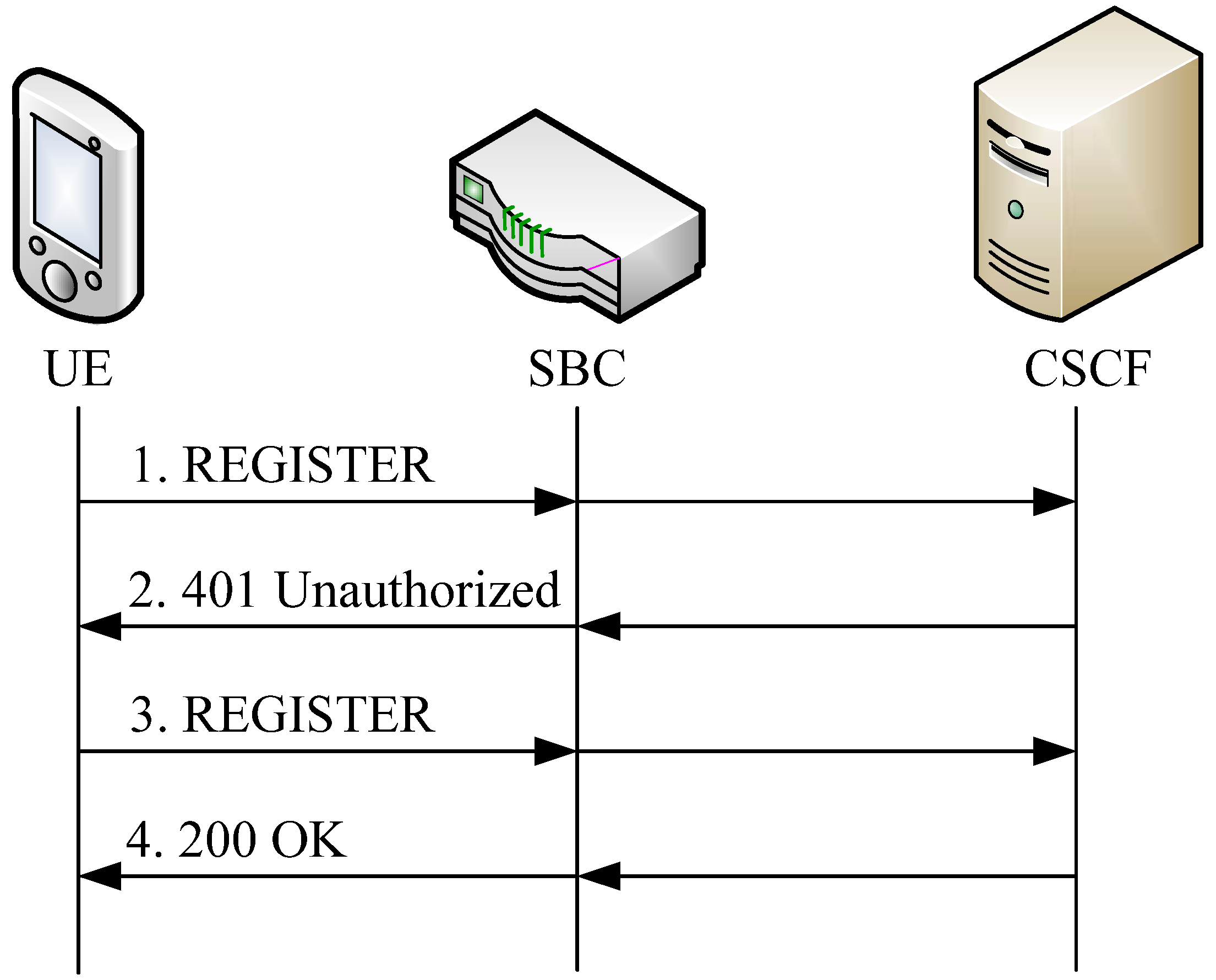
- Step 1:
- The UE (with the phone number +886233111111) sends a SIP REGISTER request to the CSCF with the domain name ims1.cht.com.tw. Therefore, the Request-URI of the SIP REGISTER is <sip: [email protected]>.
- Step 2:
- When the CSCF receives this request, it selects the authentication vector [8] to challenge the UE. Then the CSCF sends the authentication vector to the UE through 401 Unauthorized message.
- Step 3:
- After receiving 401 Unauthorized message, the UE produces an authentication response, and sends it back to the CSCF through a SIP REGISTER message.
- Step 4:
- The CSCF compares the received response with the expected response. If they match, then the authentication is successful. The CSCF replies a positive SIP 200 OK response to the UE.

3. Message Flow for Location Information
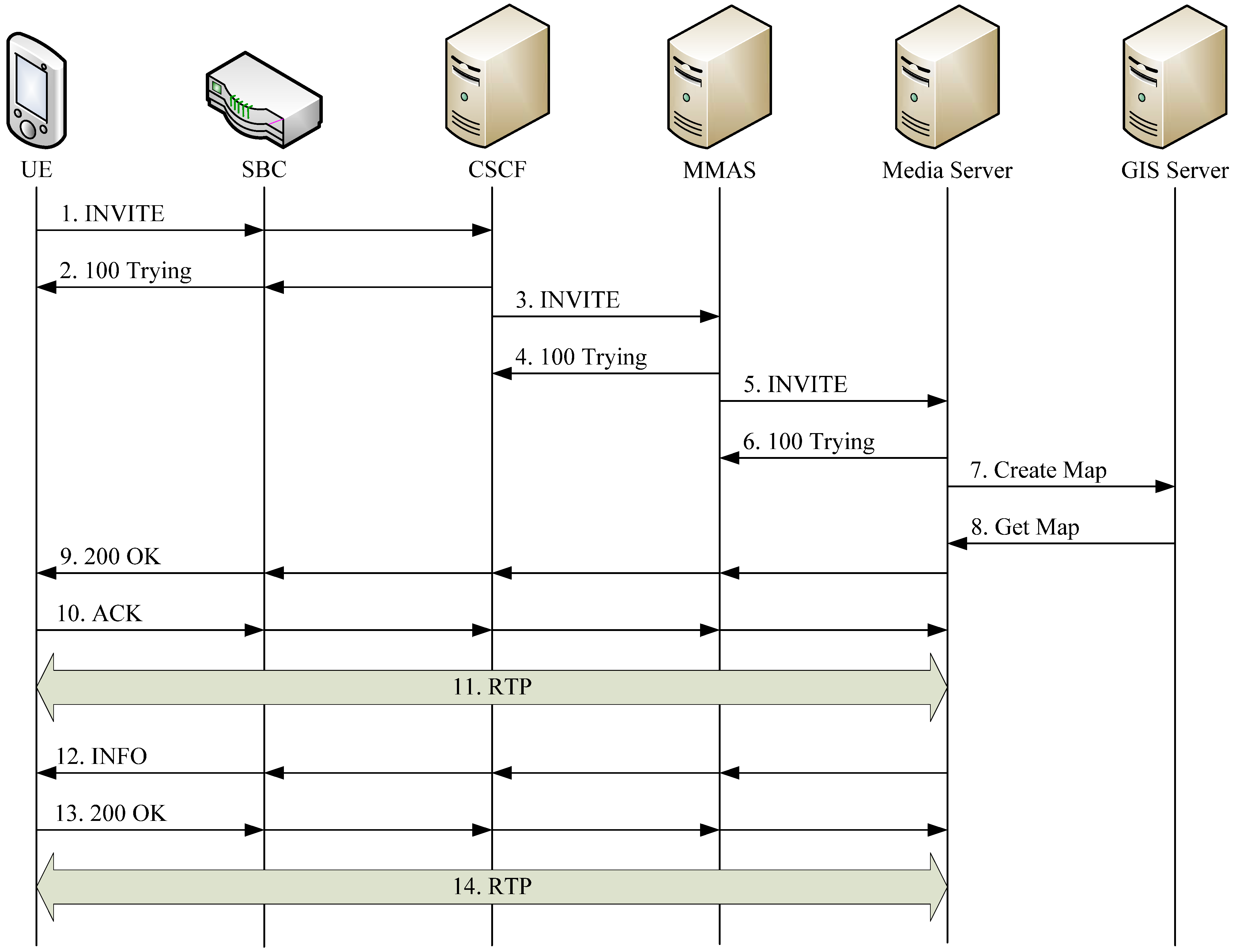
- Step 1:
- The UE sends a SIP INVITE request to the CSCF. The Request-URI is <sip:[email protected]>. The Session Description Protocol (SDP) [9] of this request specifies UE’s audio and video formats (e.g., the voice codec is AMRnb, the audio Real-time Transport Protocol (RTP) port is 17946, the video codec is H263, Common Intermediate Format (CIF) (352 x 288) resolution, and the video RTP port is 42360). The restaurant name is indicated in SDP session information field.
- Step 2:
- When the CSCF receives this SIP INVITE request, it replies a SIP 100 Trying response to UE to indicate that the setup procedure is in progress.
- Step 3:
- In parallel with Step 2, the CSCF uses 1270181 to retrieve the MMAS Server’s IP address from the routing table, and forwards the SIP INVITE request to this IP address.
- Step 4:
- If the service access number 1270181 (retrieved from the Request-URI of the INVITE) is found in the service configuration table, the MMAS Server replies the SIP 100 Trying response to inform the CSCF that the request is being handled.
- Step 5:
- The MMAS Server sends SIP INVITE to the Media Server to execute service script 1270181.
- Step 6:
- The Media Server replies 100 Trying response and starts a thread for this service with the following command:Creation of ExecBox id:5 pid:14473 userid:0 directory:'/home/ivr/1270181' and the script 1270181 located at directory /home/ivr/ is executed.
- Step 7:
- The script 1270181 instructs the GIS Server to provide the electronic map by issuing the command http://map.cht.com.tw/IntegratedMapService/GetAPI.aspx?key=xxxx, setCenter (new CLatLng(X, Y), 9)), where map.cht.com.tw is the GIS Server’s domain name, IntegratedMapService is the directory of the map service functions, and GetAPI.aspx?key=xxxx instructs the GIS Server to perform the authentication procedure with key xxxx. Function setCenter(new CLatLng(X, Y), 9) specifies the restaurant geographic coordinate (X, Y) translated from the restaurant name by the Media Server, and the radius 900 meters of the map to be retrieved.
- Step 8:
- If the request is authorized, the GIS Server copies the map picture and sends it back to the Media Server.
- Step 9:
- In parallel with Step 7, the Media Server replies the SIP 200 OK with the SDP (i.e., the negotiated audio and video formats) to the UE through the MMAS and the CSCF.
- Step 10:
- The UE sends the SIP ACK to the Media Server.
- Step 11:
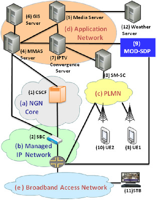
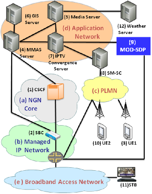
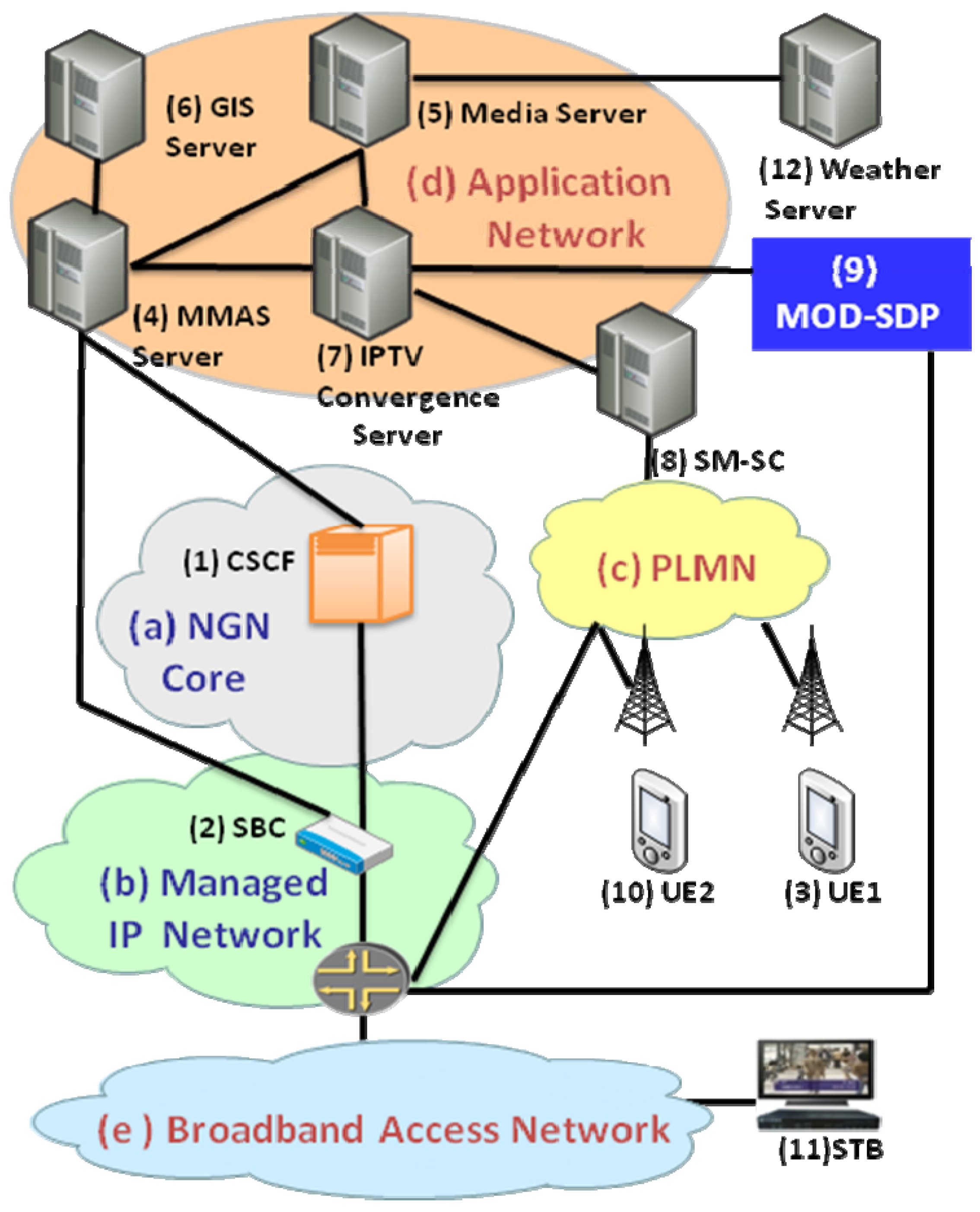
- At this point, the RTP session is established, and the requested map is delivered from the Media Server to the UE through path (5)-(2)-(c)-(3) in Figure 1.
- Step 12:
- Besides the RTP connection, the Media Server will also provide touch screen information to the UE. This information provides the grid location translation to Dual Tone Multi-Frequency (DTMF) digits. For example,<dtmf len="2" value="*1"/> <grid x1="123",y1="456",w1="24",h1="3"/> means that when the user presses the screen area of width 24 and height 3 at the coordinate (123, 456), the UE will generates two DTMF digits *1. The Media Server sends the touch screen information to the UE through SIP INFO message.
- Step 13:
- The UE replies the 200 OK to the MMAS Server. At this point, the user can appropriately touch the screen.
- Step 14:
- When the user touches the screen (e.g., he/she wants to see the menu of this restaurant), the UE will sends the corresponding DTMF digits to the Media Server through the RTP connection [10]. The Media Server then sends the new screen to the user based on the DTMF signals.

4. Weather Forecast Service
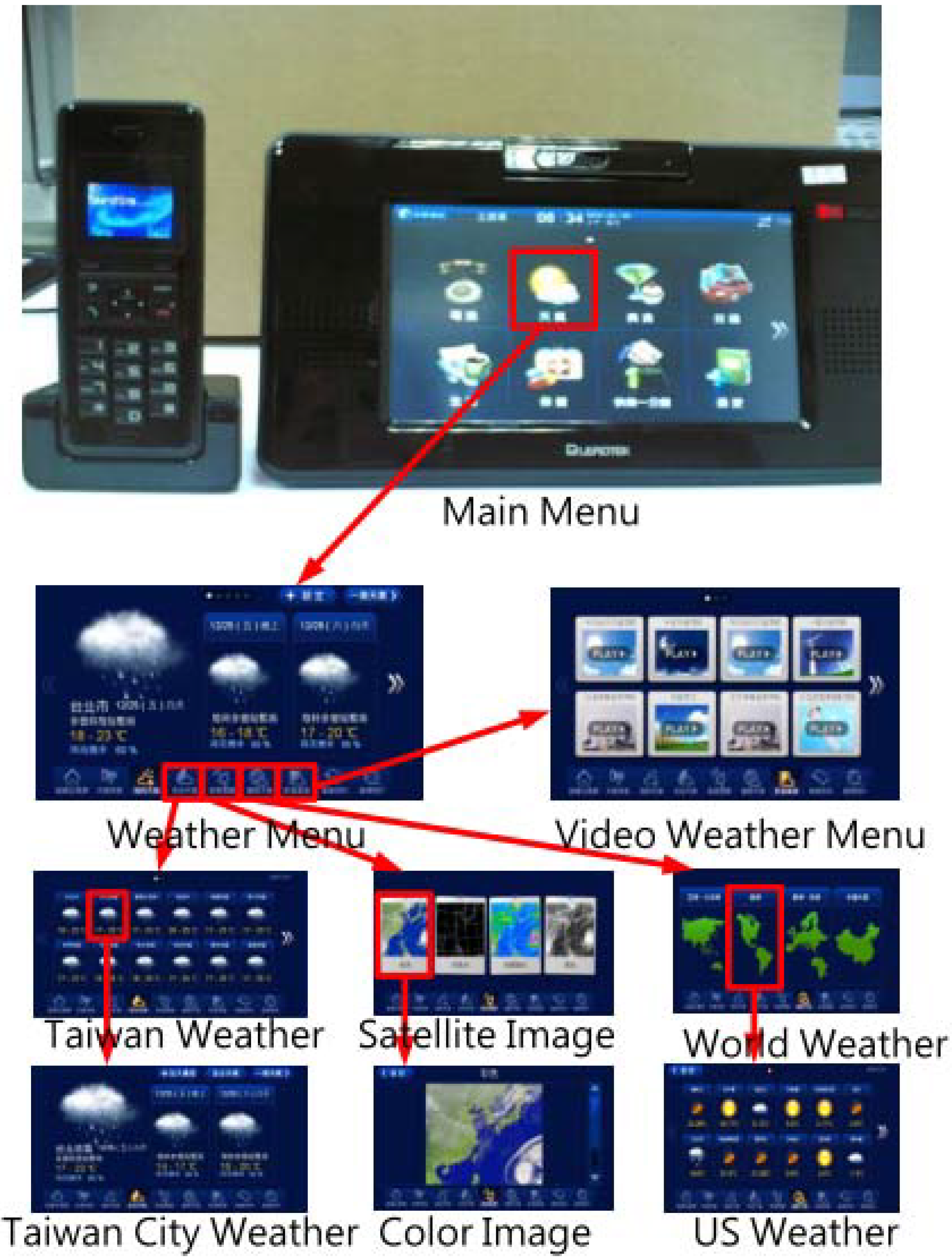
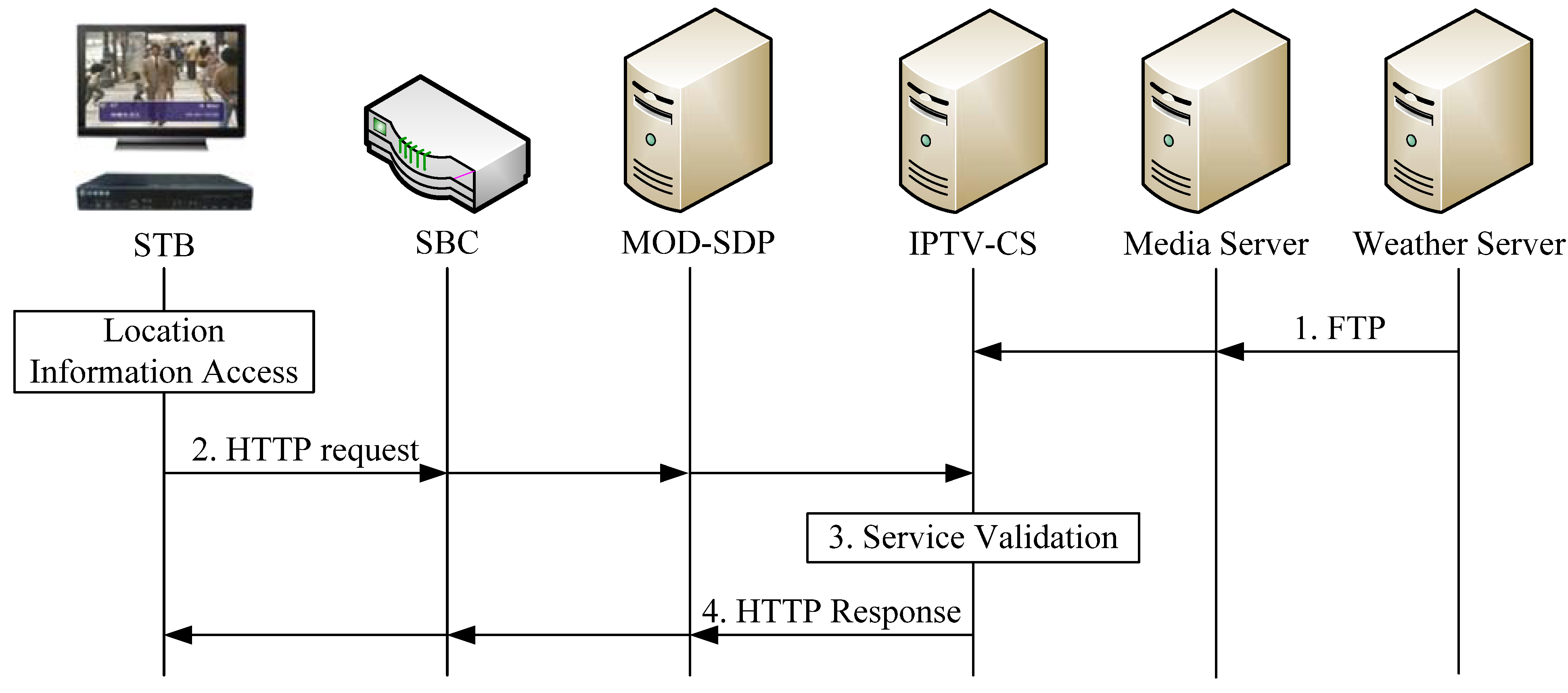
- Step 1:
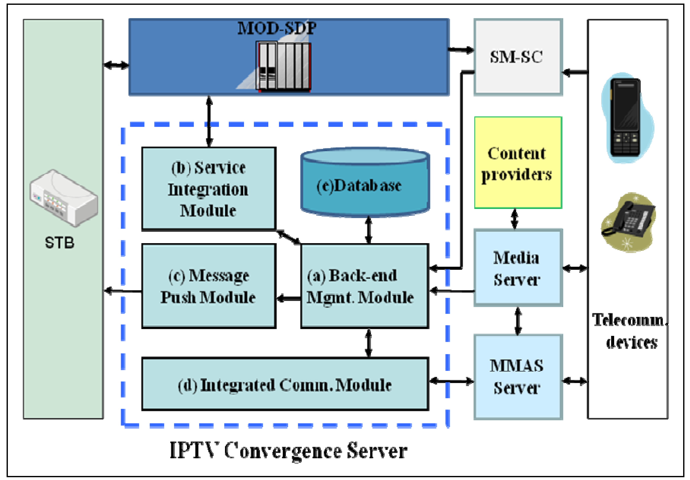
- The Central Weather Bureau (Transportation Bureau) periodically sends the weather/traffic information to the Media Server through FTP. The Media Server then forwards the information to the IPTV-CS. The BMM parses the received information and stores the results into the database [Figure 2 (e)].
- Step 2:
- To access the weather information, the browser on the STB first access the location information described in Section 3, and then sends an HTTP request to the MOD-SDP (if MOD-SDP is equipped with SIP, then the following message exchange can also be implemented by SIP). The URI of the HTTP request iswhere cs_ip and port_no are the IP address and port number of the IPTV-CS, respectively. The parameter “black” is an encrypted string containing the IP address and the identification number of the originating STB, the customer ID, and the time stamp. Function WeatherServlet is located at directory weather/, which instructs the IPTV-CS to execute the user’s request. “other_parameters” specify area, time and data type (text, image, video, or mixed data) of the weather information to be retrieved.
- Step 3:
- Upon receipt of the HTTP request, the IPTV-CS decrypts the “black” parameter by Data Encryption Standard (DES) or DES3 to authorize the request. Specifically, it queries the database [Figure 2 (e)] to obtain the subscriber’s data and compare them with the decrypted customer ID and IP address of the STB.
- Step 4:
- The IPTV-CS retrieves the required weather/traffic content including texts and images from its database, and uses them to create the web pages for the ANT Fresco or Firefox browser according to the STB type. The HTTP response with the content (web page) is returned to the STB through the MOD-SDP, and the weather/traffic information is displayed on the TV screen.

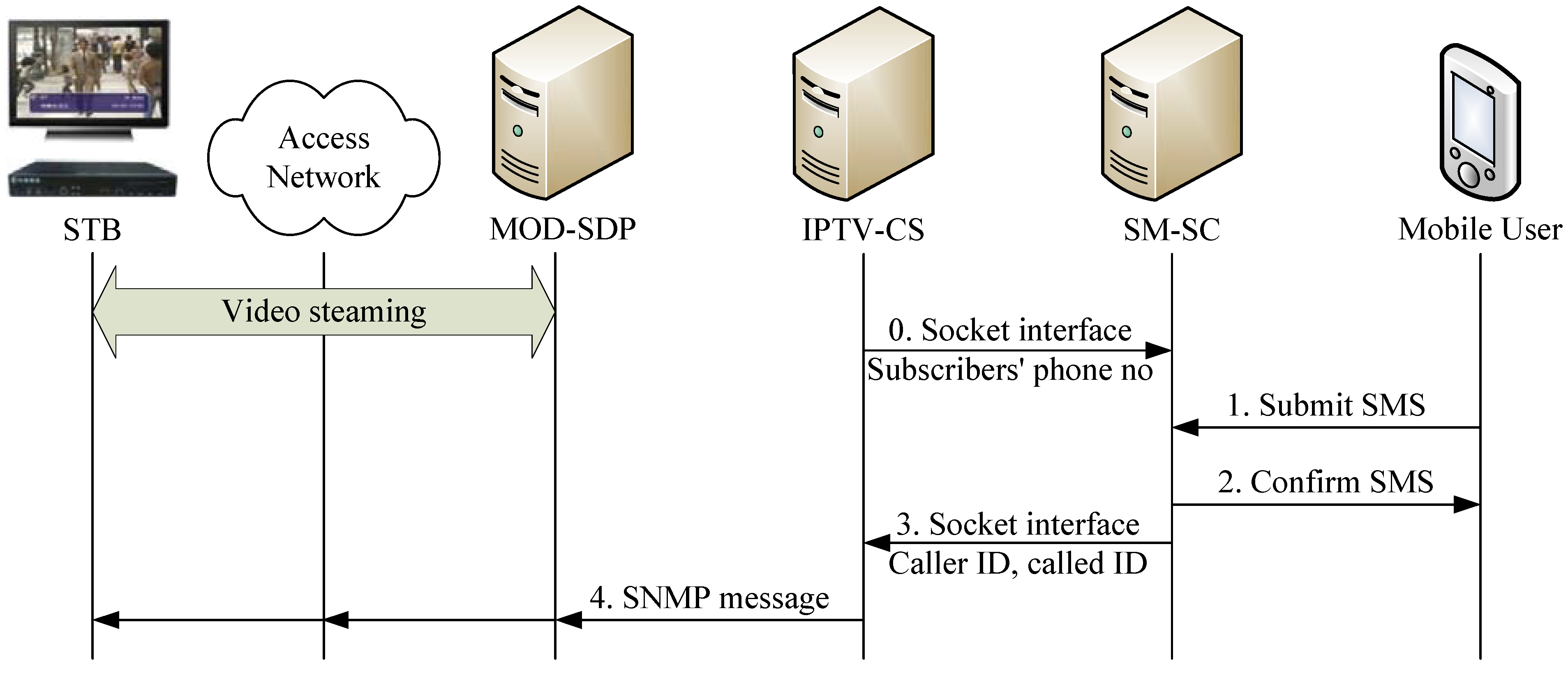
5. SMS on Screen
- Step 1:
- The short message is first delivered to the SM-SC through the GSM-MAP protocol [11].
- Step 2:
- The SM-SC confirms UE2 the receipt of this short message, and decodes it [12] to retrieve the called ID.
- Step 3:
- If this phone number is found in its MOD user database, the SM-SC forwards the message to the IPTV-CS through the SOCKET interface. This SOCKET message contains the calling ID, the called ID and the message content.
- Step 4:
- The IPTV-CS encapsulated the short message in an SNMP message sent to the target STB [(11) in Figure 1]:snmpset–c private–v 2c [STB IP] [OID] “[text]:this is a short message from 0928123456 [xywh]:50,50,400,80[timeout]:300”where private is the SNMP community name, STP_IP and OID are the IP address and the object identifier of the target STB, text is the tag for the message, xywh is the tag for the position and size of the message window, and timeout is the elapsed time to display the message on the TV screen.
6. TV Shopping/Food Ordering
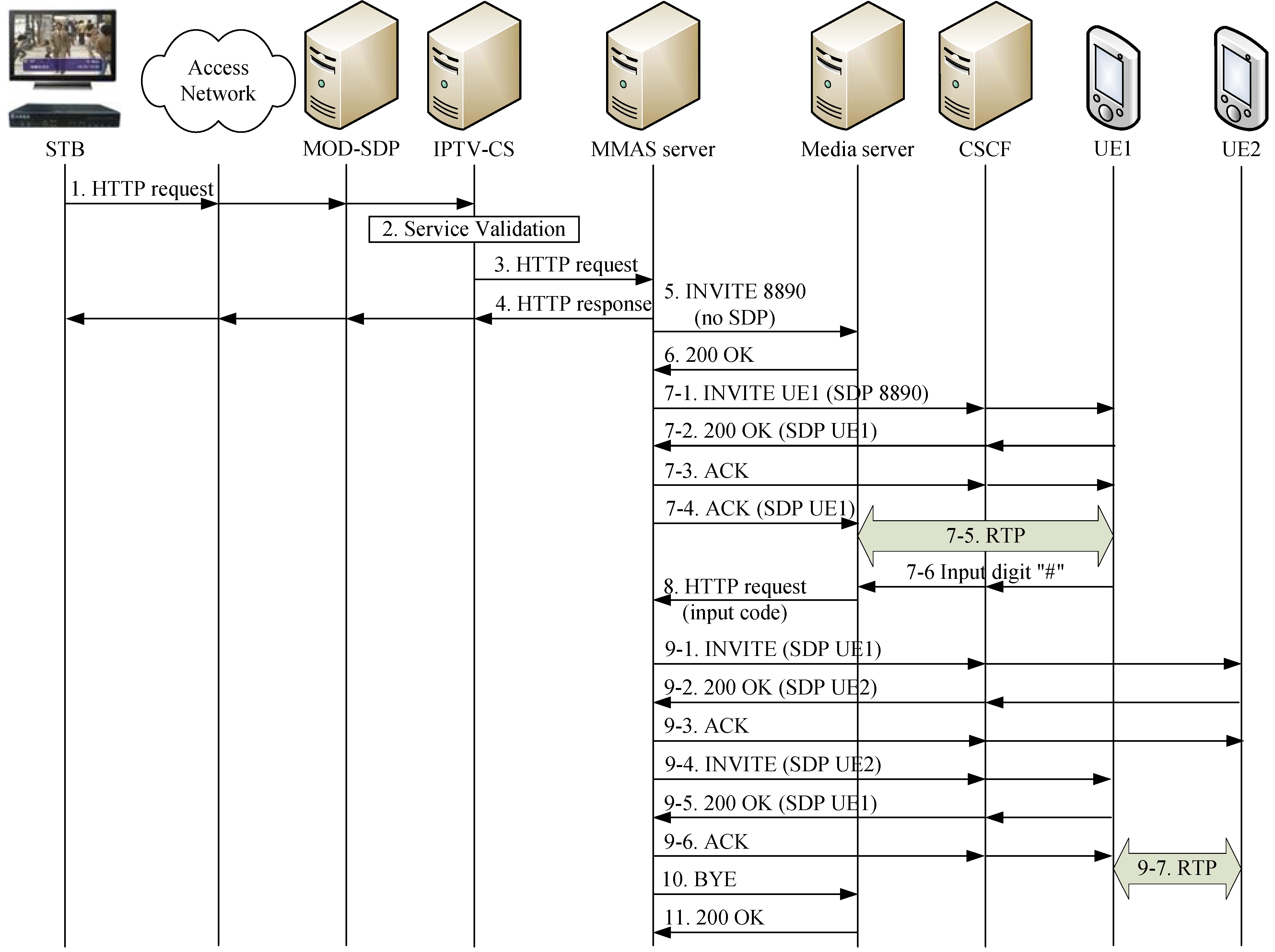
- Step 1:
- To purchase a product, UE1 selects this product shown on the TV screen by pressing the button of the remote controller. Then the browser on the STB sends an HTTP request to the MOD-SDP. The URI of the HTTP request iswhere cs_ip:port_no are the IP address/port number of the IPTV-CS, item_id indicates the merchandise the subscriber wants to order, black specifies the calling ID (i.e., the phone number of UE1), and the script MakeCallServlet under the directory IMS/ instructs the IPTV-CS to perform the Third Party Call Control (TPCC) between the MOD user (UE 1) and the vendor (UE 2). The MOD-SDP forwards the message to the IPTV-CS for the authorization procedure.
- Step 2:
- The authorization procedure is similar to Step 3 in Figure 6, and the details are omitted.

- Step 3:
- After authorization, the IPTV-CS uses item_id to retrieve the called ID (the phone number of UE2) from its product database. Then the IPTV-CS sends the HTTP request to the MMAS Server with the following URI:where mmas_ip:port_no are the IP address and port number of the MMAS Server, and the script dotpcc.jsp in directory TPCC/ instructs the MMAS server to perform the third party call control. Parameters called_no and calling_no are phone numbers of UE 2 and UE 1, respectively.
- Step 4:
- The MMAS Server returns an HTTP “processing” response to the STB to indicate that the request is being processed.
- Step 5:
- In parallel with Step 4, the MMAS Server initiates a SIP INVITE message without SDP to the Media Server. The Request-URI of the message is <sip:8890@ms_ip:5060>, where ms_ip is the IP address of the Media Server. The code 8890 is dedicated to a simple Interactive Voice Response (IVR) function of the Media Server to play an announcement, which requests UE1 to dial digit “#” as the agreement to continue the call. This action confirms that UE1 will make this order.
- Step 6:
- When the Media Server is ready to provide the 8890 function, it answers a SIP 200 OK with SDP of the Media Server to the MMAS Server.
- Step 7:
- The MMAS Server establishes an RTP session to UE 1 following the standard SIP call setup procedure (the details are omitted).
- Step 8:
- After UE1 dialed the digit “#”, the Media Server sends this code to the MMAS Server by an HTTP request:where the script receiveinformation.jsp in directory TPCC/ instructs the MMAS Server to receive UE1’s dialed digit from the Media Server and then start to communicate with UE2 (with the called number stored in the MMAS server), call_id obtained in the Call-ID header field of the SIP INVITE request at Step 5 is used by the MMAS Server to retrieve the information about this call, result “1” means that the action is successful (other values mean failure), and code “#” is the dialed DTMF digit from UE1.
- Step 9:
- At this point, the MMAS Server establishes another RTP session between UE 1 and UE 2 following the standard SIP call setup procedure (the details are omitted but are shown in messages 9.1–9.7 in Figure 8).
- Step 10:
- The MMAS Server sends a SIP BYE message to the Media Server to withdraw its resource from this call.
- Step 11:
- The Media Server replies a SIP 200 OK response to indicate that the session is terminated.
7. Conclusions
Acknowledgements
References and Notes
- Lin, Y.-B.; Pang, A.-C. Wireless and Mobile All-IP Networks; Wiley: New York, NY, USA, 2005. [Google Scholar]
- ETSI. Telecommunications and Internet Converged Services and Protocols for Advanced Networking (TISPAN); NGN Functional Architecture; ETSI ES 282 001, Release 3.4.1; ETSI: Sophia Antipolis, France, 2009. [Google Scholar]
- Fan, G.-D.; Huang, C.-C.; Lin, Y.-B.; Tang, C.-S.; Twu, C.-Y.; Wen, Y.-H. Enhanced Video Phone Services for NGN/IMS. Wirel. Commun. Mob. Comput. 2010, in press. [Google Scholar]
- Chang, C.-H.; Chou, T.-C.; Hsieh, W.-P.; Lin, Y.-B.; Liou, R.-H. Implementing Mobile Value Added Applications in Next Generation Network (NGN). In Proceedings of the 7th IEEE VTS Asia Pacific Wireless Communications Symposium, Kaohsiung, Taiwan, May 2010.
- Chiu, C.-J.; Lin, Y.-B.; Luo, C.-L.; Lin, Y.-H. The IMS/IPTV Convergence Service for Mobile Users. In Proceedings of the 7th IEEE VTS Asia Pacific Wireless Communications Symposium, Kaohsiung, Taiwan, May 2010.
- Chunghwa Telecom Multimedia on Demand (MOD). Available online: http://mod.cht.com.tw/ (accessed on 10 March 2010).
- Lee, H.-Y.; Chen, R.; Lin, Y.-B. An Internet-Mobile Platform for NGN/IMS Applications. In Proceedings of IEEE International Conference on e-Business Engineering, Shanghai, China, November 2010.
- Lin, Y.-B.; Chang, M.-F.; Hsu, M. T.; Wu, L.-Y. One-pass GPRS and IMS authentication procedure for UMTS. IEEE J. Sel. Area. Commun. 2005, 23, 1233–1239. [Google Scholar]
- Handley, M.; Jacobson, V.; Perkins, C. SDP: Session Description Protocol; RFC 4566; The Internet Society: Reston, VA, USA, 2006. [Google Scholar]
- Schulzrinne, H.; Petrack, S. RTP Payload for DTMF Digits, Telephony Tones and Telephony Signals; RFC 2833; The Internet Society: Reston, VA, USA, 2000. [Google Scholar]
- 3GPP. 3rd Generation Partnership Project; Technical Specification Group Core Network and Terminals; Mobile Application Part (MAP) Specification; (Release 8); Technical Specification 3GPP TS 29.002 V8.7.0; 3GPP: Sophia-Antipolis, France, 2008. [Google Scholar]
- 3GPP. 3rd Generation Partnership Project; Technical Specification Group Core Network and Terminals; Technical Realization of the Short Message Service (SMS); (Release 8); Technical Specification 3GPP TS 23.040 V8.3.0; 3GPP: Sophia-Antipolis, France, 2008. [Google Scholar]
© 2010 by the authors; licensee MDPI, Basel, Switzerland. This article is an Open Access article distributed under the terms and conditions of the Creative Commons Attribution license (http://creativecommons.org/licenses/by/3.0/).
Share and Cite
Ho, Y.-C.; Lin, Y.-B.; Liou, R.-H.; Tu, Y.-K. Implementing Value Added Applications in Next Generation Networks. Future Internet 2010, 2, 282-294. https://doi.org/10.3390/fi2030282
Ho Y-C, Lin Y-B, Liou R-H, Tu Y-K. Implementing Value Added Applications in Next Generation Networks. Future Internet. 2010; 2(3):282-294. https://doi.org/10.3390/fi2030282
Chicago/Turabian StyleHo, Yeh-Chin, Yi-Bing Lin, Ren-Huang Liou, and Yuan-Kuang Tu. 2010. "Implementing Value Added Applications in Next Generation Networks" Future Internet 2, no. 3: 282-294. https://doi.org/10.3390/fi2030282