A Fast and Reliable Broadcast Service for LTE-Advanced Exploiting Multihop Device-to-Device Transmissions


Dipartimento di Ingegneria dell’Informazione, University of Pisa, Largo Lucio Lazzarino 1, 56122 Pisa, Italy
*
Author to whom correspondence should be addressed.
Future Internet 2017, 9(4), 89; https://doi.org/10.3390/fi9040089
Submission received: 13 October 2017
/
Revised: 14 November 2017
/
Accepted: 21 November 2017
/
Published: 25 November 2017
(This article belongs to the Special Issue Recent Advances in Cellular D2D Communications)
Abstract
:Several applications, from the Internet of Things for smart cities to those for vehicular networks, need fast and reliable proximity-based broadcast communications, i.e., the ability to reach all peers in a geographical neighborhood around the originator of a message, as well as ubiquitous connectivity. In this paper, we point out the inherent limitations of the LTE (Long-Term Evolution) cellular network, which make it difficult, if possible at all, to engineer such a service using traditional infrastructure-based communications. We argue, instead, that network-controlled device-to-device (D2D) communications, relayed in a multihop fashion, can efficiently support this service. To substantiate the above claim, we design a proximity-based broadcast service which exploits multihop D2D. We discuss the relevant issues both at the UE (User Equipment), which has to run applications, and within the network (i.e., at the eNodeBs), where suitable resource allocation schemes have to be enforced. We evaluate the performance of a multihop D2D broadcasting using system-level simulations, and demonstrate that it is fast, reliable and economical from a resource consumption standpoint.
1. Introduction
The diffusion of sensors and personal devices has recently made possible a range of networked applications that have geographical proximity as a key characteristic. Relevant examples abound: smart-city applications are often based on querying sensors deployed in a certain area (e.g., for temperature, air pollution, etc.) [1]. In vehicle-to-vehicle (V2V) communications, cars that sense anomalous conditions (e.g., a collision) should broadcast this information to their neighbors, to instruct their assisted-driving systems to activate safety maneuvers [2]. Likewise, coordinated robots or drones need to broadcast their position and status to their neighbors to coordinate swarming [3]. In all the above cases, the set of potentially interested recipients of a message generated by an application is defined according to geographical proximity to the originator: anyone close enough should pay attention to the message, where how close is close enough is actually determined by the application itself. For instance, still in the case of vehicular collision, it is foreseeable that only cars in a small radius from the collision point should activate their assisted-driving system and initiate safety maneuvers, whereas vehicle navigation systems in a much larger radius may benefit from knowing about the collision and start looking for alternative routes. In other words, the broadcast domain should be defined directly by the application.
All the above applications need to rely on ubiquitous and reliable and secure connectivity, as well as mobility support. Another requirement of these applications is small latency, either because of a specific deadline, or because the performance of networked applications relying on these broadcast messages depends on how fast these propagate.
In the last decade, researchers and manufacturers widely investigated the performance of 802.11p as a technology for vehicular mobile ad hoc networks. On one hand, the latter has proven to be very scalable and flexible, as it does not need any infrastructure to work. On the other hand, 802.11p has demonstrated to have limitations in providing bounded delay and QoS (Quality of Service) guarantees [4]. Recently, both researchers and automotive industries have begun to investigate using 4G cellular networks, such as LTE-A (Long-Term Evolution-Advanced) as an option for vehicular communications [5]. Research works have evaluated the performance of 4G for various vehicular applications, showing that it can be considered a viable alternative to 802.11p [6]. The above considerations also fall into the context of Vehicle-to-Everything (V2X) communications, where one endpoint of the communications is a vehicle, and the other one can be user cell phones, connected traffic lights, etc. Moreover, several of the above examples of applications are being mentioned as use-cases to generate requirements for the definition of the future 5G communications [7]. We are thus moving towards a context where cellular communications are expected to play a major role as a unifying technology for multiple services.
The current LTE-Advanced standard, unfortunately, is ill equipped to support this type of applications. In fact, cellular communications normally have the eNodeB (eNB) as an endpoint of each layer-2 radio transmission. This requires the User Equipment (UE) application originating the message to always use the eNB as a relay in a two-hop path, even though the destination is a proximate UE. The eNB can relay the message using either multicast or unicast downlink transmissions. The multicast leverages the standard Multicast/Broadcast SubFrame Network, (MBSFN), which was designed for broadcast services like TV. MBSFN is inflexible for at least three reasons: first, multicast/broadcast subframes are alternative to unicast ones, and their definition must be configured semi-statically. Thus, defining MBSFN subframes implies eating into the capacity for downlink unicast transmissions, and reserving capacity for broadcast ones even when there is nothing to relay. If the network is configured to have just one MBSFN subframe per frame (a frame being 10 subframes), then unicast transmission capacity in the downlink is reduced by 10%, and the worst-case delay for a multicast relaying is still 10 ms, which is non negligible. Clearly, this mechanism is tailored to a continuous, periodic traffic, rather than a sporadic, infrequent one. Second, MBSFN transmissions reach a tracking area, which corresponds to a set of cells. There is no way to geofence the broadcast to smaller, user-defined areas. Third, a single transmission format is selected for the whole tracking area: depending on their channel conditions, some—possibly many—UEs may not be able to decode the message, hence reliable delivery is not guaranteed.
eNB-driven relaying using unicast transmissions solve all the above three problems: assuming that the eNB possesses the location of the target UEs (something which is achievable through localization services, empowered by Mobile-edge Computing (MEC) [8]), the eNB may select which UEs to target (hence defining its own geofence), use different transmission formats in order to match their channel conditions, and allocate capacity only on demand. The downside, however, is that this may be too costly in terms of downlink resources: in fact, the resource occupancy grows linearly with the number of UEs. If a 40-byte message has to be relayed to 100 UEs, and the average Channel Quality Indicator (CQI) is 5, three Resource Blocks (RBs) per UE are needed, which means 300 RBs in total, i.e., six subframes entirely devoted to relaying the message within the cell in a 10-MHz bandwidth LTE deployment. This deprives other UEs of bandwidth for a non-negligible time, and consumes energy in the network.
Starting from the latest releases, the LTE-A standard has incorporated network-controlled device-to-device (D2D) transmissions, i.e., broadcast transmissions where both endpoints are UEs. These are also foreseen in the upcoming 5G standard. The eNB still allocates the resources for D2D transmission on the so-called sidelink (SL), which is often physically allocated in the UL (uplink) frame [9]. D2D transmissions have a number of attractive features: they do not increase the operator’s energy bill, since data-plane transmissions do not involve the eNB. Moreover, they can occur at reduced power, hence exploit spatial frequency reuse. However, the main downside is that their coverage area is limited to a UE’s transmission radius, which is often too small.
This paper, which extends our previous work [10], advocates using multihop D2D transmissions to support geographically constrained broadcast services. Multihopping allows these services to scale up to a larger geographical reach, while retaining all the benefits of D2D. In order to engineer a Multihop D2D-based broadcast (MDB) service, it is necessary to enlist the cooperation of both the UE and the eNB, which are interdependent. In fact, UEs must define the broadcast domain, and—being the only nodes that can use the SL—decide if and when to relay messages, keeping into account that an aggressive relaying policy may waste resources or even induce collisions. On the other hand, the network—and, specifically, the eNBs—must allocate resources to allow the diffusion of the broadcast, and possibly coordinating with neighboring eNBs. Resource allocation can be either static or dynamic (i.e., on demand) [11], and both solutions have pros and cons. Our goal is to prove that an MDB service can be realized by using minimal, standard-compliant cooperation from the network infrastructure (which need not even be aware of the very existence of the MDB service), and only running relatively simple application logic within UEs. While several other papers have investigated multihop D2D transmissions in LTE-A (e.g., [12,13,14,15,16,17]), this work and its predecessor [10] have been the first paper to propose multihop D2D as a building block for geofenced broadcast services. A relevant issue, therefore, is to investigate what performance can be expected from such services, i.e., what latency, resource consumption, and reliability (i.e., percentage of reached destinations within the broadcast domain) are in order. This paper extends [10] by presenting a thorough discussion and evaluation of the various factors that determine the performance of MDB. Moreover, we discuss the impact on the performance of MDB of different network conditions, such as varying UE density, presence of selfish users, or the occurrence of near-simultaneous broadcasts related to the same event. Last, but not least, we assess the performance of a real-life service, i.e., the diffusion of alerts in a vehicular network scenario, run on MDB. Our results confirm that MDB consumes few resources, that it is reliable, i.e., is able to reach most of the UEs, and that the latency involved is tolerable, even when the target area is quite large.
2. Background
Hereafter, we describe the LTE-A protocol stack, as well as point-to-multipoint (P2MP) D2D communications.
An LTE-A network is composed of cells, under the control of a single eNB. UEs are attached to a eNB, and can change the serving eNB through a handover procedure. The eNBs can communicate between themselves using the X2 interface, a logical connection generally implemented on a wired network.
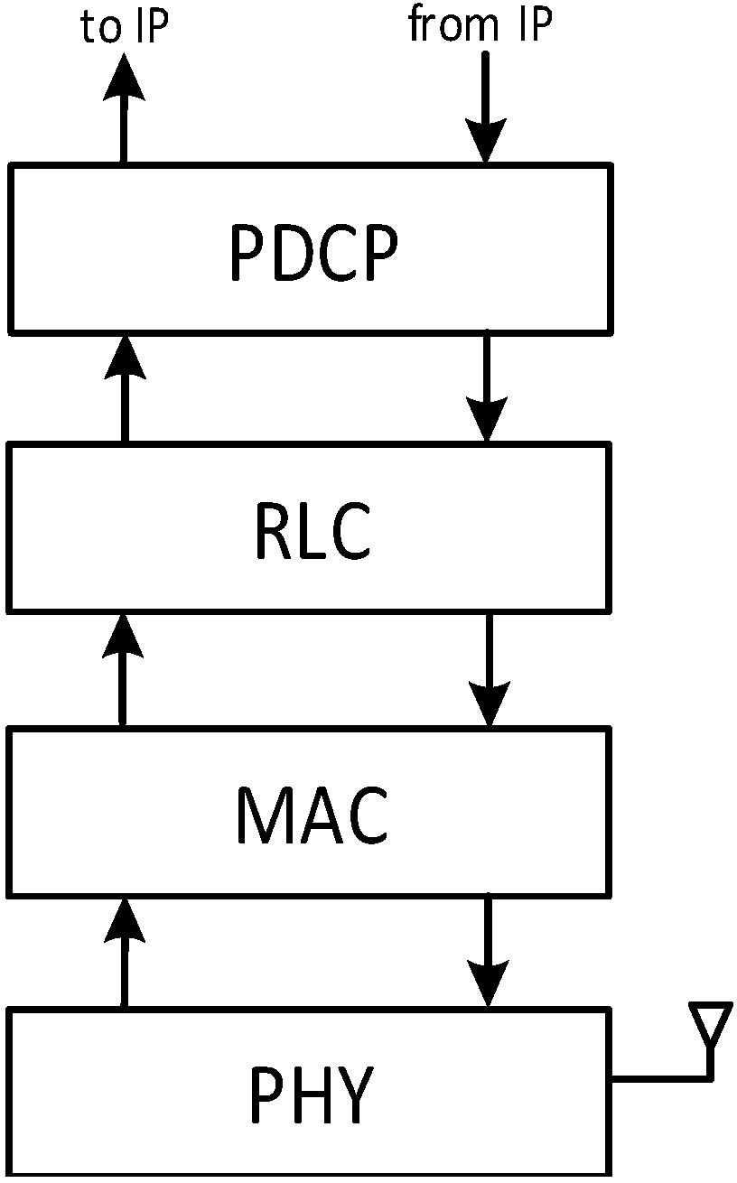
The LTE-A protocol stack incorporates a suite of four protocols, shown in Figure 1, which collectively make up layer 2 (i.e., the Data-link layer) of the OSI (Open System Interconnection) stack. The stack is present on both the eNB and the UE. Traversing the LTE-A stack from the top down, and assuming the viewpoint of the eNB, we first find the Packet Data Convergence Protocol (PDCP), which receives IP (Internet Protocol) datagrams, performs cyphering and numbering, and sends them to the Radio Link Control (RLC) layer. RLC Service Data Units (SDUs) are stored in the RLC buffer, and they are fetched by the underlying MAC (Media Access Control) layer when the latter needs to compose a subframe transmission. The RLC may be configured to work in three different modes: transparent (TM), unacknowledged (UM) or acknowledged (AM). The TM mode does not perform any operation. The UM, instead, segments and concatenates RLC SDUs to match the size requested by the MAC layer, on the transmission side. On the reception side, RLC-UM reassembles SDUs, it detects duplicates and performs reordering. The AM adds an ARQ (Automatic Repeat Request) retransmission mechanism on top of UM functionalities. The MAC assembles the RLC Protocol Data Units (PDUs) into Transmission Blocks (TB), adds a MAC header, and sends everything through the physical (PHY) layer for transmission.
In LTE-A resources are scheduled by the eNB’s MAC layer, at periods of a Transmission Time Interval (TTI) (1 ms). On each TTI, a vector of Resource Blocks (RBs) is allocated to backlogged UEs according to the desired scheduling policy. A TB may occupy a different number of RBs, depending on the Modulation and Coding Scheme (MCS) chosen by the eNB. The latter is selected based on the CQI reported by the UE, which is computed by the UE using proprietary algorithms, and corresponds to the Signal to Interference to Noise Ratio (SINR) perceived by the latter, over a scale of 0 (i.e., very poor) to 15 (i.e., optimal). Each CQI corresponds to a particular MCS, which in turn determines the number of bits that one RB can carry. Hereafter, we will often use the term CQI to refer to the (one and only) MCS that is determined by the former, trading a little accuracy for conciseness.
In the downlink (DL), the eNB transmits the TB to the destination UE on the allocated RBs. In the uplink (UL), the eNB issues transmission grants to UEs, specifying which RBs and which MCS each UE can use. In the UL, UEs need means to signal to the eNB that they have backlog. This is done both in band, by transmitting a Buffer Status Report (BSR) when scheduled, or out band, by starting a Random ACcess (RAC) procedure, to which the eNB reacts by issuing transmission grants in a future TTI. RAC requests from different UEs may collide at the eNB. To mitigate these collisions, the UEs select at random one in 64 preambles, and only RAC requests with the same preamble collide. After a RAC request, a UE sets a timer: If the timer expires without the eNB having sent a grant, that UE waits for a backoff period and re-iterates the requests.
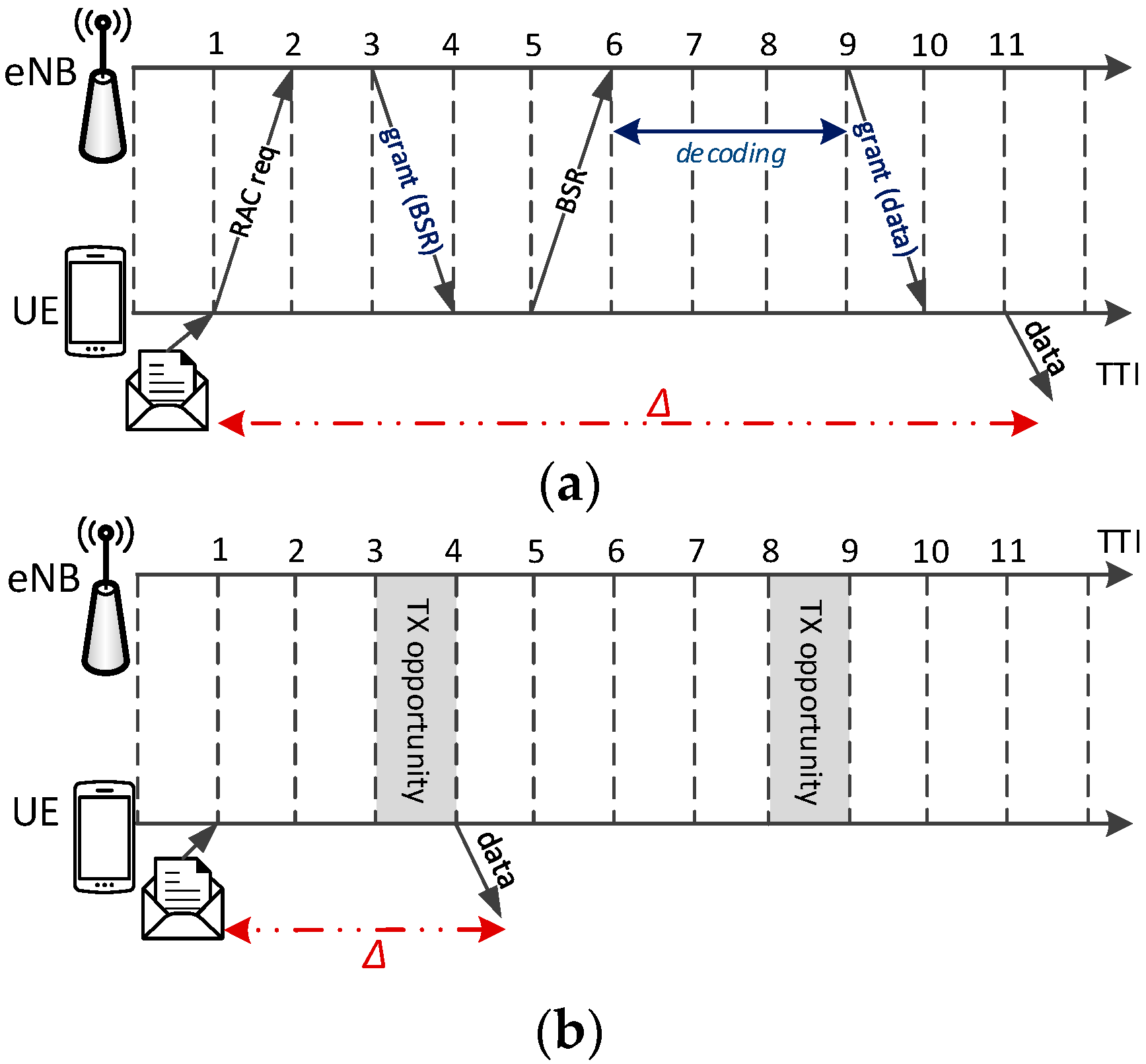
The 3rd Generation Partnership Project (3GPP) has standardized Network-controlled D2D communications for LTE-A in release 12 [11]. These are point-to-multipoint (or one-to-many) communications having proximate UEs as the endpoints, i.e., without the need to use a two-hop path having the eNB as a relay. A D2D link is also called sidelink (SL). The SL is often allocated in the UL spectrum in a Frequency Division Duplex (FDD) system, since the latter can be expected to be less loaded than the DL one, due to the well-known traffic asymmetry [9]. Under this hypothesis, D2D-enabled UEs must be equipped with a Single-Carrier Frequency Division Multiple Access (SC-FDMA) receiver [18]. The phrase network-controlled hints at the fact that the eNB is still in control of resource allocation on the SL, i.e., it decides which UE can use which resources. Two schemes have been envisaged to do this: a Scheduled Resource Allocation (SRA), and an Autonomous Resource Selection (ARS). SRA is an on-demand scheme, similar to resource allocation in the UL for standard communications: the UE must send a RAC request to the eNB, which grants enough space for it to send its BSR. Then, the eNB schedules SL resources accordingly and issues the grant to the UE for D2D communications, as shown in Figure 2a. On the other hand, in ARS the eNB configures a static resource pool, e.g., RBs every TTIs, and UEs can draw from it without any signaling. With reference to Figure 2b, the UE has new data to transmit at , but it needs to wait for the next eligible TTI, i.e., at . If more than one UE selects the same resources, then collisions will ensue. Note that P2MP D2D transmissions are not acknowledged, hence the sender cannot know which neighboring UEs received a message, and H-ARQ (Hybrid Automatic Repeat reQuest) is disabled. This is because (N)ACKs should be sent on a dedicated control channel to the sender, but dimensioning the latter would be impossible: in fact, with P2MP D2D transmission, there is no way to know in advance how many and which UEs will actually receive the message, or were meant to in the first place. P2MP D2D transmissions use UM RLC.
3. Related Work
Multihop D2D communications in LTE-A networks have been studied in several works, e.g., [12,13,14,15,16,17]. In [12], authors consider multihop D2D communications in order to extend the network coverage and propose a resource allocation strategy to optimize the throughput along the multihop paths. The study is restricted to two-hop communications where one UE is identified as relay node for one pair of transmitting and receiving UE, where each hop is a unicast point-to-point (P2P) D2D transmission. The work in [13] proposes a theoretical formulation for computing the outage probability of multihop communications. Also in this case, P2P D2D transmissions are considered. An opportunistic multihop networking scheme for Machine-type Communications is presented in [14]. UEs exploits the Routing for Low-power and Lossy Networks (RPL) algorithm used in Wireless Sensor Networks (WSNs) to compute the best route toward a given destination. In [15], game theory is applied to find the best multihop path for uploading content from one UE to the eNB. Both [14,15] differ from our work as they deal with the problem of delivering messages toward a given destination, instead of disseminating them to all the UEs within a given target area. Moreover, P2MP communications are not considered. In [16], P2P D2D communications are considered in order to enhance the evolved Multimedia Broadcast and Multicast Services (eMBMS) provided by LTE-A networks. In this case, the eNB transmits its multimedia content to a subset of UEs and the latter exploit D2D links to forward the data to UEs with poor channel conditions in the downlink, i.e., cell-edge UEs. A similar problem is tackled in [17], where UEs receiving data from the eNB use one P2MP D2D transmissions to distribute the data to neighboring UEs. The above paper focuses on finding the best subset of relay UEs so that the total power consumption is minimized and the rate requirements for all the UEs are satisfied. None of the above works address the problem of disseminating UE-generated contents toward all UEs within a geographical neighborhood.
Centralized resource scheduling is sometimes assumed in Wireless Mesh Networks (WMNs), although far less often than distributed resource scheduling, (see, e.g., [19,20]). In this context, our broadcasting problem is superficially similar to the one of channel assignment and/or link scheduling in WMNs. However, the assumptions are quite different from those made in LTE-A, since nodes in a WMN are usually equipped with few radios, which can be tuned to a larger number of channels. In LTE-A, all UEs have as many “radios” and “channels” as the number of RBs, which is in the order of several tens. More importantly, RBs can be allocated dynamically to UEs, whereas the algorithms presented in the literature often assume periodic transmissions and long-term, semi-static resource allocations. Moreover, unicast P2P transmissions are considered. For these reasons, the broadcasting problem considered in this paper cannot be accommodated using the above algorithms.
Broadcast diffusion problems have been addressed in the context of mobile ad-hoc networks (MANETs) (e.g., [21,22]), especially to support the dissemination of routing alerts or for gossiping applications [23]. Unlike LTE-A, where resources are centrally scheduled by the eNB on demand, the above networks are infrastructureless and have distributed resource allocation. Work [24] reviews and classifies the broadcasting methods in MANETs, focusing on how they try to limit collisions, the latter being the key issue in an infrastructureless network. For example, [25] employs similar hypotheses as this work (no knowledge of the underlying topology, fixed transmission range), although in a different technology, and proposes a method for limiting the number of broadcast relaying, and thus of collisions, by preventing nodes transmission based on an adaptive function of the number of received copies of the same message and the number of its neighbors. The considered function can then be tuned to trade user reachability with broadcast latency. We show in Section 5 that the latency of MDB is in line with the ones of [25], but the delivery ratios are higher, in similar scenarios. One of the main purposes of this paper is in fact to show that MDB can leverage LTE’s centralized scheduling. The combination of centralized scheduling and distributed transmissions is in fact unique to D2D-enabled LTE-A. Note that the ASR mode, described in Section 2, does instead allow unscheduled, collision-prone medium access, similar to what a MANET would do. In Section 5, we will show that such collisions actually hamper the performance.
4. Multihop D2D Broadcasting
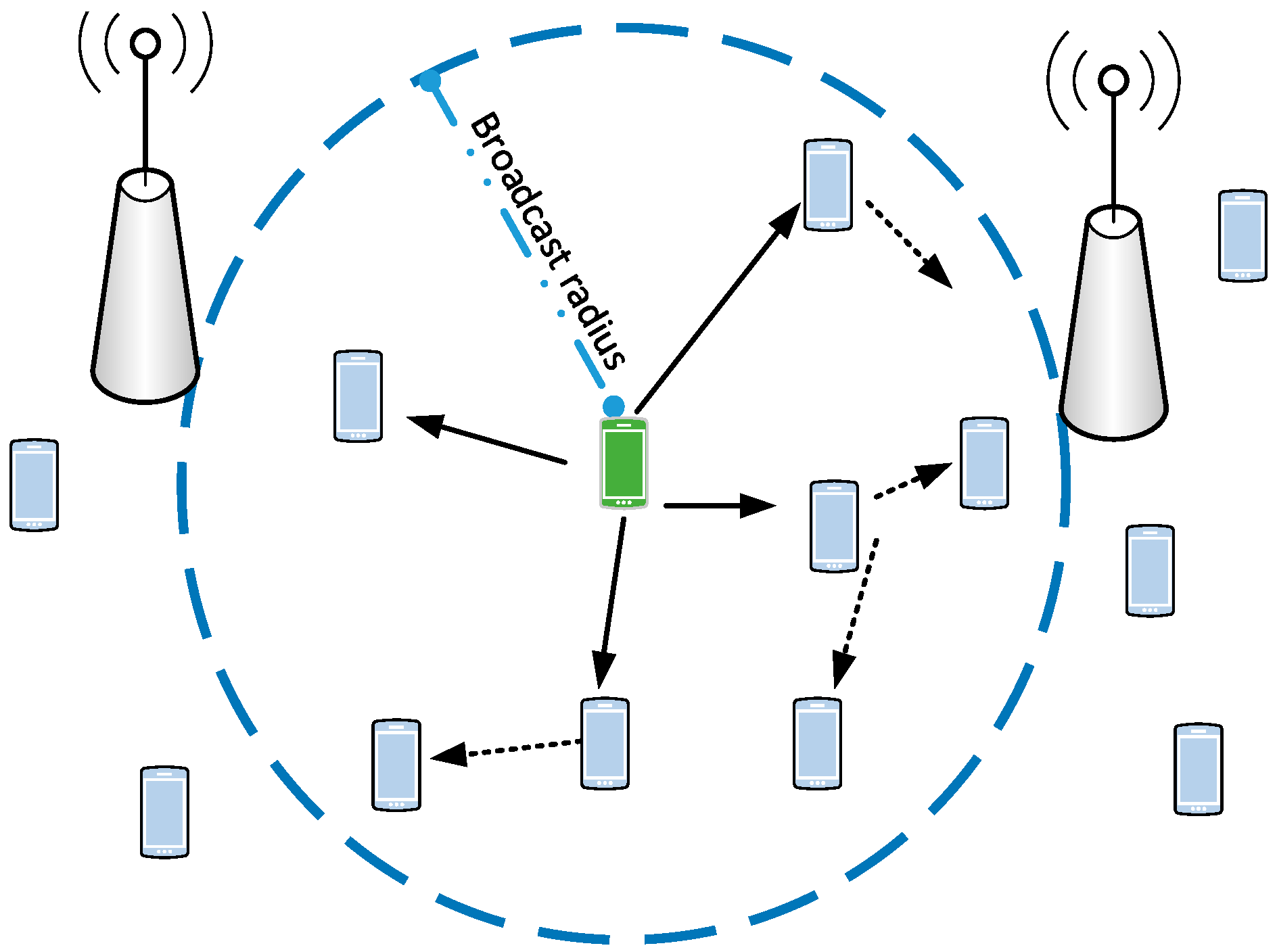
In the following, we consider an LTE-A system composed of several cells, where UEs are D2D-enabled. UEs run applications that may generate messages (e.g., vehicular collision alerts) destined to all other UEs running the same application, within an arbitrary target area. Our problem is to reach as many interested UEs in the target area as possible, using only P2MP D2D transmissions, relayed by UEs themselves, using as few resources as possible. The system model is shown in Figure 3, where the shaded UE originates a message that has to be delivered to all the UEs within the circle. The solid arrows represent the first P2MP D2D transmission, and the dashed ones represent transmissions relayed by UEs in the first-hop neighborhood of the originating UE. A UE that perceives collisions in the same time/frequency resources will still attempt to decode the message received with the strongest power, i.e., it will exploit the so-called capture effect, typical of wireless networks [26].
In multihop D2D broadcast, the eNB does not participate in data plane transmissions, i.e., it does not send data packets. Data-plane transmissions are instead performed by the UEs themselves, on behalf of the applications running on them. However, the eNB still controls the resource allocation, hence can affect the performance of the broadcast. We only assume that the eNB allocates resources for generic D2D transmissions using standard-compliant means (to be discussed later in this section), unaware of the fact that multihop relaying is going on for D2D transmissions, or of specific application requirements (e.g., deadlines, target areas, etc.). In other words, we assume minimal, standard-compliant support from the infrastructure.
Multihop D2D broadcasting requires that applications decide which UEs to target and how to relay messages, whereas the LTE-A network allocates resources for D2D transmissions to allow multihop relaying. This implicitly assumes a trusted environment, where UEs behave cooperatively. Security is notoriously difficult to enforce in broadcast networks, and we refer the interested reader to [27] for a discussion of security issues in D2D communications in particular. Regarding cooperation, UEs may be inclined to behave selfishly to save battery or to avoid increasing traffic volumes in pay-per-use plans. On one hand, suitable incentives and reputation-based schemes, such as those discussed in [28,29], could mitigate the problem. On the other hand, MDB services are supposed to be used also by embedded applications (e.g., application software running on cars), which have access to an energy source (e.g., the vehicle’s battery) and are not under the control of the end user (i.e., the car owner or pilot). In this last case, manufacturers would clearly benefit from coding cooperative behaviors in their embedded software. Hereafter, we assume that the UEs running MDB behave cooperatively. In Section 5 we evaluate the impact of selfish users on the performance.
Hereafter, we first discuss how UE applications should be designed in order to support broadcasting effectively, and then move on to discussing resource allocation policies in the network.
4.1. Broadcast Management within the UE
The two problems that UE applications should solve are: (i) how to identify the set of potential recipients; and (ii) when to relay D2D communications. The first problem boils down to identifying all the UEs running the same application in a certain geographical area. UEs running the same application can register to a reserved multicast IP address. This is relatively easy to do with IPv6 (Internet Protocol Version 6), where multicast address format is flexible. As far as defining the target area is concerned, we argue that the area depends on both the network scenario and the application: in a vehicular use case, for instance, vehicle collision alerts should reach vehicles in a radius of few hundred meters, whereas traffic notifications should probably travel larger distances, allowing drivers to route around congested areas. This means that the application message should contain enough information to allow a recipient UE to understand whether or not it should relay it. The information regarding the target area should then be embedded in the application-level message. A simple, but coarse, approach to do this is via a Time-to-live (TTL) field: the source UE sets the TTL in the application message to a desired maximum number of hops. Each relaying UE, then, decreases that field by one, and relays the message only if TTL > 0. While this is relatively simple and economical in space (an 8-bit field should be enough for must purposes), the downside is that the source UE can exert little control over the area covered by the broadcast, since the latter ends up depending on both radio parameters (such as the UEs’ CQI and their transmission power) and network topology (i.e., the position and density of UEs). The latter, in turn, is unpredictable and changes over time, so that any default value runs the risk of being too small or too high. The alternative is to code the target area within the message, by inserting the originating UE’s coordinates and the boundaries of the target area. Geographic coordinates can be taken from GPS positioning, or from geolocation services co-located with the network (e.g., using MEC solutions [8]). Geographic coordinates can be represented by two 32-bit floating points, indicating latitude and longitude with enough precision. A simple way to constrain the target area is to encode a maximum target radius, thus making it circular. Assuming that the target radius is represented in meters, a 16-bit integer should be large enough for most purposes. Encoding originator’s coordinates and target radius allows one to define with more precision the target area, which becomes independent of the UE’s density and location. This comes at the cost of using more space in the message (10 bytes overall instead of one). Increasing the message size, in turn, entails consuming more network resources for transmission. Obviously, more advanced definitions of target areas can also be envisaged, at the cost of further increasing the message payload. With a geographical representation of the broadcast domain, receiving UEs can then check whether their own position falls within the target area before relaying the message. This can be done by using simple floating-point arithmetic, i.e., by computing the distance from the originator and checking whether it is smaller than the target radius included in the message. Given the coordinates of the two points A and B (specified in latitude and longitude ), the Haversine formula [30] is used to compute the shortest distance over the earth’s surface, which is:
where is the earth’s radius.
Note that using a geographical representation (even one with infinite precision) still leaves a margins of uncertainty as to which UEs will receive the message: in fact any UE which is inside the target radius will relay the message, hence all UEs within an annulus of one D2D transmission radius outside the edge of the target area may still receive it.
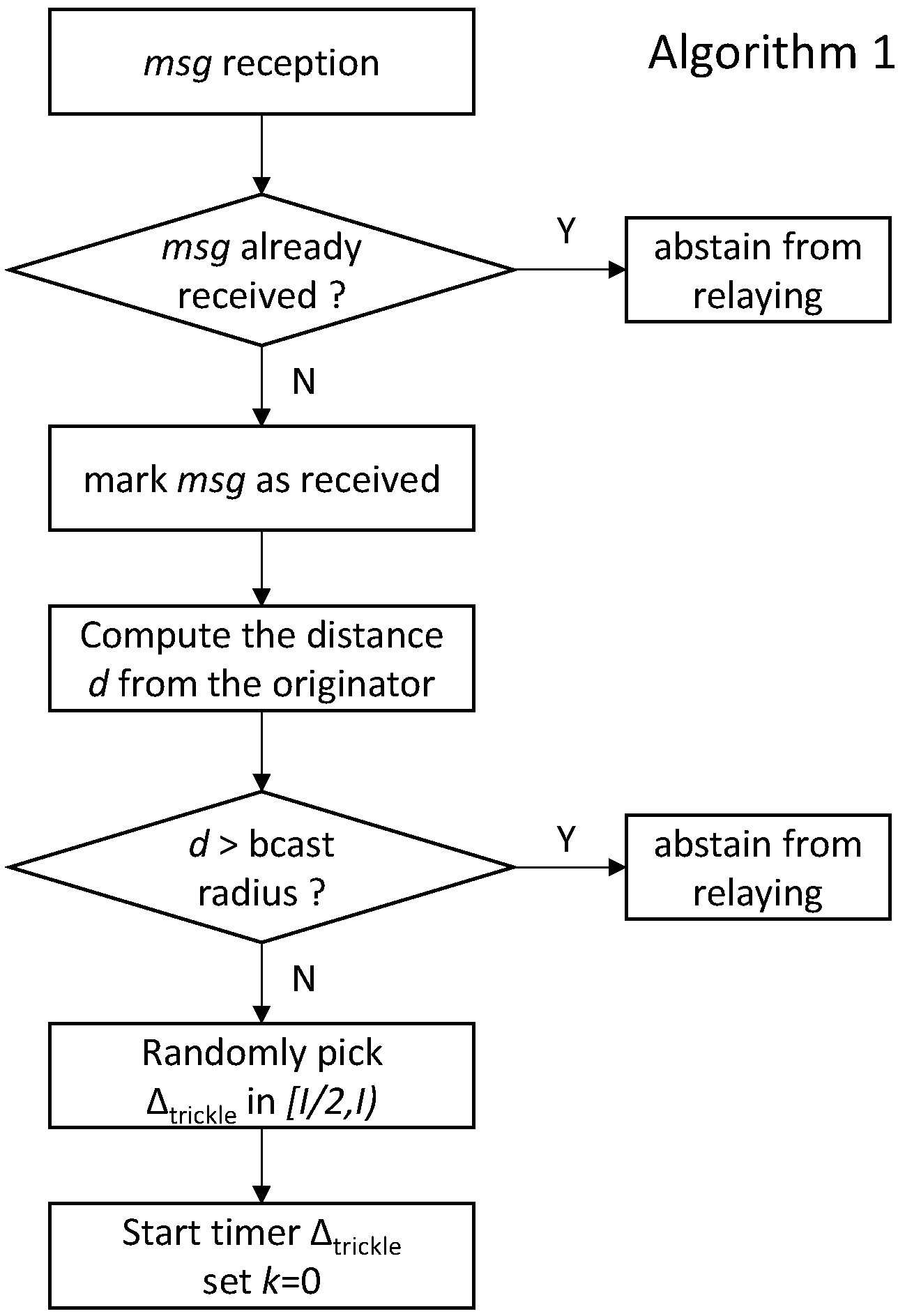
UE applications should also take care of relaying. In fact, it is at the application level that suitable algorithms can be run to make relaying efficient. A brute-force relaying, whereby UEs relay all received messages, would in fact quickly congest the network, since the same UE would receive the message from several neighbors, and relay them all unnecessarily. This would waste resources that could otherwise be used for other purposes. In order to make relaying efficient, a suppression mechanism can be used, e.g., the one of the Trickle algorithm [31]. Trickle is used in WSNs to regulate the relaying of updates and/or routing information. In that context, Trickle runs on each node participating in the broadcasting: before sending a message, the node listens to the shared medium in order to figure out if that information is redundant, i.e., enough neighboring nodes are already sharing it. If so, it abstains from transmission so as to avoid network flooding. In Trickle, two parameters can be configured: the Trickle Interval I and a number of duplicates . A UE selects a random time window in , and counts the copies of the same message received therein. The UE only relays a message if it receives fewer than copies of it. To sum up, Figure 4 depicts the flowchart of the operations performed by a UE application on reception of a message, when the Trickle suppression algorithm is employed. First, the UE checks whether the incoming message had already been received. If so, it abstains from relaying and the procedure terminates. Otherwise, it computes the distance from the originating UE and compares it with the maximum target radius. If the UE is inside the target area, then Trickle operations are initiated: the Trickle timer is started and the duplicate counter k is set to 0. Figure 5 shows that k increases on each duplicate reception within . When the above timer expires, the UE relays the message if .
Note that, in the absence of Trickle, UEs must be made to wait for a random time chosen uniformly in before attempting a relay. Parameter can be tuned to trade collision probability for latency. In fact, P2MP D2D transmissions will reach several UEs simultaneously. In the absence of random delays, these UEs will attempt relaying at the same time, since LTE-A is slotted. This may lead to collisions, regardless of how the eNB allocates resources (an issue which is dealt with in the next subsection).
So far we have assumed that a message is originated by one UE. However, messages are supposed to be generated as reactions to events (e.g., a vehicular collision), and the same event may be detected by multiple UEs, which might then initiate a broadcast quasi-simultaneously. In fact, whichever the allocation scheme in the network, there is a time window where all UEs that want to start a broadcast will be unaware of others doing so, even if they are within D2D hearing range of one another. That time window is around 10 ms with SRA (i.e., the time it takes to complete a resource allocation handshake), and equal to the period with ARS. What happens in this case depends on how the application handles the different broadcasts. A baseline solution is to do nothing. In that case, since the information included in the messages is not the same, since e.g., originators’ coordinates are different, the latter will be considered as different broadcasts by the Trickle instances running in the UEs’ applications, and will be broadcast independently. As a result, multiple, independent broadcasts related to the same event will traverse the network, with a corresponding increase of the traffic load. On the other hand, the applications running at the UEs can easily be endowed with the necessary intelligence to associate two (or more) messages, possibly with a different payload, to the same event: for example, if the distance between the originators’ is below a threshold, the message type is the same, and the reception times are again within a predefined window (which may be computed based on the Trickle window). In this case, merging can occur, i.e., the various broadcasts messages are associated to the same Trickle instance, thus being perceived as duplicates of the same broadcast process. Note that MDB can also accommodate messages generated by entities other than UEs, e.g., nodes located in the Internet, the LTE core network, or—possibly—Mobile-edge Computing servers running applications on behalf of the UEs. In that case, the network can select one (or more) proxy originator UE(s) and send them the message from the serving eNB(s) using downlink transmissions. The receiving UE(s) can, in turn, initiate the broadcasting procedure as described above.
4.2. Resource Allocation in the Network
As discussed in Section 2, the eNB controls resource allocation, and may use either SRA or ARS. We now compare the two approaches, highlighting their pros and cons in the context of multihop relaying, also taking into account that multicell relaying may be required.
As far as latency is concerned, using SRA requires each UE to undergo one RAC handshake per transmission. As shown in Figure 2a, this handshake takes a 10 ms delay in the best of cases, i.e., when the eNB issues grants immediately. If RAC collisions are experienced, or the eNB delays scheduling because the UL is congested, the per-hop delay may be even larger. On the other hand, with ASR, a UE can send a message as soon as a transmission opportunity becomes available, without the need of going through a RAC/BSR handshake. Thus, with ARS the maximum scheduling delay is given by the resource allocation period . Using ASR, especially with small periods, allows faster access to the medium. However, this entails allocating a large share of resources to P2MP D2D transmissions statically, thus wasting resources when these are not required, and preventing standard UL communications to use them. Therefore, with ASR, latency is traded off for resource efficiency.
The two allocation schemes differ greatly regarding collisions. When using SRA, the only possible collisions are those of simultaneous RAC requests at the eNB. However, these are quite unlikely. The LTE-A standard requires UEs to select a preamble among 64 possible choices. Simultaneous RAC requests with different preambles do not collide. Furthermore, when a RAC request is not answered by the eNB (either because of a RAC collision or because the eNB does not have resources to spare), the UE simply sends it again after a backoff time. Thus, RAC collisions do delay the broadcast process, but they also desynchronize relaying UEs, which is a positive side effect. With SRA, data transmission on the SL is instead interference-free, since the eNB generally grants SL resources to one transmitting UE at a time. The only exception to that rule is when the eNB exploits a frequency reuse scheme (such as the one in [32]), in which case faraway, non-interfering UEs may be granted the same RBs simultaneously. However, this happens exactly because the eNB knows that they will not interfere with each other. If, instead, ARS allocation is used, UEs claim RBs on the SL for their own transmission without a central scheduling and without their neighbors knowing, hence the intended receivers face unpredictable interference. The latter can be mitigated by having the UEs select at random which RBs to use, and by dedicating more resources to SL transmissions, which decreases the efficiency. Moreover, ARS allocation is periodic, hence it implicitly forces synchronization among groups of UEs: all UEs whose application requests a relay in the same ARS period will end up accessing the SL at the next ARS opportunity, hence increasing the likelihood of collisions. This would happen at each hop. Furthermore, since a sender does not know if collisions have occurred, the only possible countermeasure to increase the reliability of a transmission would be to retransmit the same message more than once.
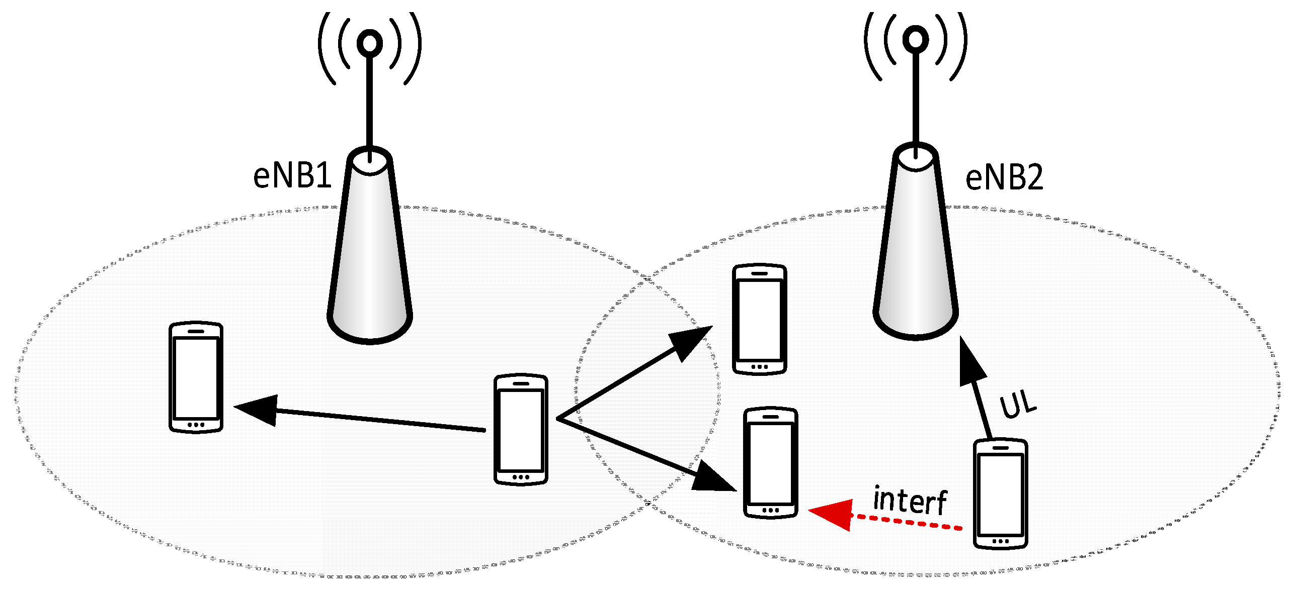
As already discussed, a target area may include more than one cell, as shown in Figure 6. This poses the problem of coordinated resource allocation among neighboring cells. In fact, if each cell allocates SL resources autonomously, cell-border UEs will be subject to interference from UL transmissions in the neighboring cells, hence they may be unable to receive P2MP D2D transmissions. This problem is likely to affect more heavily dense networks [33], where cells are smaller.
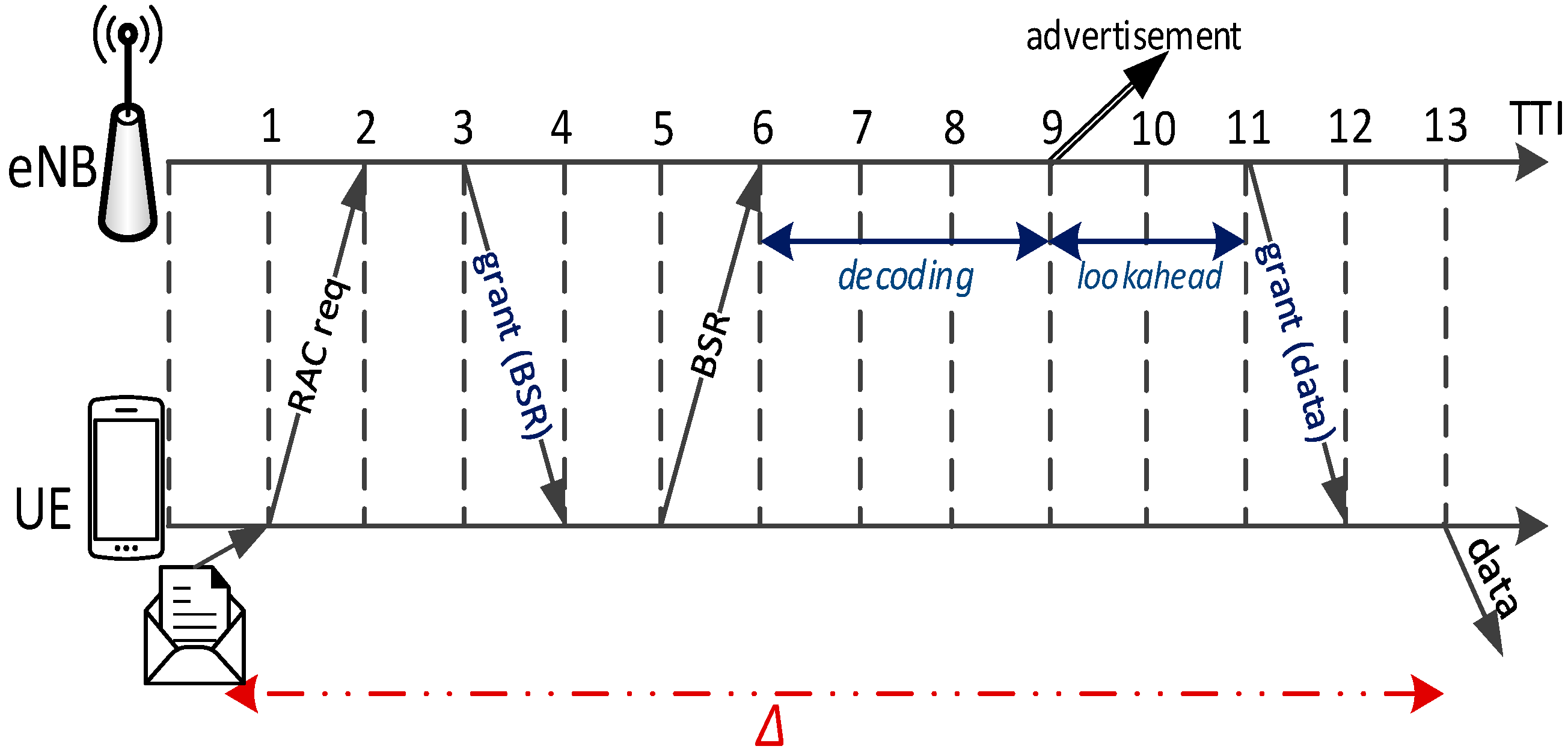
If the network uses ARS allocation, coordination is fairly easy to achieve: all it takes is that neighboring cells use the same allocation pattern. If, instead, SRA is used, resources are allocated on demand, hence the eNB must share information regarding their allocation using the X2 interface. For instance, an eNB may inform its neighbor(s) about which RBs will be allocated to a cell-border P2MP D2D transmission in a future TTI, so that the neighboring eNB(s) avoid allocating the same resources to UL or D2D transmissions in the vicinity of the cell border. This requires the sending eNB to plan scheduling on the SL (at least for cell-border UEs) with a lookahead of some TTIs, enough for the above message to reach its neighbor through the X2. With reference to Figure 7, at the eNB informs its neighbor that, in a future TTI, a grant for a cell-border P2MP D2D transmission will be scheduled on a given set of RBs. The receiving eNB marks the advertised RBs as occupied at the appointed TTI, and performs its usual scheduling. The lookahead mechanism can be expected to add a negligible delay to the broadcast diffusion, since the X2 connection is normally wired and low-delay.
The eNBs should also select the MCS of P2MP transmissions. Such choice should strike a tradeoff between two conflicting objectives, i.e., transmission range and resource consumption. In fact, selecting more performing MCSs implies reducing the number of RBs required for a transmission, since more bits will be packed in the same space. However, it will also decrease the transmission range, since the distance at which the SINR will be high enough to allow successful decoding decreases with the CQI. This implies that more hops will be required to cover a given target area. Conversely, selecting less performing MCSs will require fewer hops, but more RBs per transmission. Note that the eNB must choose the MCS only if it uses SRA allocation: in this case, in fact, the eNB sends D2D grants, which carry indication of the transmission format. If, instead, ARS is used, UEs may select the MCS autonomously, at least in principle. In practice, we argue that the eNB should still make that choice, and possibly advertise it periodically using RRC procedures. In fact, the eNB is in a better position than single UEs to assess the UE density or location, hence to select the most suitable cell-wide transmission format.
5. Performance Evaluation
In this section, we employ system-level simulations to assess the performance of MDB services. To do so, we use SimuLTE [34], a simulation framework based on OMNeT++ [35], which models both eNBs and UEs endowed with a Network Interface Card (NIC) that implements the data plane of the LTE-A protocol stack, from application- to physical-layer. In particular, it allows one to simulate both P2P and P2MP D2D communications [36]. For the scope of this paper, we enhanced the simulator with a new application module running at the UE side, which is able to send messages to neighboring UEs, leveraging P2MP D2D communications provided by the underlying LTE-A NIC. The receiving UE can in turn relay the message using again P2MP D2D communications. In the following, we consider a first scenario where UEs are static and we evaluate the impact of the different application- and MAC-level mechanisms described in Section 4. Then, we will investigate a vehicular network scenario, where UEs are mobile, as a use-case for MDB.
5.1. Tuning of the Multihop P2MP Settings
Our first simulation scenario, shown in Figure 8, includes five adjacent eNBs, located at a distance of 400 m from each other. We initially assume that each eNB serves 30 UEs with P2MP D2D capabilities, which are deployed randomly in a narrow strip along a straight line. UEs are assumed to be static. Their transmission power is 30 dBm in the UL and 15 dBm in the SL. The channel model includes Jakes fading and log-normal shadowing. Table 1 reports physical-layer parameters. We assume that broadcast messages transport a 4 byte payload, representing a code for indicating the type of the message. Considering the additional information for the originator’s coordinates and the target radius discussed in Section 4, we assume a total length of 14 bytes. A message is generated by a random UE every second, starting a new broadcast. As we will show later, the duration of each broadcast is less than one second, hence we can consider each message dissemination as an independent event. For each configuration, we run one instance of 100 s and statistics are obtained by averaging 100 independent broadcasts. Confidence intervals at the 95% level are shown. In the following, we assume that UEs relay the same message only once and that the target radius is 1000 m, unless otherwise specified.
5.1.1. Varying Application-Level Settings
In this subsection, we evaluate how different settings of the UE’s application layer affect the performance of the broadcasting and compare MDB with the relaying made by the eNB. We assume that the eNB uses the SRA allocation policy, using the scheduling algorithm described in [32], where two or more UEs can reuse the same RBs if they are not interfering each other. In particular, interference conditions are modeled through a conflict graph [38], which is maintained by the eNBs according to UEs’ location information. In the conflict graph, two UEs are conflicting if the power they receive from each other is above a threshold of −50 dBm. In that case, the UEs are placed on different RBs, otherwise they can share the same RBs.
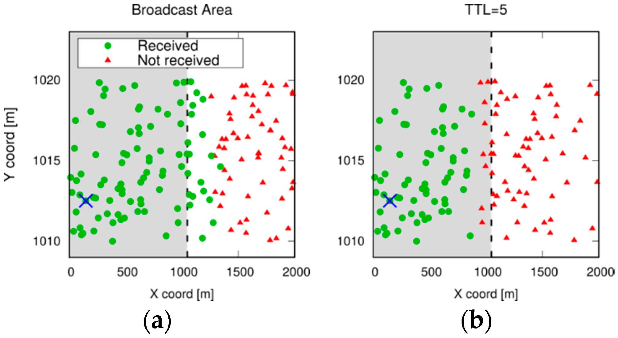
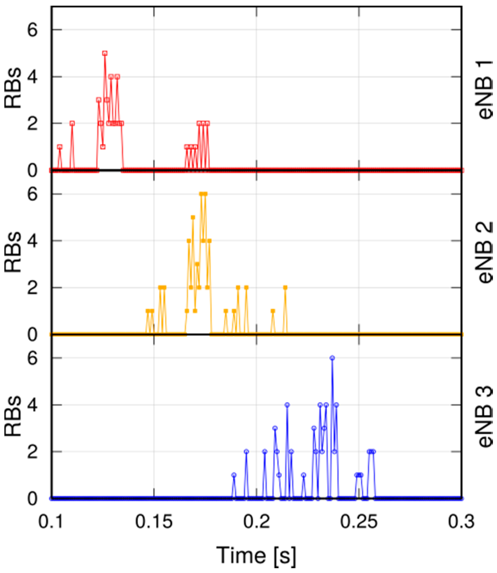
Figure 9 shows which UEs receive a broadcast message, when either TTL or GPS coordinates and radius are used. The UE marked with the cross is the one that originates the message, and the boundary of the target area (i.e., the shaded one) is marked by the vertical dashed line. Note that the line only looks straight because the scale on the y-axis is stretched. UEs that received the message are shown as green circles, whereas red triangles represent UEs that did not. Using coordinates and radius (top left of Figure 9) allows the message to reach all the desired UEs, and few of those outside the range. When TTL is used, the set of UEs depends on the initial TTL value. If the value is set to 5 or 6, some UEs at the border do not receive the message, whereas setting it to 7 covers the entire target area. However, if the line is moved in either direction, or the UE density or the network MCS change, that value stops being optimal and must be recomputed. In order to exemplify the dissemination process of the message, Figure 10 shows the per-TTI allocation of RBs at the eNBs involved in the broadcasting process, which is started by a UE served by eNB1. Thus, the latter allocates RBs to UEs under its control to let them relay the message. After some time, the message reaches UEs served by eNB2 and eNB3, which in turn start granting transmission resources to them. eNB4 and eNB5 do not allocate RBs, since their served UEs are outside the target area.
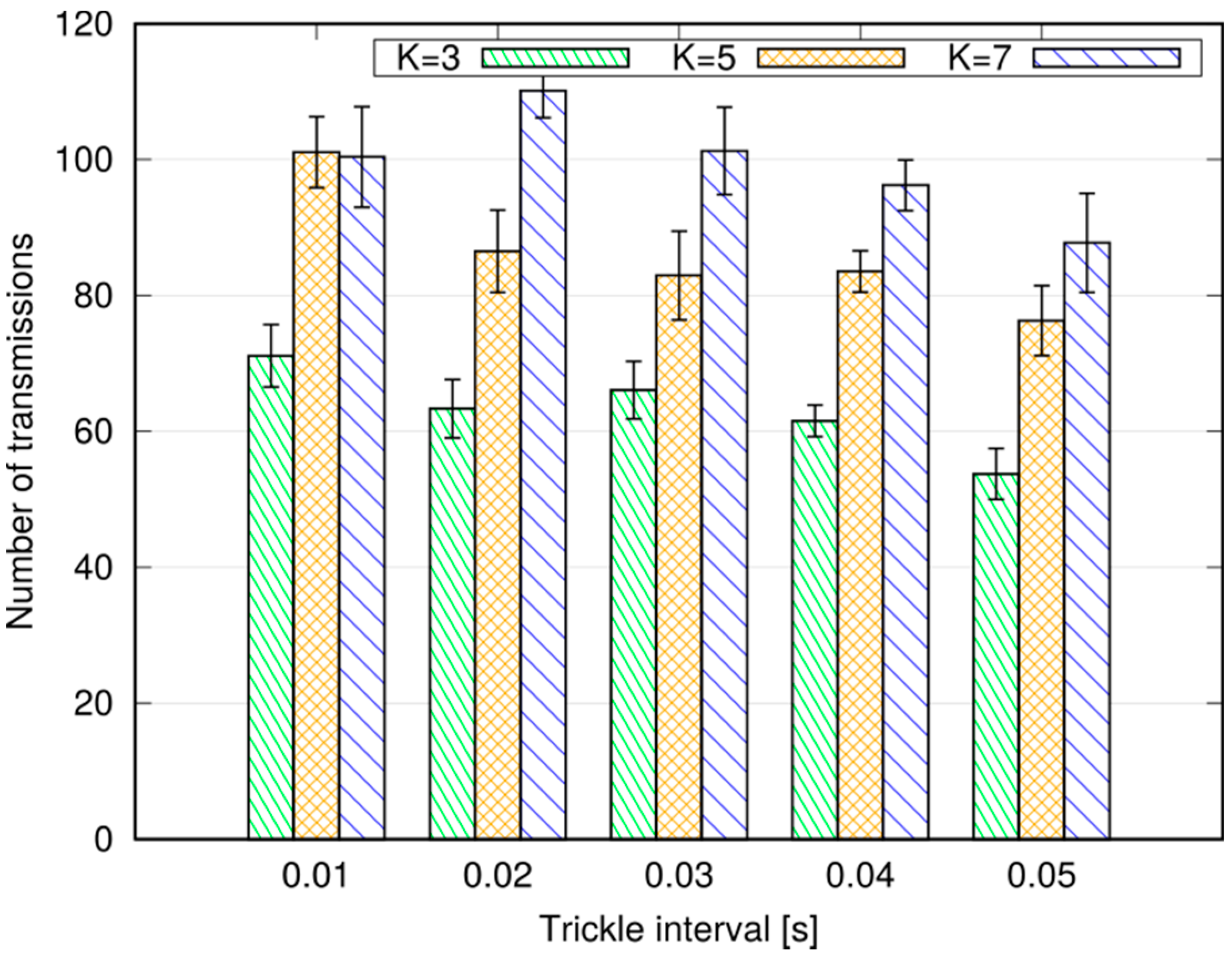
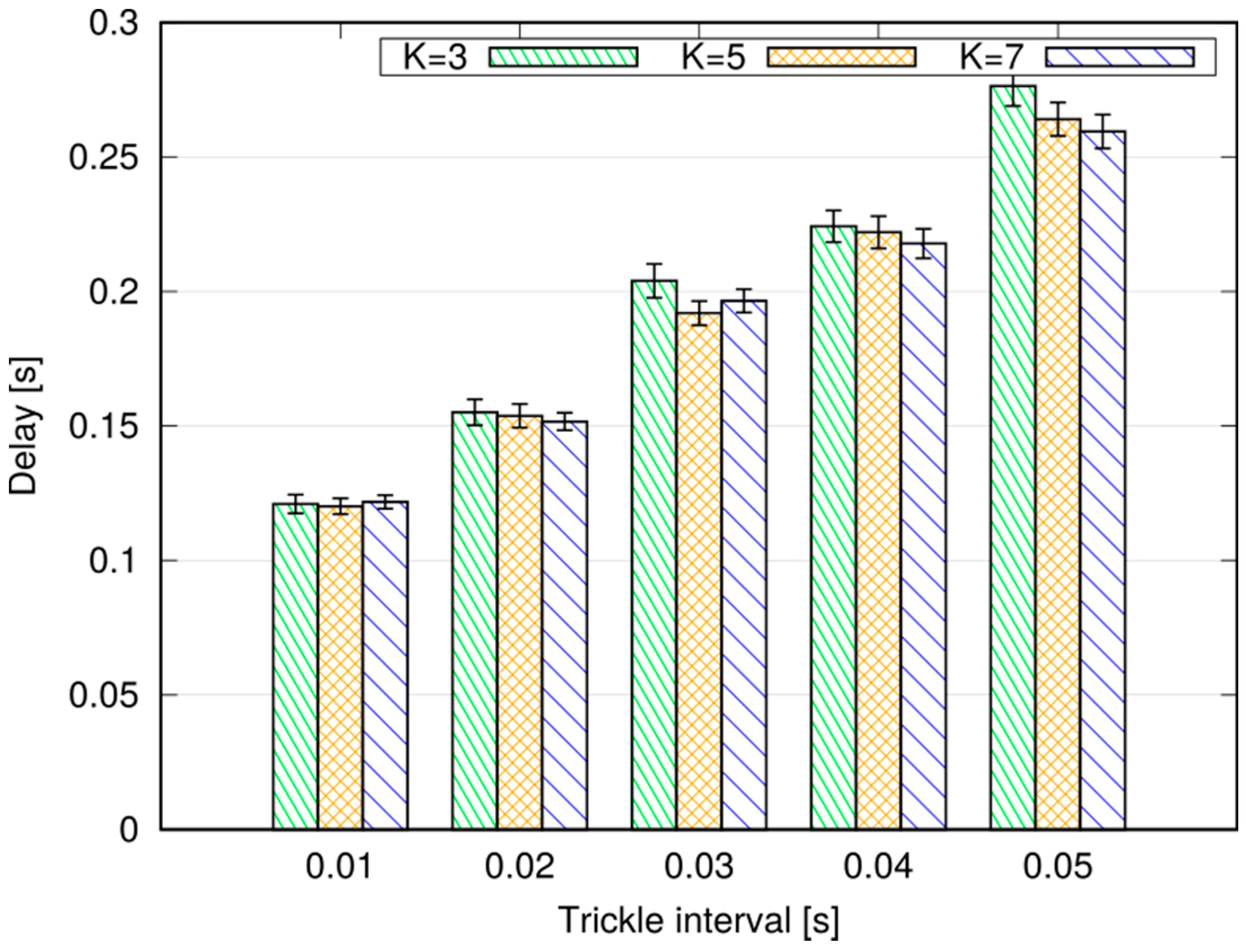
We now evaluate the impact of the Trickle suppression mechanism on MDB. In particular, we consider different settings for its relevant parameters and . We recall that a UE relays a message if fewer than duplicates are received within a time randomly selected in the range , being the Trickle interval. Defining S as the number of transmissions performed by all UEs in the floorplan to relay a single broadcast, Figure 11 shows , whereas Figure 12 reports the 95th percentile of the time required to complete the dissemination, computed as , where is the time at which the originating UEs starts the broadcast, and is the time at which none of the UEs that have received the message can forward it anymore (either because they already have, or because Trickle suppressed relaying).
We observe that the combination of large values of and small values of allows us to transmit fewer messages, hence saving in terms of radio resources and power at the UEs. Of course, larger Trickle intervals result in larger delays, since UEs wait longer before relaying a message. The value of has a negligible impact on the latency of the broadcasting. If our primary objective is to provide fast diffusion of a message, we should then select a short Trickle interval and a small value of the threshold .
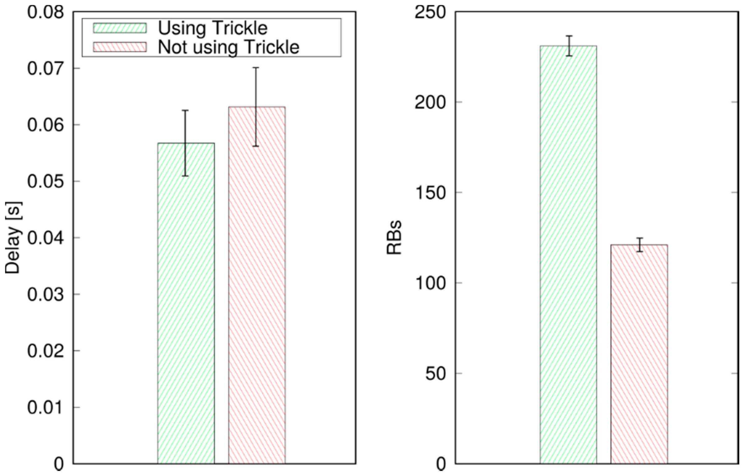
For the above reasons, we now set the Trickle parameters to and , and compare the performance of the with and without Trickle broadcasts. Figure 13, left, shows that adding Trickle increases the mean delay: in fact, Trickle adds delay before a relaying is attempted, and prevents some UEs from relaying the message at all. These delays add up at each hop. However, Trickle allows significant resource savings, quantifiable in about half the RBs.
We then evaluate the performance of MDB against unicast eNB relaying. As far as the latter is concerned, we assume that the source UE sends the message to the eNB, which relays it within its cell using unicast DL transmissions, and sends it to its neighboring eNB using the X2 interface. We envisage two options to geofence the broadcast: one (which is called eNB relaying) assumes that the eNBs relay the message to all UEs in their cell, hence the target area consists of a number of cells. The other solution (called enhanced eNB relaying) consists in selecting the subset of UEs to target in each cell based on their geographic position. In both cases, the eNBs must be endowed with an application layer that sends and receives messages. With eNB relaying, the eNB application in the originating cell must read the message payload, and—specifically—the GPS coordinates of the source UE and the target radius, to understand which other neighbors to contact, if any. The eNB applications in the other cells will just receive the message and request the unicast forwarding. With the enhanced eNB relaying, instead, all eNB applications must also read the GPS coordinates and radius, find out which UEs are within the target area, and request the unicast relaying. This entails knowing the position of the UEs in the cell. As already stated, this can be achieved leveraging MEC solutions, but it can be expected to have a cost, in terms of added communication latency and overhead.
Figure 14 reports the 95th percentile of the delay and the allocated RBs in the DL subframe. As expected, the broadcast is completed sooner using unicast relaying, since UEs can be reached in two radio hops plus, possibly, a (fast) X2 traversal. However, the cost in terms of allocated resources is non-negligible: a broadcasting occupies 230 RBs in the DL subframe, whereas MDB does not require the eNB to use the DL spectrum at all. Note that, in a 10 MHz deployment, using 50 RBs per TTI, unicast relaying would stall the DL for 4–5 consecutive TTIs, which is unadvisable.
5.1.2. Varying MAC-Level Settings at the eNB
In the following, we assume that the target area is embedded in the message, and Trickle suppression is enabled.
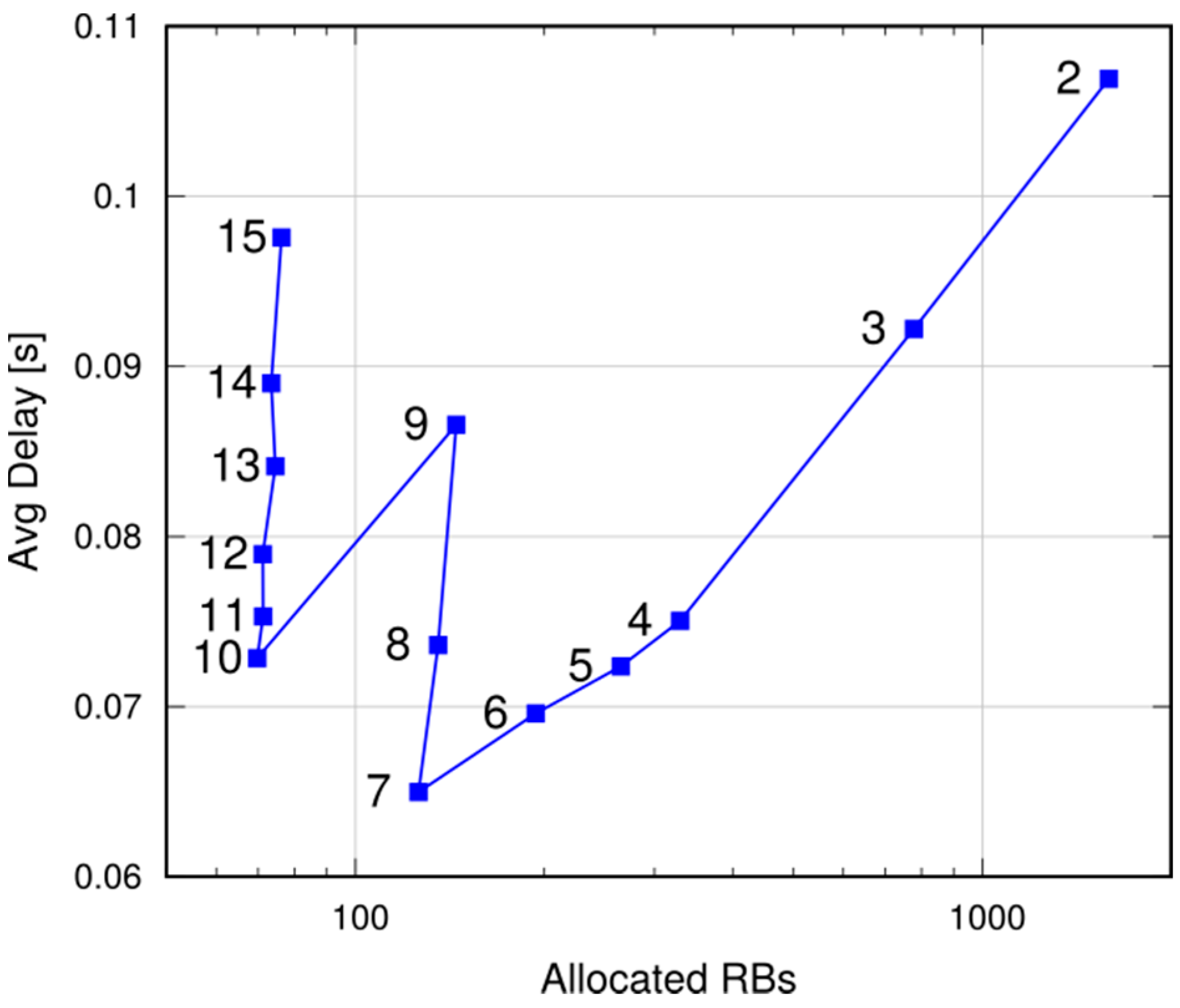
We first discuss the tradeoff involved in the choice of the MCS at the cell level. In Figure 15, the x axis reports the mean of the total number of RBs per broadcast, whereas the y axis shows the mean reception delay of UEs within the target radius. Resources are allocated via SRA, and the points represent the CQIs (which determine the MCS). As expected, the number of allocated RBs decrease with the CQI. In fact, higher CQIs correspond to more performing MCSs, hence to more bits per RB. A message transmission occupies 11 RBs with CQI 3, and one RB with CQI 15. However, using larger CQIs increases the number of hops, hence the latency. This is evident in the two segments 7–9 and 10–15, where the same number of RBs is used, but larger latencies are obtained, since the reception range is reduced. However, latency also increases with too small CQIs. As previously discussed in Section 3, the probability of correct reception decreases with the number of RBs employed, due to frequency-selective fading, all else being equal. The MCS corresponding to CQI 7 strikes a good tradeoff between latency and resource occupancy. While the absolute values in the graph are a function of the target radius, qualitatively similar results (although on different scales on both axes) are obtained when the radius is varied. From now on, CQI 7 is used in the simulations.
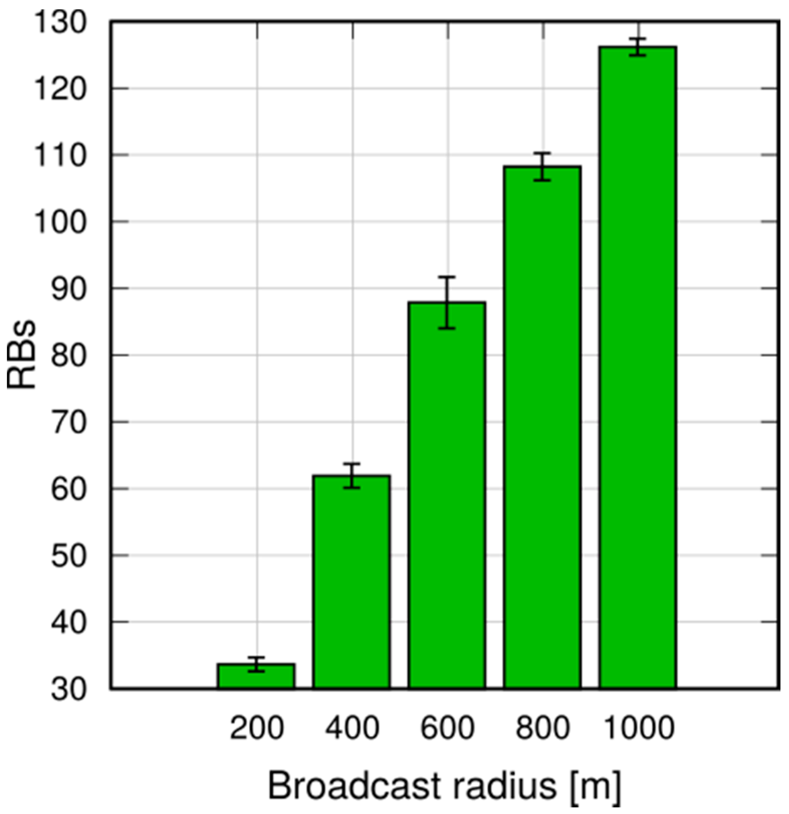
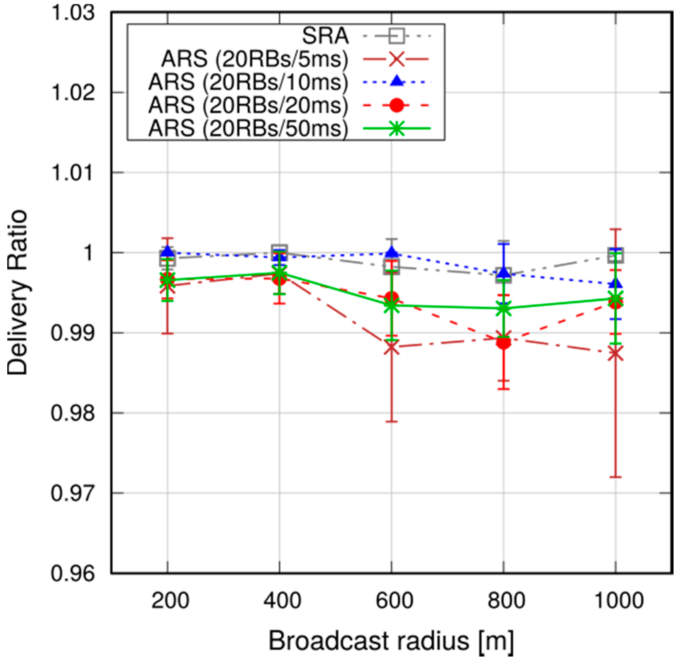
We now evaluate the two resource allocation strategies. Figure 16 and Figure 17 report the average and the 95th percentile of the delay, for different target radiuses, achieved with SRA and ARS. We configured ARS with four different patterns, consisting of 20 RBs allocated at periods of 5, 10, 20 and 50 ms respectively. When the period is small enough (i.e., 10 ms or below), ARS is faster than SRA, since the time to the next transmission opportunity is smaller than the duration of a RAC handshake. This comes at the price of higher resource consumption: ARS consumes many more resources, which go unused when there is no traffic. For instance, with a period of 5 ms, one eNB must reserve 8% of its resources for P2MP D2D broadcasts (still assuming a 10 MHz deployment). SRA, instead, only uses the RBs requested by the UEs, which are around 130 per broadcast over a 1000-m radius (involving 5 eNBs), also factoring in BSR transmissions, as shown in Figure 18. A back-of-the-envelope computation shows that, since UEs send one broadcast per second, then the resource occupancy of SRA is less than 130 RBs per second in the whole network, against 10 thousand for ARS at 5 ms.
Figure 19 reports the percentage of UEs that actually receive the message, which is close to 100% and fairly insensitive to the target radius. Note that the last result is partly due to the spatial reuse policy, which allows an eNB to schedule more than one D2D transmission on the same time/frequency resources.
To put the above results into context, we observe that the average broadcast latency with SRA and a radius of 800 m is around 50 ms (see Figure 16), and the corresponding delivery ratio is above 99% (Figure 19). Compared to [25], which addresses broadcasts in an 802.11-based MANET in a somewhat similar scenario (although similarities between such different technologies as 802.11 and LTE are to be taken with a pinch of salt), we note that the latencies are similar, but our delivery ratio is remarkably higher (99% against 90–98%), despite the fact that LTE relies on much smaller UE D2D transmission radiuses (100–150 m against 500 m in [25]).
From now on, we use SRA as the resource allocation scheme, since it achieves a good tradeoff between latency and resource consumption.
5.1.3. Varying the Network Scenario
We now show what happens when network conditions are modified. More specifically, we show what happens if quasi-simultaneous broadcasts are started at nearby UEs (which may register the same event, e.g., a collision, and start dissemination independently). Moreover, we discuss how the performance of MDB is affected by UE density in the network, and the impact of selfish users.
In order to assess the impact of multiple originators for an event, we perform simulations where two broadcasts are started simultaneously by two UEs located at a maximum distance of 20 m. Figure 20 shows that the 95th percentile of the delay is slightly smaller than in the case where the broadcast has a single originator. This is because two UEs transmit simultaneously at the first hop and their messages can be possibly received by a few more UEs than in the single-originator case. On the other hand, merging makes little difference as far as delay is concerned, once we assume two originators. The effects of merging two broadcasts into a single Trickle instance are instead visible in terms of allocated RBs, as shown in Figure 21. As expected, having two independent broadcasts doubles the number of allocated resources, whereas the RB occupation in the case of merged broadcasts is essentially the same as the case with a single originator.
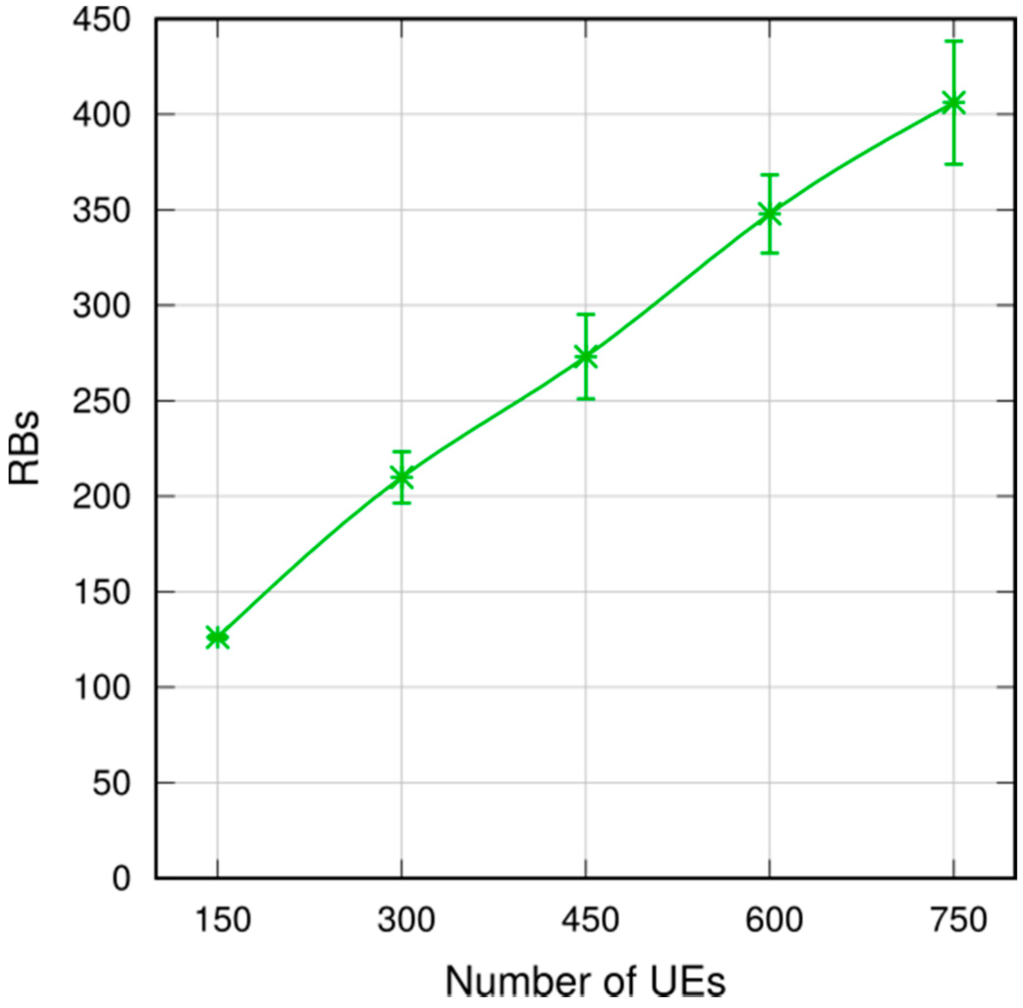
We now assess the performance of MDB in denser networks. We increase the number of UEs served by each eNB from 30 to 150, resulting in a total number of UEs of up to 750. Again, we use a target area with a 1000 m radius. Figure 22 shows the 95th percentile of the delay. We observe that the delay decreases with the UE density, and it is slightly above 80 ms with 750 UEs. This is explained by the larger number of UEs receiving a single broadcast message, hence a larger number of potential relays. This in turn increases the probability of reaching farther UEs. Clearly, more transmissions come at the cost of a higher resource consumption, as reported in Figure 23: the number of allocated RBs per broadcast increase from 130 RBs (with 150 UEs) to about 400 RBs with 750 UEs. Interestingly, the ratio between the allocated RBs and the number of UEs decreases. In fact, more transmissions means more duplicates too, hence more UEs abstain from transmission thanks to the Trickle suppression mechanism.
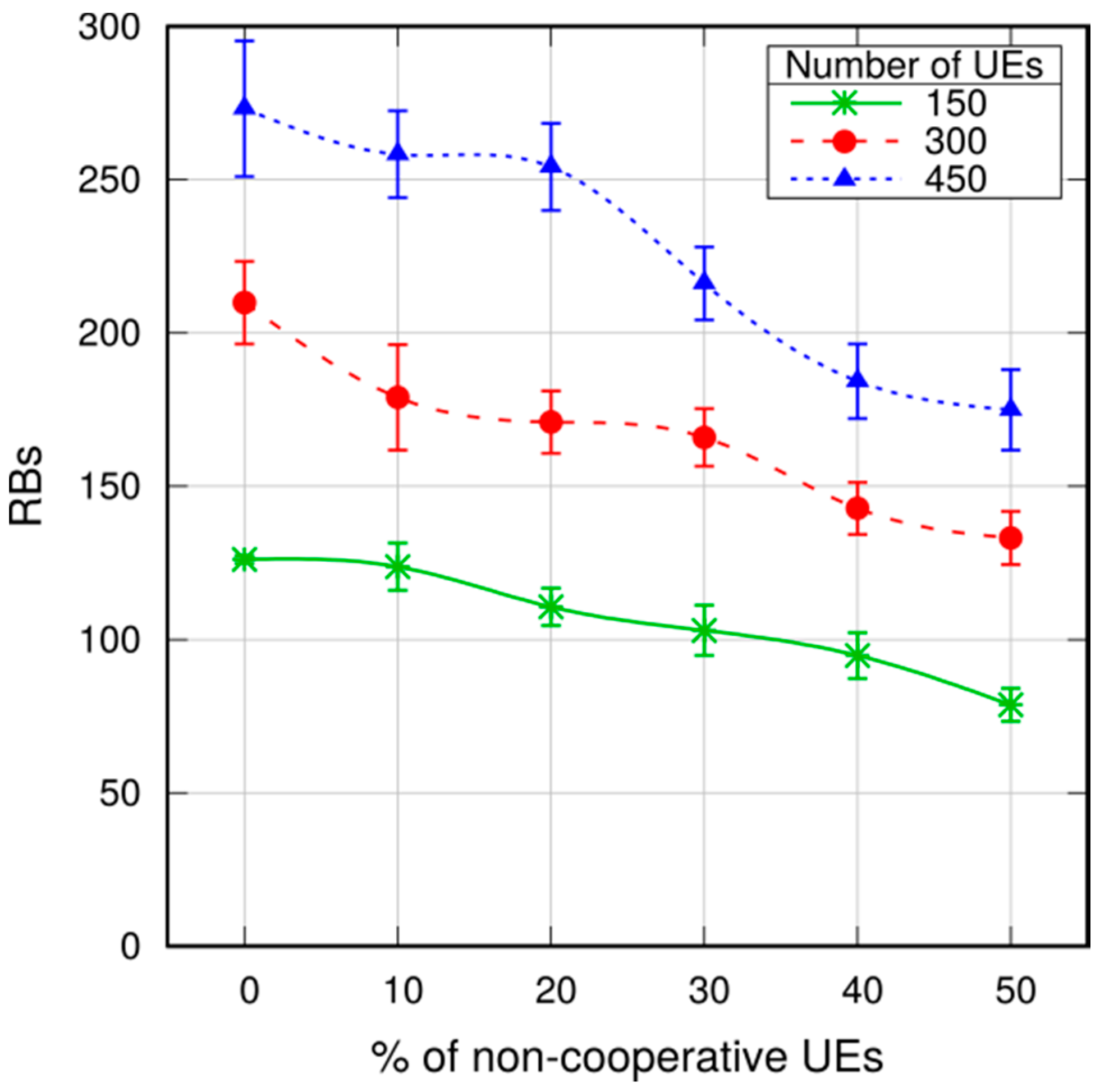
As discussed in Section 4, some selfish UEs may refuse to relay messages, e.g., to save their battery. In order to assess the impact of selfish users in MDB, we simulated scenarios with an increasing percentage of selfish UEs, at different densities. Figure 24 and Figure 25 show respectively the 95th percentile of the delay and the number of RBs allocated per broadcast. As expected, increasing the percentage of selfish UEs results in a larger, though tolerable, delay. This is due to the reduced number of transmissions, which in turn also reduce the number of allocated RBs. In any case, the reliable delivery of the message is ensured by the Trickle suppression mechanism: in fact, (cooperative) UEs relay the messages if they perceive that their doing so is necessary to its diffusion. It is worth noting that the results obtained with 300 UEs and 50% of non-cooperative UEs (rightmost end of the dotted line in Figure 24 and Figure 25) are similar to those obtained with 150 UEs and no selfish UEs (leftmost end of the continuous line in Figure 24 and Figure 25). All things considered, the presence of randomly placed selfish users can be accounted for as an equivalent reduction in user density as far as latency and RB utilization are concerned.
5.2. Multihop D2D Broadcasting in Urban Vehicular Networks
We now discuss how MDB performs in a vehicular network. In this scenario, moving vehicles should be able to exchange information (like alert messages or traffic updates) with other vehicles, roadside elements (e.g., traffic lights) and/or pedestrians in a fast and efficient way. The inherent proximity of the communications makes D2D transmissions (possibly exploiting multihop transmissions) one of the key enabling technologies for these services.
For this reason, we recently enhanced SimuLTE so as to make it interoperable with Veins [39,40], an OMNeT++-based framework for the simulation of vehicular networks, which is widely used by the research community. This way, it is possible to endow vehicles with an LTE NIC, immersing them into a cellular infrastructure where they can communicate with other network elements and/or among them, possibly exploiting D2D transmissions.
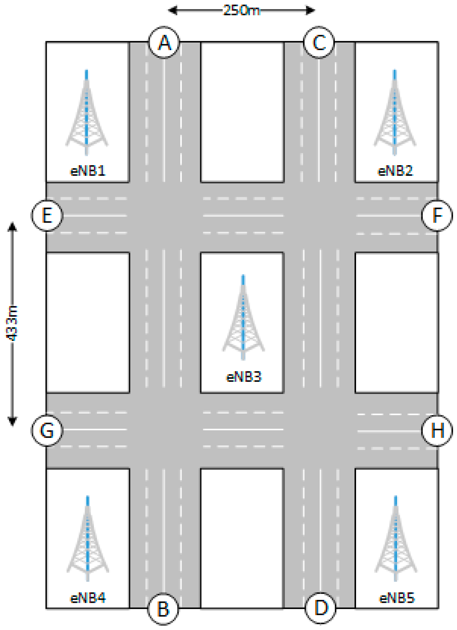
We consider the scenario depicted in Figure 26, which is taken from the 3GPP specifications [41]. The latter describes an urban scenario, defined as a grid of size 250 m × 433 m. Streets have two lanes per direction and each lane is 3.5 m wide. Inter-site distance between eNBs is 500 m. With reference to Figure 26, we defined four bidirectional vehicle flows, respectively connecting points A-B, C-D, E-F and G-H. From each entry point A to H, a new vehicle enters the network each 2.5 s. Vehicles are attached to best serving eNB according to a best-Reference-Signal-Received-Power (RSRP) criterion when they enter the grid, and they can perform handover to another eNB when they perceive a better RSRP. Vehicles moves at a speed of 60 Km/h. This means that the distance between vehicles in the same lane is 41.67 m. As shown in [42], these values for speed and distance correspond to a non-rush-hour scenario, although they are not very dissimilar to a rush-hour case, where speed and distance in the rush-hour are respectively 36 Km/h and 20 m. Physical layer parameters are the same as the previous section and presented in Table 1. We will analyze the broadcast delay with increasing target radius. For each configuration, we run a simulation for 250 s and, on each second, a randomly chosen vehicle generates one message and starts the broadcasting. Since vehicles appear in the network dynamically (hence, there are no vehicles in the network at the beginning of the simulation), we start gathering statistics after a warm-up period of 50 s.
The Trickle suppression mechanism is enabled and vehicles relay a message if they are within the target area defined within the message. MaxC/I is employed as the scheduling algorithm, hence frequency reuse is not enabled. Resource allocation is performed according to the SRA mode, which proved to be more efficient, with vehicles transmitting using CQI = 7.
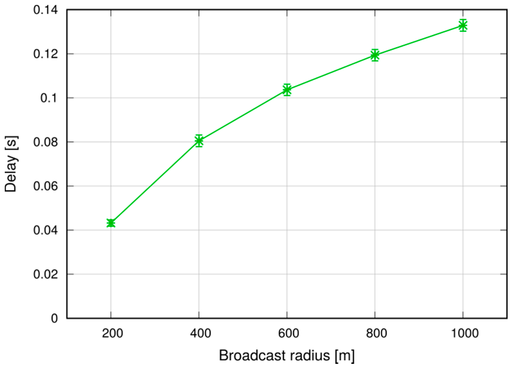
Figure 27 and Figure 28 shows respectively the average and the 95th percentile of the delay required to complete the broadcasting, as a function of the target radius.
By comparing the results with those obtained in the previous section, we can observe that both average and 95th percentile of the delay are higher in the vehicular case, although not overly so. This is due to the particular deployment of the vehicles and the definition of the target area as a circle. With reference to Figure 29, we assume that the circled vehicle (bottom right of the figure) generates a message to be broadcast within the area defined by the dashed circle. In order to reach the vehicle highlighted by the square, the message needs to traverse several hops along the roads, since it is too far to be reached with a single, direct transmission and there are no other vehicles along the straight path between them.
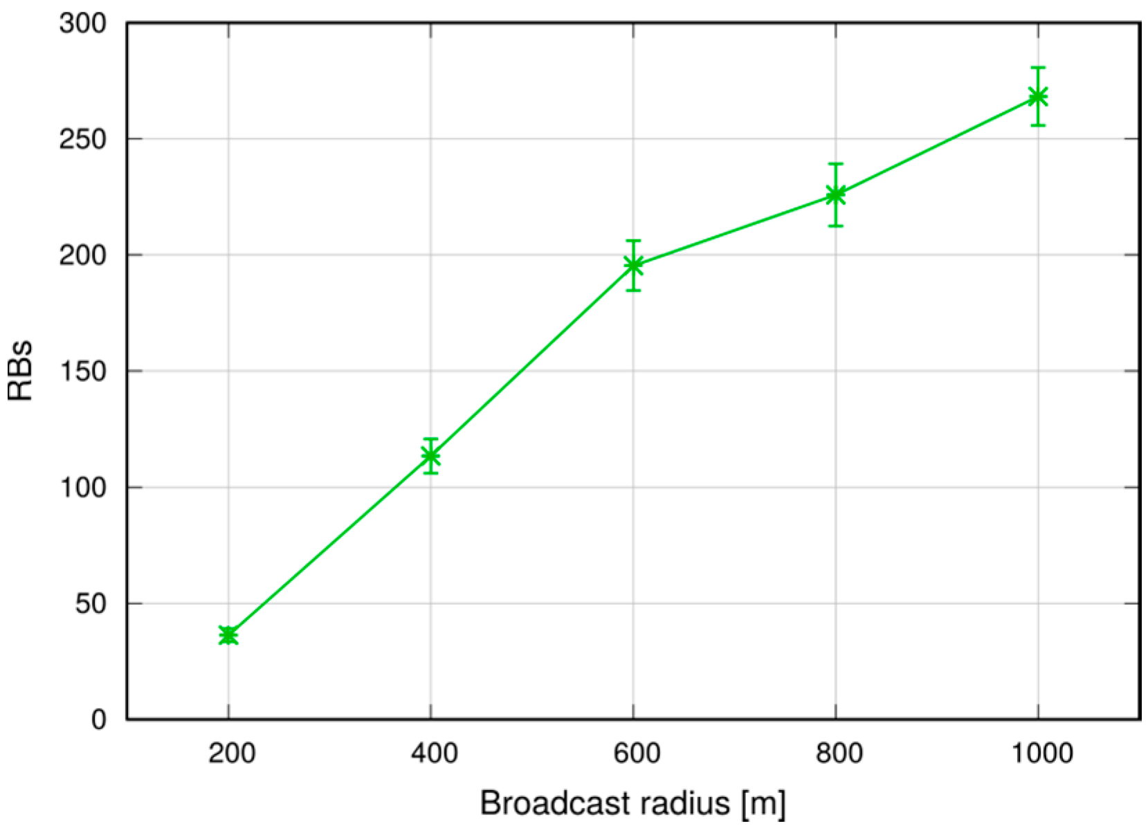
In any case, Figure 30 shows that the reliability of the dissemination is above 99%. Note that in this case vehicles are moving, hence they may enter/leave the target area while a broadcast is ongoing (although this effect is negligible in practice, given the short time it takes for a broadcast to cover the area). To maintain consistency, we count in the delivery ratio only the vehicles that are within the target area at time . Figure 31 shows that the average number of RBs allocated for each broadcast, which is around 280 for a target radius of 1000 m. In this case, too, the number of RBs used is of the same order of the number of UEs, which is quite low.
6. Conclusions
In this paper we have presented a solution for message broadcasting in LTE-A, using multihop P2MP D2D transmissions. This solution relies on application-level intelligence on the UEs, and leverages standard D2D resource allocation schemes in the network. It allows UEs to specify the target area, without being constrained by cell boundaries.
We performed simulations in both a static and a vehicular environment, in a multi-cell network. Our results show that this type of broadcast is fast, taking 80–120 ms to cover a 1000 m target radius at the 95th percentile. Moreover, it is highly reliable, meaning that the percentage of UEs actually reached by the message is close to 100%. Last, but not least, it is cheap in terms of resource consumption. In fact, it does not occupy the DL frame (the SL being carved out of the UL spectrum); this means that no service disruption occurs in the DL, and that no additional power is consumed by the eNB to support this service. Moreover, the amount of UL resources consumed is quite limited, thanks to the possibility of frequency reuse and proximate transmissions with higher CQIs. The RBs consumed for a broadcast, on average, are less than one per UE, which makes MDB quite economical, and minimally disruptive of other services that an LTE network would need to carry on simultaneously.
Further research on this topic, ongoing at the time of writing, includes at least two directions: first, investigating a deeper involvement of the infrastructure, in particular of the eNBs, in the broadcast relaying process. If the eNB is aware that a multihop transmission on the SL is being required by the sending applications, then it may allocate grants proactively to speed up the process. The second direction is to leverage network intelligence and network-wide information to characterize the target area. With reference to the vehicular case, the alert application could be made more efficient by being more selective as to which destination UEs it targets. For instance, if the message notifies that the originating vehicle is suddenly slamming on the brakes, the alert should reach the vehicles that are following it, and not those preceding it or across a block. This highlights the problem of building context-aware broadcast domains. On one hand, defining a more detailed area may occupy more space in the application-level message, which is something to consider carefully if the above-mentioned benefits are to be retained. On the other, we argue that a context-aware definition of the target area may not be defined by the vehicles themselves, since they may lack the knowledge of the surrounding environment and position of neighboring vehicles. Acquiring this knowledge using distributed means (i.e., inter vehicle communications) may not be viable either, because it would take a non-negligible message exchange and time, whereas broadcasting alerts should be accomplished in real-time to meet strict deadline requirements. The emerging MEC paradigm can play an important role in this respect. With MEC, vehicles could acquire the information about the intended geographical reach of one message by querying the corresponding service running at an application server located at the edge of the mobile network. The latter can leverage the location services provided by the network operator to define which vehicles should be receiving the message, and define a target area on behalf of the originator. Low latency would be guaranteed by the proximity of the MEC server to the vehicles, and by single client-server interaction.
Acknowledgments
The subject matter of this paper includes description of results of a joint research project carried out by Telecom Italia and the University of Pisa. Telecom Italia reserves all proprietary rights in any process, procedure, algorithm, article of manufacture, or other result of said project herein described.
Author Contributions
The three authors conceived and discussed the paper; Giovanni Nardini performed the experiments; the three authors analyzed the data; Giovanni Nardini and Giovanni Stea wrote the paper; Antonio Virdis revised and edited the paper.
Conflicts of Interest
The authors declare no conflict of interest. The funding sponsors had no role in the design of the study; in the collection, analyses, or interpretation of data; in the writing of the manuscript, and in the decision to publish the results.
References
- Zanella, A.; Bui, N.; Castellani, A.; Vangelista, L.; Zorzi, M. Internet of Things for Smart Cities. IEEE Int. Things J. 2014, 1, 22–32. [Google Scholar] [CrossRef]
- Seo, H.; Lee, K.-D.; Yasukawa, S.; Peng, Y.; Sartori, P. LTE Evolution for Vehicle-to-Everything (V2X) Services. IEEE Commun. Mag. 2016, 54, 22–28. [Google Scholar] [CrossRef]
- Chmaj, G.; Selvaraj, H. Distributed processing applications for UAV/drones: A Survey. In Progress in Systems Engineering; Springer: Cham, Switzerland, 2015; Volume 366, pp. 449–454. [Google Scholar]
- Bilstrup, K.; Uhlemann, E.; Strom, E.G.; Bilstrup, U. Evaluation of the IEEE 802.11p MAC Method for Vehicle-to-Vehicle Communication. In Proceedings of the VTC 2008-Fall IEEE 68th Vehicular Technology Conference, Calgary, BC, Canada, 21–24 September 2008; pp. 1–5. [Google Scholar] [CrossRef]
- Araniti, G.; Campolo, C.; Condoluci, M.; Iera, A.; Molinaro, A. LTE for vehicular networking: A survey. IEEE Commun. Mag. 2015, 51, 148–157. [Google Scholar] [CrossRef]
- Soleimani, H.; Boukerche, A. D2D scheme for vehicular safety applications in LTE advanced network. In Proceedings of the IEEE International Conference Communications (ICC), Paris, France, 21–25 May 2017. [Google Scholar]
- 5G-PPP. 5G PPP Use Cases and Performance Evaluation Models. White Paper. Available online: https://5g-ppp.eu/wp-content/uploads/2014/02/5G-PPP-use-cases-and-performance-evaluation-modeling_v1.0.pdf (accessed on 1 November 2017).
- ETSI GS MEC 013 v1.1.1. (2017-07): Mobile Edge Computing (MEC); Location API. Available online: http://www.etsi.org/deliver/etsi_gs/MEC/001_099/013/01.01.01_60/gs_MEC013v010101p.pdf (accessed on 1 November 2017).
- Yu, C.H.; Tirkkonen, O.; Doppler, K.; Ribeiro, C. On the Performance of Device-to-Device Underlay Communication with Simple Power Control. In Proceedings of the VTC Spring 2009—IEEE 69th Vehicular Technology Conference, Barcelona, Spain, 26–29 April 2009. [Google Scholar]
- Nardini, G.; Stea, G.; Virdis, A.; Sabella, D.; Caretti, M. Broadcasting in LTE-Advanced networks using multihop D2D communications. In Proceedings of the 2016 IEEE 27th Annual International Symposium on Personal, Indoor, and Mobile Radio Communications (PIMRC), Valencia, Spain, 4–8 September 2016. [Google Scholar] [CrossRef]
- GPP—TR 36.843 v12.0.1. Study on LTE Device-to-Device Proximity Services: Radio Aspects (Release 12). 2014. Available online: http://www.3gpp.org/ftp/Specs/archive/36_series/36.843/36843-c01.zip (accessed on 1 November 2017).
- Da Silva, J.M.B.; Fodor, G.; Maciel, T.F. Performance Analysis of Network-Assisted Two-Hop D2D Communications. In Proceedings of the Globecom Workshops (GC Wkshps), Austin, TX, USA, 8–12 December 2014. [Google Scholar]
- Wang, S.Y.; Guo, W.S.; Zhou, Z.Y.; Wu, Y.; Chu, X.L. Outage Probability for Multi-Hop D2D Communications With Shortest Path Routing. IEEE Commun. Lett. 2015, 19, 1997–2000. [Google Scholar] [CrossRef]
- Rigazzi, G.; Chiti, F.; Fantacci, R. Car Multi-hop D2D networking and resource management scheme for M2M communications over LTE-A systems. In Proceedings of the 2014 International Wireless Communications and Mobile Computing Conference (IWCMC), Nicosia, Cyprus, 4–8 August 2014. [Google Scholar]
- Militano, L.; Orsino, A.; Araniti, G.; Molinaro, A.; Iera, A. A Constrained Coalition Formation Game for Multihop D2D Content Uploading. IEEE Trans. Wirel. Commun. 2016, 15, 2012–2024. [Google Scholar] [CrossRef]
- Militano, L.; Condoluci, M.; Araniti, G.; Molinaro, A.; Iera, A.; Muntean, G.M. Single Frequency-Based Device-to-Device-Enhanced Video Delivery for Evolved Multimedia Broadcast and Multicast Services. IEEE Trans. Broadcast. 2015, 61, 263–278. [Google Scholar] [CrossRef]
- Xia, Z.; Yan, J.; Liu, Y. Energy efficiency in multicast multihop D2D networks. In Proceedings of the 2016 IEEE/CIC International Conference on Communications in China (ICCC), Chengdu, China, 27–29 July 2016. [Google Scholar]
- Lin, X.; Andrews, J.; Ghosh, A.; Ratasuk, R. An overview of 3GPP device-to-device proximity services. IEEE Commun. Mag. 2014, 52, 40–48. [Google Scholar] [CrossRef]
- Cappanera, P.; Lenzini, L.; Lori, A.; Stea, G.; Vaglini, G. Optimal joint routing and link scheduling for real-time traffic in TDMA Wireless Mesh Networks. Comput. Netw. 2013, 57, 2301–2312. [Google Scholar] [CrossRef]
- Draves, R.; Padhye, J.; Zill, B. Routing in multi-radio, multihop wireless mesh networks. In Proceedings of the Mobicom ’04—10th Annual International Conference on Mobile Computing and Networking, Philadelphia, PA, USA, 36 September–1 October 2004; ACM: New York, NY, USA, 2004. [Google Scholar]
- Williams, B.; Camp, T. Comparison of broadcasting techniques for mobile ad hoc networks. In Proceedings of the MOBIHOC ′02—3rd ACM International Symposium on Mobile Ad Hoc Networking & Computing, Lausanne, Switzerland, 9–11 June 2002. [Google Scholar]
- Kyasanur, P.; Choudhury, R.R.; Gupta, I. Smart Gossip: An Adaptive Gossip-based Broadcasting Service for Sensor Networks. In Proceedings of the 2006 IEEE International Conference on Mobile Adhoc and Sensor Systems (MASS), Vancouver, BC, Canada, 9–12 October 2006; pp. 91–100. [Google Scholar]
- Mkwawa, I.H.M.; Kouvatsos, D.D. (2011) Broadcasting Methods in MANETS: An Overview. In Kouvatsos D.D. (Eds) Network Performance Engineering. Lecture Notes in Computer Science; Springer: Berlin, Germany, 2011; Volume 5233. [Google Scholar]
- Ruiz, P.; Bouvry, P. Survey on Broadcast Algorithms for Mobile Ad Hoc Networks. ACM Comput. Surv. 2015, 48, 8. [Google Scholar] [CrossRef]
- Tseng, Y.-C.; Ni, S.-Y.; Shih, E.-Y. Adaptive approaches to relieving broadcast storms in a wireless multihop mobile ad hoc network. IEEE Trans. Comput. 2003, 52, 545–557. [Google Scholar] [CrossRef]
- Leentvaar, K.; Flint, J. The Capture Effect in FM Receivers. IEEE Trans. Commun. 1976, 24, 531–539. [Google Scholar] [CrossRef]
- Haus, M.; Waqas, M.; Ding, A.Y.; Li, Y.; Tarkoma, S.; Ott, J. Security and Privacy in Device-to-Device (D2D) Communication: A Review. IEEE Commun. Surv. Tutor. 2017, 19, 1054–1079. [Google Scholar] [CrossRef]
- Chatzopoulos, D.; Ahmadi, M.; Kosta, S.; Hui, P. Have you asked your neighbors? A Hidden Market approach for device-to-device offloading. In Proceedings of the 2016 IEEE 17th International Symposium on a World of Wireless, Mobile and Multimedia Networks (WoWMoM), Coimbra, Portugal, 21–24 June 2016. [Google Scholar]
- Chatzopoulos, D.; Ahmadi, M.; Kosta, S.; Hui, P. OPENRP: A reputation middleware for opportunistic crowd computing. IEEE Commun. Mag. 2016, 54, 115–121. [Google Scholar] [CrossRef]
- Smith, M.J.D.; Goodchild, M.F.; Longley, P. Geospatial Analysis: A Comprehensive Guide to Principles, Techniques and Software Tools; Matador: Leicester, UK, 2007. [Google Scholar]
- Levis, P.; Patel, N.; Culler, D.; Shenker, S. Trickle: A self-regulating algorithm for code propagation and maintenance in wireless sensor networks. In Proceedings of the 1st USENIX/ACM Symposium NSDI 2004, San Francisco, CA, USA, 29–31 March 2004; pp. 15–28. Available online: http://citeseerx.ist.psu.edu/viewdoc/download?doi=10.1.1.500.348&rep=rep1&type=pdf (accessed on 1 November 2017).
- Nardini, G.; Stea, G.; Virdis, A.; Sabella, D.; Caretti, M. Resource allocation for network-controlled device-to-device communications in LTE-Advanced. Wirel. Netw. 2017, 23, 787–804. [Google Scholar] [CrossRef]
- Cimmino, A.; Pecorella, T.; Fantacci, R.; Granelli, F.; Rahman, T.F.; Sacchi, C.; Carlini, C.; Harsh, P. The Role of Small Cell Technology in Future Smart City Applications. Trans. Emerg. Telecommun. Technol. 2014, 25, 11–20. [Google Scholar] [CrossRef]
- Virdis, A.; Stea, G.; Nardini, G. Simulating LTE/LTE-Advanced Networks with SimuLTE. In Advances in Intelligent Systems and Computing; Springer Nature: London, UK, 2016; Volume 402, pp. 83–105. [Google Scholar] [CrossRef]
- Varga, A.; Hornig, R. An overview of the OMNeT++ simulation environment. In Proceedings of the SIMUTools ’08—1st International Conference on Simulation Tools and Techniques for Communications, Networks and Systems & Workshops, Marseille, France, 3–7 March 2008. [Google Scholar]
- Nardini, G.; Virdis, A.; Stea, G. Simulating device-to-device communications in OMNeT++ with SimuLTE: Scenarios and configurations. In Proceedings of the 3rd OMNeT++ Community Summit, Brno, Czech, 15–16 September 2016. [Google Scholar]
- 3GPP TR 36.814 v9.0.0. Further Advancements for E-UTRA Physical Layer Aspects (Release 9). 2010. Available online: http://www.3gpp.org/ftp/Specs/archive/36_series/36.814/36814-900.zip (accessed on 1 November 2017).
- Zhou, X.; Zhang, Z.; Wang, G.; Yu, X.; Zhao, B.Y.; Zheng, H. Practical Conflict Graphs in the Wild. IEEE/ACM Trans. Netw. 2015, 23, 824–835. [Google Scholar] [CrossRef]
- Sommer, C.; German, R.; Dressler, F. Bidirectionally Coupled Network and Road Traffic Simulation for Improved IVC Analysis. IEEE Trans. Mob. Comput. 2011, 10, 3–15. [Google Scholar] [CrossRef]
- Nardini, G.; Virdis, A.; Stea, G. Simulating Cellular Communications in Vehicular Networks: Making SimuLTE Interoperable with Veins. In Proceedings of the 4th OMNeT++ Community Summit, Bremen, Germany, 7–8 September 2017. [Google Scholar]
- 3GPP TR 36.885 v14.0.0. Study on LTE-Based V2X Services (Release 14). 2016. Available online: http://www.3gpp.org/ftp/Specs/archive/36_series/36.885/36885-e00.zip (accessed on 1 November 2017).
- Wisitpongphan, N.; Bai, F.; Mudalige, P.; Sadekar, V.; Tonguz, O. Routing in Sparse Vehicular Ad Hoc Wireless Networks. IEEE J. Sel. Areas Commun. 2007, 25, 1538–1556. [Google Scholar] [CrossRef]
Figure 1.
LTE-A (Long-Term Evolution-Advanced) protocol stack. IP: Internet Protocol; PDCP: Packet Data Convergence Protocol; RLC: Radio Link Control; MAC: Media Access Control; PHY: physical.
Figure 1.
LTE-A (Long-Term Evolution-Advanced) protocol stack. IP: Internet Protocol; PDCP: Packet Data Convergence Protocol; RLC: Radio Link Control; MAC: Media Access Control; PHY: physical.

Figure 2.
(a) Scheduled Resource Allocation (SRA); (b) Autonomous Resource Selection (ARS). is the time between the generation of new data and the actual transmission. UE: User Equipment; eNB: eNodeB; RAC: Random ACcess; BSR: Buffer Status Report; TTI: Transmission Time Interval; TX: transmission.
Figure 2.
(a) Scheduled Resource Allocation (SRA); (b) Autonomous Resource Selection (ARS). is the time between the generation of new data and the actual transmission. UE: User Equipment; eNB: eNodeB; RAC: Random ACcess; BSR: Buffer Status Report; TTI: Transmission Time Interval; TX: transmission.

Figure 3.
System model.

Figure 4.
Flowchart of UE-side operations at message (msg) reception.

Figure 5.
Relaying operations at the UE application.
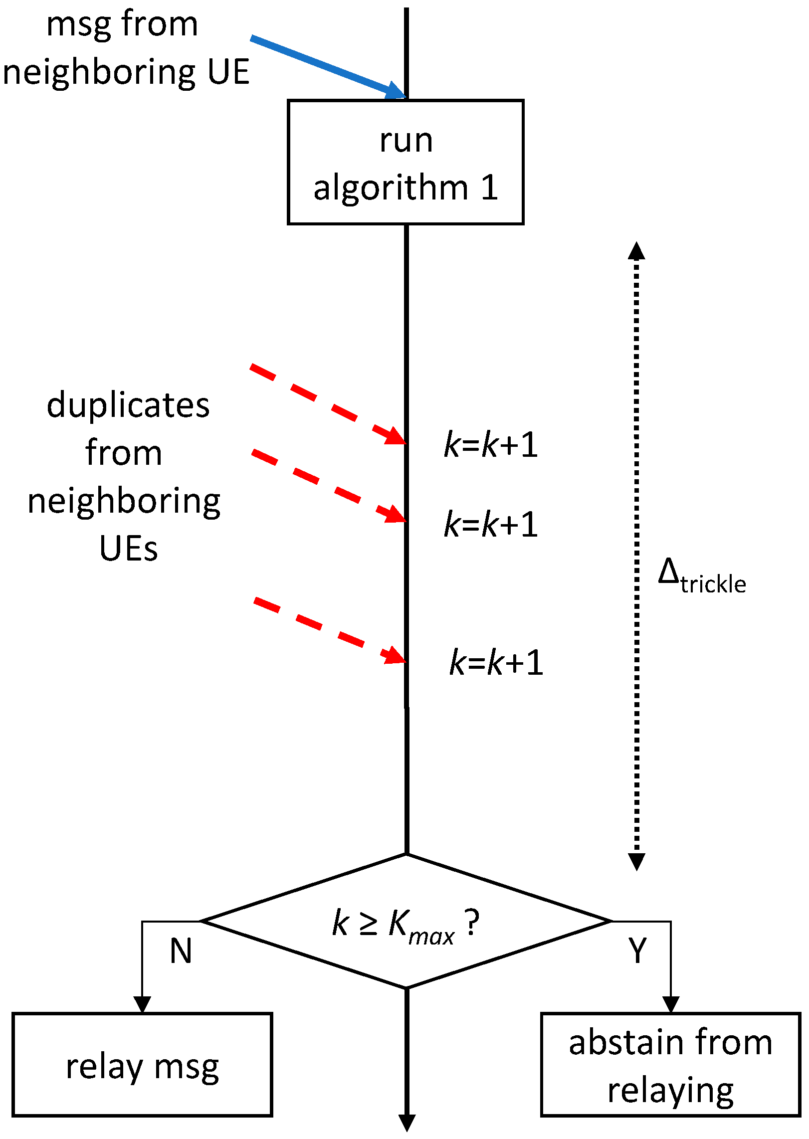
Figure 6.
Multicell scenario. UL: uplink.

Figure 7.
SRA with coordination among eNBs.

Figure 8.
Evaluation scenario.
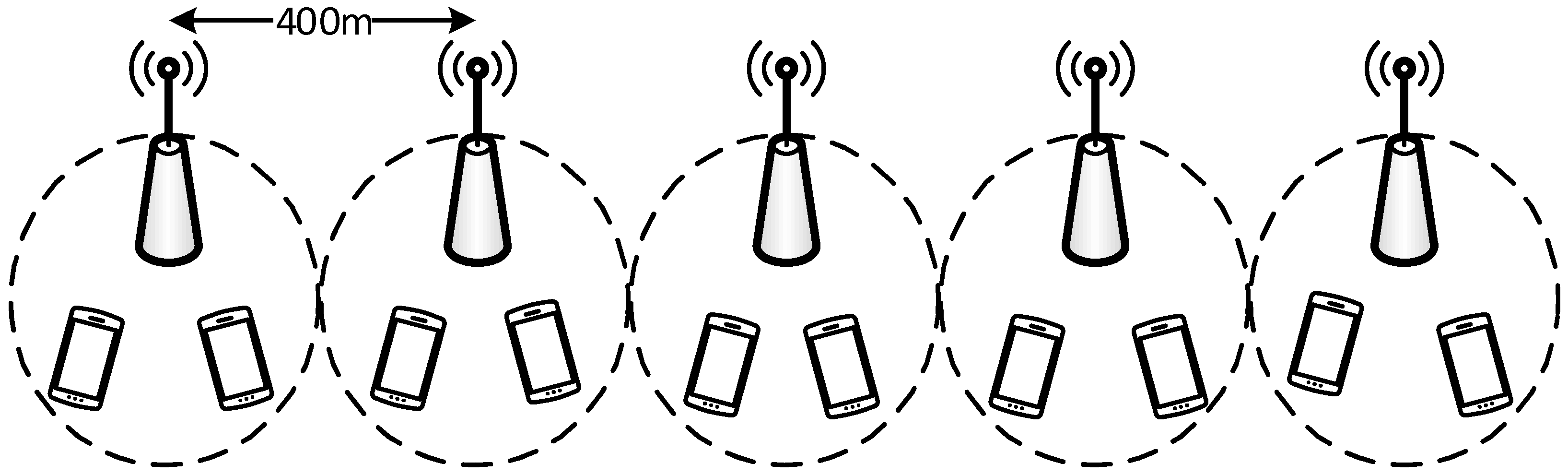
Figure 9.
Target area vs. TTL.

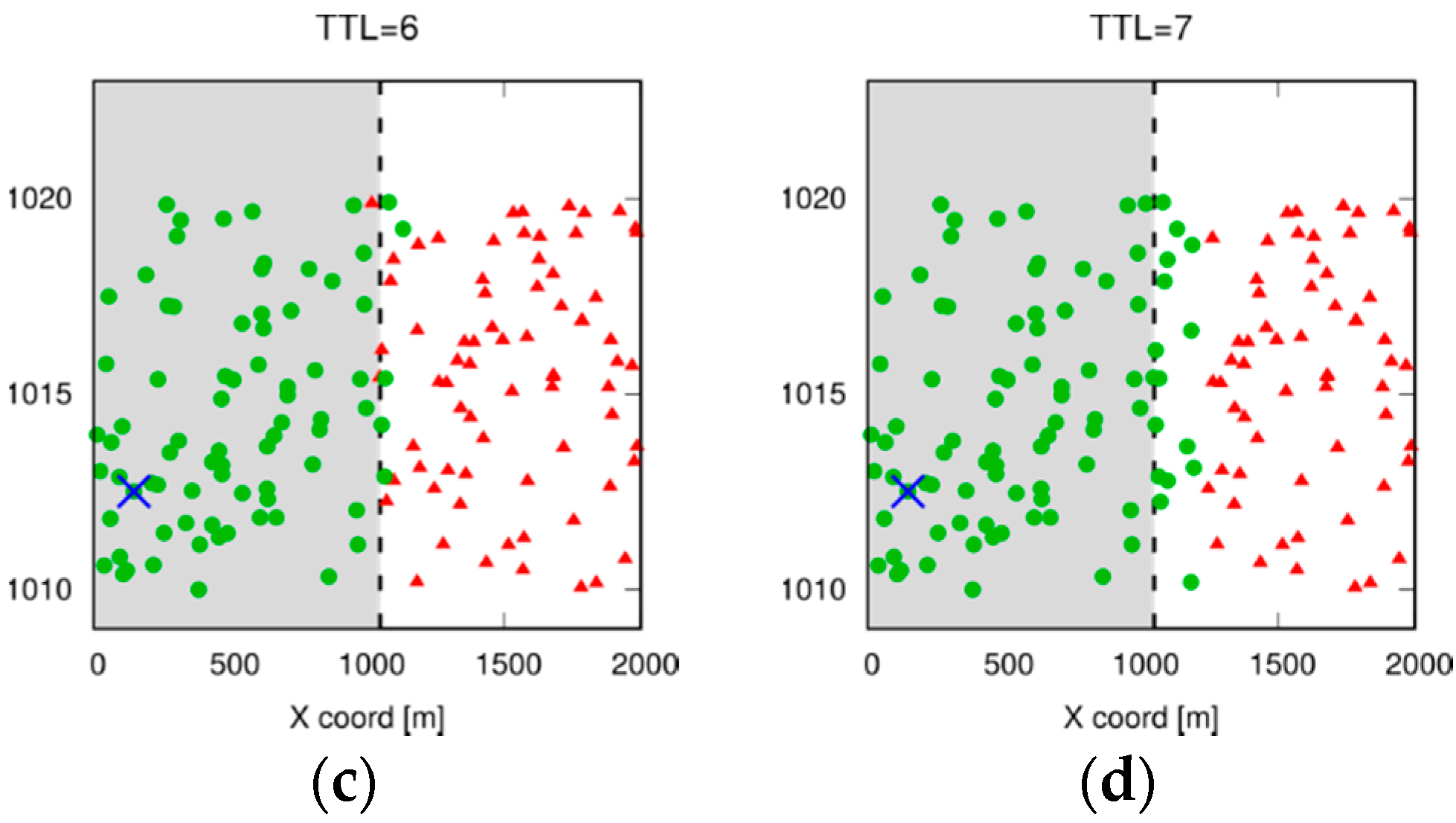
Figure 10.
RB (Resource Block) allocation at different eNBs over time.

Figure 11.
Average number of application-level transmissions with different settings of the Trickle algorithm.
Figure 11.
Average number of application-level transmissions with different settings of the Trickle algorithm.

Figure 12.
95th percentile of application-level delay with different settings of the Trickle algorithm.
Figure 12.
95th percentile of application-level delay with different settings of the Trickle algorithm.

Figure 13.
Average delay (left) and average allocated RBs (right), w and w/o Trickle.

Figure 14.
95th percentile of delay (left) and average allocated RBs in downlink (DL) (right).
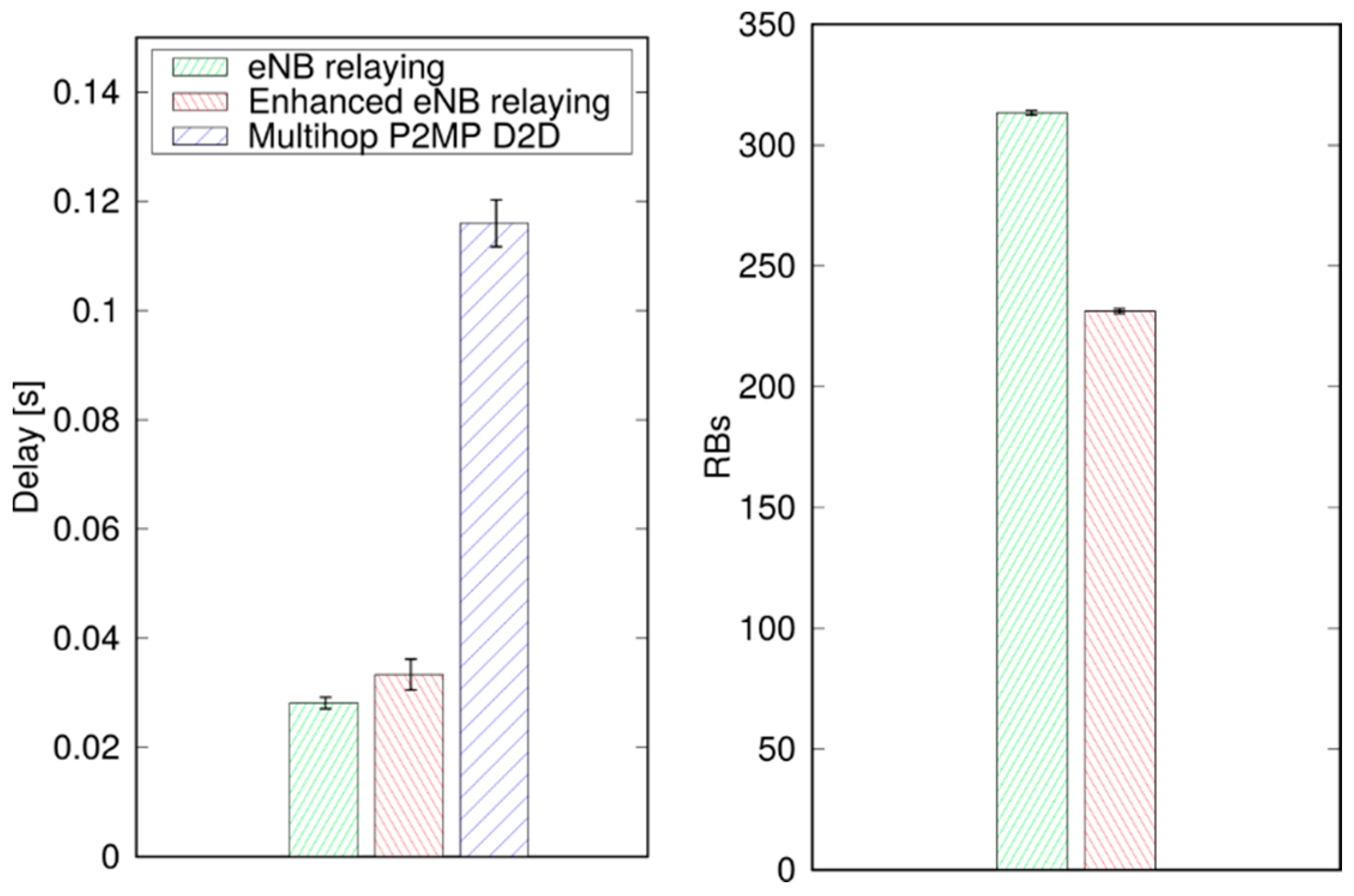
Figure 15.
Average allocated RBs and average delay as a function of CQI (Channel Quality Indicator).
Figure 15.
Average allocated RBs and average delay as a function of CQI (Channel Quality Indicator).

Figure 16.
SRA vs. ARS, average delay.
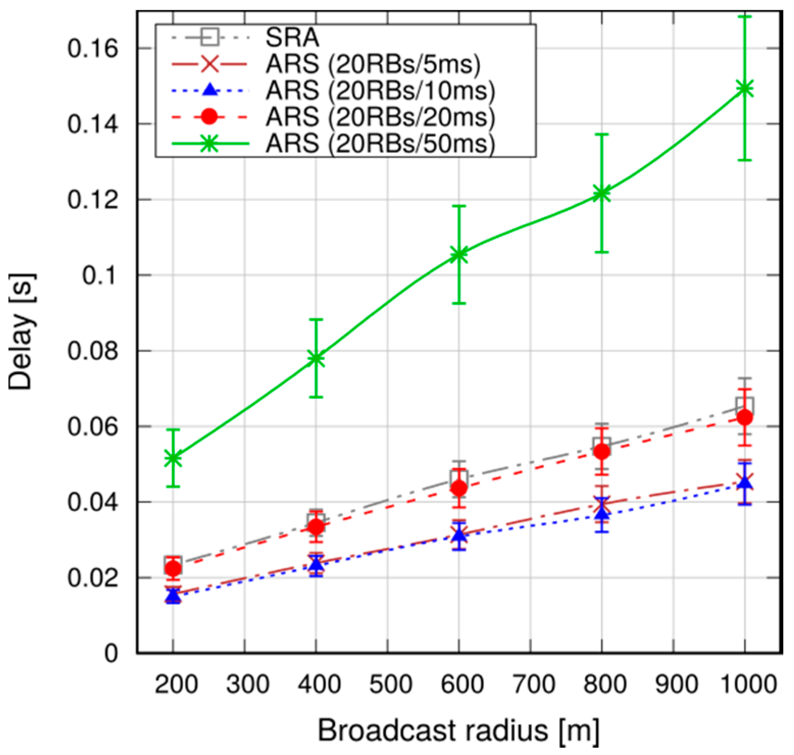
Figure 17.
SRA vs. ARS, 95th percentile of delay.
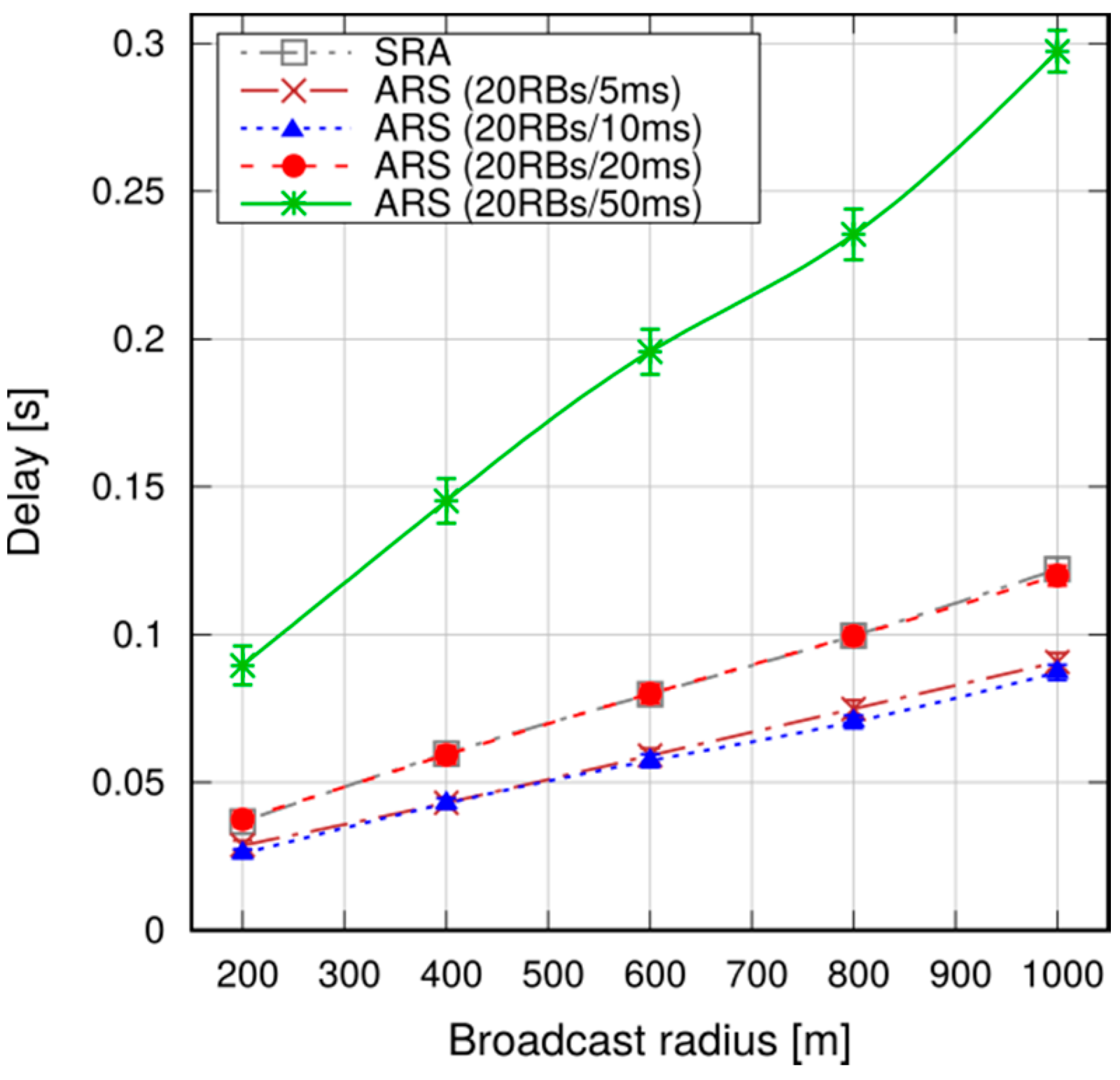
Figure 18.
SRA, avg. allocated RBs per broadcast.

Figure 19.
SRA vs. ARS, delivery ratio.

Figure 20.
95th percentile of delay with multiple broadcast sources.
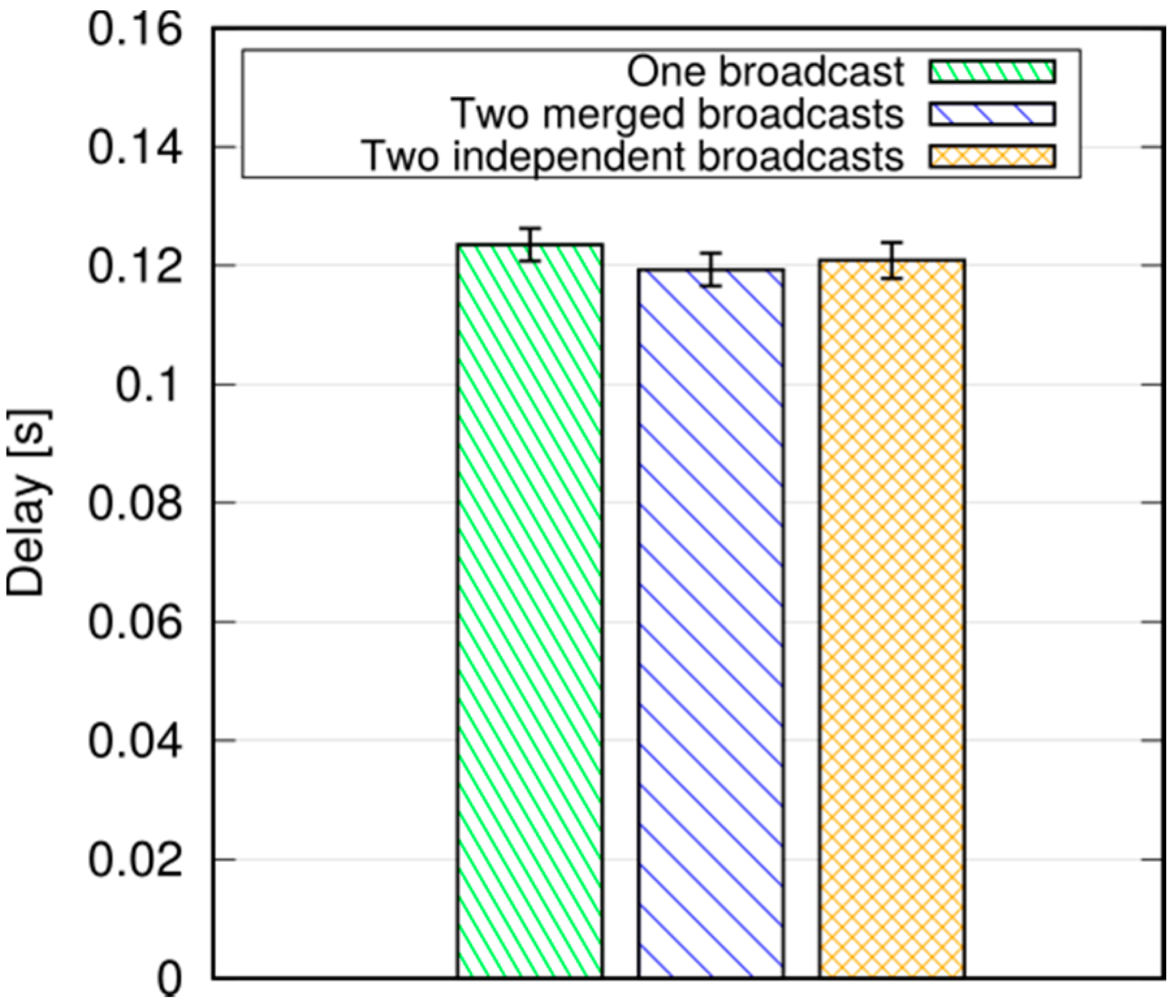
Figure 21.
Avg. allocated RBs per broadcast with multiple broadcast sources.
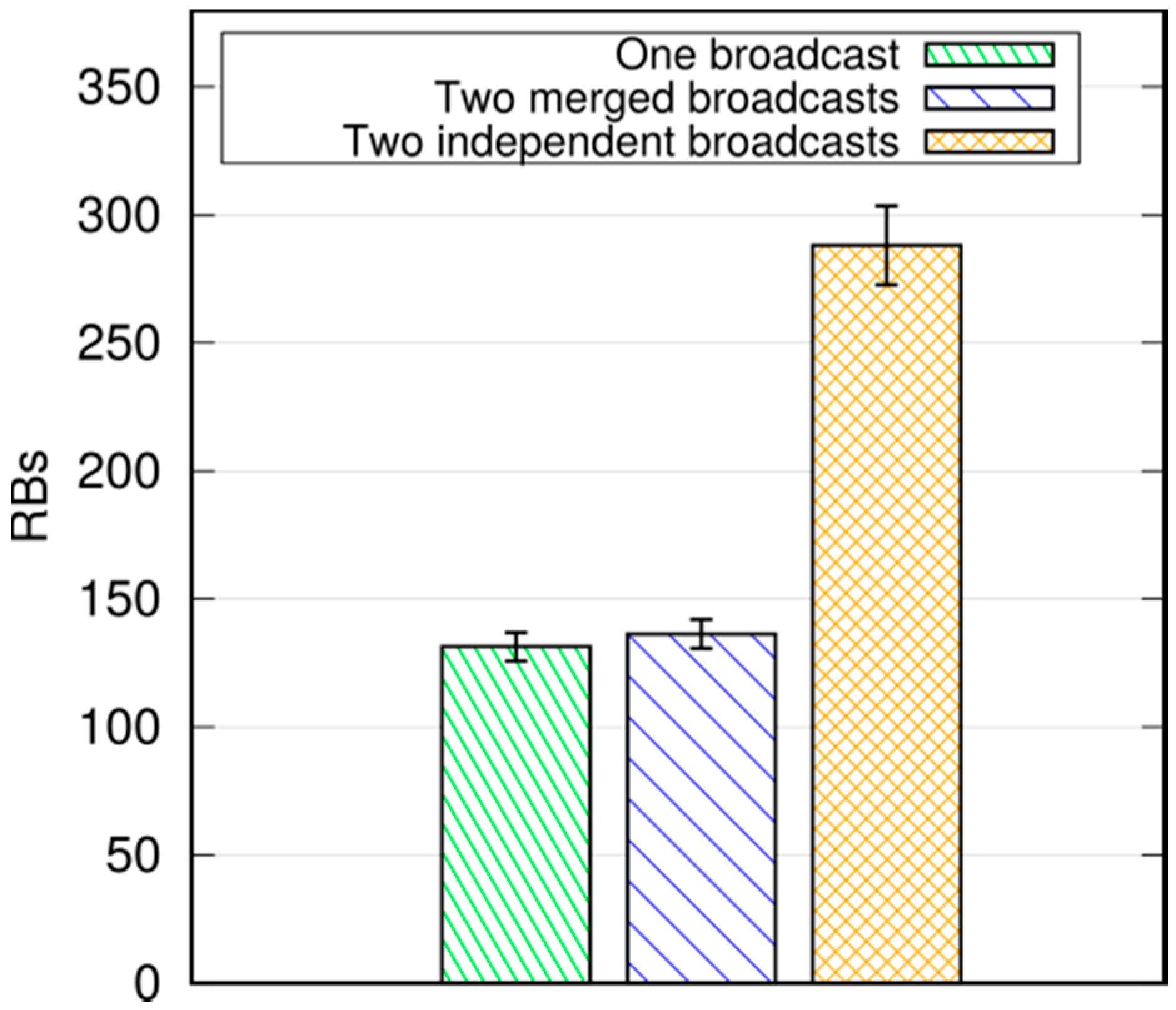
Figure 22.
95th percentile of delay, dense scenarios.
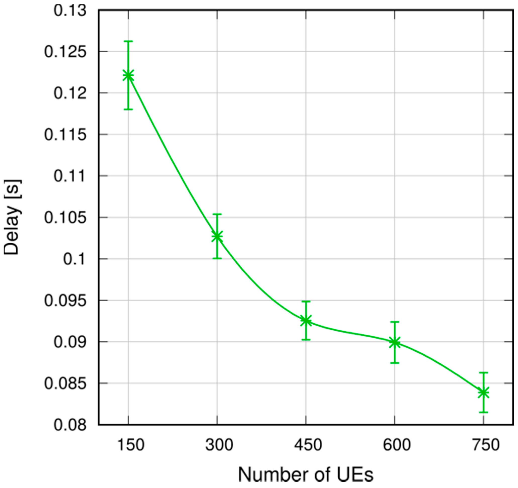
Figure 23.
Avg. allocated RBs per broadcast, dense scenarios.

Figure 24.
95th percentile of delay with non-cooperative UEs.
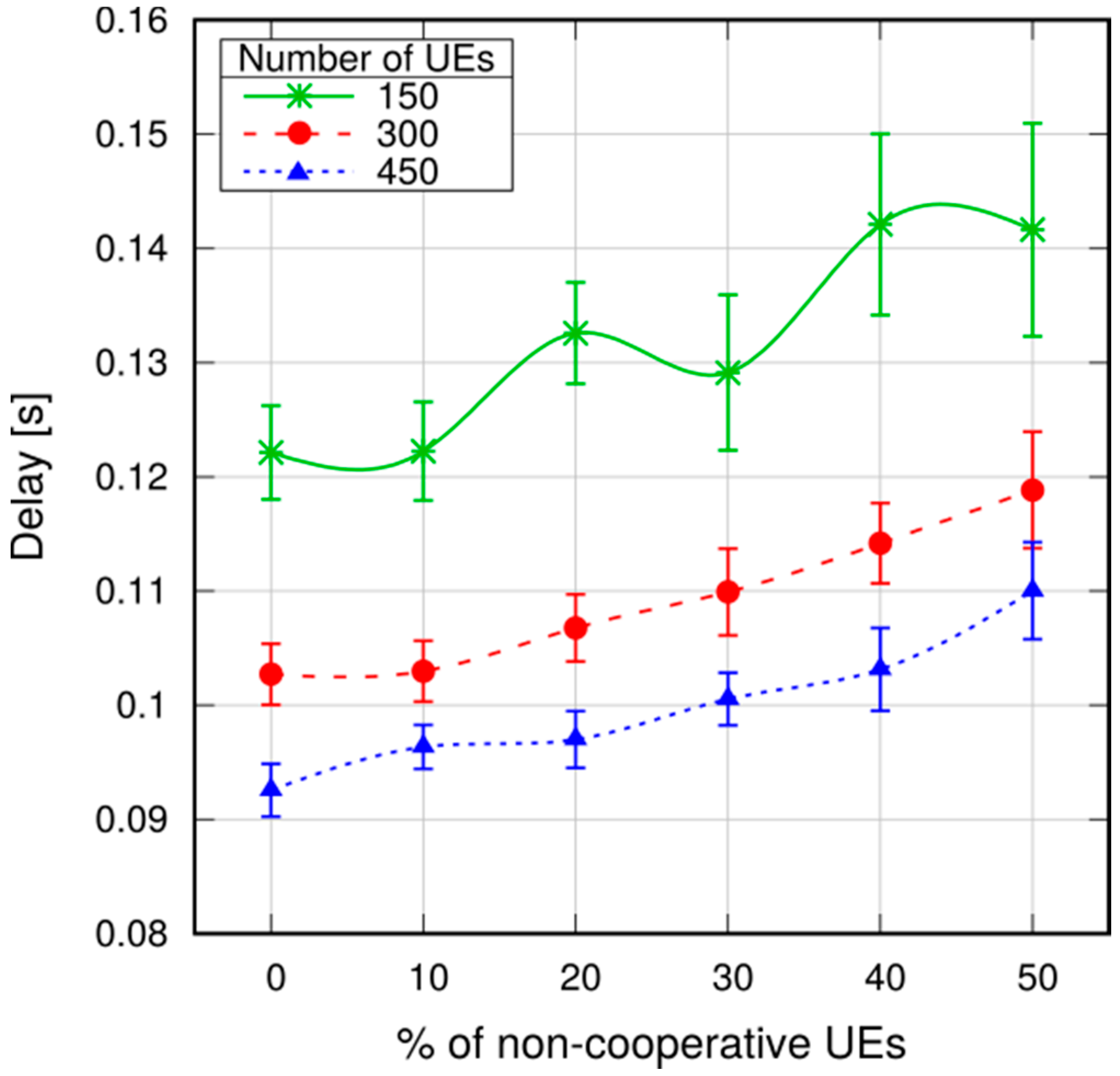
Figure 25.
Avg. allocated RBs per broadcast with non-cooperative UEs.

Figure 26.
Urban grid scenario.

Figure 27.
Average broadcasting delay.

Figure 28.
95th percentile of broadcasting delay.

Figure 29.
Example of broadcasting. The dashed circle delimits the broadcast area.
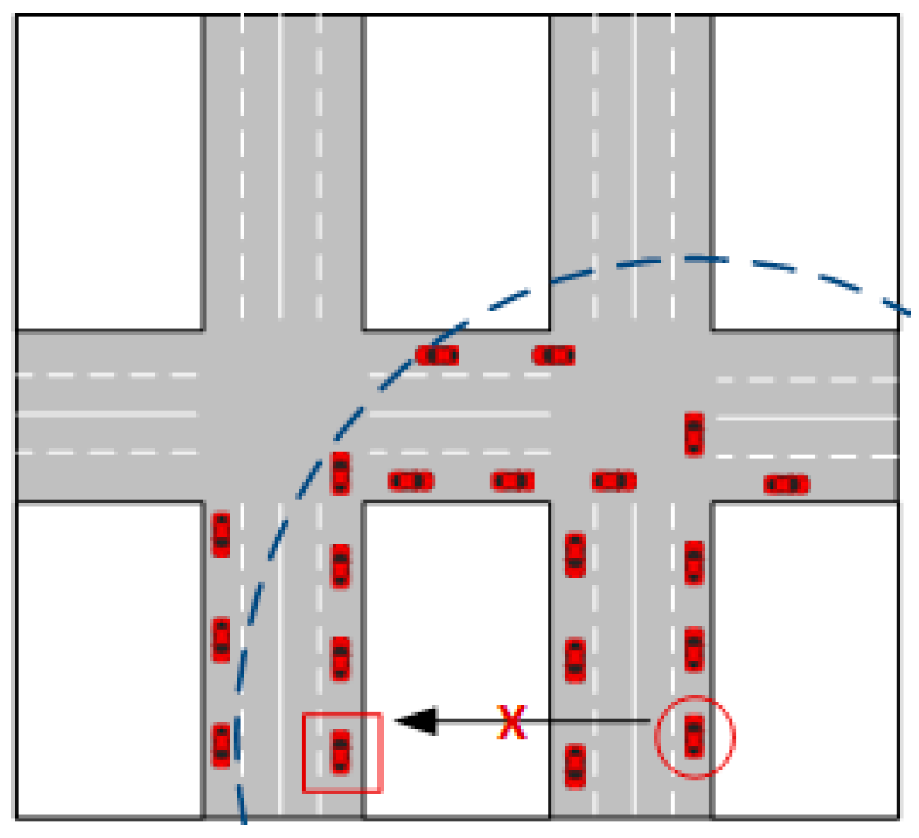
Figure 30.
Average delivery ratio.
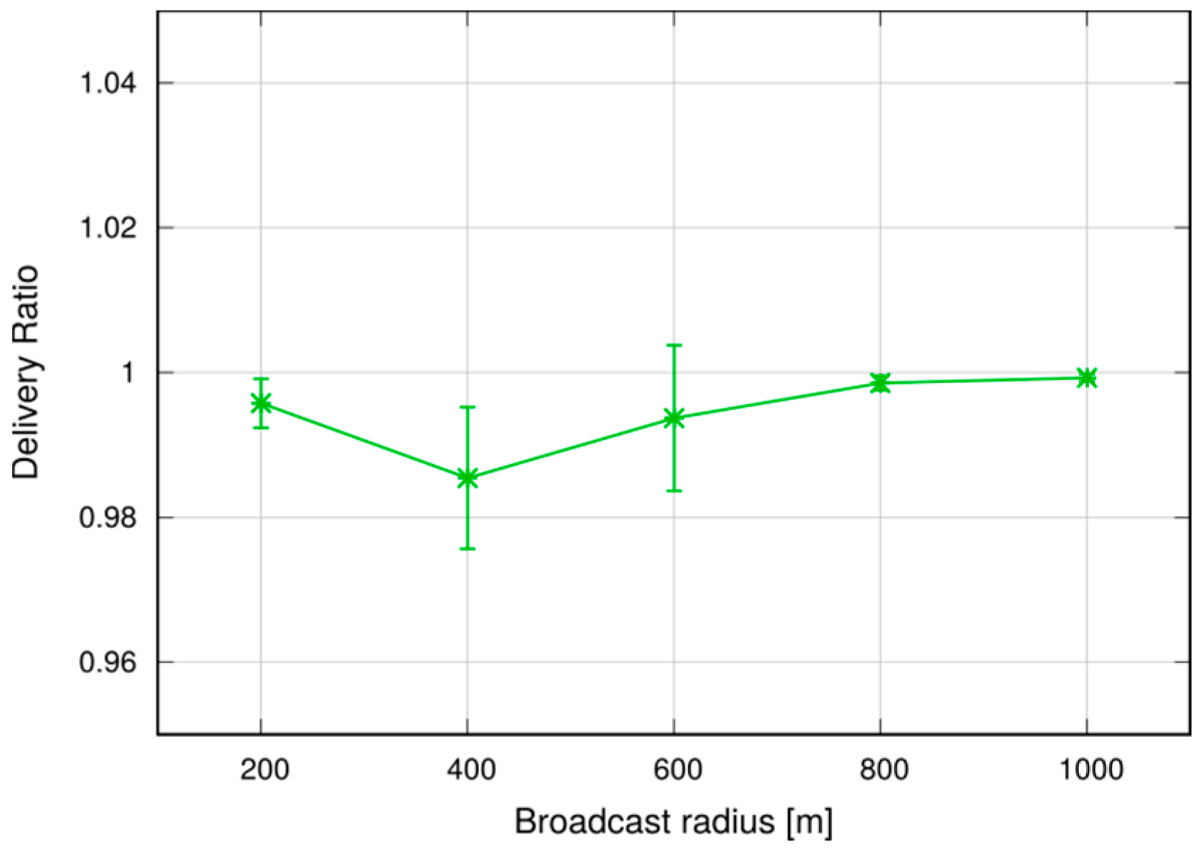
Figure 31.
Allocated RBs per broadcast.


Table 1.
Physical-layer parameters. ITU: International Telecommunication Union; eNB: eNodeB; UE: User Equipment; UL: uplink; D2D: device-to-device.
Table 1.
Physical-layer parameters. ITU: International Telecommunication Union; eNB: eNodeB; UE: User Equipment; UL: uplink; D2D: device-to-device.
| Parameter | Value |
|---|---|
| Carrier frequency | 2 GHz |
| Bandwidth | 10 MHz (50 RBs) |
| Fading model | Jakes |
| Path loss model | ITU Urban Macro [37] |
| Noise figure | 5 dB |
| Cable loss | 2 dB |
| eNB Transmission Power | 46 dBm |
| UE Transmission Power-UL | 30 dBm |
| UE Transmission Power-D2D | 15 dBm |
© 2017 by the authors. Licensee MDPI, Basel, Switzerland. This article is an open access article distributed under the terms and conditions of the Creative Commons Attribution (CC BY) license (http://creativecommons.org/licenses/by/4.0/).
Share and Cite
MDPI and ACS Style
Nardini, G.; Stea, G.; Virdis, A. A Fast and Reliable Broadcast Service for LTE-Advanced Exploiting Multihop Device-to-Device Transmissions. Future Internet 2017, 9, 89. https://doi.org/10.3390/fi9040089
AMA Style
Nardini G, Stea G, Virdis A. A Fast and Reliable Broadcast Service for LTE-Advanced Exploiting Multihop Device-to-Device Transmissions. Future Internet. 2017; 9(4):89. https://doi.org/10.3390/fi9040089
Chicago/Turabian StyleNardini, Giovanni, Giovanni Stea, and Antonio Virdis. 2017. "A Fast and Reliable Broadcast Service for LTE-Advanced Exploiting Multihop Device-to-Device Transmissions" Future Internet 9, no. 4: 89. https://doi.org/10.3390/fi9040089
Note that from the first issue of 2016, this journal uses article numbers instead of page numbers. See further details here.