Simulation Model for Productivity Analysis of External Insulated Precast Concrete Wall System


1
School of Civil, Environmental and Architectural Engineering, Korea University, Seoul 02841, Korea
2
Research and Development Center, Hyundai Development Company, Gwangju, Gyeonggi-do 12750, Korea
*
Author to whom correspondence should be addressed.
Sustainability 2018, 10(1), 105; https://doi.org/10.3390/su10010105
Submission received: 5 December 2017
/
Revised: 22 December 2017
/
Accepted: 29 December 2017
/
Published: 4 January 2018
Abstract
:External Insulation Finishing System (EIFS) is recognized as a suitable method for attaining energy efficiency of buildings. However, conventional EIFS is not actively applied to building construction due to additional time and cost compared with interior insulation method. Therefore, as an alternative that can contribute to active utilization of the external insulation system, this study proposes an External Insulated Precast Concrete (PC) Wall System and its simulation for performing productivity analysis. Results of this study are as follows: (1) an external insulated PC-Wall system is developed of which its insulation performance is above 40% higher than that of the conventional EIFS; (2) performance of the developed system satisfied American Standards for Testing of Materials (ASTM) and American Architectural Manufacturers Association (AAMA) standards; (3) applicability of the developed system is verified via test-bed with construction time lapsing about 40 min for each PC-Wall; and (4) CYCLONE modeling methodology is employed to perform productivity analysis of the developed system compared with conventional EIFS.
1. Introduction
1.1. Research Background and Purpose
External Insulation Finishing System (EIFS) is an effective construction method for achieving energy efficiency of buildings by installing insulation board at the outer wall of a building [1,2,3,4,5]. The system is especially applied to high-rise residential buildings nowadays, since concrete in the interior space of building can sustain heat due to the heat storage effect when EIFS is activated [6,7,8,9]. Furthermore, the system can eliminate thermal bridge between wall and slab, which was always recognized as a problem to be resolved in case internal insulation method is adopted. Compared to internal insulation method, external insulation method can decrease annual heating energy requirement of residential building by 10.2% and cooling energy requirement by 1.3% [3,10]. Outstanding performance on energy efficiency of the external insulation method resulted in an increasing spotlight of the system.
Despite numerous advantages, however, EIFS method is not yet applied extensively to building construction for several reasons. Firstly, conventional EIFS is constructed after the framework process of a building construction. Not only is it inevitable to install a temporary facility such as gondola and scaffolding for insulation work but also problems related to construction period and cost increase and safety issues arise [11,12,13]. Secondly, external insulation work is composed of complex construction process, in which laborers perform insulation work at the outer space inside gondolas. Outdoor work performed under unsafe conditions lead to reduction in productivity and increase in risk of safety accidents. These problems serve as obstacles to activation of the external insulation method. Currently, internal insulation method is applied to the insulation of apartment buildings, during which the thickness of the insulation board increases in order to minimize energy loss.
Increase in the thickness of insulation material, however, only leads to reduction of the interior space whilst thermal bridge between the wall and the slab cannot be fundamentally blocked by merely reinforcing the material dimension. Since external insulation method is essential for satisfying the energy conservation demand of the apartment complex proposed by the government in Korea, it is essential that improvement of the construction method to solve the obstacles to the application of external insulation method be considered [14,15].
Various researches on external insulation method have been proposed since interests on securing insulation performance of walls have increased as probable solutions for achieving energy savings of buildings. Studies on verifying the excellence of external insulation method in terms of energy efficiency, LCC (Life-Cycle Cost) and construction period through comparative analysis of internal and external insulation methods have been consistently proposed [16,17,18,19,20]. In recent years, studies have been conducted to evaluate the heat transfer rate and airtightness of the external insulation method applied to the Passivhaus—a voluntary standard for energy efficiency in a building that recommends annual heating and cooling demands to be less than 15 kWh/m2 and the total specific heat load as less than 10 W/m2 [21,22,23,24,25,26,27]. In addition, various researches have been carried out to improve the external insulation method in terms of determining the optimal insulation material thickness in order to secure the insulation performance considering the characteristics of the construction industry of various countries, their regional conditions and climatic conditions [28,29,30,31,32,33,34].
However, most of the researches on insulation methods so far have been conducted under the purpose of improving the sandwich panel method that are actively applied for low-rise buildings construction [35,36,37,38,39] and approached the external insulation system in terms of thermal engineering and building materials. Studies conducted for improving the construction aspect of external insulation system are highly limited. Researches that attempted to combine the existing construction technology and external insulation method to support maximum productivity through minimizing the input of construction workers on site and the work processes have not yet been proposed.
Therefore, an external insulated PC-Wall system that combines Precast Concrete (PC) wall and external insulation system is developed in this study as an innovative technology to replace the existing external insulation system. Also, applicability test and productivity analysis are performed in addition to the basic performance evaluation in order to verify the potential utilization of the proposed system.
1.2. Research Scope and Methodology
This study is performed with purpose on the development of an external insulated PC-Wall, performance evaluation of the developed system for use as a wall, evaluation of applicability via test-bed and productivity analysis based on work process analysis.
This study is conducted based on the following steps:
• Development of external insulated PC-Wall
The developed wall system enables minimization of the number of people at the construction site and to simplification of on-site assembly process by manufacturing the walls in factory. Also, the developed wall structure attains a Passivhaus level insulation and light-weight compared to existing systems.
• Performance evaluation of PC-Wall
External insulated PC-Wall system is evaluated to satisfy performance requirements based on the following criteria: air leakage, water penetration, structural performance, residual deformation and interlayer displacement.
• Evaluation of test-bed applicability of PC-Wall
A test-bed was conducted to evaluate the field applicability of the developed wall system.
• Productivity evaluation of PC-Wall
Based on the results of the process analysis of test-bed, on-site productivity of the external insulated PC-Wall was analyzed and compared with that of the conventional internal insulation method.
2. Conventional Insulation Methods Compared with the Proposed PC Wall System
2.1. Internal Insulation Method
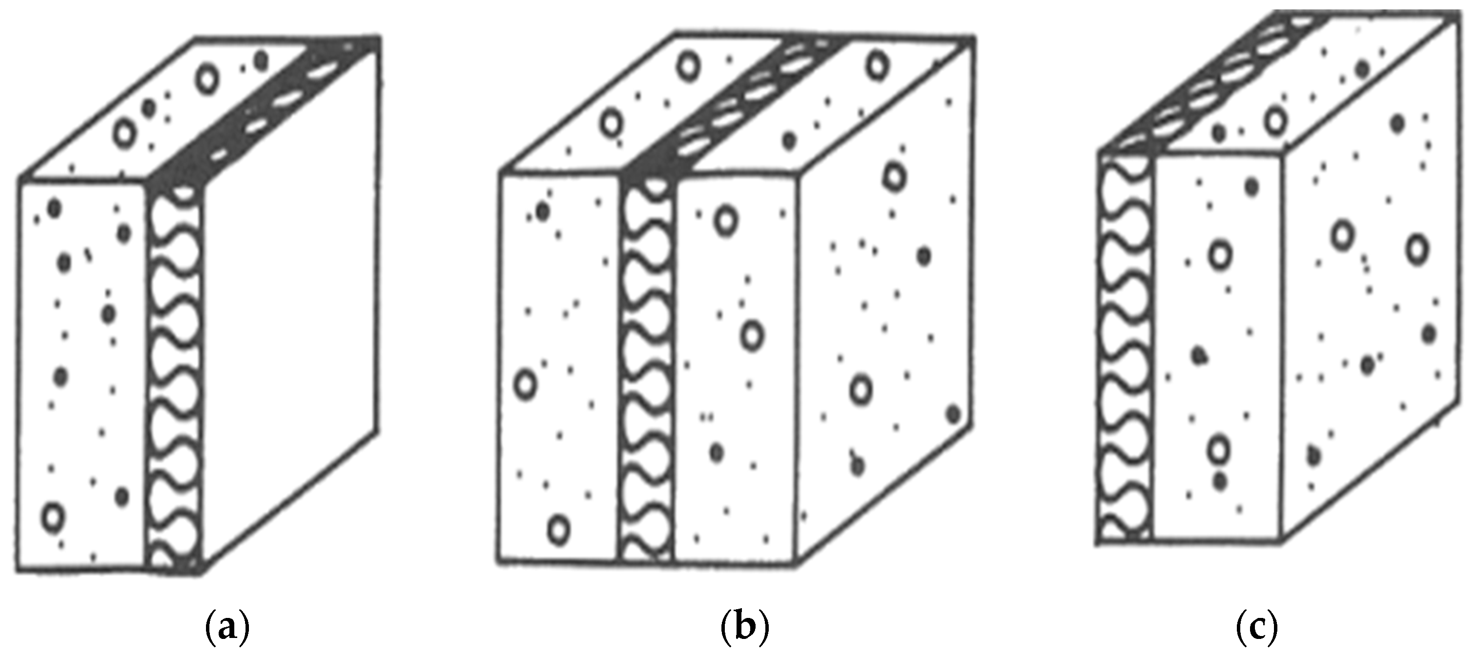
Internal insulation system, in which the insulation board is attached on the internal part of the structure, is applied to majority of apartment houses in Korea as shown in Figure 1. This method, however, inevitably generates thermal bridges due to discontinuity of materials in the wall-slab and wall-wall joints. Also, other problems such as energy loss and condensation occur.
2.2. Insulated Concrete Sandwich Panel Method
Insulated concrete sandwich panel is an insulation method in which insulation board is sandwiched between the inner and outer walls. It is necessary to verify the composite behavior of the inner and outer walls to resist the shear force generated by wind load in order to apply the sandwich panel method. Problems to be resolved for applying the sandwich panel include the local thermal bridging phenomenon through the shear joint and reduced thermal insulation performance. Sandwich panel is not actively applied in apartment housing in Korea due to difficulty of manufacturing the wall, increased wall thickness and uneconomical factors.
2.3. Conventional External Insulation Method
External insulation finishing system (EIFS) is a construction method in which mortar is used as an adhesive and the insulation is attached to the outer wall of the structure. Despite the advantages including excellent energy efficiency and prevention of indoor space loss compared to internal insulation, external insulation method has drawbacks such as low adhesion of insulation and concrete wall and unsafe working environment due to external construction. In addition, since the bonding process is made under wet construction method, external insulation is prone to construction delay due to the influence of precipitation and moisture.
2.4. External Insulated Precast Concrete (PC)-Wall System
A deviation from the existing post-attachment method was needed in order to overcome the problems caused by the conventional wet construction of external insulation. This study proposed an external insulated Precast Concrete (PC)-Wall system (hereinafter referred to as “PC-Wall system”) based on a completely new design by applying precast (dry method) technique to the external insulation method. Precast method is a method in which walls are manufactured at a factory, transported to the site and then assembled. Performance of this dry construction method has already been verified in terms of life-cycle cost, fire safety and durability through previous studies [39,40,41,42]. Applying the PC method to existing external insulation method through simplified and standardized production process is expected to solve problems related to increase in construction period and unsafe working environment.
External insulated PC-Wall system is designed to have insulation board of high thermal insulation performance be assembled in a pre-fabricated concrete wall in the factory to meet Passivhaus energy performance standards. Expanded Polystyrene (EPS), an insulation board with excellent adhesion between concrete and finishing material, is used for developing the wall system. Each layer of the wall system is integrated without using any adhesive through the use of fixture and heat insulation cap. As a result, the PC-Wall maintains the same thickness as that of the existing method, while achieving improved thermal insulation performance and energy saving efficiency.
3. Development of External Insulated PC-Wall System
3.1. Schemes for Developing External Insulated PC-Wall
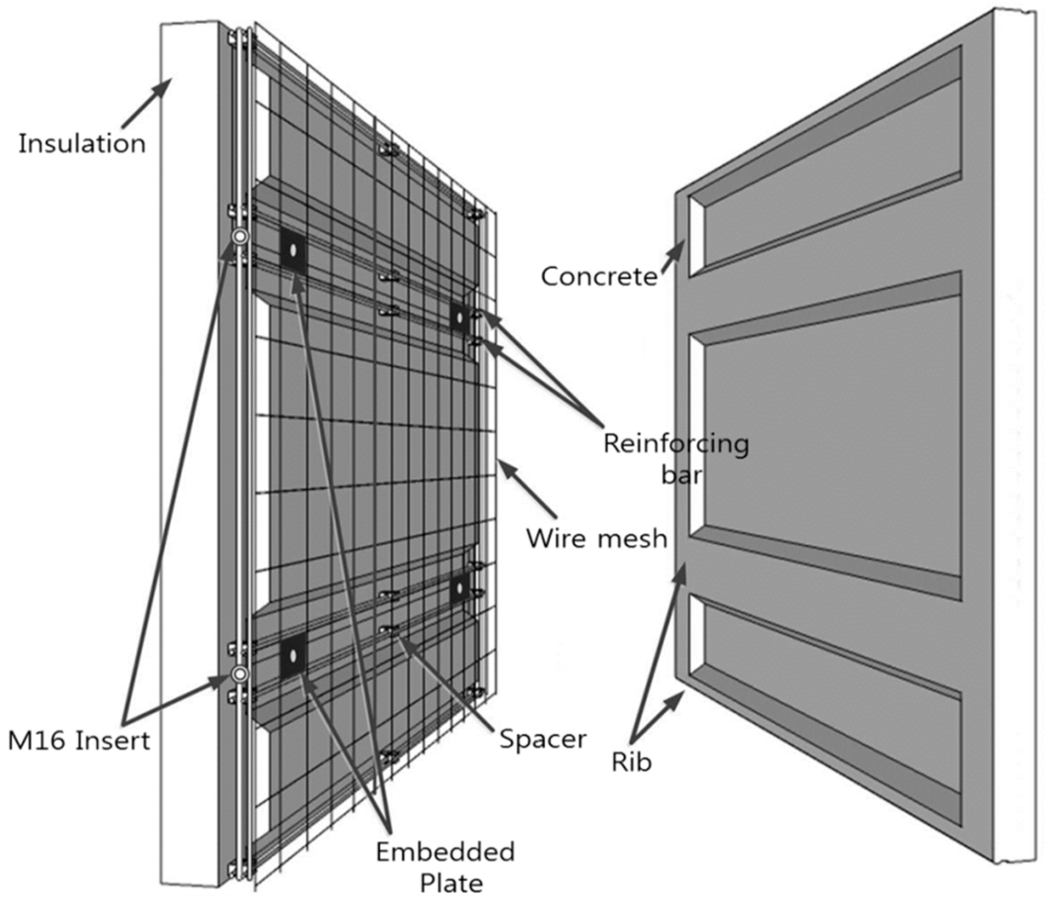
External insulated PC-Wall system is manufactured at the factory, of which the prefabricated wall is further installed on-site for structuring a building. The developed system integrates external insulation method and precast concrete wall, insulation and finishing material as shown in Figure 2 below. Wall components are integrated by the adhesive force between each material without using an adhesive as accessory. Furthermore, the PVC (Polyvinyl Chloride) fixture is secured with a bolt, denoted as a supporting pin on Figure 2 below, is installed to improve the physical bonding force between concrete and insulation board.
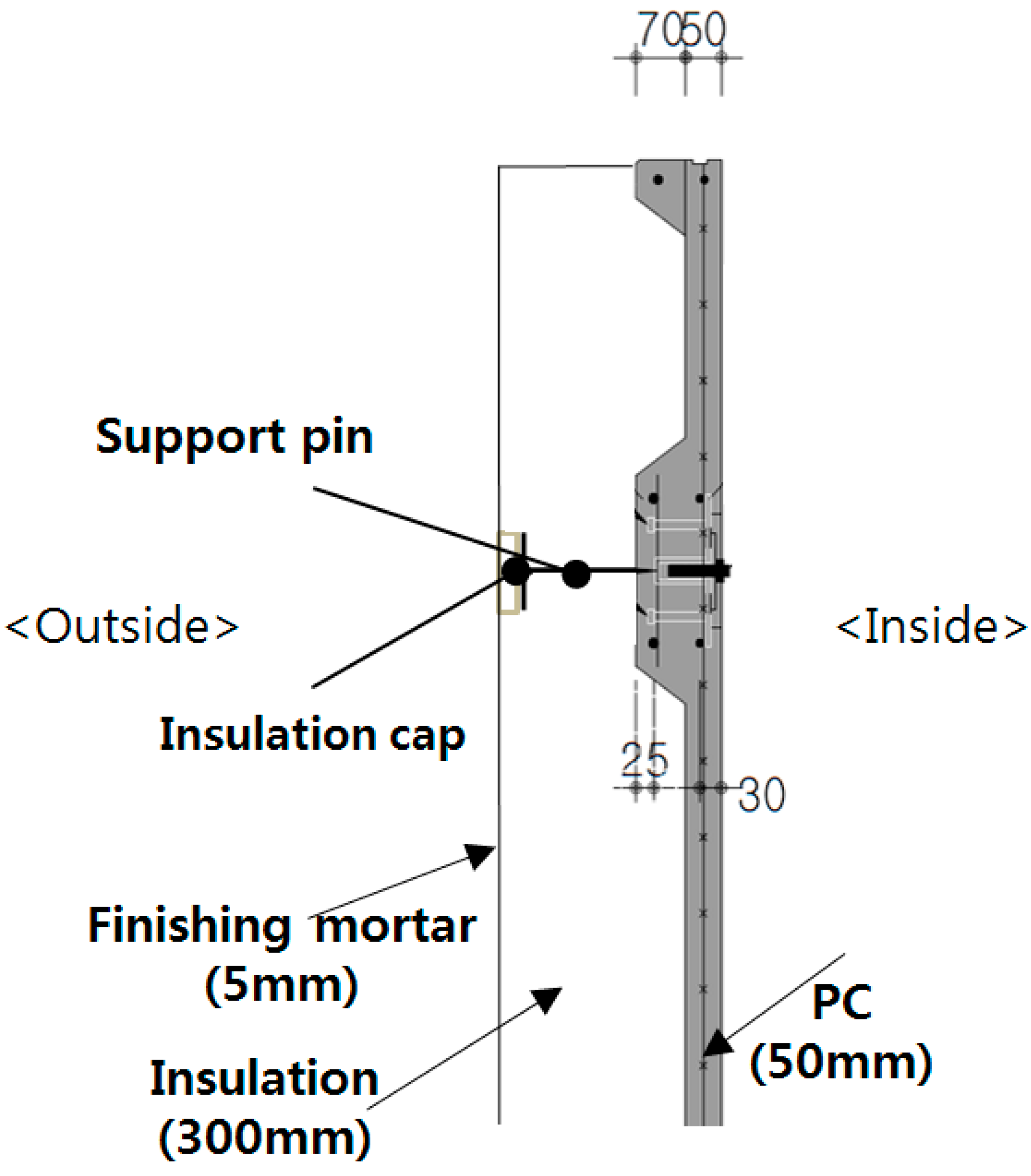
The specimen was designed and manufactured as shown in Figure 3 to verify the basic performance of the external insulated PC-Wall. EPS insulation with a thickness of 300 mm was bonded to a concrete wall with a thickness of 50 mm by using a PVC fixture and a 5 mm thickness mortar was applied as a finishing material.
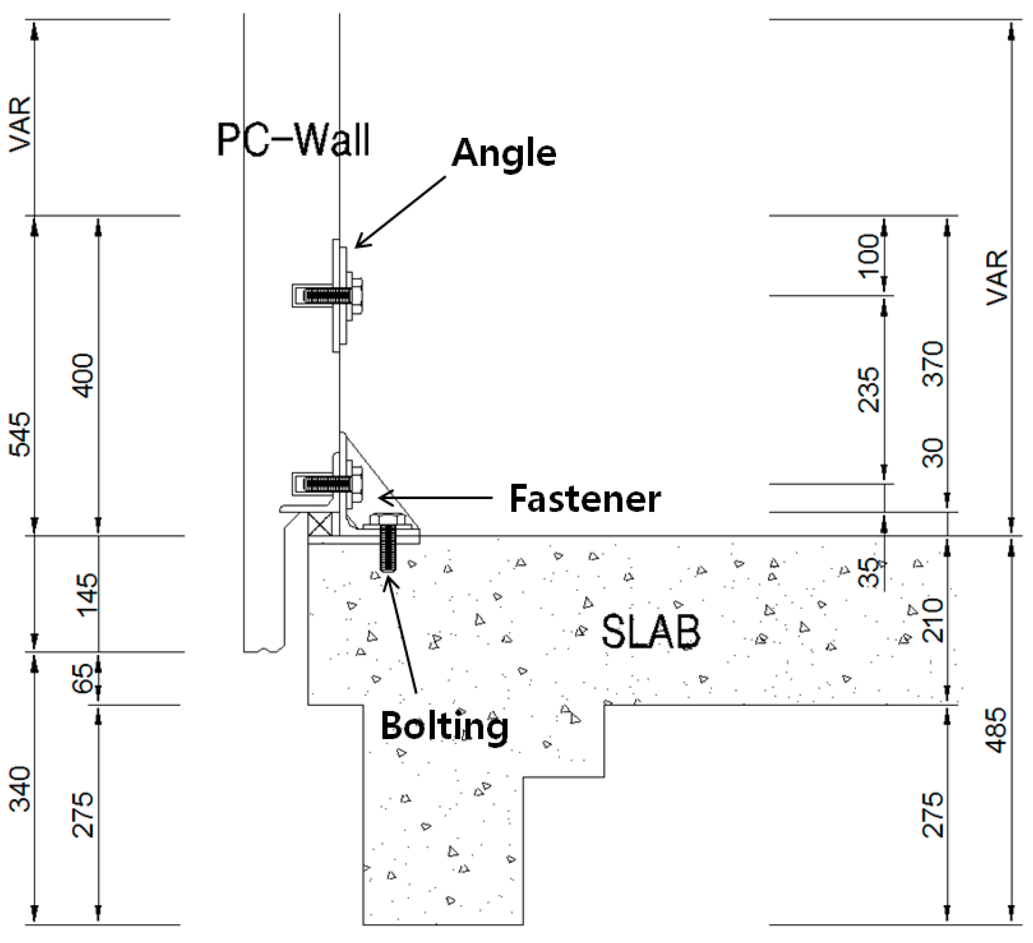
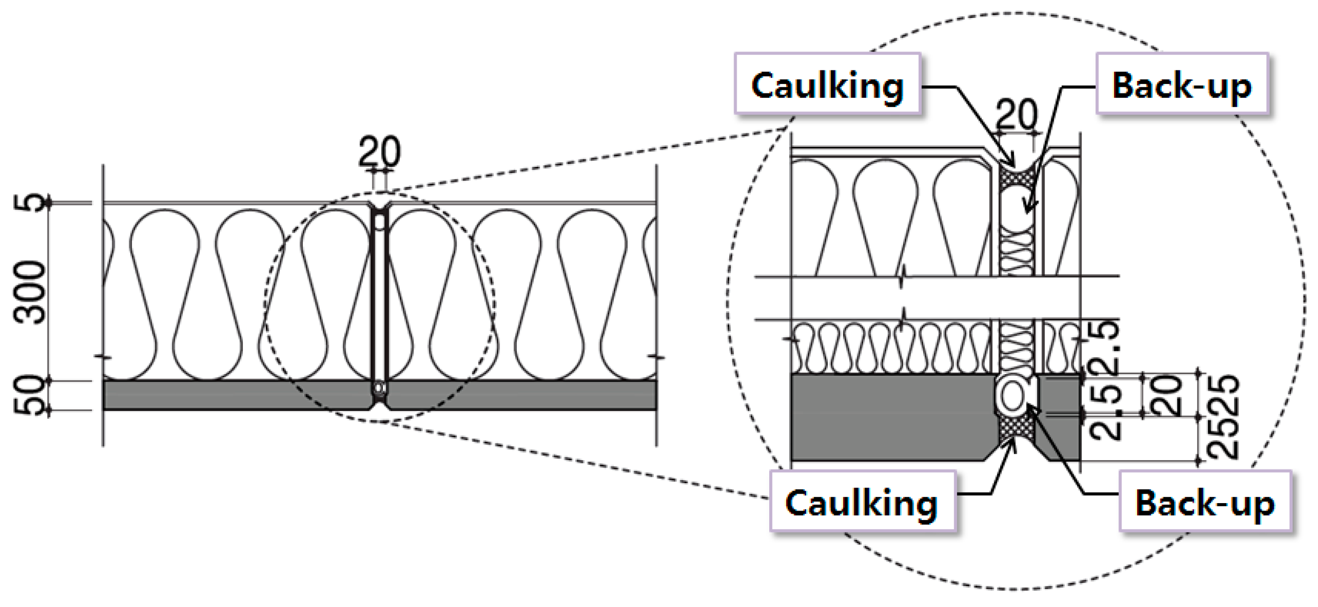
The joint between the PC-Wall and the slab was bolted using a fastener as shown in Figure 4. Angles were installed to adjust the vertical and horizontal spacing between members. Also, as depicted on Figure 5, PC joints filled with urethane foam for minimizing thermal bridge. Interior and exterior of walls were closed with a backing agent and caulking.
Meanwhile, Table 1 shows the insulation performance of the external insulated PC-Wall compared to that of the existing Reinforce Concrete (RC) wall in terms of thermal conductivity and resistance to heat transmission, weight of each unitized wall and their thickness. U-values in terms of thermal conductivity and resistance to heat transmission for each material compositing the conventional RC-Wall, which are values standardized by a decree from Construction Act in Korea, were calculated for comparison with those of the proposed wall system. The values for the proposed PC-wall system were calculated by applying PHYSIBEL program (Physibel, Maldegem, Belgium), a program that can evaluate multi-dimensional heat transfer analysis under ISO-interpreted standard codes with high accuracy and feasibility.
It was concluded after a rational analysis of the two wall systems that the proposed PC-wall system yields superior results in terms of total resistance of heat transmission (8.691 m2·K/W) by 43.3% compared to that of RC-wall (4.925 m2·K/W), U-value (0.2 W/m2·K) by 42.5% compared to that of the RC-wall (0.115 W/m2·K) and weight (190 kg/m2) by 47.2% compared to that of the RC-wall (360 kg/m2).
It was analyzed that the external insulated PC-Wall has outstanding insulation performance by 42.5% compared to that of the existing RC wall and that the concrete thickness can be reduced by 150 mm, thereby achieving a weight reduction of about 47.2%. Therefore, it is shown that the PC-Wall method is an eco-friendly method that can sustain energy and reduce carbon emissions by cost reduction and insulation performance improvement due to reduction of concrete and steel bar use.
3.2. Performance Evaluation of External Insulated PC-Wall System
3.2.1. Performance Evaluation Method and Outline
• Performance Evaluation Method
A pre-construction mock-up test was conducted to verify the overall performance of External Insulated PC-Wall. Since mock-ups are effective tools not only to verify design and performance but also for logistics of project installation procedures, results of the test were vital for concretization of the proposed wall system.
Procedures on performing basic and complex mock-up test are based on ASTM (American Standards for Testing of Materials) and AAMA (American Architectural Manufacturers Association) worldwide performance standards for enhancing confidence in quality of outputs [40,41,42,43,44,45,46]. For the evaluation of the proposed wall system, air-tightness, water-tightness, structural performance, residual deformation and interstory drift were selected as evaluation criteria for verifying performance of the proposed wall system.
• Performance Evaluation Summary
The mock-up test was executed in KCL (Korean Conformity Laboratories), which upholds high standards in testing, inspection and certification of construction materials, energy and environmental products in Korea. The test was carried out using four walls with each size of 2.2 m (width) × 2.8 m (height). Positive pressure (+) with 206.20 kgf/m2 (57.44 m/s) and negative pressure (−) with 515.60 kgf/m2 (90.83 m/s) were applied throughout the test in order to satisfy the basic lab conditions.
3.2.2. Air-Tightness
Air-tightness test is performed to measure the amount of air leakage from wall after maintaining the pressure of +7.6 kgf/m2. Test on air leakage follows the standard pressure specified in ASTM E283-04. The results of the airtightness test are shown in Table 2.
The results of the airtightness test showed that the airtightness was about 12 times less than the allowable value, indicating that the developed wall system satisfies performance requirement on air-tightness.
3.2.3. Water-Tightness
Resistance to water penetration is another fundamental criterion for determining performance of an external wall system. This part of test is conducted in accordance to two standards—ASTM E331-00 for verifying its resistance on water penetration under uniform static air pressure difference and AAMA 501.1-05 for verifying its performance under dynamic pressure.
The static water penetration test is structured to check the occurrence of water leakage by spraying water of pressure 204 L/m2 per hour for 15 min while maintaining a static, positive pressure by 20% of the designed wind load.
AAMA standard allows the static pressure to be given within a range of 30.4 kgf/m2 and 73.2 kgf/m2. Static pressure for verification of the developed system was initially 41.24 kgf/m2, which corresponds to values proposed by the standards. After 20% of the test elapsed, the pressure value was increased to maximum in order to verify its performance against the most adverse conditions. As indicated on Table 3, no leakage was observed in the two tests, thereby being judged that the developed PC-wall system satisfies the allowable value.
3.2.4. Structural Performance
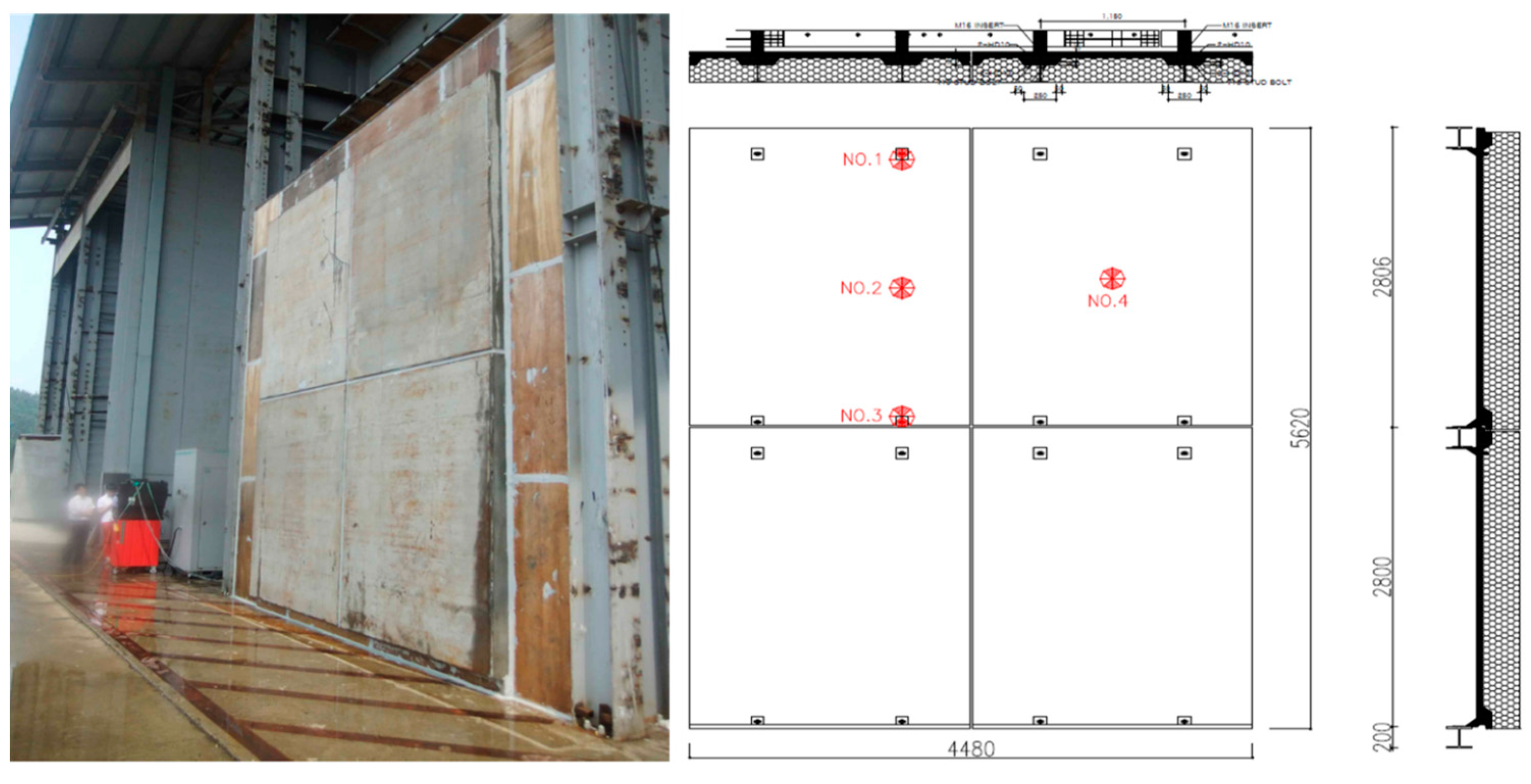
Structural performance test is a critical aspect of a structure to measure the maximum displacement of each point after maintaining the pressure by 50%, 100% (both positive and negative pressure) of the design wind pressure on the wall for 10 seconds based on ASTM E330-02. A displacement gauge was installed at each point on the wall as shown in Figure 6 to compare the measured values with the permissible values.
The allowable values are calculated as L/360 (L: distance between points) according to the standard specification of the Ministry of Land, Infrastructure and Transport (MOLIT) of Korea. The test pressure for this test is shown in Table 4 below.
The measured values in Table 4 show maximum displacement of 0.42 (vertical) and 0.02 mm (horizontal) under positive pressure and maximum of 1.08 mm (vertical) and 0.21 mm (horizontal) at negative pressure, respectively. As a result of satisfying the allowable value of this test, it was judged that the stability against the wind load was sufficiently secured.
3.2.5. Residual Deformation
The residual deformation test was carried out by maintaining the pressure of 75% and 150% (static and negative) of the design wind pressure on the wall for 10 seconds according to ASTM E330-20 and then removing the pressure again to measure the remaining displacement in each wall.
The measured values in Table 5 are the maximum residual deformation occurred in the specimen of the PC-wall when the static and negative pressures act on the wall. The measured values were derived as a maximum of 0.02 mm (vertical) and 0.08 mm (horizontal) under positive deformation and 0.02 mm (vertical) and 0.10 mm (horizontal) under negative pressure. As a result of the test, it is concluded that the specimen met the desired levels of structural reliability. The adequacy of the structural design of the developed PC-wall is satisfied, in which the safety of the wall against deformation is secured after the load is applied.
3.2.6. Inter-Story Drift
Inter-story drift is an evaluation criterion intended to observe the performance of the systems when subjected to specified horizontal displacements in the plane. The test on inter-story drift based on AAMA 501.4-09 complements to test on changes in serviceability of wall system specimen (including air infiltration, water penetration resistance and structural integrity) by providing information on racking displacements.
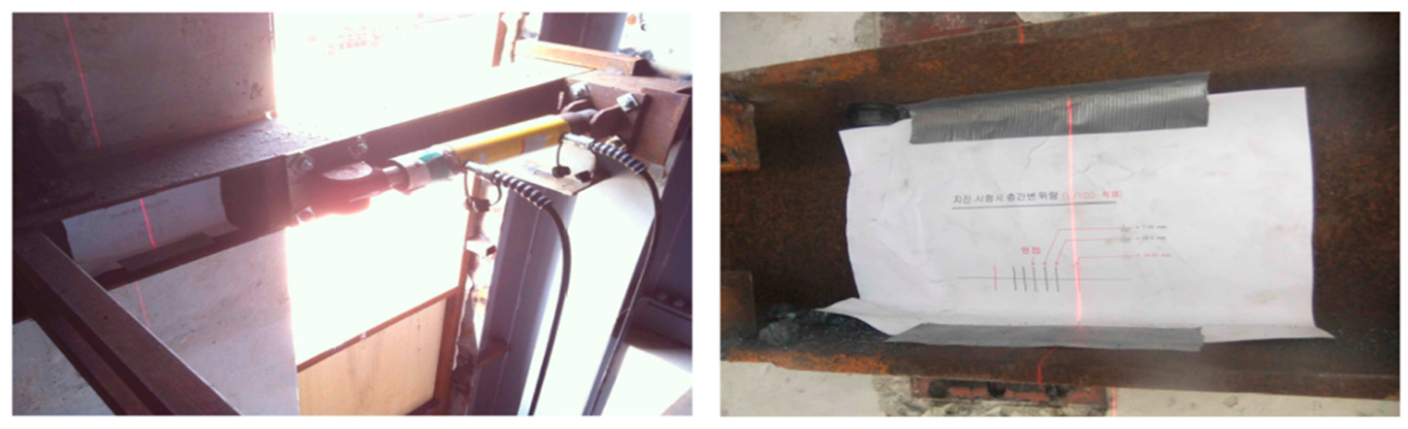
Since this test is recommended for evaluating wall systems subjected to seismic and wind-induced inter-story drifts, an earthquake load resistance test is performed by applying displacements to the left and right of the horizontal axis based on the originating point. The displacement measurement is measured by a drift gauge as shown in Figure 7. This test was carried out two times, yielding the results of L/400 (7.0 mm) for the first test and L/100 (28.0 mm) for the second test.
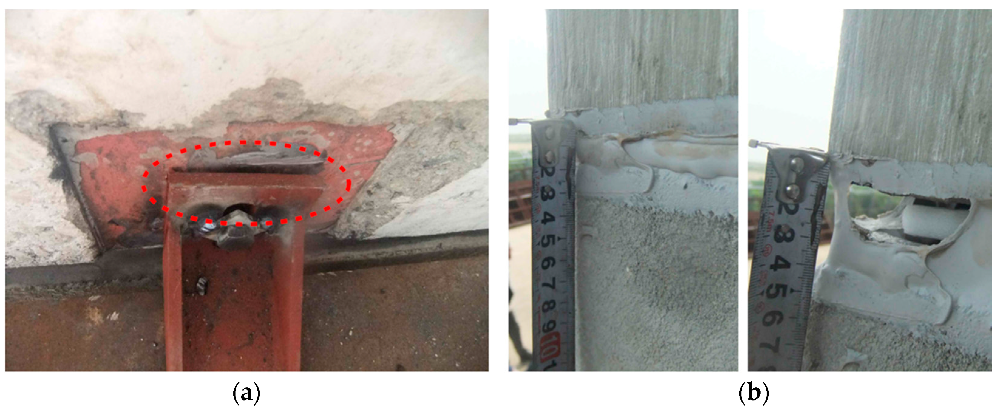
The results of both test, first and second, must satisfy the allowable values so that the developed specimen can be further utilized as a part of a building. Test #1, as depicted on Table 6, was satisfactory for all three building applications under a result of 7 mm displacement. However, under the deflection of 28 mm on Test #2, a damage on horizontal joint and disappearance of a fastener were occurred as shown in Figure 8. This part of the result insinuates that the specimen developed as a pre-construction mock-up cannot be applied to a construction with the purpose of “essential facility”. However, since the applied target of the PC-Wall developed in this study—apartment as a residential building corresponds to the classification “high occupancy assembly”, it can be concluded that there is no problem in applying the developed model to apartment houses.
4. Applicability & Productivity Evaluation of External Insulated PC-Wall System
4.1. Applicability Assessment
In the previous section, performance evaluation on various aspects of the external insulated PC-Wall system was performed. Taking all the results from pre-construction mock-up test into consideration, a test-bed was performed to verify the field applicability and workability of PC-Wall method and to evaluate on-site productivity. Table 7 shows the outline of the test-bed for evaluating and verifying the applicability of the proposed system.
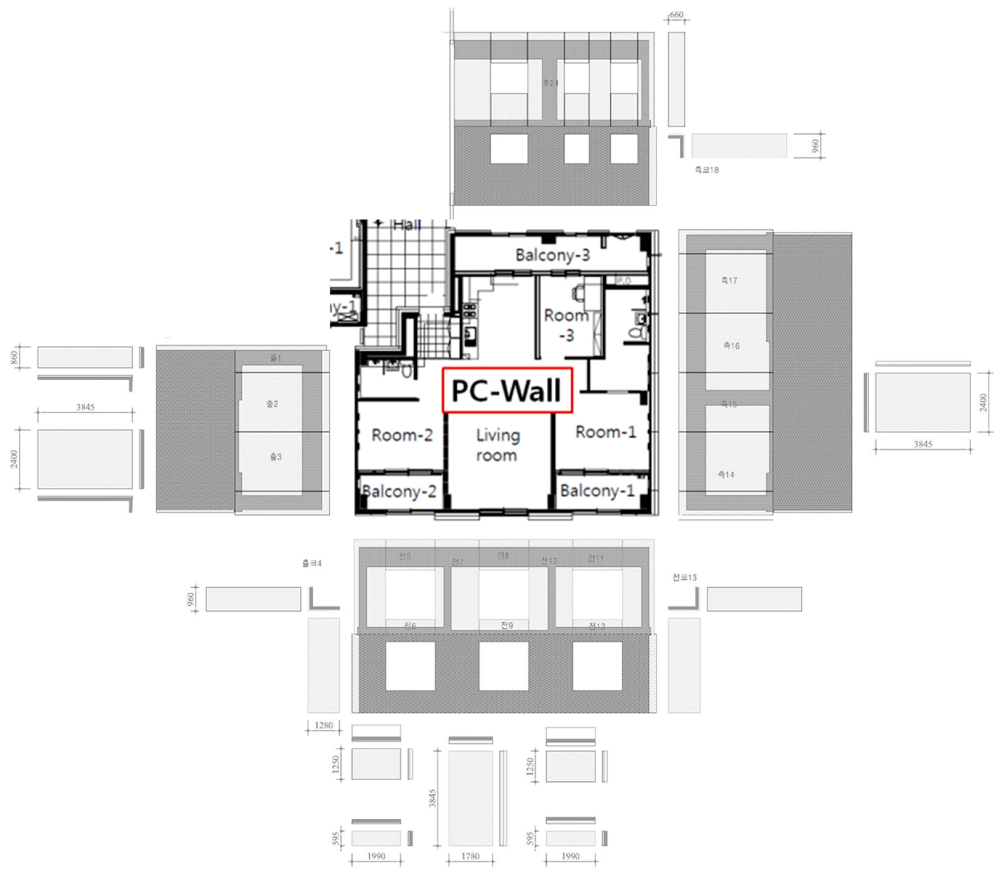
The application area of the external insulation PC-Wall is designed as 84 m2 of one generation in the apartment with a total of 29 members as shown in Figure 9.
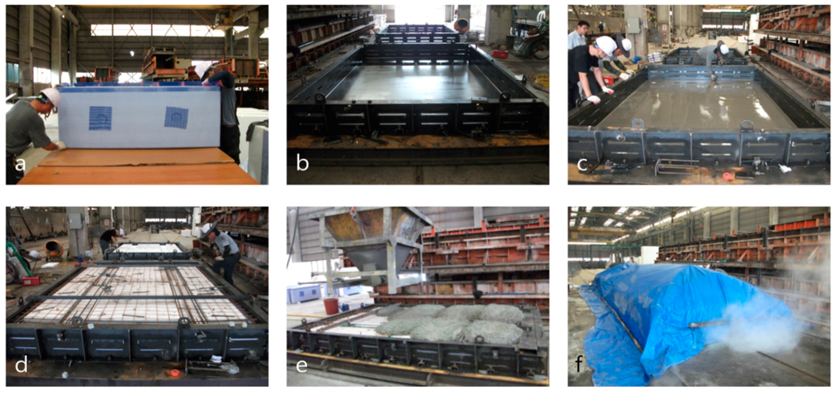
A total of 29 members were produced at the PC factory as shown in Figure 10 for its application on-site.
As a result of performing manufacturing work off-site on a factory, the quality for each piece of panel was secured. Two molds were used to produce 29 pieces, of which two pieces were able to be fabricated per day. In case of installing additional molds for invigorating manufacturing process in terms of speed, mass production of the PC-wall will be possible in future.
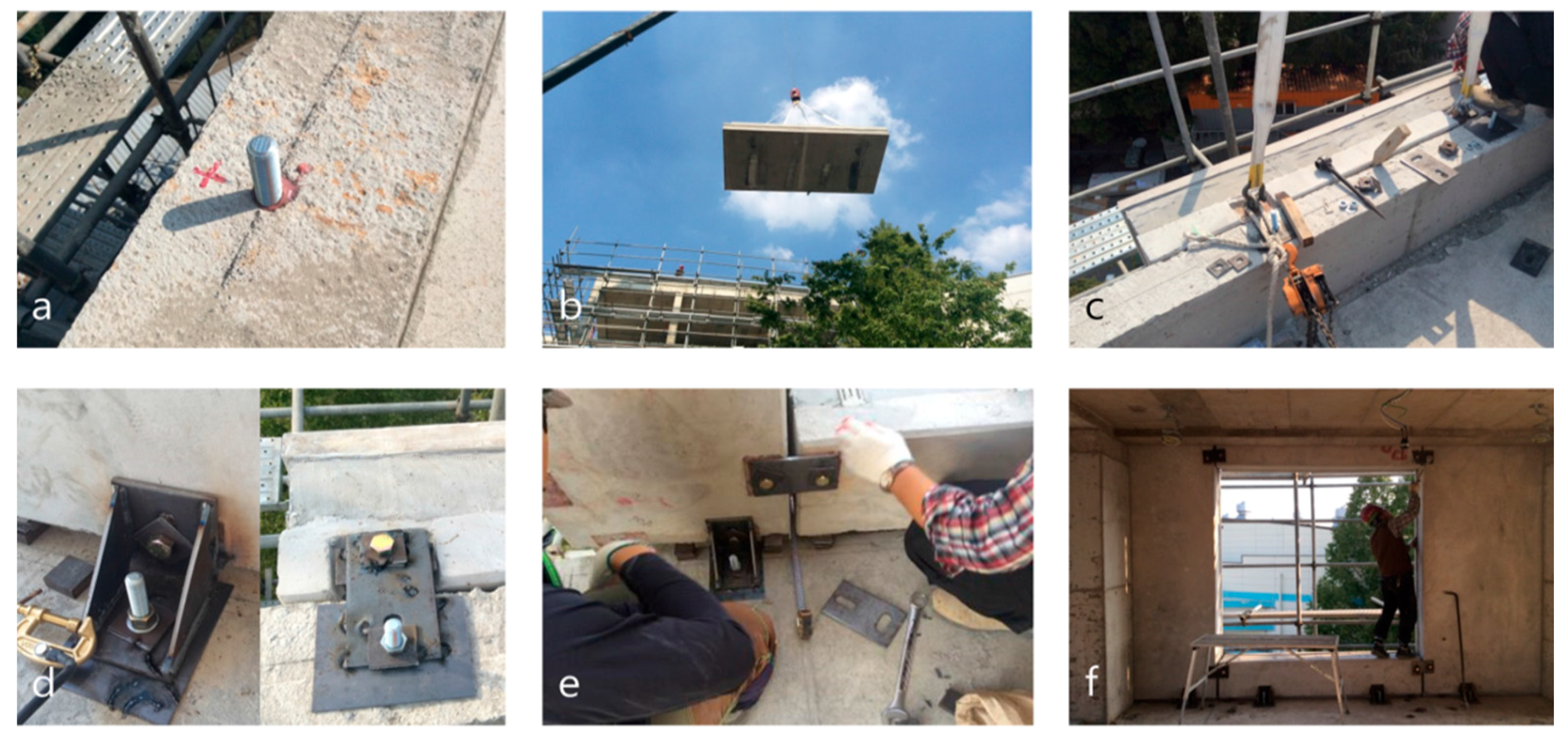
All members transported from the factory to the site were lifted to their installation positions using a crane. After locating each member, fasteners were applied to fix the members. All sequences for construction work on-site are shown in Figure 11.
The installation time per member was about 40 min (as of six people for each member). It is considered that minimizing the number of members in the design of members is advantageous for improving the workability.
4.2. Productivity Analysis
As a predictive model for forecasting productivity in case of applying the insulation method proposed throughout this study in future, productivity of the external insulated PC-Wall when applied to actual field was analyzed using CYCLONE simulation technique. CYCLONE is a management tool for measuring productivity by applying logical interrelationships between resources, work hours and work types [43,44,45]. The simulation tool represents a network constituting information of circulated work. Since CYCLONE is an efficient technique to predict the productivity and the construction period of a project based on construction type [46,47,48], productivity of the developed method and the productivity of the existing external insulation wet construction are compared using the corresponding management tools, thereby verifying and the applicability of the developed PC-Wall method.
Prior to utilizing CYCLONE for evaluating productivity per hour, the size of construction works or project to be evaluated (work time, input equipment, work crew composition, etc.) and the start and completion times of the simulation should be similar. In addition, the number of times the work is measured and the total amount of resources inputted should be comparable on field for data input. What this study conducted was a comparative evaluation of productivity of a newly developed system with that of an existing construction method of which some minor works can change according to the characteristics of construction projects without any definite, standardized work process. An external insulation wet construction can change the order of detailed works and either increase or decrease the number of works depending on the type of construction (residential, non-residential buildings) or size (construction cost) and the number of input labor and equipment (gondola or tower crane input) can be changed. Therefore, in this study, the following research procedure was established to compare the productivity of the external insulation wet method with the productivity of the external insulated PC-Wall.
In preparation of test-bed, the construction work process of the external insulation PC-Wall was analyzed and the actual working time and resources were measured and recorded 15 times total. CYCLONE model was developed and simulation was implemented in the future. For comparative analysis with existing external insulation wet construction, case study and expert consultation on 10 different cases of external insulation wet construction similar to the scale of external insulation PC-Wall and established the wet construction work process as shown in Table 8. CYCLONE simulation was implemented by correcting the input and output values using the data of the construction cases.
In addition, sensitivity analysis was conducted to derive optimum resource allocation combination of construction equipment and labor during construction using the developed model.
4.2.1. Construction Processes of External Insulated PC-Wall System
In order to collect the data to be reflected in the CYCLONE model, work processes of PC-Wall were divided into pre-assembly (prior to on-site fabrication), assembly (on-site fabrication) and post-assembly (post-on-site fabrication) and then analyzed as shown in Table 9 below.
While construct the CYCLONE model, the field manager interviews and field measurements were used to identify the information on pre- and post- relationships, work time and work group composition. The actual working time and the number of input resources were secured for each type of work via use of stopwatch and movie shooting at the field observation. The field measurements were performed 15 times in total and the measured time for each type of work was recorded for each trial. After listing all 15 data on total duration for each work process, (1) minimum duration lapsed, (2) maximum duration lapsed and (3) most frequently lapsed duration were noted separately. The reason for summarizing and classifying the work time into three categories such as “minimum”, “most likely” and “maximum” is to implement the simulation under the triangular distribution for performing productivity analysis and deriving the most probable and approximate results.
The raw data on durations of each classified work process that were collected on field was seemingly under a high deviation, with the gaps between the maximum and minimum durations being high. All data on recorded working time and the number of input resources was thus demonstrated to other field experts for verifying the probability and reliability of the results. There has been a minor adjustment on raw data and then the final data has been set as depicted on Table 9.
4.2.2. Simulation Model
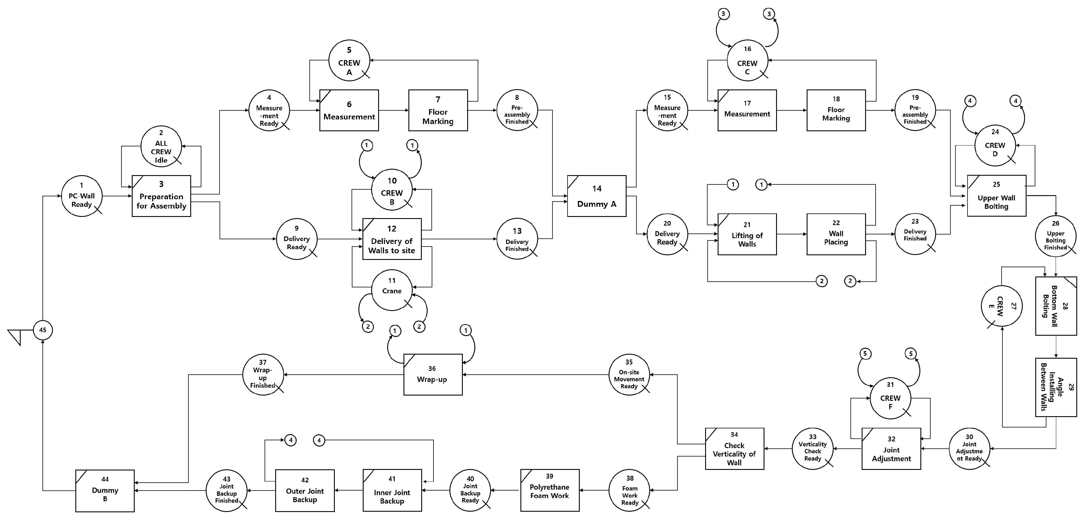
The CYCLONE model was constructed using the work process of the re-entrained PC-Wall construction and the analysis of the time data of the element work (Figure 12). The work process for one floor of the external insulation PC-Wall construction can be classified as follows.
• Prior to on-site fabrication (Nodes 1~14 of Figure 12)
Prior to on-site assembly of the adiabatic PC-Wall, the operators simultaneously perform field measurements, feedings and in-situ wall member entry. When crew A performs measurement and floor marking operations in series, crew B gets ready to lift the members by the crane after taking the members into the forklift. Operations of crew A and crew B are expressed in parallel on the CYCLONE model to demonstrate simultaneity of work processes.
• On-site fabrication (Nodes 15~37 of Figure 12)
In the assembly work between the PC-Wall for external insulation, the workers complete the positioning of the wall by lifting the wall member with the crane and aligning the members. Then, the operators on que bolt the upper and lower portions of the wall and performs the angle assembly between the wall members when the upper and lower bolting are completed. After the angle is assembled, the joints between the wall members are adjusted and the wall verticality check is completed. After the completion of the wall assembly, crew B that carried all prefabricated members into the site, cleans the site. In this study, the simulation model is implemented by considering the cleaning work as the production work.
• Post-on-site fabrication (Nodes 38~44 of Figure 12)
After the assembly work is completed, the crews must complete the finishing work by carrying out backup and corking work on the inner and outer joints of the wall. Wall joint finishing was regarded as the process of external insulated PC-Wall construction.
4.2.3. Productivity Analysis of the System
Productivity analysis on the newly proposed insulation system was performed based on input resources and work time for each type of work. Productivity based on the CYCLONE simulation can represent how many cycles the simulation of the target construction can be performed per unit time (minutes).
According to the productivity analysis results, the hourly productivity of the developed PC Wall system was measured as 0.0305. Also, the total duration of 100 simulations was 3278 h, which insinuates that the total time required for one cycle was 32.78 h.
Table 10 shows the results of comparing the productivity of the conventional external insulation wet method and the external insulated PC-Wall method. It has been verified that in case of applying the external insulated PC-Wall method and the previously activated external insulation wet method under the same condition, the cycle execution time of the external insulation PC-Wall construction is 32.78 h and the productivity is 0.0305. Meanwhile, productivity of the conventional wet method turned out to be 0.0272, with the execution time being 36.75 h per cycle. In other words, in terms of productivity, the external wall PC-Wall method is superior to the conventional wet method.
4.2.4. Sensitivity Analysis
A sensitivity analysis of the productivity based on the changes of the resource combination such as the equipment and the working tank put into the external insulation PC-Wall construction was evaluated in this study. In case of extensively applying the newly proposed wall system on actual site, decision-makers such as construction managers should decide the combination of resources that can contribute to an effective, efficient and most economical construction depending on the site conditions.
The original conditions of the input value for productivity analysis are as follows—one set of crane, two workers for preparation work (Crew A), two workers to carry and lift the wall members to the site and also perform other supplementary work (Crew B), three workers to perform the frame work (Crew C), two workers mainly for upper bolting work (Crew D), three workers for bolting the lower part of the wall (Crew E), five workers to perform joint adjustment and verticality check between the walls (Crew F) and two workers to arrange the site after the main work (Crew B again). In pursuant for analyzing the optimal combination of resources for the maximum productivity of the external insulation PC construction, resource ranges have been set as follows for a sensitivity analysis module—from one to two tower cranes, two to four workers on Crew A, two to four on Crew B, three to five workers on Crew C, two to four workers on Crew D, three to five workers on Crew E and five to seven workers Crew F.
As a result of the sensitivity analysis, the highest productivity value was 0.0876 among the productivity showed by resource variation (Table 11). This means that the combination of resources with the highest productivity value in the range of resource variation of this study is the optimal combination. In other words, two tower cranes, four workers on Crew A, four workers on Crew B, four workers on Crew C, four workers on Crew D, five workers on Crew E and seven workers on Crew F yielded the maximum productivity during the simulation of applying the newly proposed External Insulated PC-Wall system on site.
5. Conclusions
Even though external insulation method has been spotlighted as a construction method that can sustain the building energy, the method has not been actively applied for various reasons. Thus, a high-performance composite external insulated Precast Concrete (PC) wall system was developed and proposed as a probable solution to the strengthening energy performance standards that are emphasized worldwide. Throughout this study, effectiveness and efficiency of the proposed method have been verified through performance evaluation, applicability test and productivity analysis.
The conclusion of this study is as follows:
(1) The PC-Wall with integrated wall, insulation and finishing materials ensures passive house-level insulation performance, it is an eco-friendly construction method that has excellent insulation performance of 40% or more and light weight of 50% compared to existing wall by designing thin plate (50 mm) of PC wall.
(2) A pre-construction mock-up test was carried out by making a specimen of actual size to evaluate the basic performance of PC-Wall. The basic performance was evaluated as airtight performance, watertight performance, structural performance, residual deformation and relative story displacement test. It is considered that the developed wall can be practically applied due to its verification of safety from wind load and seismic load.
(3) The applicability of the external insulated PC-Wall was evaluated by performing a test bed for actual apartment house application. As a result of the evaluation, it was confirmed that quality could be secured by pre-fabricated production and one piece per mold could be produced per day. It is confirmed that the installation time per member is about 40 min (based on 6 persons in construction) and it is considered that minimizing the number of members in member design is advantageous for improving the workability.
(4) Sensitivity analysis was performed using CYCLONE technique to derive the maximum resource allocation combination of equipment and manpower along with productivity analysis based on the process analysis results of PC-Wall. As a result, the productivity per hour of the developed method was measured as 0.0305, which yields a higher value than that of the conventionally applied EIFS that was measured as 0.0272. Results of the sensitivity analysis, which insinuate the optimum allocation of resources for an effective, efficient and economical construction work, can also contribute for active utilization of the developed method on site.
Author Contributions
Ho Baik, Minju Kim, Sang-Heon Lee and Hunhee Cho conceived and designed the experiments; Ho Baik and Sang-Heon Lee performed the experiments; Ho Baik and Minju Kim analyzed the data; Hunhee Cho contributed reagents/materials/analysis tools; Ho Baik, Minju Kim, Sang-Heon Lee and Hunhee Cho wrote the paper.
Conflicts of Interest
The authors declare no conflict of interest.
References
- Mohsen, M.S.; Akash, B.A. Some prospects of energy savings in buildings. Energy Convers. Manag. 2001, 42, 1307–1315. [Google Scholar] [CrossRef]
- Pekdogan, T.; Basaran, T. Thermal performance of different exterior wall structures based on wall orientation. Appl. Therm. Eng. 2017, 112, 15–24. [Google Scholar] [CrossRef]
- Song, S.; Koo, B.; Lim, J. Comparison of Annual Heating and Cooling Energy Demands of Internally and Externally Insulated Apartment Buildings Considering the Thermal Bridging Effect and the Heat Capacity Difference Using Monthly Calculation Method of ISO 13790. J. Archit. Inst. Korea 2007, 26, 321–332. [Google Scholar]
- Aditya, L.; Mahlia, T.; Rismanchi, B.; Ng, H.; Hasan, M.; Metselaar, H.; Muraza, O.; Aditiya, H. A review on insulation materials for energy conservation in buildings. Renew. Sustain. Energy Rev. 2017, 73, 1352–1365. [Google Scholar] [CrossRef]
- Anastaselos, D.; Giama, E.; Papadopoulos, A.M. An assessment tool for the energy, economic and environmental evaluation of thermal insulation solutions. Energy Build. 2009, 41, 1165–1171. [Google Scholar] [CrossRef]
- Ueno, K. Residential Exterior Wall Superinsulation Retrofit Details and Analysis. Building Science Corporation, Research Report. 2012. Available online: web.orni.gov/sci/buildings/conf-archive/2010%20B11%20papers/200_Ueno.pdf (accessed on 9 November 2017).
- Schiavoni, S.; D’alessandro, F.; Bianchi, F.; Asdrubali, F. Insulation materials for the building sector: A review and comparative analysis. Renew. Sustain. Energy Rev. 2016, 62, 988–1011. [Google Scholar] [CrossRef]
- Künzel, H.M. Effect of interior and exterior insulation on the hygrothermal behaviour of exposed walls. Mater. Struct. 1998, 31, 99–103. [Google Scholar] [CrossRef]
- Kolaitis, D.I.; Malliotakis, E.; Kontogeorgos, D.A.; Mandilaras, I.; Katsourinis, D.I.; Founti, M.A. Comparative assessment of internal and external thermal insulation systems for energy efficient retrofitting of residential buildings. Energy Build. 2013, 64, 123–131. [Google Scholar] [CrossRef]
- Tettey, U.Y.A.; Dodoo, A.; Gustavsson, L. Effects of different insulation materials on primary energy and CO2 emission of a multi-storey residential building. Energy Build. 2014, 82, 369–377. [Google Scholar] [CrossRef]
- Sulakatko, V.; Lill, I.; Liisma, E. Analysis of On-site Construction Processes for Effective External Thermal Insulation Composite System (ETICS). Procedia Econ. Financ. 2015, 21, 297–305. [Google Scholar] [CrossRef]
- Kub, E.G.; Cartwright, L.G.; Oppenheim, I.J. Cracking in Exterior Insulation and Finish Systems. J. Perform. Constr. Facil. 1993, 7, 60–66. [Google Scholar] [CrossRef]
- Lampo, R.; Trovillion, J.C. Evaluation of Test Methods to Determine the Impact Resistance of Exterior Insulation and Finish Systems (EIFS); US Army Corps of Engineers, Construction Engineering Research Laboratory: Champaign, IL, USA, 1992. [Google Scholar]
- Rodríguez-Soria, B.; Domínguez-Hernández, J.; Pérez-Bella, J.M.; Coz-Díaz, J.J.D. Review of international regulations governing the thermal insulation requirements of residential buildings and the harmonization of envelope energy loss. Renew. Sustain. Energy Rev. 2014, 34, 78–90. [Google Scholar] [CrossRef]
- Enforcement Decree of the Building Act. Presidential Decree No. 27365. Available online: extwprlegs1.fao.org/docs/pdf/kor168153.pdf (accessed on 6 July 2017).
- Pargana, N.; Pinheiro, M.D.; Silvestre, J.D.; Brito, J.D. Comparative environmental life cycle assessment of thermal insulation materials of buildings. Energy Build. 2014, 82, 466–481. [Google Scholar] [CrossRef]
- Bomberg, M.; Kumaran, K.; Day, K. Moisture Management of EIFS Walls—Part 1: The Basis for Evaluation. J. Therm. Envel. Build. Sci. 1999, 23, 78–94. [Google Scholar]
- Mazor, M.H.; Mutton, J.D.; Russell, D.A.M.; Keoleian, G.A. Life Cycle Greenhouse Gas Emissions Reduction from Rigid Thermal Insulation Use in Buildings. J. Ind. Ecol. 2011, 15, 284–299. [Google Scholar] [CrossRef]
- Castro, E.B.P.D.; Mequignon, M.; Adolphe, L.; Koptschitz, P. Impact of the lifespan of different external walls of buildings on greenhouse gas emissions under tropical climate conditions. Energy Build. 2014, 76, 228–237. [Google Scholar] [CrossRef]
- Coma, J.C.A.; Pérez, G.; Solé, C.; Castell, A.; Cabeza, L.F. New Green Facades as Passive Systems for Energy Savings on Buildings. Energy Procedia 2014, 57, 1851–1859. [Google Scholar] [CrossRef]
- Garay, R.; Arregi, B.; Elguezabal, P. Experimental Thermal Performance Assessment of a Prefabricated External Insulation System for Building Retrofitting. Procedia Environ. Sci. 2017, 38, 155–161. [Google Scholar] [CrossRef]
- Bojan, A.; Aciu, C. Optimal Technologies for External Thermal Insulation with Polystyrene Panels for Different Support Materials. Procedia Technol. 2015, 19, 512–517. [Google Scholar] [CrossRef]
- Al-Sanea, S.A.; Zedan, M.F. Effect of insulation location on thermal performance of building walls under steady periodic conditions. Int. J. Ambient Energy 2001, 22, 59–72. [Google Scholar] [CrossRef]
- Imbabi, M.S.-E. A passive–active dynamic insulation system for all climates. Int. J. Sustain. Built Environ. 2012, 1, 247–258. [Google Scholar] [CrossRef] [Green Version]
- Ozel, M. Effect of insulation location on dynamic heat-transfer characteristics of building external walls and optimization of insulation thickness. Energy Build. 2014, 72, 288–295. [Google Scholar] [CrossRef]
- Han, C. An Experimental Study for Evaluations of Mock-Up Tests of ALC Panels in Exterior Wall of Buildings. Master’s Thesis, Wonkwang University, Iksan, Korea, 2013. [Google Scholar]
- Einea, A. Strucutral and Thermal Efficiency of Precast Concrete Sandwich Panel Systems. Ph.D. Thesis, The University of Nebraska, Lincoln, NE, USA, January 1992. [Google Scholar]
- Yu, J.; Yang, C.; Tian, L. Low-energy envelope design of residential building in hot summer and cold winter zone in China. Energy Build. 2008, 40, 15–24. [Google Scholar] [CrossRef]
- Alkhawaja, M. Determination and selecting the optimum thickness of insulation for buildings in hot countries by accounting for solar radiation. Appl. Therm. Eng. 2004, 24, 2601–2610. [Google Scholar] [CrossRef]
- Nyers, J.; Kajtar, L.; Tomić, S.; Nyers, A. Investment-savings method for energy-economic optimization of external wall thermal insulation thickness. Energy Build. 2015, 86, 268–274. [Google Scholar] [CrossRef]
- Vilhena, A.C.B.; Silva, C.; Fonseca, P.; Couto, S. Exterior walls covering system to improve thermal performance and increase service life of walls in rehabilitation interventions. Constr. Build. Mater. 2017, 142, 354–362. [Google Scholar] [CrossRef]
- Stazi, F.; Vegliò, A.; Perna, C.D.; Munafò, P. Experimental comparison between 3 different traditional wall constructions and dynamic simulations to identify optimal thermal insulation strategies. Energy Build. 2013, 60, 429–441. [Google Scholar] [CrossRef]
- Çomaklı, K.; Yüksel, B. Optimum insulation thickness of external walls for energy saving. Appl. Therm. Eng. 2003, 23, 473–479. [Google Scholar] [CrossRef]
- Wang, Y.; Huang, Z.; Heng, L. Cost-effectiveness assessment of insulated exterior walls of residential buildings in cold climate. Int. J. Proj. Manag. 2007, 25, 143–149. [Google Scholar] [CrossRef]
- Voellinger, T.; Bassi, A.; Heitel, M. Facilitating the incorporation of VIP into precast concrete sandwich panels. Energy Build. 2014, 85, 666–671. [Google Scholar] [CrossRef]
- Amran, Y.M.; Rashid, R.S.; Hejazi, F.; Safiee, N.A.; Ali, A.A. Response of precast foamed concrete sandwich panels to flexural loading. J. Build. Eng. 2016, 7, 143–158. [Google Scholar] [CrossRef]
- Gombeda, M.J.; Trasborg, P.; Naito, C.J.; Quiel, S.E. Simplified model for partially-composite precast concrete insulated wall panels subjected to lateral loading. Eng. Struct. 2017, 138, 367–380. [Google Scholar] [CrossRef]
- Choi, H.-K.; Choi, Y.-C.; Choi, C.-S. Development and testing of precast concrete beam-to-column connections. Eng. Struct. 2013, 56, 1820–1835. [Google Scholar] [CrossRef]
- Dong, Y.H.; Jaillon, L.; Chu, P.; Poon, C. Comparing carbon emissions of precast and cast-in-situ construction methods—A case study of high-rise private building. Constr. Build. Mater. 2015, 99, 39–53. [Google Scholar] [CrossRef]
- AAMA 501.1-05 Standard Test Method for Water Penetration of Windows, Curtain Walls and Doors Using Dynamic Pressure. 2005. Available online: https://aamanet.org/ (accessed on 20 January 2017).
- AAMA 501.4-09 Recommended Static Testing Method for Evaluating Curtain Wall and Storefront Systems Subjected to Seismic and Wind Induced Interstory Drift. 2015. Available online: https://aamanet.org/ (accessed on 20 January 2017).
- ASTM E283-04 Standard Test Method for Determining Rate of Air Leakage through Exterior Windows, Curtain Walls and Doors under Specified Pressure Differences Across the Specimen. 2012. Available online: https://www.astm.org/Standards (accessed on 20 January 2017).
- Sawhney, A.; Abourizk, S.M.; Halpin, D.W. Construction project simulation using CYCLONE. Can. J. Civ. Eng. 1998, 25, 16–25. [Google Scholar] [CrossRef]
- Huang, R.-Y.; Chen, J.-J.; Sun, K.-S. Planning gang formwork operations for building construction using simulations. Autom. Constr. 2004, 13, 765–779. [Google Scholar] [CrossRef]
- Packer, E. A Literature Review of Simulation of Construction Operations. Master’s Dissertation, Brigham Young University, Provo, UT, USA, 2002. [Google Scholar]
- Jeong, J.; Hong, T.; Ji, C.; Kim, J.; Lee, M.; Jeong, K.; Lee, S. An integrated evaluation of productivity, cost and CO2 emission between prefabricated and conventional columns. J. Clean. Prod. 2017, 142, 2393–2406. [Google Scholar] [CrossRef]
- Hong, T.; Cho, K.; Hyun, C.; Han, S. Simulation-Based Schedule Estimation Model for ACS-Based Core Wall Construction of High-Rise Building. J. Constr. Eng. Manag. 2011, 137, 393–402. [Google Scholar] [CrossRef]
- Lee, D.-E.; Yi, C.-Y.; Lim, T.-K.; Arditi, D. Integrated Simulation System for Construction Operation and Project Scheduling. J. Comput. Civ. Eng. 2010, 24, 557–569. [Google Scholar] [CrossRef]
Figure 1.
System of insulation: (a) Internal insulation; (b) Sandwich panel; (c) External insulation.
Figure 1.
System of insulation: (a) Internal insulation; (b) Sandwich panel; (c) External insulation.

Figure 2.
Conceptual diagram of external insulation PC-Wall.

Figure 3.
Section of external insulation PC-Wall.

Figure 4.
Detail of slab and external insulation PC-Wall.

Figure 5.
Joint detail between external insulation PC-Walls.

Figure 6.
Structural performance test.

Figure 7.
Test procedures on interlayer drift.

Figure 8.
Results of second relative story displacement test: (a) Fastener damage; (b) Horizontal joint damage.
Figure 8.
Results of second relative story displacement test: (a) Fastener damage; (b) Horizontal joint damage.

Figure 9.
PC-Wall members of test-bed.

Figure 10.
Manufacture Process of PC-Wall. (a) Preparation of insulation; (b) Installation of mold; (c) Application of finishing mortar; (d) Installs of insulation and reinforcing bar; (e) Placement of concrete; (f) Steam curing.
Figure 10.
Manufacture Process of PC-Wall. (a) Preparation of insulation; (b) Installation of mold; (c) Application of finishing mortar; (d) Installs of insulation and reinforcing bar; (e) Placement of concrete; (f) Steam curing.

Figure 11.
Construction Process of PC-Wall. (a) Perforation and insertion of anchors; (b) Pulling up by crane; (c) Locating the placement position; (d) Fixation by bolting; (e) Assembly of an angle steel; (f) Finishing of joint.
Figure 11.
Construction Process of PC-Wall. (a) Perforation and insertion of anchors; (b) Pulling up by crane; (c) Locating the placement position; (d) Fixation by bolting; (e) Assembly of an angle steel; (f) Finishing of joint.

Figure 12.
CYCLONE Model of External Insulated PC-Wall.


Table 1.
Comparison of internal and external insulation methods.
| Division | U-Value | Weight (kg/m2) | Thickness (mm) | |||
|---|---|---|---|---|---|---|
| Material | Thickness (m) | Thermal Conductivity (W/m·K) | Resistance of Heat Transmission (m2·K/W) | |||
| Internal insulation (Existed RC-Wall) | External surface thermal resistance | - | - | 0.043 | 360 | Concrete 200 Insulation 150 |
| EPS Insulation | 0.3 | 0.036 | 4.567 | |||
| Concrete | 0.2 | 1.6 | 0.152 | |||
| Gypsum board | 0.01 | 0.18 | 0.053 | |||
| Inner surface thermal resistance | - | - | 0.11 | |||
| Total resistance of Heat transmission (m2·K/W) | - | - | 4.925 | |||
| U-value (W/m2·K) | - | - | 0.2 | |||
| External insulation (PC-Wall) | External surface thermal resistance | - | - | 0.043 | 190 | Concrete 50 Insulation 300 Self-Leveling 5 |
| Self-leveling mortar | 0.005 | 1.4 | 0.004 | |||
| EPS Insulation | 0.3 | 0.036 | 8.451 | |||
| Concrete | 0.05 | 1.6 | 0.031 | |||
| Gypsum board | 0.01 | 0.18 | 0.053 | |||
| Inner surface thermal resistance | - | - | 0.11 | |||
| Total resistance of heat transmission (m2·K/W) | - | - | 8.691 | |||
| U-value (W/m2·K) | - | - | 0.115 | |||
Table 2.
Result of air tightness test.
| Division | Measured Value | Allowable Value |
|---|---|---|
| Air leakage | 0.005 CFM/ft2 | 0.06 CFM/ft2 |
Table 3.
Result of water tightness test.
| Division | Positive Pressure | Dynamic Pressure |
|---|---|---|
| Water leakage | No leakage | No leakage |
Table 4.
Results of structural performance test.
| Division | Allowable Value | Measured Value | |
|---|---|---|---|
| Positive Pressure | Negative Pressure | ||
| Height deflection (mm) | 6.96 | 0.42 | 1.08 |
| Width deflection (mm) | 6.19 | 0.02 | 0.21 |
Table 5.
Results of residual deformation test.
| Division | Allowable Value | Measured Value | |
|---|---|---|---|
| Positive Pressure | Negative Pressure | ||
| Height deformation (mm) | 5.01 | 0.02 | 0.02 |
| Width deformation (mm) | 4.46 | 0.08 | 0.10 |
Table 6.
Results of interlayer drift test.
| Division | Test #1 | Test #2 |
|---|---|---|
| Deflection | L/400 (7.0 mm) | L/100 (28.0 mm) |
| Allowable value | Keep on function and form of all walls | |
| Results | No deflection | Horizontal joint and Fastener damages |
| Allowable buildings | High Occupancy Assembly Standard Occupancy Essential Facility | High Occupancy Assembly Standard Occupancy |
Table 7.
Summary of Test-bed.
| Location | Ilsan, Gyeonggi-do, Korea (In Korea Institute of Civil engineering and building Technology) | 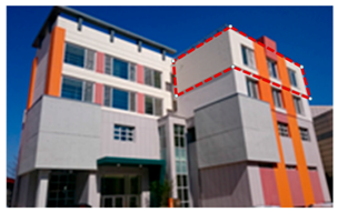 |
| Purpose for Facilities | Facilities for Education and Research | |
| Usage of Each Story | Public Information (1F), Monitoring Room (2F), Experiment lab (3F) Experiment lab (4F) | |
| PC-Wall Part | 4F 1 household (84 m2, 29 walls) |
Table 8.
Process analysis of PC-Wall.
| Classification | Work Process | |
|---|---|---|
| Preparation Work | 1 | Preparation for Assembly |
| Preparation Work | 2 | Protection Work around Window Openings |
| Preparation Work | 3 | Surface Treatment with P-Primer |
| Preparation Work | 4 | Delivery of Materials to the Site |
| Insulation Board Attachment | 5 | Admixture of Adhesive and Cement |
| Insulation Board Attachment | 6 | Back-wrapping Mesh |
| Insulation Board Attachment | 7 | Insulation Board Attachment |
| Mesh | 8 | Fastener Drill |
| Mesh | 9 | Detailed Back-wrapping |
| Mesh | 10 | Mesh Work |
| Finishing Work | 11 | Primer Work |
| Finishing Work | 12 | Finishing Work |
| Finishing Work | 13 | Joint Sealant Insertion |
| Finishing Work | 14 | Clean-up |
Table 9.
Process analysis of PC-Wall.
| Classification | Work Process | Duration (min) | Resource | |||
|---|---|---|---|---|---|---|
| Min. | Most Likely | Max. | ||||
| Pre-Assembly | 1 | Preparation for Assembly | 18 | 30 | 58 | All Crew |
| Pre-Assembly | 2 | Actual Measurement | 50 | 58 | 70 | Crew A |
| Pre-Assembly | 3 | Floor Marking | 48 | 58 | 68 | Crew A |
| Pre-Assembly | 4 | Delivery of PC-Walls to the Site | 75 | 87 | 102 | Crew B, T/C |
| Assembly | 4 | Delivery of PC-Walls to the Site | 75 | 87 | 102 | Crew B, T/C |
| Assembly | 5 | Punching Chemical-anchor Hole on the RC Slab | 150 | 174 | 188 | Crew C |
| Assembly | 6 | Installing Chemical-anchor on the RC Slab | 108 | 116 | 120 | Crew C |
| Assembly | 7 | Lifting PC-Wall | 130 | 145 | 155 | Crew B, T/C |
| Assembly | 8 | Placing Exact Location | 273 | 290 | 316 | Crew B |
| Assembly | 9 | Bolting Upper PC-Wall | 129 | 145 | 150 | Crew D |
| Assembly | 10 | Bolting Bottom PC-Wall | 134 | 145 | 166 | Crew E and D |
| Assembly | 11 | Installing Angle between PC-Walls | 130 | 145 | 147 | Crew E and D |
| Assembly | 12 | Adjusting joint of PC-Walls and Check Vertical Degree | 485 | 580 | 644 | Crew F |
| Assembly | 13 | Field Clean-up | 4 | 5 | 5.5 | Crew F and B |
| Assembly | 14 | Inner Joint Backup/Sealant | 115 | 142 | 152 | Crew D |
| Post-Assembly | 14 | Inner Joint Backup/Sealant | 115 | 142 | 152 | Crew D |
| Post-Assembly | 15 | Outer Joint Backup/Sealant | 110 | 145 | 150 | Crew D |
| After Assembly | 16 | Field Clean-up | 24 | 30 | 35 | Crew B |
Table 10.
Productivity analysis of PC-Wall construction.
| Productivity Information | |||
|---|---|---|---|
| Method | Total Simulation Time (h) | Cycle Number | Productivity (Cycle/h) |
| Ext. Insulated PC-Wall | 3278.1 | 100 | 0.0305059 |
| Conventional EIFS | 3675.6 | 100 | 0.0272065 |
Table 11.
Sensitivity analysis of PC-Wall construction.
| Crane | Crew A | Crew B | Crew C | Crew D | Crew E | Crew F | Productivity |
|---|---|---|---|---|---|---|---|
| 1 | 2 | 2 | 3 | 3 | 4 | 5 | 0.0722 |
| 1 | 2 | 3 | 5 | 2 | 4 | 7 | 0.0734 |
| 1 | 3 | 4 | 3 | 2 | 3 | 5 | 0.0780 |
| 1 | 4 | 4 | 3 | 3 | 3 | 5 | 0.0791 |
| 1 | 4 | 4 | 4 | 2 | 5 | 7 | 0.0800 |
| 2 | 4 | 4 | 4 | 4 | 3 | 7 | 0.0833 |
| 2 | 4 | 4 | 4 | 4 | 5 | 7 | 0.0876 |
| 2 | 4 | 4 | 5 | 3 | 5 | 7 | 0.0850 |
| 2 | 4 | 4 | 5 | 4 | 4 | 7 | 0.0836 |
| 2 | 4 | 4 | 5 | 4 | 5 | 7 | 0.0861 |
© 2018 by the authors. Licensee MDPI, Basel, Switzerland. This article is an open access article distributed under the terms and conditions of the Creative Commons Attribution (CC BY) license (http://creativecommons.org/licenses/by/4.0/).
Share and Cite
MDPI and ACS Style
Baik, H.; Kim, M.; Lee, S.-H.; Cho, H. Simulation Model for Productivity Analysis of External Insulated Precast Concrete Wall System. Sustainability 2018, 10, 105. https://doi.org/10.3390/su10010105
AMA Style
Baik H, Kim M, Lee S-H, Cho H. Simulation Model for Productivity Analysis of External Insulated Precast Concrete Wall System. Sustainability. 2018; 10(1):105. https://doi.org/10.3390/su10010105
Chicago/Turabian StyleBaik, Ho, Minju Kim, Sang-Heon Lee, and Hunhee Cho. 2018. "Simulation Model for Productivity Analysis of External Insulated Precast Concrete Wall System" Sustainability 10, no. 1: 105. https://doi.org/10.3390/su10010105
Note that from the first issue of 2016, this journal uses article numbers instead of page numbers. See further details here.