An Admission Control Mechanism for 5G LWA


Department of Information and Communication Engineering, Yeungnam University, Gyeongsan si 38541, Korea
*
Author to whom correspondence should be addressed.
Sustainability 2018, 10(6), 1999; https://doi.org/10.3390/su10061999
Submission received: 23 May 2018
/
Revised: 11 June 2018
/
Accepted: 12 June 2018
/
Published: 13 June 2018
(This article belongs to the Special Issue 5G Mobile Services and Scenarios: Challenges and Solutions)
Abstract
:To alleviate the spectrum scarcity problem in fifth-generation (5G) networks, traditional mobile data offloading schemes from long term evolution (LTE) to wireless local area networks (WLANs) have been revised by the third-generation partnership project (3GPP) in release 13, which is known as LTE-WLAN aggregation (LWA). With LWA, user equipment units (UEs) supporting both LTE and WLAN can utilize both LTE and WLAN links simultaneously. Thus, UEs under the coverage of an LWA network will be surrounded by multiple standards, such as LTE, WLAN, and LWA, along with cells of different sizes and coverage. Providing the LWA service to all UEs unconditionally may lead to serious intra-cell unfairness, degradation of system-level quality of service (QoS), and a reduction in system resource utilization. Hence, to resolve this issue, two important challenges need to be addressed: Which LTE UEs should be transferred, and how many LTE UEs need to be transferred. In this paper, we propose a user-offloading algorithm for evolved node B (eNB) hardware that smartly allocates the deprived LTE UEs and assigns the LWA service to an optimal number of UEs without degrading the QoS for existing WLAN UEs. With this proposed scheme, all LWA-preferred UEs with poor LTE performance and a good WLAN condition have the opportunity to access LWA service to improve performance. We show that the proposed scheme maximizes the throughput performance of the whole network.
1. Introduction
The unprecedented escalation in demand for more capacity in cellular networks [1] has imposed significant challenges due to the limited licensed spectrum [2]. Any effort to achieve capacity growth through network densification faces the challenge of severe inter-cell interference. The solution to this issue is to make the best use of all spectrum types through matured technology. Therefore, the free and abundant amount of underutilized spectrum below the 6 GHz band motivates operators to combine long term evolution (LTE) with wireless local area network (WLAN) technology in fifth-generation (5G) networks [3,4,5]. LTE-WLAN aggregation at the link layer, popularly known as LWA [6], is considered to be one of the latest groundbreaking innovations with the third generation partnership project (3GPP) release 13, providing high performance and a better user experience under a unified network. Motivated by the existence of a significant number of WLAN access points (APs) and indoor coverage deployed by a mobile network operator (MNO), LWA takes advantage of better usage of both WLAN and LTE access technology, eliminating their individual challenges. A WLAN benefits from large downlink bandwidth, but suffers from inefficient uplink bandwidth caused by contention, whereas LTE benefits from efficient scheduling on uplink but suffers from bandwidth scarcity on downlink. Hence, LWA redirects uplink traffic from WLAN to LTE and avoids resource waste due to WLAN contention on uplink. Since a radio channel is fully under the control of the scheduler (i.e., downlink is controlled by the WLAN AP, and uplink is controlled by the LTE scheduler), delays and rates can be guaranteed. The LWA radio protocol architecture supports two kinds of data bearers: Split and switched bearers. As the names suggest, packets belonging to a switched LWA bearer are always scheduled over a WLAN by evolved node B (eNB), whereas packets belonging to a split LWA bearer can be scheduled over either a WLAN or LTE. In both cases, the packets received through both interfaces are reordered at the link layer and delivered to the higher layer in order.
At present, the majority of traffic offloading studies, such as licensed assisted access (LAA) [7], LTE in the unlicensed band (LTE-U) [8], and LWA, focus on the use of unlicensed spectrum to leverage an overloaded LTE network with its free and abundant bands. However, the unlicensed bands below 6 GHz are already crowded by WLAN user equipment units (UEs) [9]. When other coexisting technologies along with LWA come into action, it will be more congested [10,11]. For incumbent WLAN UEs, the network will be highly congested and will waste most of its time in contending for the channel. On the other hand, LWA UEs face high latency due to bottlenecks at WLAN APs. Eventually, these conditions lead to performance degradation for both standards, hurting system-level quality of service (QoS). Therefore, LWA should wisely consider steering the UEs’ traffic, scrutinizing network loads, and improving WLAN utilization when it is available and not congested. Moreover, LWA should contribute to increasing the intra-cellular fairness between UEs. This means that the LWA opportunities must be given to UEs that make the best use of it (i.e., proportional fairness). Inspired by the above challenges with LWA, we present a framework of mode selection for LWA-preferred UEs, taking into account the QoS of both WLAN and LTE UEs. Our proposed algorithm smartly assigns LWA service to needy UEs, and guarantees an enhanced user experience for LWA UEs without degrading the QoS of existing WLAN UEs. Additionally, this algorithm contributes to maximizing network throughput and performance.
The rest of the paper is organized as follows. In Section 2, the related work on LWA is presented along with the main contributions of our work. In Section 3, the system model is described, and the problem formulated. LWA admission control algorithms are also presented. Numerical results are provided in Section 4, and finally, Section 5 concludes the paper.
2. Related Work
An extensive array of research effort exists in the academic and industrial domains over cellular operators utilizing the unlicensed band [12] owing to free and abundant bands. Most of the effort on opportunistically using WLAN APs for delay-tolerant applications has been done in WLAN offloading [13]. To provide unified LTE/WLAN access, there are three main levels of integration between the two technologies: Loose integration, tight integration, and very tight integration. In loose integration [14], WLAN and LTE networks are physically independent, but they are connected to the same internet protocol (IP) network. Some of the examples of loose integration proposed by 3GPP release 8 are the access network discovery and selection function (ANDSF) [15] and radio access network (RAN)-assisted/controlled LTE WLAN radio interworking (RALWI/RCLWI) [6] [16]. In the tight integration standardized by the 3GPP in release 10 [17], WLAN APs are directly connected to the LTE evolved packet core network. However, UEs still need to use WLAN security mechanisms, which are time consuming. Recently, in releases 12 and 13, the 3GPP standardized very tight integration [18] in order to overcome the inefficiency that existed in Release 10. That includes LAA [7], LTE-WLAN radio level integration with IPsec tunnel (LWIP) [6], and LWA [6]. Here, WLAN APs under the coverage of LTE eNB are connected to the eNB. The data traffic is offloaded to the WLAN, while the control functions (such as security and mobility) are kept in the LTE network. The main difference between LTE-U/LAA and LWIP/LWA is that LAA uses LTE radio access technology to operate in the unlicensed spectrum, while LWIP and LWA access it through IEEE 802.11 standards, thus allowing them to use the incumbent WLAN deployments. Other remarkable examples to aggregate LTE and WLANs, rather than opportunistically using one of them, include multipath transmission control protocol (MPTCP) at the transport layer by the internet engineering task force (IETF) [19]. MPTCP provides a method of joining independent TCP sub-streams to provide a reliable connection between client and server applications, but it lacks provision of intra-cell fairness between UEs [20]. Table 1 shows the differences between the four main technologies proposed for tighter integration in 5G.
Regarding LWA, there has not been much research. However, some of the studies relate to TCP delay minimization [21] and traffic steering [22]. Some papers worked on maximizing LWA network throughput based on mathematical optimization [23], which is NP hard, in general. Additionally, most of the research only considered increasing LTE throughput, but failed to consider the ability of AP terminals to aggregate LWA traffic [24]. The AP’s capability to hold LWA service is a very important factor for alleviating congestion and enhancing performance under both standards. Therefore, inspired by the above work, the contributions of our paper are as follows.
- We propose an algorithm to activate the optimal number of LWA UEs, accounting for the accommodating capacity of the WLAN network, as well as guaranteeing QoS for LWA UEs.
- We prove with numerical results that our proposed algorithm achieves better system throughput gain, compared with a random mechanism and an LTE-W mechanism.
- The complexity of our proposed algorithm holds to only O(QM2) for worst-case time complexity, whereas eNB can hold Q APs, comprised of M UEs, and MlogM is the complexity in sorting.
- We present a detailed procedure for LWA activation and deactivation.
3. System Model
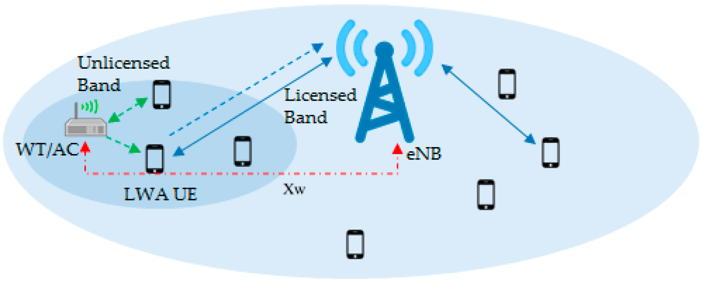
We consider a scenario with eNB and APs, enabling many UEs to fall under the coverage of both LTE and WLAN APs, as shown in Figure 1. An eNB is connected to the MNO-operated Q APs, usually called wireless terminal (WT)/access controllers (ACs), by a high-speed backhaul link, which is common practice in the present day. M UEs equipped with both LTE and WLAN transceivers (smartphones) and another set of N UEs supported with WLAN-only transceivers (laptops/tablets) are uniformly distributed under the coverage of both LTE and a WLAN network. As mentioned in TS Report 36.300 [6], the eNB holds all the necessary statistics of all MNO-operated APs and UEs under the APs in its database. The M UEs under the coverage of both standards will have three options: option 1, WLAN-only; option 2, LTE-only; and option 3, LWA. Options 1 and 2 are the default connections available on the market. Option 3 will be added for LWA service. Moreover, each UE is restricted from using more than one communications mode. Whenever the LTE UEs’ attachments are modified to accommodate option 3, they will be reported to the eNB. Note that we consider a case where, even if UEs choose option 3 mode, there is no guarantee they will be served by LWA. However, they will be listed as LWA-preferred UEs in the eNB hardware, and later approved in the eNB by our proposed algorithm. Following 3GPP release 13, LWA supports downlink transmission for WLANs and both uplink and downlink transmission for LTE.
3.1. Problem Formulation
For the cellular network, downlink transmission is based on orthogonal frequency-division multiple access (OFDMA), which enables a base station (BS) to transmit to multiple UEs simultaneously. The system throughput models for LTE UEs can be enhanced through spectrum efficiency. The spectrum efficiency of UE m without mutual interference in LTE networks, Cm, can be written as
where Bm is the bandwidth allocated to UE m, Pm is the transmission power allocated on the licensed band for UE m, Hm is the channel power gain between transmitter and receiver m, and N0 is the noise power. Hence, achievable throughput Rl from the LTE network can be formulated as
When multiple UEs are connected through WLAN networks, the UEs have to compete for the unlicensed channel opportunities by using the carrier sensing mechanism popularly known as the distributed coordination function (DCF) protocol. With DCF, the system throughput of the WLAN network is related to the number of competing WLAN UEs. Let Ptr be the probability that there is at least one transmission signal in a time slot, and let Ps be the probability that there is no collision on a channel. Then, they can be expressed as
where τ is the transmission probability for each of the UEs, and N is the number of competing WLAN UEs. According to Bianchi [25], the throughput of the WLAN network, Rw, can be expressed as
where Ts is the average time that the channel is sensed as busy caused by a successful transmission, Tc is the average time that the channel is sensed as busy by each station during a collision, E[P] is the average packet size, and Tσ is the duration of an empty time slot.
In LWA access mode, the selected LTE UE traffic will be transmitted through the unlicensed band over an MNO-operated AP network. Therefore, with LWA activation, there will be an additional m UEs in a WLAN AP to the N WLAN UEs already being served in the WLAN network. For this condition, throughput for each of the LWA UEs or WLAN UEs can be expressed by Rw(N + m)/(N + m), where Rw(N + m) is the system throughput of the WLAN network with an additional m LWA UEs from the cellular network defined in (5).
3.2. Challenges on an Unlicensed Band
The WLAN is the most popular and successful technique for providing wireless services on unlicensed bands. With the low costs and high date rates, WLAN systems have already been a dominant player in all unlicensed bands at 2.4 GHz and 5 GHz. However, due to the limited spectrum, WLAN network operators are feeling the crunch in providing service in crowded areas such as public buildings, universities, hotels, hospital, restaurants, stadiums, etc. A lot of research has been done to improve WLAN capacity [26,27]. In this situation, if LWA directs LTE traffic to WLAN networks, the unlicensed bands will be more congested. This will result in degradation of network performance in both networks. Hence, proper measurement to handle congestion and interference across different networks should be introduced to optimize system performance. In order to facilitate this, two important challenges need to be addressed; they are as follows.
Challenge 1: How many LTE UEs need to be transferred to LWA?
It seems that an LTE network will obtain the maximum benefit when it transfers the maximum number of its UEs for LWA activation. However, this is not always true. A WLAN AP works on an unlicensed band that is highly unreliable. As LWA technology uses unlicensed bands for downlink, the delay led by out-of-order packets and multiple retransmissions may be intolerable, compared to an LTE system. Additionally, the active WLAN-only UEs in the AP can add additional delays in accessing the channel. If the difference between the delays in packet delivery in LWA and LTE is too large, the throughput will be worse when using both interfaces than if using a single interface. Therefore, eNB hardware needs to be very careful in transferring LTE UEs for LWA activation and should guarantee a minimum rate for LWA UEs. Moreover, the operation of LWA should not affect ongoing transmissions of WLAN-only UEs.
Challenge 2: Which LTE UEs should be transferred?
In order to maximize total system throughput, the opportunity for LWA activation must be given to the UEs that make the best use of it. Intuitively, the assignment of LWA service is very beneficial for the system if an LWA opportunity is given to the UEs getting lower throughput from LTE networks. However, that is not always the best case. Since, we are offloading LTE traffic to a WLAN, the traffic conditions and signal quality of the WLAN network play an important role. Let us consider a situation where the LTE users are getting low throughput from LTE. Those UEs might be connected with either a heavily loaded WLAN AP or a distant WLAN AP with very low signal strength. In this situation, it is a bad idea to offload the LTE UEs to a WLAN AP where throughput is lower than the LTE network. Hence, consideration of both network conditions is imperative for performance improvement. The UEs with the lowest LTE instantaneous throughput and highest throughput from a WLAN work best for LWA activation.
3.3. The Proposed LWA Algorithm
We consider the LWA architecture shown in Figure 2 using radio resource management (RRM), for which details were provided by Lin et al. [28]. The RRM entity in eNB is responsible for admitting or rejecting new UE requests for practicing LWA procedure. RRM functionalities can be divided into four different parts, i.e., database, interface, cell control, and UE control. The RRM database stores UE records such as current state, bearer configurations, ongoing procedure, LWA related configuration information from Aps, and WLAN measurement reports. The interface entity allows interaction between radio resource control (RRC) and mobility management entity (MME) layers. The cell control helps to control cellular configurations for interference and broadcasting messages. The UE control section controls UE admission. In this UE control section, the LWA entity has been introduced to handle the WLAN measurement reports and to control the downlink data path by executing LWA activation, deactivation, and mobility. There is a load balancing (LB) entity which mitigates uneven distribution of the traffic load over LTE and WLAN. Similarly, the radio admission control (RAC) entity interacts with the RRM (responsible for LTE and WLAN radio resource management) to decide whether new radio bearers should be established according to available resources in LTE/WLAN and their QoS requirements. The radio bearer control (RBC) establishes the data radio bearers (DRBs) based on their radio bearer configurations after they are admitted by the RAC. Our algorithm resides on the LB entity which executes whenever a new bearer is created by RAC and distributes the data through the LTE and WLAN by modifying radio bearers at the RBC entity. There is an additional connection mobility control (CMC) entity which helps for mobility management and handover between the APs.
The proposed LWA activation algorithm is summarized in Algorithm 1 and is described as follows. The APs are operated by the same cellular network providers. All the APs’ parameters, as well as their connected UEs’ information, are accessible to the eNB through backhaul networks, such as optical links. In the RRM database, UEs under each LWA-supported WLAN AP are listed with their LTE and WLAN throughputs. Among those UEs, LWA-preferred UEs are listed with normalized throughput gain. The normalized throughput gain is the achievable throughput gain in the network when the UEs’ data are offloaded to the WLAN via LWA activation.
| Algorithm 1. The proposed algorithm for optimum allocation of LWA UEs. |
 |
Likewise, in order to find needy LTE UEs that can maximize network performance under both standards, UEs are sorted in decreasing order of achievable throughput gain. By doing this, LTE UEs that suffer from the lowest throughput and have the capacity to gain the highest throughput under LWA will be selected first from the list for LWA activation. This makes the most of system throughput performance, as well as UEs’ throughput in both networks.
Furthermore, the maximum number of LTE UEs, mmax, that the LTE network can admit, can be calculated by
where is the throughput threshold of LWA UEs. This equation guarantees the LTE UEs (mmax) with the minimum throughput of in the unlicensed band. This threshold can be dynamically set by eNB based on the type of data and the network conditions.
To consider the total system throughput gain from the LWA network, we define the throughput gain function from WLAN and LTE network perspectives. Throughput gain in a WLAN network is due to the additional LWA UEs accessing the WLAN network. Similarly, in an LTE network, it is due to offloaded LWA UEs relinquishing bandwidth for the remaining LTE UEs. We define function f(n) as follows:
where Gi is the throughput gain for the remaining LTE UEs. The LWA system achieves its maximum gain when it transfers the optimal number of UEs from the LTE network to the WLAN network with guaranteed per user minimum throughput of in WLAN. Thus, the optimal number of UEs, l, that maximize throughput gain can be formulated as
n = 0, 1, 2, 3….mmax.
In this way, overall system throughput can be maximized without degrading WLAN throughput. From this algorithm, MNO-operated APs select the optimal number of UEs to be served by LWA, guaranteeing the minimum throughput for LWA UEs without degrading WLAN system throughput.
3.4. LWA Activation and Deactivation Procedures
When UEs initiate LWA service requests by selecting option 3 (i.e., LWA mode), the eNB requires UEs to perform WLAN measurement in order to receive information on WLAN radio conditions (i.e., a WLAN connection status report). The UEs perform WLAN measurement to detect the status of the connected WLAN AP. The WLAN measurement report is comprised of the received signal strength indicator (RSSI), the WLAN identifier, WLAN carrier information, channel utilization, a station count, the admission capacity, the WLAN rate, the backhaul rate, and information about UEs connected to the WLAN. Based on the WLAN measurement report (a RRC report) on the RRM database, the eNB executes the UEs’ selection algorithm residing on a LB entity for LWA activation or deactivation by configuring the bearer at the RRM layer. The detailed algorithm run by eNB is shown in Figure 3. The procedure is divided into six major parts, which are (a) user capability inquiry, (b) eNB configuration of WLAN measurements, (c) measurement configuration/report, (d) eNB informs the WT about user capability, (e) LWA activation, and (f) feedback/flow control.
3.4.1. For LWA Activation
- The RRM entity of the eNB gets the packet data convergence protocol (PDCP) layer to configure the bearer of the UEs to the WLAN. Configurations of bearers can be of two types: a switch or a split bearer.
- Switch bearer: Since only one data path is possible, the RRM suggests PDCP for switching the bearer configuration from LTE to WLAN only.
- Split bearer: The LB entity commands execution of split scheduling at the PDCP layer that strips the incoming packets (PDCP protocol data units [PDUs]) of the LWA UE bearer into two links. However, the data transmission ratio between the links can be variable based on the traffic condition and load of the WLAN network, which is outside the scope of this article.
- Before a PDU is transmitted by the WLAN interfaces, the LWA adaptation protocol (LWAAP) entity processes the data and generates an LWAAP PDU containing a DRB identity (DRBID) (a one-byte header to each PDCP PDU). Furthermore, Ether Type 0X9E65 is added by the WLAN AP for forwarding LWA data packets to UEs over the WLAN. Later on, this information is used by UEs to identify the LWA bearer of the receiving PDU.
- After reception of data by UEs, the UEs differentiate the LWA packets from normal packets by processing them through the LWAAP entity, where the LWAAP header is removed, and then forwards the packets to the PDCP instance based on the DRBID. In return, an LWA status report is sent via LTE to the eNB to acknowledge correct reception of the LWA packets.
- The LWA status report constitutes the first missing sequence number (FMS), the highest received sequence number on the WLAN (HRW), and the number of missing PDUs (NMP).
- Based on LWA status feedback through UEs, the eNB maintains traffic through the WLAN for LWA UEs.
3.4.2. For LWA Deactivation
- 5.
- The RRM entity of the eNB requires the PDCP layer to use the default bearer configuration, which is LTE for UEs.
- 6.
- PDUs will be sent through an LTE-only path to UEs.
4. Numerical Results
In this section, we present simulation results to validate the performance of the introduced LWA admission control algorithm in terms of system throughput. We use Matlab simulator in order to assess the network performance. The performance evaluation was conducted in an enterprise scenario of 200 m × 200 m, where there is an LTE small cell eNB located at the center and a WLAN AP within it. The LTE and WLAN UEs are distributed uniformly within the coverage area of the LTE network and WLAN network, respectively. We adopted the IEEE 802.11ax protocol with Request to Send/Clear to Send (RTS/CTS) access mechanism on 5 GHz in the simulations. Most simulation assumptions follow the 3GPP recommendations. A detailed description of the simulation parameters is given in Table 2. In the simulation, we considered the conventional LTE-only and WLAN-only technology as benchmark technology (without LWA), with system throughput representing the aggregated downlink throughput of LTE and WLAN networks. We also compared our results with random transfer and LTE-W [20]. A number of the random LTE UEs were selected for LWA activation in a random transfer. UEs were selected for activation of LWA service on LTE-W based on the lowest LTE throughput.
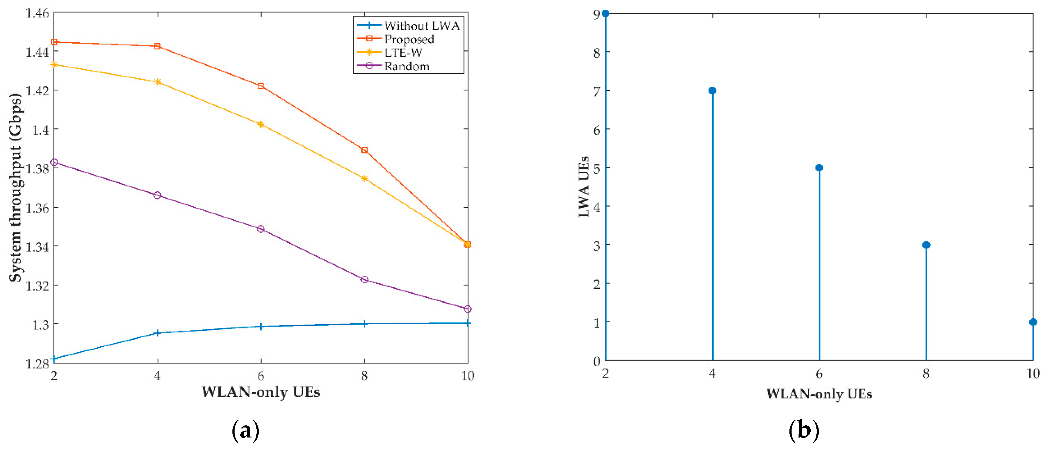
Figure 4a shows the system throughput for a variable number of WLAN-only UEs. We considered a scenario where the LTE network is crowded with LTE UEs, while the WLAN network is uncrowded. In this scenario, if we increase the number of WLAN-only UEs, we can see an increase in system throughput for the benchmark technology. This gain is contributed by the increase in utilization of the uncrowded WLAN system. However, this gain decreases as the number of WLAN UEs increases towards the saturation point of the system, as shown in Figure 4a. In the same figure, with LWA technologies, we considered offloading some of the LTE users to the WLAN. As discussed earlier in Section 3.3, the throughput gain in an LWA network constitutes the gain from the WLAN and LTE networks. The gain from the WLAN network is mainly due to utilization of the underloaded WLAN AP, whereas for the LTE network, it is from the remaining LTE UEs occupying more resources after offloading to the WLAN network. In other words, the per-user data rate of the remaining LTE users increases after offloading. However, as WLAN UEs increase, our algorithm limits the number of LTE users being offloaded to the WLAN, as shown in Figure 4b. Consequently, the system throughput gain achieved in both the WLAN and LTE networks decreases significantly. As a result, a decreasing trend in the overall throughput of the LWA network is observed.
Figure 5 shows that the system throughput decreases as the number of LTE UEs increases. As discussed earlier, our algorithm limits the amount of LWA offloading based on the accepting capacity of the WLAN network. Hence, increasing LTE users above the WLAN capacity will cause a further increase in resource sharing among LTE users, i.e., the per-user data rate decreases.
This results in a decrease in throughput gain from the LTE network, and thus, the overall system throughput is reduced. For the benchmark technology, as the number of LTE UEs increases, the central scheduler will efficiently distribute the traffic among all UEs (i.e., the per-user data rate decreases, but more users with lower rates can transmit at the same time) to maintain higher system throughput in the network.
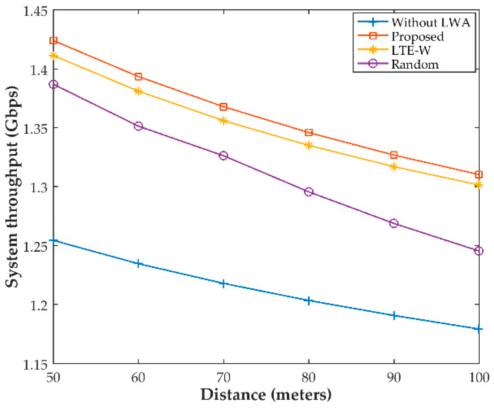
Figure 6 shows decreases in the system throughput as the distance between the eNB and the AP increases for constant number of LTE and WLAN UES (20 and 1 respectively). The reason for this result is that signal loss and error will be more pronounced in WLAN signals as the distance increases. In addition, more resources will be required to support the same number of UEs.
From all the figures, it is noted that our proposed algorithm always achieves better system throughput than the random method and the LTE-W method. This signifies the importance and advantage of selecting needy UEs from the perspectives of both LTE and the WLAN. Therefore, all the results demonstrate that our proposed algorithm contributes to maximizing network throughput and performance by optimally assigning LWA service to poor UEs without degrading the QoS of the existing WLAN UEs.
5. Conclusions
In this paper, we proposed an LWA admission control mechanism for eNBs, which finds the optimum number of LTE UEs for LWA activation. To facilitate this, two important challenges are addressed: which LTE UEs should be transferred, and how many LTE UEs need to be transferred. Through numerical simulations, we proved that our proposed algorithm contributes to maximizing network throughput and performance by optimally assigning LWA service to poor UEs without degrading the QoS of existing WLAN UEs.
Author Contributions
Conceptualization and methodology, R.B.; simulation and writing, R.B. and R.S.; supervision, S.W.K.
Acknowledgments
This work was supported by the 2018 Yeungnam University Research Grant.
Conflicts of Interest
The authors declare no conflicts of interest.
References
- CS Inc. Cisco Visual Networking Index: Forecast and Methodology, 2016–2021. 6 June 2017. Available online: https://www.cisco.com/ (accessed on 20 January 2017).
- Bajracharya, R.; Shrestha, R.; Zikria, Y.B.; Kim, S.W. LTE in the unlicensed spectrum: A survey. IETE Tech. Rev. 2018, 35, 78–90. [Google Scholar] [CrossRef]
- Ling, J.; Kanugovi, S.; Vasudevan, S.; Pramod, A.K. Enhanced capacity and coverage by Wi-Fi LTE integration. IEEE Commun. Mag. 2015, 53, 165–171. [Google Scholar] [CrossRef] [Green Version]
- Al-Dulaimi, A.; Al-Rubaye, S.; Ni, Q.; Sousa, E. 5G communications race: Pursuit of more capacity triggers LTE in unlicensed band. IEEE Veh. Technol. Mag. 2015, 10, 43–51. [Google Scholar] [CrossRef]
- Chatzikokolakis, K.; Spapis, P.; Kaloxylos, A.; Alonistioti, N. Toward spectrum sharing: Opportunities and technical enablers. IEEE Commun. Mag. 2015, 53, 26–33. [Google Scholar] [CrossRef]
- 3GPP TS 36.300. Evolved Universal Terrestrial Radio Access (E-UTRA) and Evolved Universal Terrestrial Radio Access Network (E-UTRAN); Overall Description; Stage 2, V.13.3.0; 3GPP: Sophia Antipolis, France, 2016.
- 3GPP Standard TR 36.889. Feasibility Study on Licensed-Assisted Access to Unlicensed Spectrum; 3GPP: Sophia Antipolis, France, 2015.
- Qualcomm. Extending the Benefits of LTE Advanced to Unlicensed Spectrum; Qualcomm White Paper; Qualcomm: San Diego, CA, USA, 2014. [Google Scholar]
- Cracking the Crowded 2.4 GHz Conundrum. 22 July 2016. Available online: https://www.ingenu.com/2016/07/cracking-the-crowded-2-4ghz-conundrum/ (accessed on 6 February 2017).
- Bhorkar, A.; Ibars, C.; Zong, P. On the throughput analysis of LTE and WiFi in unlicensed band. In Proceedings of the 2014 48th Asilomar Conference on Signals, Systems and Computers, Pacific Grove, CA, USA, 2–5 November 2014. [Google Scholar]
- Nihtila, T.; Tykhomyrov, V.; Alanen, O.; Uusitalo, M.A.; Sorri, A.; Moisio, M.; Iraji, S.; Rastuk, R.; Mangalvedhe, N. System performance of LTE and IEEE 802.11 coexisting on a shared frequency band. In Proceedings of the 2013 IEEE Wireless Communications and Networking Conference, Shanghai, China, 7–10 April 2013. [Google Scholar]
- Cui, H.; Leung, V.C.M.; Li, S.; Wang, X. LTE in the Unlicensed Band: Overview, Challenges, and Opportunities. IEEE Wirel. Commun. 2017, 24, 99–105. [Google Scholar] [CrossRef]
- Tight, Tighter and Very Tight Integration between LTE and WiFi Networks. Available online: https://smallcells.3g4g.co.uk/2014/07/tight-tighter-and-very-tight.html (accessed on 9 March 2017).
- Buddhikot, M.M.; Chandranmenon, G.; Han, S.; Lee, Y.-W.; Miller, S.; Salgarelli, L. Design and implementation of a wlan/cdma2000 interworking architecture. IEEE Commun. Mag. 2003, 41, 90–100. [Google Scholar] [CrossRef]
- 3GPP TS 24.312 v.12.10.0, Access Network Discovery and Selection Function (ANDSF) Management Object (MO); 3GPP: Sophia Antipolis, France, September 2015.
- 3GPP TS 23.234, Universal Mobile Telecommunications System (UMTS); LTE; 3GPP System to Wireless Local Area Network (WLAN) Interworking; System Description; V.13.1.0; 3GPP: Sophia Antipolis, France, 2017.
- 3GPP TS 23.402. Architecture Enhancements for Non-3GPP Accesses; Release 10, Technical Specification, Technical Report; 3GPP: Sophia Antipolis, France, 2012.
- Lagrange, X. Very tight coupling between lte and wifi for advanced offloading procedures. In Proceedings of the 2014 IEEE Wireless Communications and Networking Conference Workshop, Istanbul, Turkey, 6–9 April 2014. [Google Scholar]
- Ford, A.; Raiciu, C.; Handley, M.; Bonaventure, O. TCP Extensions for Multipath Operation with Multiple Addresses; RFC 6824; Internet Engineering Task Force (IETF): Fremont, CA, USA, 2013. [Google Scholar]
- Jin, B.; Kim, S.; Yun, D.; Lee, H.; Kim, W.; Yi, Y. Aggregating LTE and Wi-Fi: Toward Intra-Cell Fairness and High TCP Performance. IEEE Trans. Wirel. Commun. 2017, 16, 6295–6308. [Google Scholar] [CrossRef]
- López-Pérez, D.; Laselva, D.; Wallmeier, E.; Purovesi, P.; Lundén, P.; Virtej, E.; Lechowicz, P.; Malkamaki, E.; Ding, M. Long Term Evolution-Wireless Local Area Network Aggregation Flow Control. IEEE Access 2016, 4, 9860–9869. [Google Scholar] [CrossRef]
- Zhang, N.; Zhang, S.; Wu, S.; Ren, J.; Mark, J.W.; Shen, X. Beyond Coexistence: Traffic Steering in LTE Networks with Unlicensed Bands. IEEE Wirel. Commun. 2016, 23, 40–46. [Google Scholar] [CrossRef]
- Liu, B.; Zhu, Q.; Zhu, H. Delay-Aware LTE WLAN Aggregation for 5G Unlicensed Spectrum Usage. In Proceedings of the 2017 IEEE 85th Vehicular Technology Conference, Sydney, Australia, 4–7 June 2017. [Google Scholar]
- Chen, Q.; Yu, G.; Maaref, A.; Li, G.Y.; Huang, A. Rethinking Mobile Data Offloading for LTE in Unlicensed Spectrum. IEEE Trans. Wirel. Commun. 2016, 15, 4987–5000. [Google Scholar] [CrossRef]
- Bianchi, G. Performance Analysis of the IEEE 802.11 Distributed Coordination Function. IEEE J. Sel. Area Commun. 2000, 18, 535–547. [Google Scholar] [CrossRef]
- Wang, T.; Yang, Q.; Tan, K.; Zhang, J.; Liew, S.C.; Zhang, S. DCAP: Improving the Capacity of WiFi Networks with Distributed Cooperative Access Points. IEEE Trans. Mob. Comput. 2018, 17, 320–333. [Google Scholar] [CrossRef]
- Jamil, I.; Cariou, L.; Helard, J.F. Improving the capacity of future IEEE 802.11 high efficiency WLANs. In Proceedings of the 2014 21st International Conference on Telecommunications (ICT), Lisbon, Portugal, 4–7 May 2014. [Google Scholar]
- Lin, Y.B.; Shih, Y.J.; Chao, P.W. Design and Implementation of LTE RRM with Switched LWA Policies. IEEE Trans. Veh. Technol. 2018, 67, 1053–1062. [Google Scholar] [CrossRef]
Figure 1.
System model of LTE and WLAN coexistence.

Figure 2.
Functional block diagram of LWA system.

Figure 3.
An overview of the LWA procedure.

Figure 4.
(a) System throughput with variable numbers of WLAN-only UEs; and (b) the number of LTE UEs transferred with variable numbers of WLAN-only UEs.
Figure 4.
(a) System throughput with variable numbers of WLAN-only UEs; and (b) the number of LTE UEs transferred with variable numbers of WLAN-only UEs.

Figure 5.
System throughput with variable number of LTE UEs.

Figure 6.
System throughput with variable distance.


Table 1.
Comparison of alternative technologies in 5G.
| Components | LTE-U/LAA | LWA | LWIP | MPTCP |
|---|---|---|---|---|
| Complete name | LTE in unlicensed/License Assisted Access | LTE WLAN Aggregation | LTE WLAN Integration with IP Tunneling | Multipath TCP |
| WLAN relation | Coexistence | Aggregation | Aggregation | Aggregation |
| RAT * |  |  |  |  |
| Standardization | LTE-U forum/3GPP | 3GPP | 3GPP | IETF |
| Leading work group (WG) | RAN WG1 | RAN WG2 | RAN WG2 | MPTCP WG1 |
| Release | Release 12/Release 13 | Release 13 | Release 13 | RFC6824, etc. |
| Protocol layer | Link layer (MAC layer) | Link layer (PDCP) | IP layer (IP tunnel) | Network layer (MPTCP) |
| New device function | UE and eNB (5 GHz LTE) | PDCP | IPsec | MPTCP |
| Network element | LTE-U/LAA small cell | LWA eNB, WT | LWA eNBs, LWIP-SeGW | MPTCP Proxy |
| Performance gain | High | High | Medium | High |
| Traffic direction | Downlink | Downlink | Uplink + Downlink | Uplink + Downlink |
| Deployment eNB/AP | Collocated | Collocated/Non-collocated | Non-collocated | Non-collocated |
| Access network cost | High (new LTE small cell with LTE-U/LAA @ 5 GHz) | Medium (new small cell: LWA aware WLAN terminal) | None (uses existing WLAN AP) | None (uses existing WLAN AP) |
* Blue: LTE Band, Green: Unlicensed band, Character: MAC/PHY, Space: non-collocated.
Table 2.
Simulation parameters.
| Parameters | Values |
|---|---|
| BS and AP distance | 50~100 m |
| Downlink bandwidth | 20 MHz |
| Noise power | −174 dBm |
| Path loss for cellular links | 15.3 + 37.6log10(d)m |
| Path loss for unlicensed band | 15.3 + 50log10(d)m |
| Transmission power of eNB | 36 dBm |
| Transmission power of AP | 24 dBm |
| Number of WLAN UEs | 2~10 |
| Number of LTE UEs | 20~40 |
| E[P] | 1500 bytes |
| CWmin | 16 |
| CWmax | 1024 |
| WLAN bit rate | 1 Gbps |
| PHY Header | 192 bits |
| MAC Header | 224 bits |
| Delay | 20 μs |
| SIFS | 16 μs |
| DIFS | 50 μs |
| Slot time | 9 μs |
| ACK | 112 bits + PHY header |
| RTS | 160 bits + PHY header |
| CTS | 112 bits + PHY header |
© 2018 by the authors. Licensee MDPI, Basel, Switzerland. This article is an open access article distributed under the terms and conditions of the Creative Commons Attribution (CC BY) license (http://creativecommons.org/licenses/by/4.0/).
Share and Cite
MDPI and ACS Style
Bajracharya, R.; Shrestha, R.; Kim, S.W. An Admission Control Mechanism for 5G LWA. Sustainability 2018, 10, 1999. https://doi.org/10.3390/su10061999
AMA Style
Bajracharya R, Shrestha R, Kim SW. An Admission Control Mechanism for 5G LWA. Sustainability. 2018; 10(6):1999. https://doi.org/10.3390/su10061999
Chicago/Turabian StyleBajracharya, Rojeena, Rakesh Shrestha, and Sung Won Kim. 2018. "An Admission Control Mechanism for 5G LWA" Sustainability 10, no. 6: 1999. https://doi.org/10.3390/su10061999
Note that from the first issue of 2016, this journal uses article numbers instead of page numbers. See further details here.