Model of Power System Stabilizer Adapting to Multi-Operating Conditions of Local Power Grid and Parameter Tuning

1
State Grid Hebei Electric Power Co., Ltd., Technology Research Institute, Shijiazhuang 050021, China
2
School of Electrical Engineering, Wuhan University, Wuhan 430072, China
*
Author to whom correspondence should be addressed.
Sustainability 2018, 10(6), 2089; https://doi.org/10.3390/su10062089
Submission received: 15 May 2018
/
Revised: 28 May 2018
/
Accepted: 29 May 2018
/
Published: 20 June 2018
(This article belongs to the Special Issue Wave Energy Technologies: A Sustainable Energy Source)
Abstract
:The rapid development of the modern power grid has resulted in significant changes to the dynamic characteristics of regional power grids. Moreover, the operating conditions of power grids are increasingly complex, and uncertainty factors are on the rise, which makes it difficult for a conventional power system stabilizer (PSS) to provide enough damping for the power system. To solve the problem where the conventional model and parameter-tuning method of a PSS cannot adapt to the multi-operating conditions of the modern power system, a new emergency control model of PSS (E-PSS) that can adapt to the multi-operating conditions of the local power grid and a method of parameter tuning based on probabilistic eigenvalue are proposed in this paper. An emergency control channel is also installed on the PSS2B. The conventional channel is used to control the system under normal operating conditions, which ensures that the system meets the conditions of dynamic stability in 99% of operating conditions, and the emergency control is adopted immediately in extreme conditions. Through the process of parameter tuning, the adaptability of the PSS to multi-operating conditions and damping coupling are both considered. Finally, it is verified that the emergency control model of the PSS and the parameter tuning method are effective and robust by a series of simulations based on MATLAB and its Power system analysis toolbox (PSAT). The rapidity of the emergency control can guarantee its effectiveness.
1. Introduction
The low-frequency oscillation caused by the lack of damping is one of the serious challenges for the development of the power system. The most effective and economical way to restrain the low-frequency oscillation is still to install a power system stabilizer on power units [1,2]. In engineering applications, in order to attain the superior result for all of the oscillation frequencies, a single operation condition and a single generator infinite system are applied to parameter tuning. However, the technologies of long-distance transmission, ultra high voltage (UHV) transmission, and the alternating current- direct current (AC-DC) hybrid system are continuously applied in the power grid, which makes the local power systems work more closely together and brings more flexibility to the operating of local power system through the switching of different transmission lines. The continuous development of new energy power generation technologies such as wind power and photovoltaic power generation and their proportional increase in the grid bring more uncertainties to the power grid operating. In addition, the power construction and the load levels are also increasing; a large number of flexible loads have been connected to the grid especially, which makes the operation of the power grid complicated. The dynamic characteristics of the power grid have also undergone major changes. Thus, the conventional model of a power system stabilizer (PSS) is no longer adequate to meet the requirements of the power system development, and the reduced levels of damping and stability in the power system make problems even worse [3,4,5].
PSS2B has been widely employed in the damping control of the power system, owing to its relatively simple parameter tuning and favorable control performances [6,7]. The construction of an ultra-high voltage long-distance transmission line has caused an interval oscillation of ultra-low frequency in the power grid. However, it is difficult for the PSS2B to meet the requirement of low-frequency gain because of its structure, which is limited by the critical gain of the high-frequency band. Although the latest proposed PSS4B introduces two variable inputs and multi-parallel branches to compensate for the drawback of the PSS2B, its phase relationships and parameter tuning are difficult to calculate [8,9,10], which leads to difficulties in engineering applications. Fortunately, the oscillation frequency of the local power system ranges from 0.2 Hz to 2 Hz with no ultra-low frequency, so the low-frequency oscillation of the full range can be effectively damped by PSS2B [11,12,13]. Nonetheless, system instabilities happen every now and again when some extreme operating conditions occur because of the complex operating conditions of the system and the poor robustness of its parameters [14,15]. In addition, it is difficult for the PSS parameters to adapt to the changes of conditions once they are set [16]. So, improving the configuration of the PSS and restraining low-frequency oscillation by applying a new PSS model are already a new developing direction.
To improve the dynamic stability of the power grid, the design, siting, and parameter tuning of PSS have already been extensively researched for a long time. The saturated robust power system stabilizer has been designed in the studies of Hisham, M.S and You, R [17,18] by considering the uncertainties of the power system. Zhang, Y et al. [19,20] proposed an adaptive power system stabilizer based on adaptive control techniques. Under the assumption of normal distribution, the conventional eigenvalue sensitivity analysis was extended to a probabilistic environment, and two probabilistic indexes derived from the sensitivities of eigenvalue expectations and variances were introduced to the PSS site and parameter selection by Chung, C.Y et al. in [21,22,23]. Shu Liu et al. [24] proposed a nonlinear analysis framework based on normal form (NF) theory and center manifold reduction to determine the most effective selection of generating units to be equipped with power system stabilizers. The multi-operating conditions and multi-machine damping coupling must be considered when a robust parameter tuning method for a PSS is designed. Many different algorithms have been proposed to optimize the parameters of multi-machine power system stabilizers in [25,26,27,28,29] researched by Abido. Tse, C.T. et al. [22,23] discussed the coordinated synthesis of PSS parameters based on a probabilistic eigenvalue-based objective function in a multi-operating conditions system. To obtain the solution of parameter tuning rapidly and accurately, the effective algorithm has also received some attention. Ali Mohammadi et al. [30] explored the effects of the form of the constraint coefficient matrix on the optimal results of an optimization problem in the interior point method. Research studies on the parameter tuning of a PSS have mainly focused on the effect of one aspect of multi-operating conditions or multi-machine coordination. The synthesis coordination of parameters in multi-operating conditions and a multi-machine power system is ignored, and all of the operating conditions of the power system and the emergencies that are brought by uncertainties cannot be fully considered by the probabilistic eigenvalue method for parameter deign, which might cause the deterioration of damping. The analytic method cannot be used in a multi-machine system considering the damping coupling and the multi-operating conditions of the system.
Aiming at these problems, an E-PSS power system stabilizer with emergency control function is designed first. In this paper, a model that adds the emergency control channel and its transfer function can be determined by online calculation is improved on the PSS2B power system stabilizer. When extreme operating conditions occur in the system, an emergency control model of PSS (E-PSS) adopts an emergency control channel to provide damping for the system. Then, a judgment of emergency control that divides all of the operation conditions of the power grid into conventional control conditions and emergency control conditions is developed through the probabilistic eigenvalue analysis, and the PSS sitting and parameter optimization method of the different operation conditions are studied. The multi-operating conditions and multi-machine damping coupling phenomenon are considered when selecting the location and tuning parameters of PSS under the conventional control. The Prony method is used to identify low-frequency oscillation online, and then the emergency control conditions will be judged. Once there’s an emergency, the emergency control would be used to control the power grid through the online optimal tuning of the parameters.
The rest of this paper is organized as follows. A new PSS with emergency control is designed in Section 2. Section 3 analyzes the operation principle of E-PSS containing the sitting and the judgment of emergency control based on the probability eigenvalue method, the parameter robust tuning of conventional control conditions, and emergency control conditions. The solution of parameter tuning of E-PSS is proposed in Section 4. Simulations and analysis are shown in Section 5. Finally, conclusions are drawn in Section 6.
2. Structural Design of E-PSS
In order to enhance the adaptability of PSS to the multi-operating conditions of the power grid, a model of E-PSS that combines the advantages of PSS2B is designed, as shown in Figure 1.
The E-PSS adds a parallel output channel and a selector switch when compared with the PSS2B model, which solves the problem of damping deterioration caused by damping coupling if the PSS are not properly configured in the case of emergency. The parallel channel of emergency control that is set to the outside of the PSS2B and designed to include an interface can adjust the parameters of emergency control in time, output the calculation results to the excitation regulator, and then participate in the terminal voltage regulation. Moreover, the design of the peripheral channel solves the problem where the PSS parameters are difficult to change once they are set.
3. The Operation Principle of E-PSS
3.1. Stability Analysis of Power System Based on Probability Eigenvalue Method
Suppose that all of the characteristic roots of the n-th order system under a certain operating condition are λ1, λ2, …, λn respectively, and one of the conjugate compounds can be described as follows:
where α is the damping coefficient of the oscillation mode, and ω is the angular frequency, so the damping ratio of the oscillation mode can be denoted as .
λi,j = α ± jω
In order to study the stability of the power system under multi-operating conditions, the statistics of typical operating conditions of the system (including the maximum and the minimum operating conditions in summer and winter) and the interpolation algorithm are used to obtain the expectation and variance of the damping coefficient of the k-th oscillation mode, which can be denoted as , ; the expectation and variance of the damping ratio are and respectively. Then, the probability density function of the damping coefficient and damping ratio of k-th oscillation mode can be obtained by normal distribution fitting.
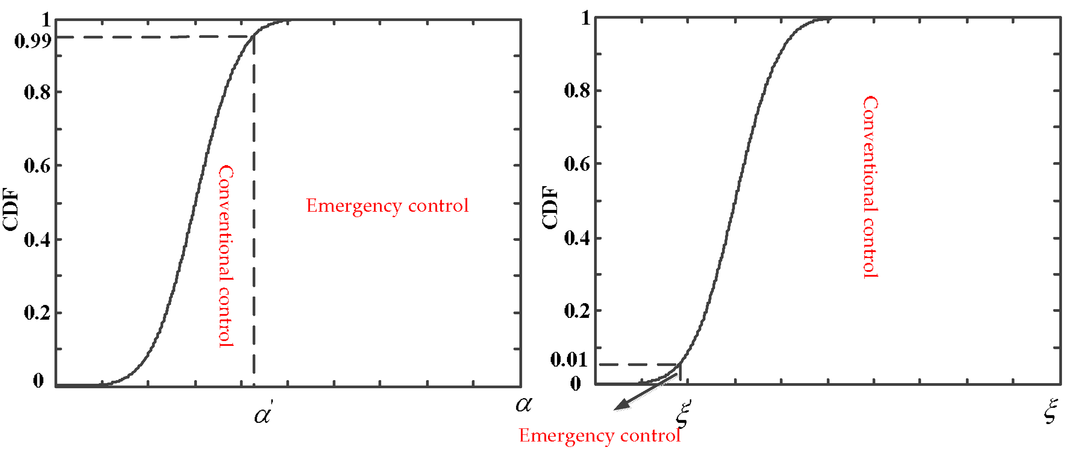
In practical applications, events that occur less than 1% of the time are considered to be small probability events. So, in order to satisfy the damping level of the system under multi-operating conditions, it can be considered that the system is stable under multi-operation conditions if the one-sided upper confidence limits of a 1% confidence interval of damping coefficients are less than zero, and the one-sided lower confidence limits of a 1% confidence interval of damping ratios are more than ξc, which is the damping ratio threshold of stable systems (The value of ξc in this paper is 3%).
Suppose that the one-sided upper confidence limits of a 1% confidence interval of damping coefficients, and the one-sided lower confidence limits of a 1% confidence interval of damping ratios are and , so:
According to the normal distribution characteristics, the and are shown as below:
So, the conditions of system dynamic stability under multi-operating conditions can be obtained by:
Transcribing Formula (4) into Formula (5), we get:
where and are defined as extended damping coefficient and extended damping ratio of the k-th oscillation mode, respectively. The system satisfies the dynamic stability under multi-operating conditions when Formula (4) or (5) is satisfied.
Previous studies [19,20] have demonstrated that the acceptable coefficients value of and in Formula (3) can be selected from the range of 3–4. This is because, as the local power grids become more closely linked, the frequency of the low-frequency oscillation gets lower. The higher coefficient means that more operating conditions will be considered within conventional control, and the band of frequency to optimize will become wider. However, it is difficult for the PSS2B to meet the requirements of the low-frequency band and high-frequency band simultaneously because of its structure. So, if more operating conditions are considered, the effectiveness of the parameter tuning might be diminished. The upper limits of and the lower limits of are set at 3.
3.2. The Site Selection of PSS Based on Probability Eigenvalue Sensitivity Analysis
The eigenvalue sensitivity is a quantity that can reflect the influences of the change of system parameters on the change of the eigenvalue. The probability eigenvalue sensitivity analysis is the derivative of eigenvalue sensitivity, which can be applied to the siting of the PSS under multi-operating conditions, because the sensitivities of , with respect to the PSS parameter will indicate which generator (having a PSS) is more effective on their movements.
Suppose that the sensitivity of to one of the parameters x of PSS is , the sensitivity of to one of the parameters x of PSS is , while and can be obtained by:
The probability eigenvalue sensitivity reflects the stability limit affected by the change of system parameters. If x is selected as a parameter of PSS, the and values will show the impact on the stability of the system by the location of the PSS and the change of the parameters. Under the normal distribution, reflects the distribution probability of , e.g., when . Thus, provides a direct measure for the system stability and its sensitivity is suitable and effective for a robust PSS design. can arrive at a similar conclusion. The and indicate that the increase of x can improve the stability of the system, otherwise, the stability will reduce. So, the ideal location of PSS under multi-operating conditions can be obtained by the comprehensive balance between the probability sensitivity ordering under the same parameters and the changing direction of the system stability caused by the PSS parameter changes.
3.3. Condition Judgment of Emergency Control
The method of parameter tuning of PSS under multi-operating conditions aims at the one-sided upper confidence limits of a 1% confidence interval of damping coefficients and the one-sided lower confidence limits of a 1% confidence interval of damping ratios meeting a certain threshold. However, the small-probability event of power system instability could be caused by the uncertainties. With the purpose of meeting the stability requirements under multi-operating conditions, the small-probability event of power system instability are defined as emergency control conditions, which will be provided for damping by the emergency control channel. So, the boundary between conventional control conditions and emergency control conditions can be denoted as Formula (7). The range of emergency control is:
In the process of the power system’s operation, the generators’ active power signal under the current operating conditions will be collected, and then the frequency, damping, and damping ratio can be identified by the Prony algorithm. The emergency control will be adopted when the eigenvalues of the system fall into the emergency control range, and do not meet the stability conditions. So, when the eigenvalues fall into the emergency control range and Formula (8) is satisfied, emergency control will be taken.
Formulas (4) and (7) correspond to the ranges of the conventional control and emergency control, respectively. The relationship between the two states is shown in Figure 2.
When the Prony algorithm is used to identify the low-frequency oscillation, the generators’ active power signal under current operating conditions will be collected. The k-th generators’ active power signal can be denoted as xk(n) (n = 0, 1, …, N − 1); thus, the sampling value signal of the generator can be fitted by a linear combination of P exponential functions:
The parameters of fitting function can be obtained by constructing the sample function matrix and the least square method, and then, the low frequency oscillation mode is identified.
3.4. Parameter Tuning of the Conventional Control Channels Considering Multi-Operating Conditions and Multi-Machine Coordination
Formulas (4) and (5) are the dynamic stability conditions of system under multi-operating conditions. According to the dynamic stability conditions, an optimal objective is expressed as:
where K is the PSS parameter vector, and and are extended damping coefficient and extended damping ratio to optimize, respectively. Meanwhile, μk and νk are the weight coefficients of the damping coefficient and damping ratio of k-th oscillation mode, respectively. The more unstable the eigenvalue, the larger the weighting coefficient will be.
To guarantee that the non-goal oscillation modes satisfy the stability conditions and the parameters of PSS meet the constraints, when setting the PSS parameters of goal oscillation modes considering multi-machine coordination and the damping coupling of different oscillation modes, the results optimized need to meet the following constraints:
where i is the non-goal oscillation mode, KSk is the magnification of PSS to optimize, and KSkmin and KSkmax are the minimum and maximum constraints of KSk, respectively. TSk,j is the k-th time parameter of PSS to optimize, whose minimum and maximum constraints are TSk,jmin and TSk,jmax, respectively.
3.5. Parameter Tuning of the Emergency Control Channels Considering Multi-Machine Coordination
The selector switch will select the emergency control channel and the parameters will be adjusted with the characteristic of current system online when the emergency control conditions are satisfied. So, the optimal objective can be denoted as follows:
where K, μk, and νk have the same meaning with Formula (10), αk and ξk are the damping coefficients and damping ratios of oscillation modes to optimize, respectively, and ξc is the damping ratio threshold of the stable systems.
Similarly, the optimized results need to meet the following constraints when the multi-machine coordination and the damping coupling of different oscillation modes are considered.
where i, KSk, KSkmin, KSkmax, TSk,j, TSk,jmin, and TSk,jmax have the same meaning as in Formula (11), and αi and ξi are the damping coefficient and damping ratio of non-goal oscillation mode, respectively.
4. The Solution of Parameter Tuning of E-PSS
The damping coefficients and damping ratios of the non-goal oscillation modes should be tested in the process of parameter tuning, considering damping coupling in a multi-machine system, and the analytic method cannot be used. So, the genetic algorithm is applied to adjust the parameters of PSS.
The magnifications KS1 () and the time parameters T1, T3, T5 (, , ) of PSS to optimize are set as the population, and the time parameters T2, T4, T6, , , and are given fixed values as 0.05 s in the algorithm. In the meantime, set the population to 200, the evolution generations to 500, the crossover probability to 0.5, and the mutation probability to 0.1. The fitness function of parameter tuning of the conventional control channels and the emergency control channels can be constructed as Formulas (14) and (15), since the values of the objective functions F1(K) and F2(K) are more than zero.
where C1 and C2 are extremely low positive constants, M1 and M2 are extremely large positive constants, and ω1 and ω2 are penalty factors. If the progeny parameters of PSS meet the constraints of Formulas (11) and (13), then the value of ω1 and ω2 would be zero, otherwise their value is one.
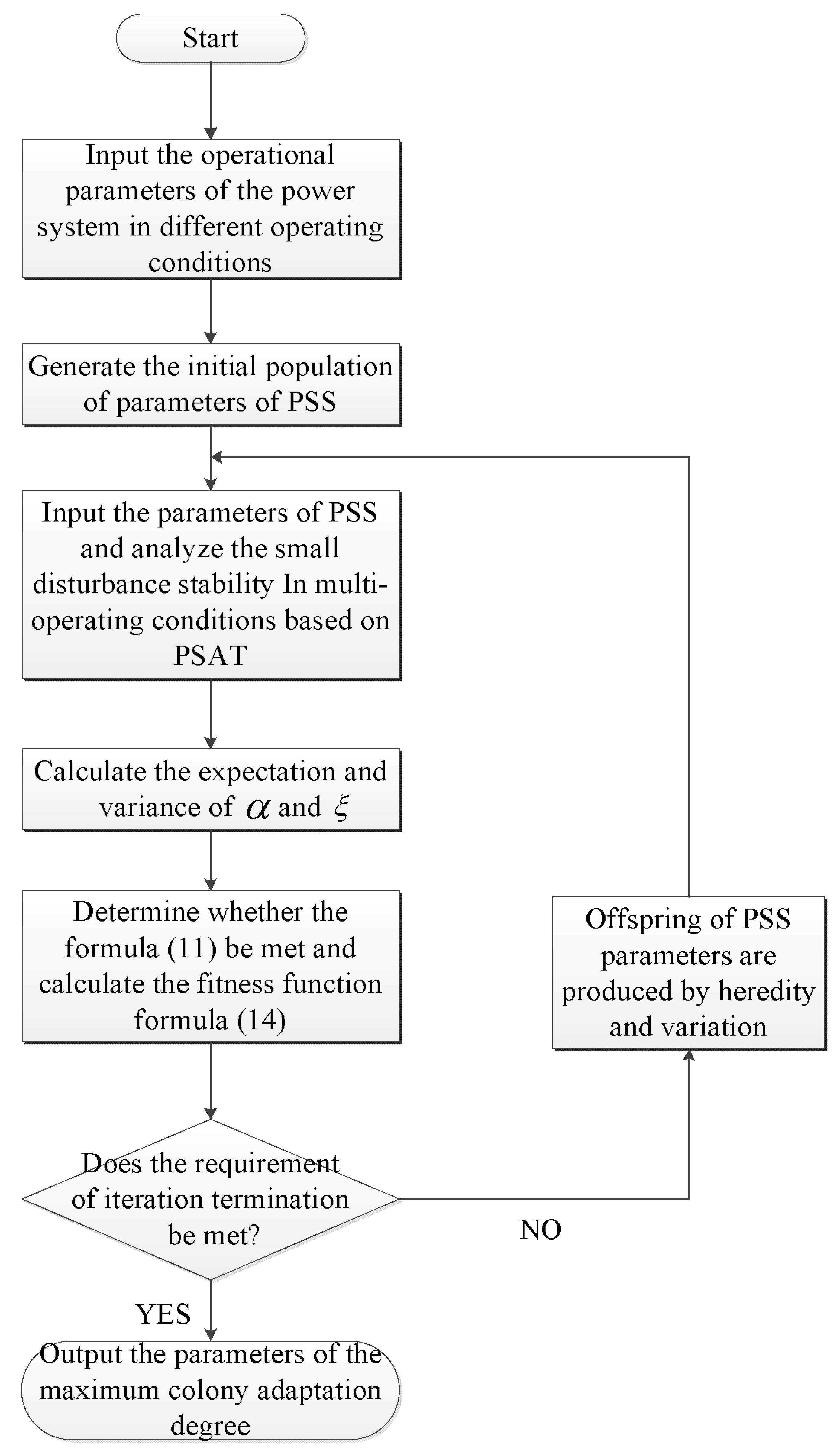
To solve the optimization problems in Formulas (10) and (12), the dynamic characteristics of the system in the current progeny parameters of the PSS are obtained by the PSAT toolbox; then, constraints (11) and (13) will be checked. If certain strong damping modes have deteriorated, the progeny parameters of the PSS would be weeded out, and the iteration terminates when the progeny parameters of the PSS is on steady state. The solution of Formula (10) is shown by a flow chart in Figure 3, and the solution of the optimization problems in Formula (12) is similar to those in Formula (10).
5. Case Studies
To verify the usefulness of the power system stabilizer with an emergency control function, which this thesis puts forward, and the accuracy of the parameter tuning of PSS considering multi-operating conditions and multi-machine coordination, a 10-generation 39-bus system is established based on MATLAB and its PSAT toolbox, and a series of simulations is carried out. The network topology of the system is shown in Figure 4.
To analyze the small disturbance stability of multi-operating conditions, the typical operating conditions (including the maximum and the minimum operating conditions in summer and winter) and many other operating conditions of the system are chosen to study. The expectation and variance of the damping coefficients and the damping ratios of the system before installing PSS are indicated in Table 1.
Table 1 shows that all of the low-frequency oscillation modes do not meet the conditions of dynamic stability set out in Formula (5), with the exception of the seventh mode before the PSS is installed in multi-operating conditions of the system. Since their values are less than three, that means that the instability may appear in certain operating conditions.
5.1. Site Selection of PSS
The x is set out as the magnification of PSS. To obtain the sensitivity of and to the magnification of PSS, assume that the PSS is installed in each unit, and that the partial derivative of and to the magnification of PSS when the magnification is set to zero are calculated.
The sensitivity of and to the magnification of PSS of each oscillation modes is shown in Table 2 and Table 3.
The sensitivity of the k-th oscillation mode’s and values with respect to the magnification of PSS are and , respectively, if the PSS is installed on the j-th power unit. Table 2 and Table 3 provide the information that the damping of the system may be deteriorated if the PSS is installed on units 2, 4, 5, and 7 to 10, because the values are less than zero, and the values are more than zero. Meanwhile, the installing of PSS on unit 6 can enhance the damping of oscillation modes 1, 3, 6, and 9 effectively, as the values are more than zero, and the values are less than zero. Likely, the conclusion that the damping of oscillation modes 2 and 4 will be strengthened if the PSS is installed on unit 1, and that the damping of oscillation modes 5, 6, and 8 can be improved by installing a PSS on unit 3 is able to be drawn from Table 2 and Table 3. So, the optimum locations for the PSS are units 1, 3, and 6 by comprehensively considering the damping coupling relationship of each oscillation mode.
5.2. Simulation of Parameter Tuning of the Conventional Control Channels Considering Multi-Operating Conditions and Multi-Machine Coordination
The results of the parameter tuning of conventional control channels are shown in Table 4 based on MATLAB and its toolkits.
The expectation and variance of the damping coefficients and damping ratios, α* and ξ* of the system are shown in Table 5 after the parameter coordinated tuning of the PSS.
Table 5 shows that all of the oscillation modes’ α* and ξ* are more than three, which means that the power system meets the conditions of dynamic stability in 99% of the operating conditions by parameter coordinated tuning.
5.3. Simulation of Parameter Tuning of the Emergency Control Channels Considering Multi-Machine Coordination
The emergency control should be carried out when extreme operating conditions and a lack of damping of the low-frequency oscillations occur in the system. The eigenvalues and the damping level of the system are shown in Table 6 when the conventional control channels are applied and an extreme operating operation suddenly appears.
Table 6 shows that the oscillation mode 8 is underdamping, which might result in the instability of the power system.
The weak damping and underdamping of the system, which belongs to the emergency control ranges, are detected by the Prony algorithm. The expectation and variance of the damping coefficients and damping ratios of the weak damping and underdamping low frequency oscillations before taking the emergency control are:
Judging the conditions of emergency control:
Formula (18) shows that the current conditions are in the emergency control range, and do not meet the stability conditions, so the emergency controls must be taken.
The parameter tuning of the emergency controls are shown in Table 7 according to Formulas (12) and (13).
The eigenvalues and damping of the system after emergency controls are indicated in Table 8.
It is shown that the dynamic stability of the system can be ensured through the emergency controls from Table 8, because all of the damping values are less than zero, and the damping ratios are more than three; namely, all of the oscillation modes are strong damping modes.
A regular laptop with 4G internal storage and i7630QM [email protected] GHz (Lenovo, Beijing, China) has been used in the simulation of emergency control, and the simulation time is about 20 min. With the development of the Wide Area Measurement System (WAMS) and the information communication technology, the main information of the power system can be obtained quickly, and it is promising that the calculation time would be effectively reduced and meets the requirement of emergency control if a device with more computing power is used, and better numerical arithmetic is applied in the calculation.
5.4. Analysis on the Adaptability of PSS Parameters
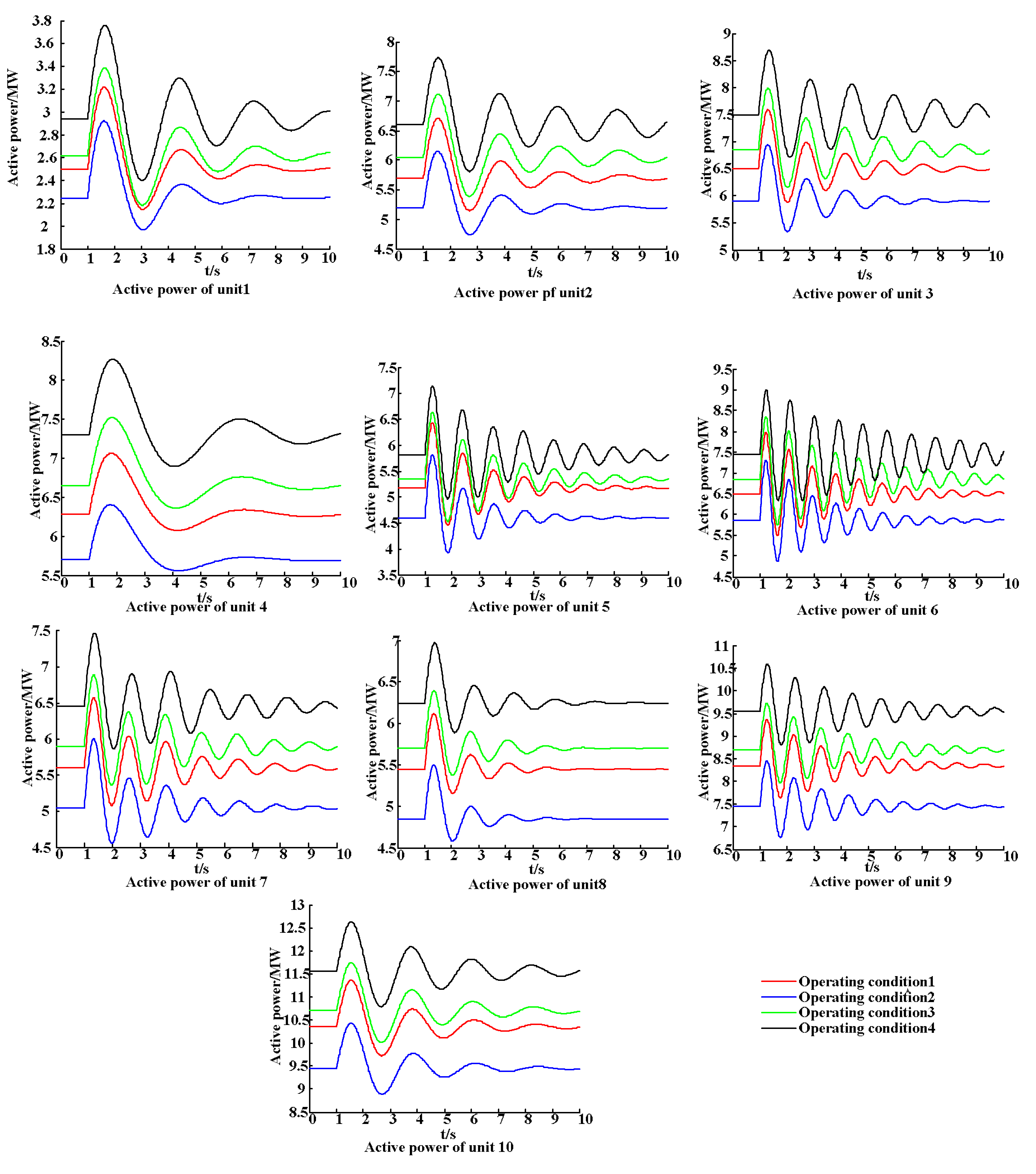
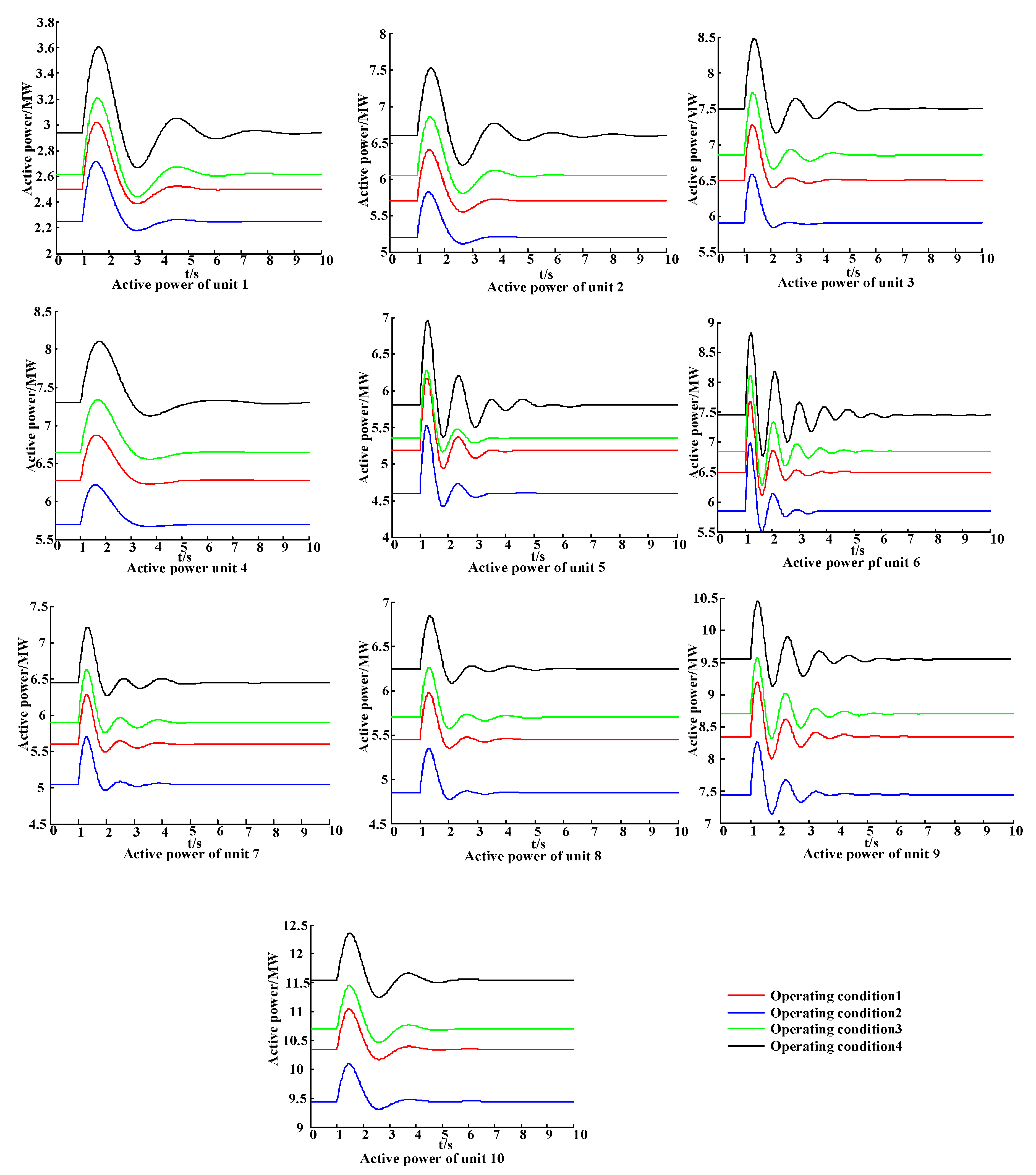
In order to verify further the effectiveness of the new proposed PSS and the adaptability of the PSS parameter tuning, the active power curves of units in four typical operation conditions, and an extreme condition before and after the PSS is installed are compared. The active power curves of units in four typical operation conditions before and after the PSS is installed are shown in Figure 5 and Figure 6, respectively.
Comparing Figure 5 and Figure 6, the power fluctuation of the units with the exception of unit 8 is serious before installing a PSS in four typical operation conditions where there is some disturbance. The oscillations calm down quickly with a robust PSS, and the amplitudes of the oscillations are substantially softened. Moreover, the stability of unit 8 is also enhanced. It was verified that the conventional control parameters of the PSS can adapt to changes in the operating conditions.
The active power curves of the units in an extreme condition before and after the PSS is installed are shown in Figure 7.
Figure 7 shows that there is strong oscillation in units 3, 4, 5, 6, 9, and 10, which only rely on the conventional control of the PSS when the emergency occurs in the system, and the emergency control must be carried out. The effectiveness of the emergency control parameters of the PSS is manifested in Figure 7.
6. Conclusions
To solve the problem that the conventional model and parameter tuning method of a power system stabilizer cannot adapt to modern power system development since the model power system’s operating conditions are complicated and changeable, a new emergency control model of PSS adapting to the multi-operating conditions of a local power grid and a method of parameter tuning considering multi-machine coordination are proposed. The judgment of emergency control, which divides all of the operating conditions of the power grid into conventional control conditions and emergency control conditions, is developed by a probabilistic eigenvalue analysis. Then, the PSS site selection is carried out in multi-operating conditions based on probability eigenvalue sensitivity analysis, which takes the damping coupling between each oscillation modes into consideration and prevents system damping from the deterioration caused by improper PSS installation. A method of parameter tuning the conventional control channels and emergency control channels that considers damping coupling is also studied. At last, an actual power distribution network is established based on MATLAB, and a series of simulations is carried out. These simulations prove that the new PSS provides enough damping for the system and satisfies the dynamic stability conditions in most of the operation conditions of the system. Furthermore, it also ensures the stability of the system via adjusting the parameters of the emergency control channels with the characteristics of the current system online when extreme operating conditions occur. More importantly, the E-PSS and its method of parameter tuning adapt to all of the operating conditions of the power system.
Author Contributions
W.H. conceived the structure and research direction of the paper; J.L. wrote the paper and completed the simulation for case studies; Y.J. provided algorithms; F.W. wrote programs and analyzed the data.
Funding
This research received no external funding.
Acknowledgments
We acknowledge the Smart Grid Research Institute at Wuhan University for devices.
Conflicts of Interest
The authors declare no conflict of interest.
Nomenclature
| PSS | Power system stabilizer |
| E-PSS | Power system stabilizer with emergency control |
| One of the conjugate compounds of the n-th order system | |
| The damping coefficient of the low-frequency oscillation mode | |
| The angular frequency of the low-frequency oscillation mode | |
| The damping ratio of the low-frequency oscillation mode | |
| The expectation of the damping coefficient of k-th oscillation mode | |
| The variance of the damping coefficient of k-th oscillation mode | |
| The expectation of the damping ratio of k-th oscillation mode | |
| The variance of the damping ratio of k-th oscillation mode | |
| The damping ratio threshold of stable systems | |
| The one-sided upper confidence limits of confidence level is 1% of damping coefficients | |
| The one-sided lower confidence limits of confidence level is 1% of damping ratios | |
| Extended damping coefficient of k-th oscillation mode | |
| Extended damping ratio of k-th oscillation mode | |
| The sensitivity of to one of the parameters of PSS | |
| The sensitivity of to one of the parameters of PSS | |
| The n-th signal of the k-th generators’ active power | |
| K | The PSS parameter vector to optimize |
| μk | The weight coefficients of the damping coefficient of k-th oscillation mode |
| νk | The weight coefficients of the damping ratio of k-th oscillation mode |
| KSk | The magnification of PSS to optimize |
| KSkmin | The minimum constraint of KSk |
| KSkmax | The maximum constraint of KSk |
| TSk,j | The k-th time parameter of PSS to optimize |
| TSk,jmin | The minimum constraint of TSk,j |
| TSk,jmax | The maximum constraint of TSk,j |
| The fitness function of parameters tuning of the conventional control channels | |
| The fitness function of parameters tuning of the emergency control channels | |
| C1, C2 | Extremely low positive constants |
| M1, M2 | Extremely large positive constants |
| ω1, ω2 | Penalty factors |
| PSAT | Power system analysis toolbox |
| UHV | Ultra high voltage |
| AC-DC | Alternating current- direct current |
| WAMS | Wide Area Measurement System |
References
- Abido, M.A. Robust design of multi-machine power system stabilizers using simulated annealing. IEEE Trans. Energy Convers. 2000, 15, 297–304. [Google Scholar] [CrossRef]
- Farahani, M. A Multi-Objective Power System Stabilizer. IEEE Trans. Power Syst. 2013, 28, 2700–2707. [Google Scholar] [CrossRef]
- Verdejo, H.; Gonzalez, D.; Delpiano, J.; Becker, C. Tuning of Power System Stabilizers using Multiobjective Optimization NSGA II. IEEE Latin Am. Trans. 2015, 13, 2653–2660. [Google Scholar] [CrossRef]
- Esmaili, M.R.; Khodabakhshian, A.; Panah, P.G.; Azizkhani, S. A New Robust Multi-machine Power System Stabilizer Design Using Quantitative Feedback Theory. Procedia Technol. 2013, 11, 75–85. [Google Scholar] [CrossRef]
- Ellithy, K.; Said, S.; Kahlout, O. Design of power system stabilizers based on μ-controller for power system stability enhancement. Int. J. Electr. Power Energy Syst. 2014, 63, 933–939. [Google Scholar] [CrossRef]
- Kamwa, I.; Grondin, R.; Trudel, G. IEEE PSS2B versus PSS4B: The limits of performance of modern power system stabilizers. IEEE Trans. Power Syst. 2005, 20, 903–915. [Google Scholar] [CrossRef]
- Morsali, J.; Kazemzadeh, R.; Azizian, M.R. Introducing PID-based PSS2B Stabilizer in Coordination with TCSC Damping Controller to Improve Power System Dynamic Stability. Electr. Eng. 2014, 836–841. [Google Scholar] [CrossRef]
- Rimorov, D.; Kamwa, I.; Joós, G. Model-based tuning approach for multi-band power system stabilisers PSS4B using an improved modal performance index. IET Gener. Transm. Distrib. 2015, 9, 2135–2143. [Google Scholar] [CrossRef]
- Krishan, R.; Verma, A. An efficient approach to tune modern power system stabilizers using harmony search. In Proceedings of the IEEE India Conference, New Delhi, India, 17–20 December 2015; pp. 1–6. [Google Scholar]
- Yaghooti, A.; Buygi, M.O.; Shanechi, M.H.M. Designing Coordinated Power System Stabilizers: A Reference Model Based Controller Design. IEEE Trans. Power Syst. 2016, 31, 2914–2924. [Google Scholar] [CrossRef]
- Gurrala, G.; Sen, I. Power System Stabilizers Design for Interconnected Power Systems. IEEE Trans. Power Syst. 2010, 25, 1042–1051. [Google Scholar] [CrossRef]
- Ke, D.; Chung, C.Y. Design of Probabilistically-Robust Wide-Area Power System Stabilizers to Suppress Inter-Area Oscillations of Wind Integrated Power Systems. IEEE Trans. Power Syst. 2016, 31, 4297–4309. [Google Scholar] [CrossRef]
- Marinescu, B.; Mallem, B.; Bourles, H.; Rouco, L. Robust coordinated tuning of parameters of standard Power System Stabilizers for local and global grid objectives. In Proceedings of the 2009 IEEE Bucharest PowerTech, Bucharest, Romania, 28 June–2 July 2009; pp. 1–7. [Google Scholar]
- Konara, A.I.; Annakkage, U.D. Robust Power System Stabilizer Design Using Eigenstructure Assignment. IEEE Trans. Power Syst. 2016, 31, 1845–1853. [Google Scholar] [CrossRef]
- Pulcherio, M.C.; Illindala, M.S.; Yedavalli, R.K. Robust Stability Region of a Microgrid under Parametric Uncertainty Using Bialternate Sum Matrix Approach. IEEE Trans. Power Syst. 2018. [Google Scholar] [CrossRef]
- Ayar, M.; Trevizan, R.D.; Obuz, S.; Bretas, A.S.; Latchman, H. A Robust Decentralized Control Framework for Enhancing Smart Grid Transient Stability. In Proceedings of the IEEE PES General Meeting, Chicago, IL, USA, 16–20 July 2017. [Google Scholar]
- Soliman, H.M.; Yousef, H.A. Saturated robust power system stabilizers. Int. J. Electr. Power Energy Syst. 2015, 73, 608–614. [Google Scholar]
- You, R.; Eghbali, H.J.; Nehrir, M.H. An online adaptive neuro-fuzzy power system stabilizer for multimachine systems. IEEE Power Eng. Rev. 2007, 22, 128–135. [Google Scholar] [CrossRef]
- Zhang, Y.; Chen, G.P.; Malik, O.P.; Hope, G.S. An artificial neural network based adaptive power system stabilizer. IEEE Trans. Energy Convers. 1993, 8, 71–77. [Google Scholar] [CrossRef]
- Ghosh, A.; Ledwich, G.; Malik, O.P.; Hope, G.S. Power System Stabilizer Based on Adaptive Control Techniques. IEEE Trans. Power Appar. Syst. 1984, PAS-103, 1983–1989. [Google Scholar] [CrossRef]
- Chung, C.Y.; Wang, K.W.; Tse, C.T.; Niu, R. Power-system stabilizer (PSS) design by probabilistic sensitivity indexes (PSIs). IEEE Trans. Power Syst. 2002, 17, 688–693. [Google Scholar] [CrossRef]
- Chung, C.Y.; Wang, K.W.; Tse, C.T.; Bian, X.Y.; David, A.K. Probabilistic eigenvalue sensitivity analysis and PSS design in multimachine systems. IEEE Trans. Power Syst. 2003, 18, 1439–1445. [Google Scholar] [CrossRef]
- Tse, C.T.; Wang, K.W.; Chung, C.Y.; Tsang, K.M. Parameter optimisation of robust power system stabilisers by probabilistic approach. IET Proc. Gener. Transm. Distrib. 2000, 147, 69–75. [Google Scholar] [CrossRef]
- Liu, S.; Messina, A.R.; Vittal, V. A Normal Form Analysis Approach to Siting Power System Stabilizers (PSSs) and Assessing Power System Nonlinear Behavior. IEEE Trans. Power Syst. 2006, 21, 1755–1762. [Google Scholar] [CrossRef]
- Abido, M.A. Optimal design of Power System Stabilizers Using Particle Swarm Optimization. IEEE Trans. Energy Convers. 2002, 17, 406–413. [Google Scholar] [CrossRef]
- Zanetta, L.C.; Cruz, J.J.D. An incremental approach to the coordinated tuning of power systems stabilizers using mathematical programming. IEEE Trans. Power Syst. 2005, 20, 895–902. [Google Scholar] [CrossRef]
- Kumar, A. Power system stabilizers design for multimachine power systems using local measurements. IEEE Trans. Power Syst. 2016, 31, 2163–2171. [Google Scholar] [CrossRef]
- Chitara, D.; Niazi, K.R.; Swarnkar, A.; Gupta, N. Cuckoo Search Optimization algorithm for designing of multimachine Power System Stabilizer. In Proceedings of the IEEE International Conference on Power Electronics, Intelligent Control and Energy Systems, Delhi, India, 4–6 July 2016; pp. 1–6. [Google Scholar]
- Attia, A.F. Online tuning based fuzzy logic controller for power system stabilizers. In Proceedings of the Nineteenth International Middle East Power Systems Conference, Cairo, Egypt, 19–21 December 2017; pp. 952–957. [Google Scholar]
- Mehrtash, M.; Kargarian, A.; Mohammadi, A. Partition-based bus renumbering effect on interior point-based OPF solution. In Proceedings of the IEEE Texas Power and Energy Conference, College Station, TX, USA, 8–9 February 2018; pp. 1–6. [Google Scholar]
Figure 1.
Mathematical model of the emergency control model of a power system stabilizer (E-PSS).

Figure 2.
Control sphere of parallel control channels.

Figure 3.
The solution of the optimization problems in Formula (10).

Figure 4.
Topology of the 10-generation 39-bus system.

Figure 5.
The active power curves of units in four typical operation conditions before the PSS is installed.
Figure 5.
The active power curves of units in four typical operation conditions before the PSS is installed.

Figure 6.
The active power curves of units in four typical operation conditions after the PSS is installed.
Figure 6.
The active power curves of units in four typical operation conditions after the PSS is installed.

Figure 7.
The active power curves of units in an extreme condition before and after the PSS is installed.
Figure 7.
The active power curves of units in an extreme condition before and after the PSS is installed.


Table 1.
Expectation and variance of α, ξ before installing a power system stabilizer (PSS).
| Modes of Oscillation | σα | α* | σξ | ξ* | ||
|---|---|---|---|---|---|---|
| 1 | −0.204 | 0.028 | 7.3 | 2.666 | 0.054 | −6.140 1 |
| 2 | −0.198 | 0.061 | 3.2 | 2.553 | 0.106 | −4.210 1 |
| 3 | −0.225 | 0.003 | 65.7 | 2.914 | 0.001 | −70.030 1 |
| 4 | −0.055 | 0.001 | 46.6 | 0.856 | 0.028 | −77.920 1 |
| 5 | −0.152 | 0.000 | 585.9 | 2.328 | 0.014 | −46.800 1 |
| 6 | −0.150 | 0.012 | 12.5 | 2.453 | 0.048 | −11.410 1 |
| 7 | −0.177 | 0.001 | 313.1 | 3.248 | 0.001 | 169.860 |
| 8 | −0.145 | 0.000 | 553.0 | 2.547 | 0.011 | −41.670 1 |
| 9 | −0.059 | 0.001 | 42.8 | 1.679 | 0.133 | −9.940 1 |
1 The extended damping ratio do not meet the conditions of dynamic stability.
Table 2.
Sensitivity of to .
| Units Modes of Oscillation | 1 | 2 | 3 | 4 | 5 | 6 | 7 | 8 | 9 | 10 |
|---|---|---|---|---|---|---|---|---|---|---|
| 1 | 0.000 | 0.000 | 0.000 | −0.094 | −0.346 | −0.274 | 0.384 | −0.689 | 0.784 | 0.000 |
| 2 | −0.021 | 0.000 | 0.000 | −0.011 | 0.607 | 0.000 | −0.062 | 1.004 | −0.955 | 0.000 |
| 3 | 0.000 | 0.000 | 0.000 | −0.021 | −0.255 | −0.309 | −0.444 | 0.000 | 0.267 | 0.000 |
| 4 | −0.010 | 0.000 | 0.000 | 0.000 | 0.000 | 0.000 | −0.010 | −0.021 | 1.136 | 0.000 |
| 5 | 0.000 | −0.031 | −0.156 | 0.000 | 0.000 | 0.000 | 0.000 | 0.000 | −2.382 | 0.000 |
| 6 | 0.000 | −0.021 | −0.021 | 0.010 | −0.021 | −0.021 | 0.000 | 0.000 | 0.000 | 0.221 |
| 7 | 0.000 | 0.000 | 0.000 | 0.000 | −0.042 | 0.000 | 0.000 | −0.010 | −0.031 | −0.239 |
| 8 | 0.000 | −0.010 | −0.063 | 0.000 | −0.021 | 0.000 | 0.000 | 0.000 | −0.042 | 0.000 |
| 9 | 0.000 | 0.000 | 0.000 | 0.000 | 0.000 | −0.010 | −0.010 | 0.000 | 0.000 | 0.000 |
Table 3.
Sensitivity of to .
| Units Modes of Oscillation | 1 | 2 | 3 | 4 | 5 | 6 | 7 | 8 | 9 | 10 |
|---|---|---|---|---|---|---|---|---|---|---|
| 1 | 0.000 | 0.000 | 0.000 | 1.198 | 4.904 | 4.129 | −3.221 | 12.328 | −3.424 | 0.000 |
| 2 | 0.079 | 0.000 | 0.000 | 0.278 | −8.366 | 0.000 | 0.710 | −10.577 | 1.671 | 0.000 |
| 3 | 0.000 | 0.000 | 0.000 | 0.229 | 2.210 | 2.793 | 12.961 | 0.008 | −2.641 | 0.000 |
| 4 | 0.127 | 0.000 | 0.000 | 0.000 | 0.000 | 0.000 | 0.166 | 0.355 | 11.676 | 0.000 |
| 5 | 0.000 | 0.455 | 2.395 | 0.000 | 0.000 | 0.000 | 0.000 | 0.000 | 17.169 | 0.000 |
| 6 | 0.000 | 0.319 | 0.378 | −0.178 | 0.343 | 0.324 | −0.005 | 0.000 | −0.005 | −4.983 |
| 7 | 0.000 | 0.000 | 0.000 | 0.000 | 0.729 | 0.000 | 0.000 | 0.161 | 0.557 | 19.655 |
| 8 | 0.000 | 0.139 | 1.094 | 0.000 | 0.347 | 0.000 | 0.000 | 0.000 | 0.793 | 0.000 |
| 9 | 0.000 | −0.011 | 0.000 | 0.310 | −0.006 | 0.010 | 0.315 | 0.000 | 0.000 | 0.000 |
Table 4.
Parameter coordinated tuning of PSS on units 1, 3, and 6.
| Units | KSK | T1 | T3 | T5 |
|---|---|---|---|---|
| 1 | 207.81 | 0.8324 | 0.0738 | 0.6076 |
| 3 | 26.89 | 0.4129 | 0.0678 | 0.3014 |
| 6 | 226.40 | 0.1451 | 0.0804 | 0.1062 |
Table 5.
Expectation and variance of α, ξ and α*, ξ* after installing a PSS.
| Oscillation Modes | σα | α* | σξ | ξ* | ||
|---|---|---|---|---|---|---|
| 1 | −0.574 | 0.007 | 77.400 | 7.001 | 0.019 | 213.410 |
| 2 | −0.335 | 0.002 | 138.400 | 4.314 | 0.012 | 108.270 |
| 3 | −0.274 | 0.001 | 218.900 | 3.536 | 0.004 | 129.600 |
| 4 | −0.499 | 0.001 | 387.900 | 7.360 | 0.174 | 25.130 |
| 5 | −0.348 | 0.002 | 156.500 | 5.247 | 0.095 | 23.730 |
| 6 | −0.222 | 0.001 | 189.300 | 3.512 | 0.025 | 20.350 |
| 7 | −0.188 | 0.024 | 7.800 | 3.343 | 0.108 | 3.180 |
| 8 | −0.196 | 0.022 | 9.000 | 3.531 | 0.114 | 4.660 |
| 9 | −0.132 | 0.009 | 14.700 | 3.639 | 0.075 | 8.550 |
Table 6.
Damping of power system before emergency control.
| Oscillation Modes | Eigenvalues | Damping Ratios (%) | Frequency |
|---|---|---|---|
| 1 | −0.5658 ± 8.1669i | 6.9114 | 1.2998 |
| 2 | −0.3391 ± 7.7747i | 4.3576 | 1.2374 |
| 3 | −0.2721 ± 7.6914i | 3.5358 | 1.2241 |
| 4 | −0.4639 ± 6.6927i | 6.9143 | 1.0652 |
| 5 | −0.3665 ± 6.5304i | 5.6036 | 1.0393 |
| 6 | −0.2367 ± 6.0123i | 3.9331 | 0.9569 |
| 7 | −0.1965 ± 5.4841i | 3.5812 | 0.8728 |
| 8 | −0.0455 ± 4.7217i | 0.9630 | 0.7515 |
| 9 | −0.1326 ± 3.5782i | 3.7035 | 0.5695 |
Table 7.
Parameter tuning of PSS taking emergency control.
| Units | KSK | T1 | T3 | T5 |
|---|---|---|---|---|
| 1 | 235.360 | 0.9257 | 0.8184 | 0.5155 |
| 3 | 92.173 | 0.0894 | 0.0279 | 0.0176 |
| 6 | 54.637 | 0.9868 | 0.5561 | 0.3503 |
Table 8.
Damping of power system after emergency control.
| Oscillation Modes | Eigenvalues | Damping Ratios (%) | Frequency |
|---|---|---|---|
| 1 | −0.2399 ± 7.7102i | 3.1103 | 1.227 |
| 2 | −0.2459 ± 7.4885i | 3.2813 | 1.192 |
| 3 | −0.3105 ± 6.9650i | 4.4540 | 1.109 |
| 4 | −0.1983 ± 6.2510i | 3.1708 | 0.995 |
| 5 | −1.6037 ± 4.4417i | 33.9601 | 0.707 |
| 6 | −0.2145 ± 5.5725i | 3.8466 | 0.887 |
| 7 | −0.8119 ± 5.0105i | 15.9957 | 0.797 |
| 8 | −0.1451 ± 4.6521i | 3.1179 | 0.740 |
| 9 | −0.5378 ± 3.3749i | 15.7363 | 0.537 |
© 2018 by the authors. Licensee MDPI, Basel, Switzerland. This article is an open access article distributed under the terms and conditions of the Creative Commons Attribution (CC BY) license (http://creativecommons.org/licenses/by/4.0/).
Share and Cite
MDPI and ACS Style
Hu, W.; Liang, J.; Jin, Y.; Wu, F. Model of Power System Stabilizer Adapting to Multi-Operating Conditions of Local Power Grid and Parameter Tuning. Sustainability 2018, 10, 2089. https://doi.org/10.3390/su10062089
AMA Style
Hu W, Liang J, Jin Y, Wu F. Model of Power System Stabilizer Adapting to Multi-Operating Conditions of Local Power Grid and Parameter Tuning. Sustainability. 2018; 10(6):2089. https://doi.org/10.3390/su10062089
Chicago/Turabian StyleHu, Wenping, Jifeng Liang, Yitao Jin, and Fuzhang Wu. 2018. "Model of Power System Stabilizer Adapting to Multi-Operating Conditions of Local Power Grid and Parameter Tuning" Sustainability 10, no. 6: 2089. https://doi.org/10.3390/su10062089
Note that from the first issue of 2016, this journal uses article numbers instead of page numbers. See further details here.