Fault Loop Impedance Measurement in Circuits Fed by UPS and Principle of Safety Protection


Faculty of Electrical and Control Engineering, Gdańsk University of Technology, 80-233 Gdańsk, Poland
*
Author to whom correspondence should be addressed.
Sustainability 2020, 12(23), 10126; https://doi.org/10.3390/su122310126
Submission received: 27 August 2020
/
Revised: 30 November 2020
/
Accepted: 1 December 2020
/
Published: 4 December 2020
(This article belongs to the Special Issue Uninterruptible Power Supplies (UPS))
Abstract
:This paper indicates a significant problem of uncertainty of fault loop impedance (FLI) measurement in circuits powered from uninterruptible power supply (UPS) (double-conversion AC-DC-AC). The correctly determined value of this impedance, related to the short-circuit current disconnection time and to the reference value, is one of the most important elements that determines the approval of an electrical installation and its receivers for operation. To define the principles of FLI measurement, several hundred measurements of the short-circuit loop impedance in the circuits fed by the UPS, in various UPS operation modes and with various FLI instruments, were made, which allowed for the definition of measurement rules that reduce the error in assessing the effectiveness of protection against electric shock by automatic disconnection of supply. Based on the analysis of voltage and current waveforms recorded during the real short-circuit tests in the circuit fed by the UPS, a proprietary algorithm for determining the short-circuit loop impedance has been proposed.
1. Introduction
Uninterruptible power supply (UPS) units are currently the most popular means of counteracting disturbances in the grid and protecting the load against the effects of disturbances [1]. Equipped with an energy storage system, most often in the form of lead-acid batteries in the VRLA AGM (valve-regulated lead-acid, absorbed glass mat) technology [2], they can provide uninterrupted power to the load requiring a continuous power supply. The effects of data loss, interruption of a technological line, or loss of human life due to a power outage are sometimes difficult to quantify, so the presence of UPS in such a situation is priceless [3]. In the power range from 10 kVA to over 6 MVA (in parallel operation), UPS units are manufactured in the AC-DC-AC double energy conversion technology, popularly known as online UPS [1,3].
In low voltage installations, there are disturbances in the form of short-circuits and overloads of electric circuits, but the available extensive knowledge allows for appropriate protection of electric circuits in this area [4,5]. Each electrical installation is subject to the procedure of verification during the first start-up, after modifications and periodic inspections in terms of meeting the requirements of the standard [6]. The purpose of verification of electrical installations is to check the conditions of proper protection of people against electric shock and safe operation of the electrical installation and the receivers supplied from it, including circuits fed by UPS.
One of the most important methods of verifying the electrical safety condition of the installation is the measurement of the earth fault loop impedance (FLI), which enables the verification of protection devices in terms of automatic disconnection of supply in the event of a short-circuit [4,5,6]. The choice of FLI measurement devices is large and their prices vary significantly. However, all measurement techniques are based on measuring the voltage drop during the test current forced by the instrument in the tested circuit. Depending on the value of the forced current, the measurement technique and the calculation algorithm, different measurement accuracy is achieved. When performing FLI measurements with various meters from different manufacturers, the discrepancy of the results reaches about 10%. It is completely different in case of performing FLI measurements in circuits fed by UPS. Here, the measurement results can vary by as much as 1000%. The issue of how to properly measure FLI in a circuit fed by UPS and how to properly assess the effectiveness of protection against electric shock is described in this article.
In the last two years, the authors have performed approx. 200 short-circuit tests in circuits fed by 30 kVA UPS with three-level inverter topology and 40 kVA UPS with two-level inverter topology [7,8]. Hundreds of FLI measurements were made with six different instrument models, from different manufacturers, forcing test currents from 3 to 140 A. The discrepancy in the results of the FLI measurements showed that it is necessary to research this area and explain the reasons for these discrepancies. To understand this problem, in the first place, Section 2 presents the principle of operation of the online UPS in the event of a fault in the circuit fed by UPS. The circuit length was being changed until UPS went from short-circuit to overload state. Significant differences were found in the operation of the UPS when a short-circuit condition was forced in the circuit fed by UPS during its normal operation, with the mains voltage present and during battery operation after switching off the mains power supply. Understanding the phenomena in the online UPS during short-circuits in the UPS output circuits made it possible to explain the discrepancies in the results of the FLI measurements, which are presented in Section 3. Based on the analysis of the FLI measurement results and the behavior of the online UPS during the faults in the UPS output circuits [9], Section 4 presents the method of proper FLI measurement in the circuits fed by UPS in the form of an algorithm, which at the same time enables the correct assessment of the effectiveness of protection against electric shock by automatic disconnection of supply. The proposed algorithm becomes a very good, and at present the only, tool for the correct assessment of the effectiveness of electric shock protection by automatic disconnection of supply in circuits fed by UPS.
References to the existing literature are modest because there are no publications strictly on the topic analyzed by the authors. The idea of measuring FLI has been described mathematically in detail, and the phenomena accompanying the measurement have been precisely explained [4,5,10]. Short-circuits and their effects in low-voltage installations are also described in detail both in terms of physics and mathematics, thanks to which various mathematical models have been created, simulating faults in electrical circuits [4,11,12,13]. Thanks to the models and standard [6], programs were created to select appropriate protection of the electrical installation, guaranteeing safety for people against electric shock and also protection and reliability for receivers [4,14]. The inverters and rectifiers operating in the UPS units have been thoroughly tested for the effects of external short-circuits, overloads, and surges, which enabled the design of appropriate protections in the form of high-speed fuse links and software current limitation in the converter control board [15,16]. Today’s converter designs are safe in operation and resistant to external factors such as short circuits, overloads, and surges [7,8,15]. Despite the knowledge and programs [17] that properly support the designer in designing electrical installations, there is a problem of the inspection that should be carried out in the installation with UPS.
The importance of the problem, presented in the paper, is really big. Every day, skilled people carry out inspections to verify if the overall assessment of the installation in terms of its suitability for continued use is satisfactory or not, according to the standard [6]. If not, recommendations are given by an inspector and they can be wrong, because of the lack of awareness of the problem presented in the article.
2. Short-Circuit in a Line Fed by Online UPS
Online (double conversion) UPSs make up the vast majority of global high-power UPS production in the world [1,2]. In the range from 10 to 1000 kVA, the UPS is manufactured in a three-phase version, and it is possible to connect several units in parallel to increase the power of the uninterruptible power supply system [3]. The occurrence of a short-circuit in the UPS-powered circuit causes a reaction depending on the UPS operating mode (double conversion, electronic bypass EB active, battery operation) and FLI (installation distance from the UPS output terminals to the fault point, wiring parameters, design solutions of transfer switch in UPS). The papers [9,10,18] analyzed partially the issues of impedance measurement, without a full analysis of transient states that occur during short-circuits in UPS-powered lines and which are a key element to the unambiguous assessment of the correctness of the UPS installation system from the electric shock protection point of view.
2.1. Short-Circuit in a Line Fed by Online UPS Working in Double Conversion Mode (AC-DC-AC)
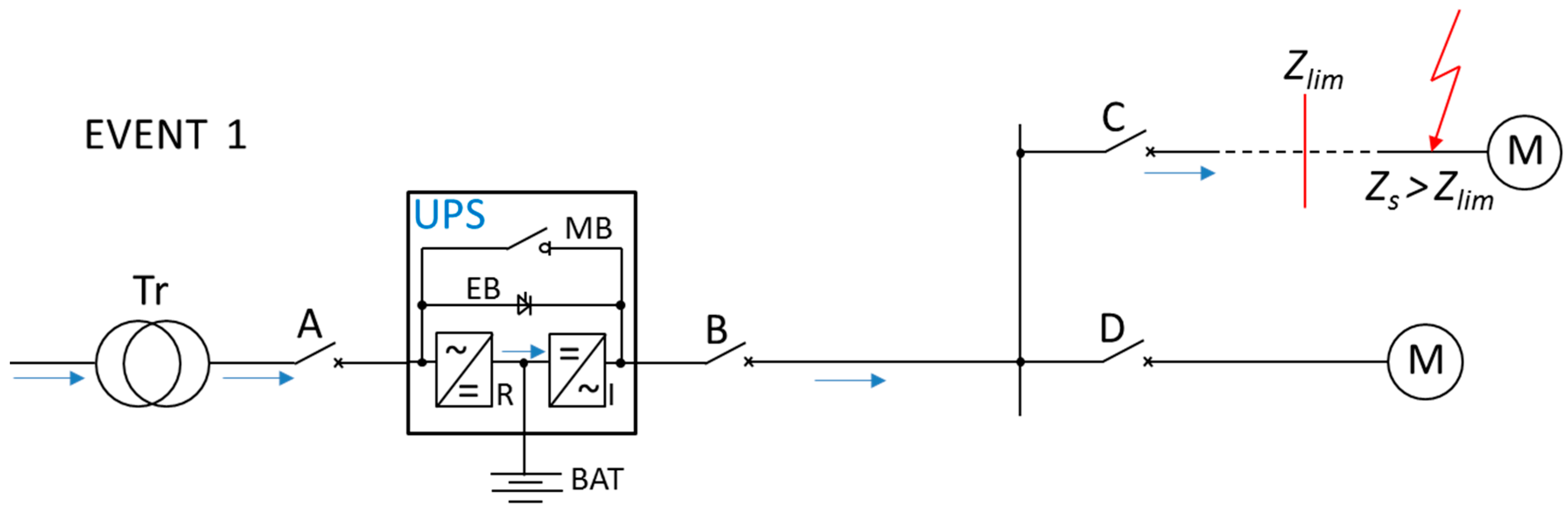
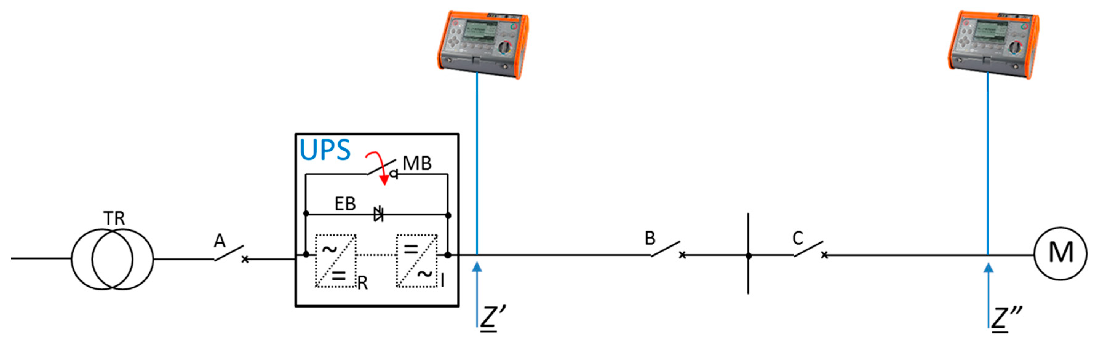
The online high-power UPS is considered to be the highest-class product according to the standard [19] (Section 5.3.4). By means of VFI-SS-111 indication, this standard determines the quality parameters of the UPS output voltage, which can be met only by the energy double conversion UPS technology (online). The online technology enables continuous energy conversion by a converter, i.e., rectifier and inverter connected in series (Figure 1). The battery BAT (or another DC source, e.g., a flywheel energy storage system) connected to the DC link, between UPS rectifier R and inverter I, allows uninterrupted operation of the inverter in the event of the rectifier stopping due to the mains powering off. If a certain inverter current value, typical for the UPS, is exceeded, the load protected by the UPS is uninterruptedly switched from the inverter to an electronic bypass (EB; also named static bypass or static switch). When there is no mains voltage and UPS operates from a battery, exceeding a certain value of the inverter current will cause inverter current limitation for a specified time. The short-circuit output current may or may not result in the inverter current limitation. The UPS response to the short-circuit in the output line depends on the impedance of the short-circuit loop Zs (total impedance from UPS output terminals to the fault point). From the point of view of UPS design features, the limit impedance Zlim can be calculated, above which the current flowing to the fault location during UPS double conversion operation will not switch the current to the EB line and, at most, will cause its overload. Figure 1 shows a diagram of two circuits with different impedances caused by different lengths of wires connected to the UPS output. The UPS operates in double conversion mode, with mains voltage present, and EVENT 1 concerns a distant short-circuit (Zs > Zlim), without the effect of switching to EB path.
For example, for a three-phase 30 kVA UPS, a metallic short-circuit at the end of a 2.5 mm2 wire with a length of at least 250 m does not cause the UPS to switch to EB. A distant short-circuit condition occurs when the impedance value of the circuit fed by the UPS is higher than the limit value Zlim and the forced fault current is less than the maximum inverter current for which UPS still stabilizes the output voltage with an accuracy of 1% (UPS overload condition). The limit value of FLI (Zlim), above which the UPS will still supply the circuit from the inverter at the earth fault location and not switch to EB (Figure 1), can be described by the formula:
where:
- Zlim—impedance limit value of the short-circuit loop, above which the inverter output voltage is stabilized to nominal value with an accuracy of 1% (typical for most UPSs);
- UnUPS—UPS nominal output voltage (typically UL-N = 230 V, for most countries);
- Iinvmax—max. inverter output current at which the voltage is still stabilized with an accuracy of 1% (typically Iinvmax = 150% InUPS, InUPS—UPS nominal output current).
In this situation, the value of the short-circuit current is determined by the quotient of the voltage at the UPS output (practically UPS nominal voltage UL-N) and the impedance of the short-circuit loop (FLI), i.e., the circuit calculated from the UPS output terminals to the fault point. In the case of a distant short-circuit (Zs > Zlim), the internal impedance of inverter, filters, and impedance components at UPS input do not affect the fault current, because the UPS output voltage can be regarded as an ideal voltage source.
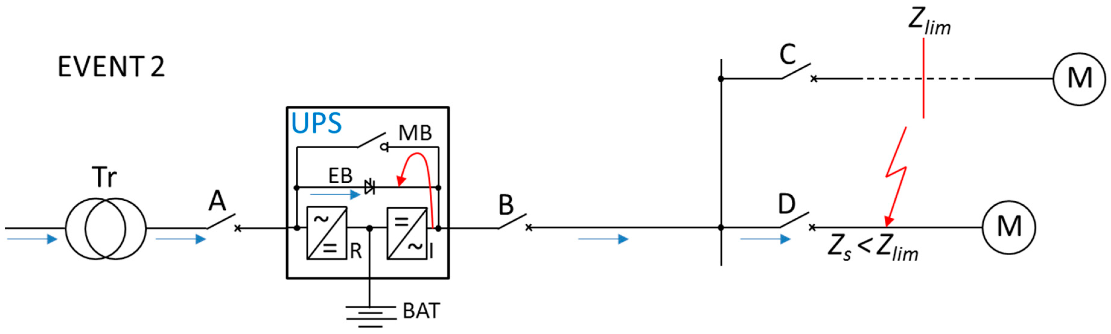
Due to the low short-circuit power of the UPS inverter and close distances of protective devices from UPS terminals (Zs < Zlim), in practice, there is no fault current sustained by the inverter when the mains voltage is present. A near short-circuit, whose impedance will force the current, will cause the UPS to switch to EB, which is the typical, most common short-circuit event in a circuit fed by UPS, operating in double conversion mode before the event. Figure 2 shows EVENT 2, corresponding to the condition Zs < Zlim.
For short-circuits that force UPS to switch to EB (Zs < Zlim), the FLI value Zs is (2):
where:
Zs = ZQ + ZTr + Zk1 + ZEB + Zk2
- Zs—total impedance measured from the source to the fault point;
- ZQ—system impedance;
- ZTr—transformer impedance;
- Zk1—substitute impedance of the cable line including the resistance of connections between the transformer and UPS;
- ZEB—EB path impedance;
- Zk2—substitute impedance of the cable line including the resistance of connections between UPS output and the fault point.
The presented formula shows that the fault loop impedance Zs is a typical value for a short-circuit in an electrical installation without UPS, which is increased only by the value of the additional EB path impedance, with thyristor impedance as its main component. Due to the thyristor impedance value, which is a few to several dozen of mΩ (for thyristor admissible short-circuit currents), the expected current resulting from the impedance Zs is close to that without UPS installed. The disproportion between expected currents becomes more noticeable when UPS is connected closer to the transformer when total impedance Zs is going to 0 Ω.
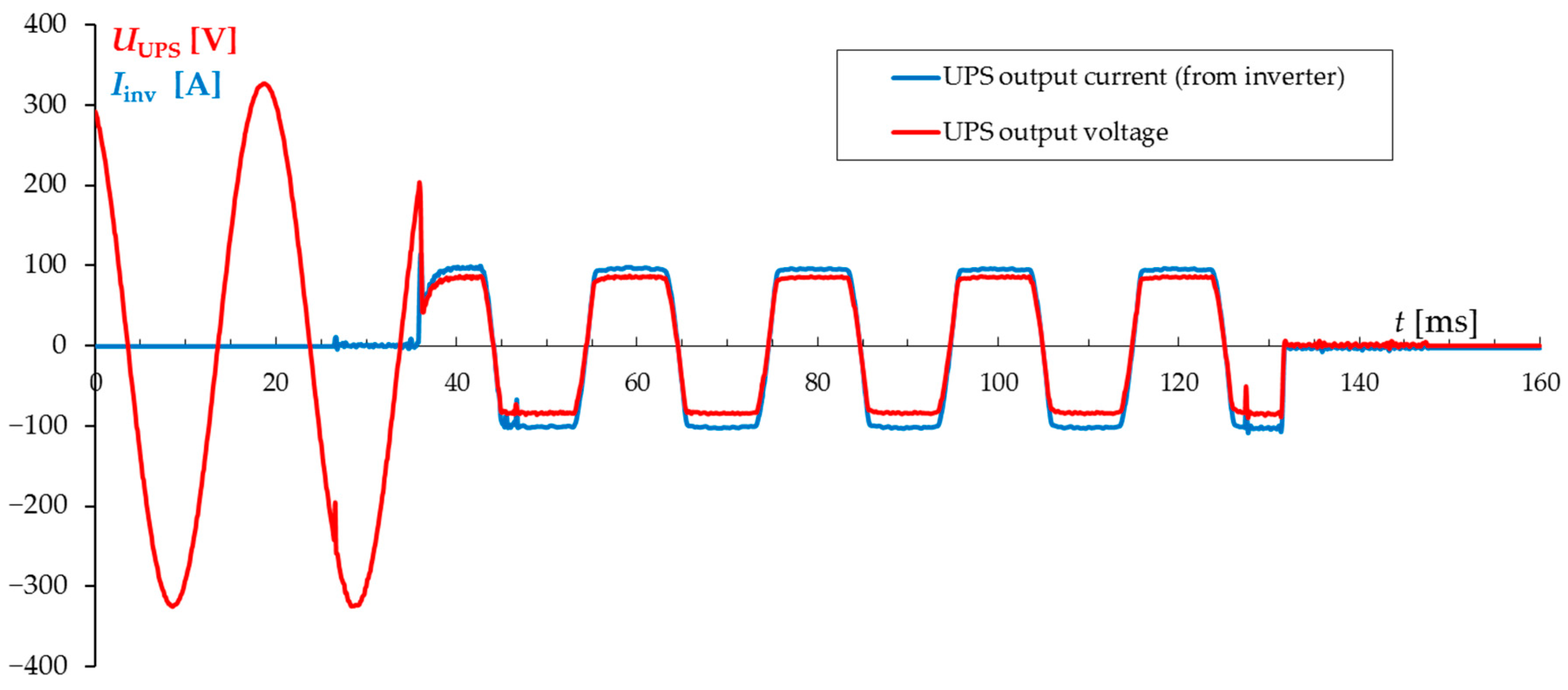
The phenomenon of switching from the inverter to EB during a short-circuit at UPS output is typical behavior for online construction and occurs when the UPS overload capacity is exceeded, usually above 150% of the UPS nominal current [3,13,14]. The time of switchover from the inverter to EB is about 3–5 ms (typical time for most of UPSs of different manufacturers). Sample of voltage and current waveforms recorded at UPS output during a near short-circuit for EVENT 2 are shown in Figure 3.
Just before the short-circuit event, UPS operates in double conversion mode, supplying the load (5 A) from the inverter. The load level does not affect the UPS behavior during short-circuit. At the moment of short-circuit, the inverter continues to supply the load (next to D protective device, EVENT 2, Figure 2), but with the current limited approximately to 100 A, which was the inverter limit current value of the UPS used in the test. This condition lasts for 3.3 ms, after which the thyristor EB is switched on (“b” point on the time axis) and the short-circuit current with a peak value of 320 A starts flowing until it is disconnected by protective device D. The current limited by the inverter may or may not trip protective device D, while the current flowing after switching to EB should trip breaker D, or possibly B or A in case of limited selectivity or improperly selected protection [14]. From the reliability of UPS system and electric shock protection points of view, the current value after switching to EB is important due to automatic disconnection of supply, and this is a result of loop impedance Zs (2), including the impedance ZEB.
2.2. Short-Circuit in a Line Fed by Online UPS Working in Battery Mode (DC-AC)
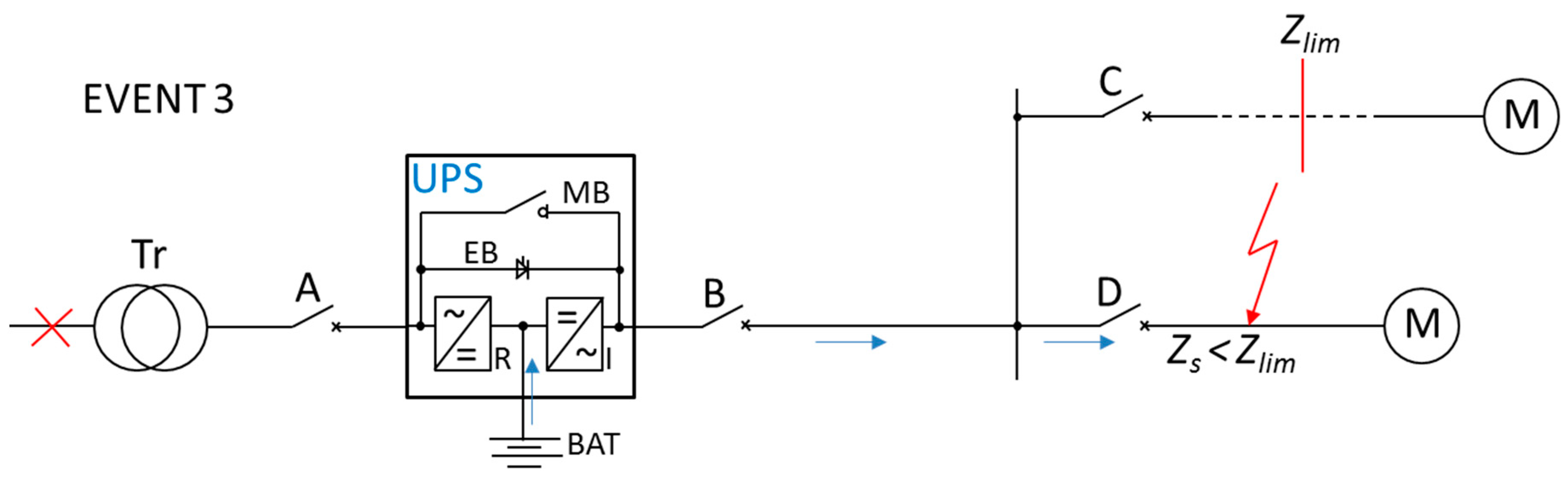
Like in the double conversion operation event, there are two short-circuit cases for UPS working in battery mode. The distant short-circuit event is identical to EVENT 1, described in Section 2.1, with the only difference that the inverter is powered from the battery as a result of the rectifier power off. The distant short-circuit in a line fed by UPS will cause the inverter overload at most. However, a near short-circuit for UPS working in battery mode will differ significantly from the situation of UPS double conversion mode, described as EVENT 2. Figure 4 shows a near short-circuit (EVENT 3), corresponding to the short-circuit condition Zs < Zlim, during battery operation of UPS.
A short-circuit at a point, for which FLI measured from UPS terminals to this point, which is less than Zlim results in the current limitation of the UPS inverter operating in battery mode. Unlike the double conversion operation with mains voltage present, there is no possibility of switching to EB, which forces the inverter to work for a short time, depending on the model of UPS and its manufacturer. Typically, UPS maintains a fault current, which is from 150% to 300% of the nominal UPS inverter current, for 100 to 2000 ms [3,20]. There are special UPS designs with significantly different parameters from typical inverter short-circuit capabilities. For example, a tailor-made inverter can maintain short-circuit current for 5 s.
If the values of the inverter limited current Iinvlim and FLI impedance Zs are constant under short-circuit conditions, then assuming that Zs < Zlim, only the voltage UUPS at UPS output terminals can vary (3):
where:
- UUPS—UPS output voltage between phase and neutral;
- Iinvlim—inverter limited current (typically from 150 to 300% of InUPS);
- Zs—fault loop impedance; comparing to Formula (2) Zs = Zk2, because EB thyristor is switched off (ZEB→∞).
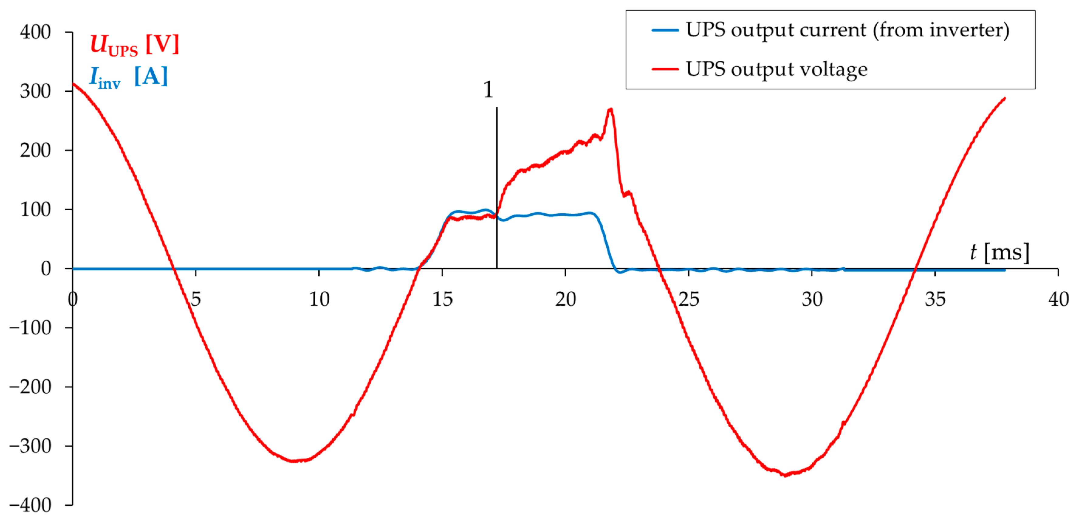
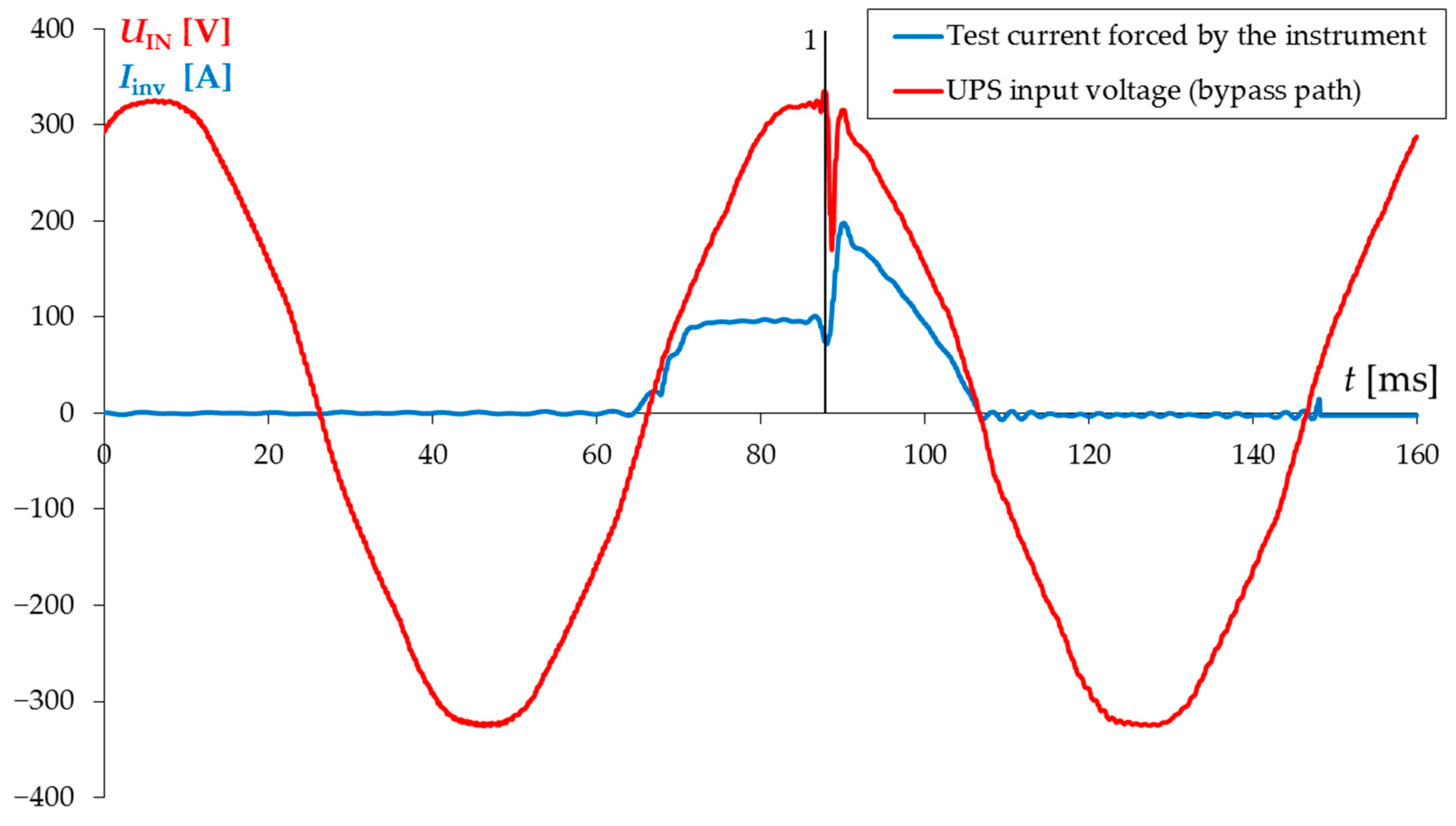
Figure 5 shows sample voltage and current waveforms recorded during a short-circuit in a circuit fed by UPS during its battery operation without protective device tripping.
For a near fault point, the quotient of the current in the EB path (after switching from the inverter to EB, when the mains are present) to the inverter limited current during UPS battery operation may range from several to several dozen times [16,17]. If the protective device was selected without taking into account the condition of the relatively small limited current Iinvlim, it may turn out that it would not be tripped during the short-circuit in a line fed by a UPS working in battery mode. It means that after the time set by the UPS manufacturer, if the reason of the short-circuit persists, the inverter will be automatically switched off and the UPS output voltage will be off. Maintaining the limited inverter current for time t = 100 ms during the short-circuit [21] (as in Figure 5) without protective device tripping is not a problem from the point of view of electric shock protection by automatic disconnection of supply, as the inverter will be switched off automatically in less than the time required by the standard [6]. However, this situation can be a serious threat to the reliability of the uninterruptible power system. No tripping of the appropriate protection within a specified time can be dangerous to the load supplied from the same UPS output, but also to the other lines in which no short-circuit fault has occurred. Lastly, a shut down in the UPS output means no voltage for all the loads.
The majority of currently manufactured UPSs maintain short-circuit current for about 500 ms in battery operation mode for power up to 200 kVA. For UPS power above 200 kVA, it depends on the manufacturer and customer’s requirement. This means that in some cases, no protection tripping results in switching off the fault current after a longer time than required by the standard [6]. Consequently, the evaluation of the effectiveness of electric shock protection must include a check whether the touch voltage Ud in the UPS output installation is not higher than that specified by the standard [6] as acceptable. The risk of the touch voltage being higher than acceptable should lead to such selection of a protective device that, for EVENT 3, the breaker effectively switches off the fault current in a time not longer than specified by the standard (0.4 s for a low-voltage 230 V installation). Figure 6 shows the sample operation of a correctly selected S type B16 circuit breaker during a short-circuit at the output of the UPS working in battery mode.
3. UPS FLI Measurement in Lines Fed by UPS
FLI measurement is the starting point for evaluating the effectiveness of electric shock protection by automatic disconnection of supply in appropriate time [6]. Despite differences in measurement techniques and computational algorithms, the currently manufactured instruments measure FLI in electrical lines with relatively high accuracy, and the results of their measurements vary from a few to several percent. Thanks to this, the evaluation of the effectiveness of electric shock protection in circuits with no UPS is correct, despite the use of instruments of various models and manufacturers. However, in the case of UPS-powered circuits using instruments forcing different test currents, significantly greater differences in FLI measurements during the tests (even over 1000%) were noticed. Based on the analysis of transient states of currents and voltages in circuits fed by UPS, the reasons for the discrepancy between FLI measurement results and their impact on the reliability of UPS systems and the evaluation of the effectiveness of electric shock protection by automatic disconnection of supply have been determined. A correct way to perform the FLI measurement and its evaluation depends on UPS operation mode.
3.1. FLI Measurement during UPS Double Conversion Operation (AC-DC-AC)
For distant short-circuits (EVENT 1, Zs > Zlim) during UPS operation in double conversion mode, the impedance of FLI calculated from UPS terminals to the FLI measurement point is of high importance. Due to the fact that the UPS output voltage is stabilized with an accuracy of ±1%, the impedance of the inverter and upstream UPS circuits, including the source, i.e., a transformer, do not affect the fault current in the UPS output, which in this case (Zs > Zlim) can be described with Formula (4):
where:
- Zk2—FLI calculated from UPS output terminals to the measured point;
- UnUPS—nominal UPS output voltage (from inverter, typically 230 V);
- Iinv—inverter current, which does not exceed the UPS inverter overload capacity (typically Iinv < 150% · InUPS).
Practical measurement of Zk2 is possible by performing two FLI measurements, which is presented in Figure 7.
The Zk2 value can be determined as the difference between the measured real and imaginary values Zk2 = Z’ − Z” on UPS terminals, and at a required test point distant from the UPS output. Both measurements should be made with maintenance bypass (MB) switch closed, as the FLI measurement with the inverter running results in a large spread of the measured values. The closed MB switch (Figure 1) eliminates the influence of UPS electronics on the measurement.
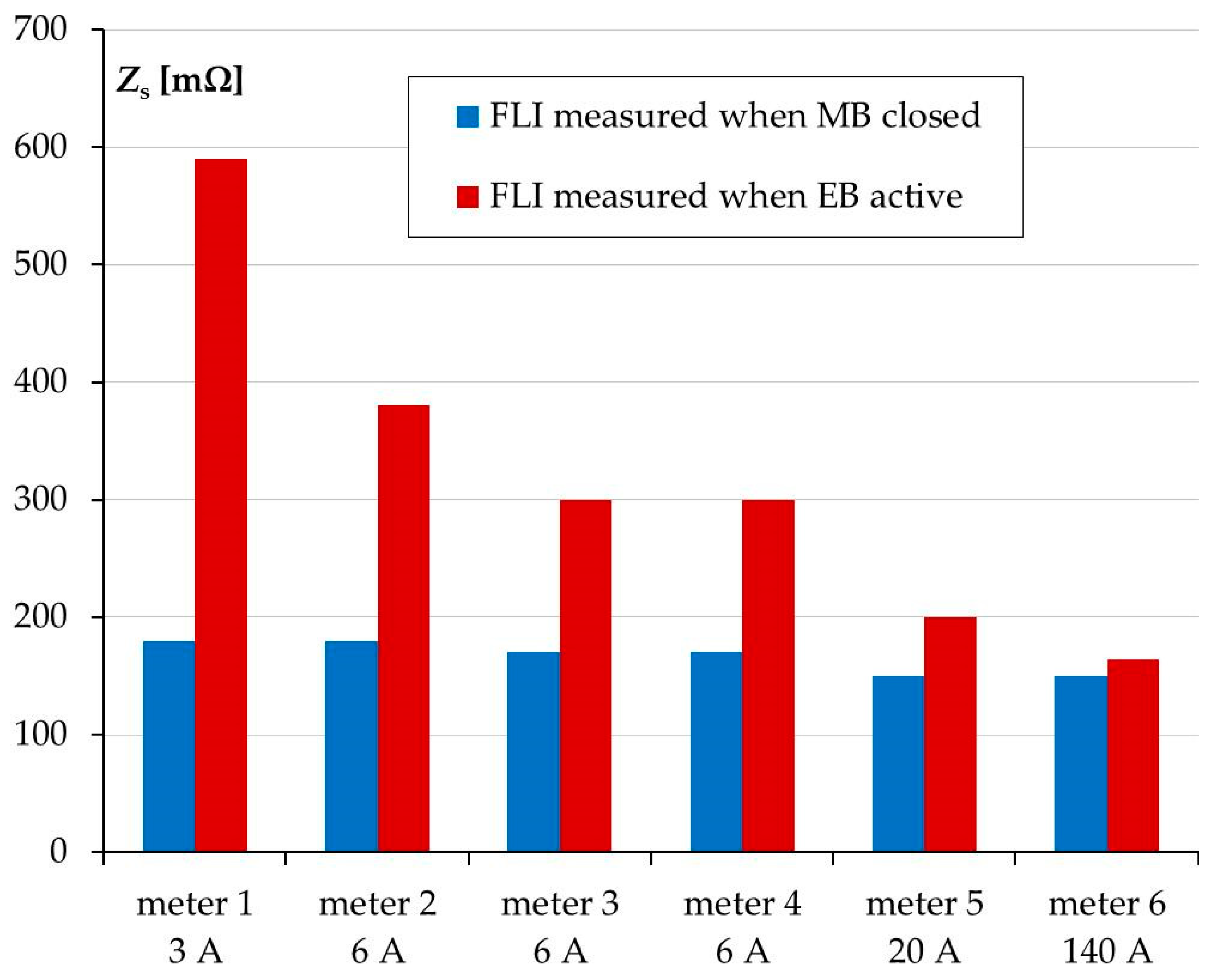
According to the analysis of the short-circuit condition in Section 2.1 for EVENT 2 (Figure 2), FLI measurement in UPS operating in double conversion mode is not reasonable. The fault current in real conditions will not be generated by the inverter but will flow from the mains transformer through the switched-on thyristor EB to the fault point. To force the UPS to operate in active EB line status to perform the FLI measurement, it is necessary to activate the EB path. It can be done by ECO (Economy) mode or another EB activation option available in the UPS menu. Tests performed with a number of 30 kVA UPSs and six different instruments forcing test currents from 2 to 140 A delivered FLI measurement results for UPS in active EB mode. These results were compared with those obtained in MB switch closed condition (Figure 8).
During the test, the instruments 1 to 6 forced, respectively, the following test currents: 2, 6, 6, 6, 20, and 140 A. The measurement was carried out with no load at UPS output. Under real conditions, when the UPS is being commissioned, FLI measurements in UPS-powered circuits are often performed without any load. In such conditions, it was found that the measured FLI results were significantly higher for the UPS set in active EB mode when the used instruments forced currents at the level of several amps. For the closed MB switch, the results of FLI measurements carried out with instruments 1–6 differed by a maximum of 15%, while for the active EB by almost 400%. FLI measurement performed with meter 6, which forced 140 A test current, allowed the analyzed UPS to get the result closest to the real value of ZEB impedance in the short-circuit condition. Increasing the load at UPS output resulted in a decrease of the difference between FLI values measured using different instruments and their approach to the value measured by meter 6. The difference in FLI measurements performed with meter 6 for MB closed and EB active was relatively small and indicated the presence of additional impedance of around 15 mΩ in the EB path. Both results, shown for MB closed and EB active by meter 6, were very close to real values.
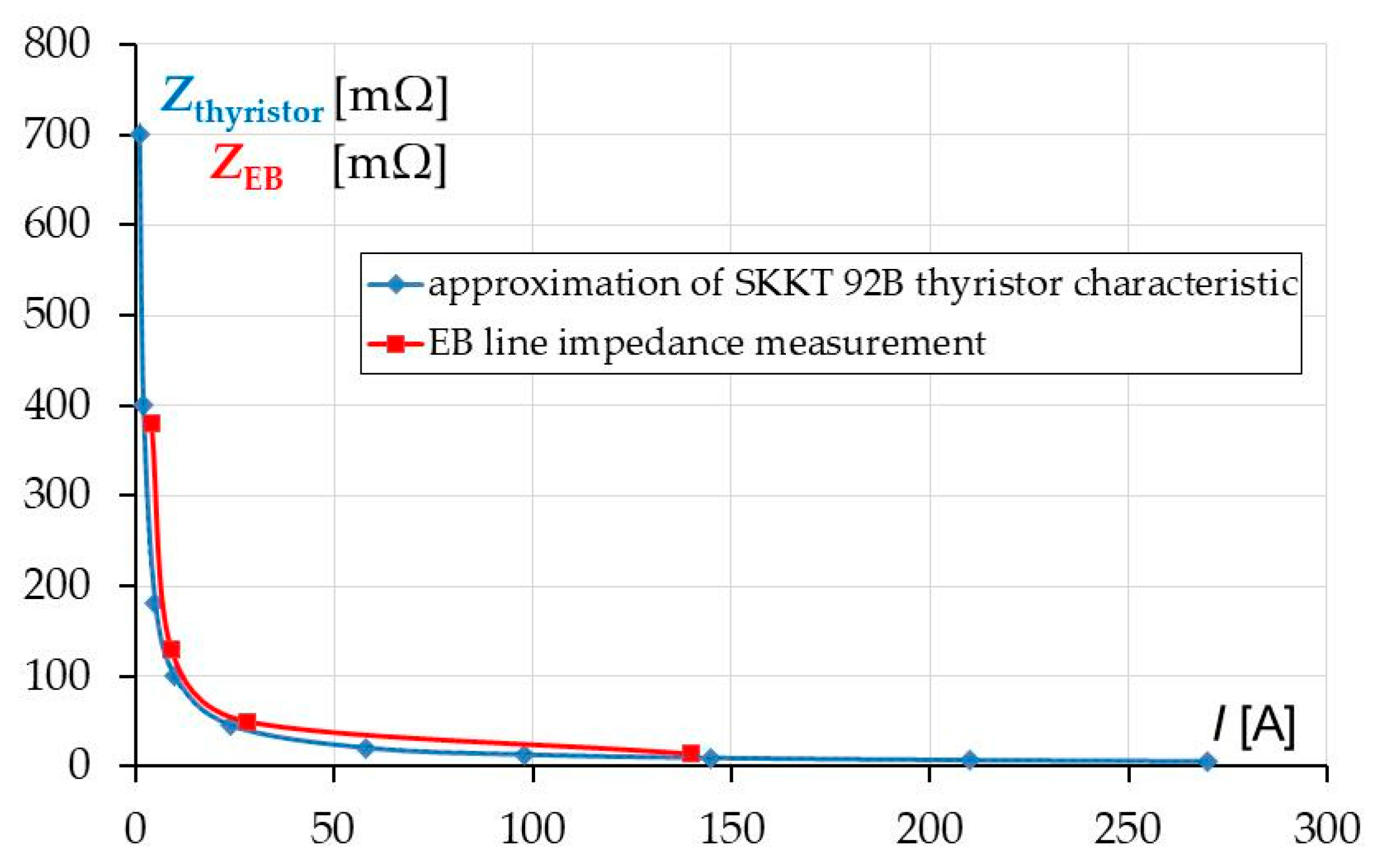
Figure 9 shows the measured impedance EB, whose main component is the thyristor impedance Zthyristor, as a function of load current. The other characteristic Zthyristor = f(I) was plotted by approximating the manufacturer’s characteristic It = f(Ut) for SKKT 92B thyristor, installed in the tested 30 kVA UPS.
The clear overlapping of these two characteristics confirms the presence of variable, current-dependent thyristor impedance. A relatively high value (of up to 0.7 Ω in Figure 9) of this impedance is particularly important at low test currents forced by the instruments when UPS is working with no load, as the smaller the measuring current, the greater the FLI value measured by the instrument. That is why decreasing the value of the expected fault current leads to an incorrect evaluation of the electric shock protection in UPS-powered circuits by automatic disconnection of supply. The operation of UPS with no load or with a few percent of nominal load value, also unbalanced load (e.g., 50%, 30%, 2%), which occurs quite frequently in real operating conditions, makes it impossible to evaluate the protection for safety from the measured FLI result correctly. Higher test currents of the meters also do not guarantee a correct FLI measurement, as the measurement carried out in a circuit fed by, for example 1000 kVA UPS, operating without load, will be burdened with an error resulting from the increased impedance of the thyristor EB for the instrument test current, which is a few percent of the UPS thyristor nominal current ITRMS.
A correctly measured FLI value in active EB mode is only a few percent higher compared to the measured value with MB switch closed. With a real short-circuit in the UPS-powered circuit in double conversion operation (EVENT 2), switching to EB line means a current flow comparable with, or significantly higher than, the nominal current ITRMS. In such conditions, the thyristor impedance is calculated from several to several dozen of mΩ for the vast majority of currently manufactured thyristors, used in different UPS. Based on the available data of the thyristor installed in the EB line, the Formula (5) can be derived to calculate, at any point of the UPS-powered circuit, the impedance Zs, which will result in the expected fault current, assuming the presence of the mains voltage.
where:
Zs ≈ ZMB closed MEASURED + Zthyristor CALCULATED
- Zs—determined FLI at any point of UPS-powered circuit;
- ZMB closed MEASURED—measured FLI value when MB is closed;
- Zthyristor CALCULATED—thyristor impedance value read from the characteristic Zthyristor = Ut/It for the largest current value, visible on the characteristic.
Zthyristor impedance can be determined from the characteristic Zthyristor = Ut/It by approximating It = f(Ut) for the maximum currents visible on this characteristic. If one assumes the same FLI value at UPS output for active EB line as for closed MB switch:
then a slight error is made, which results in an increase of the expected fault current. This, in turn, can lead to an incorrect assessment of the electric shock protection by automatic disconnection of supply. For a long distance of cables connected, when the impedance is high (for example 1 Ω), Formula (6) is true because thyristor impedance is only around 1% of Zs, but for low impedance measured by the instrument (for example 0.1 Ω), thyristor impedance is around 10% of Zs, which cannot be ignored.
Zs ≈ ZMB closed MEASURED
Table 1 presents the results of FLI measurements made with six instruments in different UPS operation modes and compared with the calculated Zs value according to the Formula (5).
The results in Table 1 were averaged on the basis of three consecutive measurements carried out under the same conditions. The measured values of Z1 differed from each other more than 10 times. They were carried out during double conversion UPS mode (AC-DC-AC). Instrument no. 6 forced the UPS to switch from inverter to EB path, which is visible in Figure 10.
The value 478 mΩ shown on the meter is true but it is not possible to draw any true conclusions on its basis. That is why it is important to understand the UPS operation. The FLI values for UPS working in battery mode were very close to Z1 (in double conversion) with the exception of instrument 6, which during the measurement caused the current limitation of the inverter as the only meter in the group.
Z2 are the values measured when UPS was working in EB active mode and Z3 when MB closed, which is shown in Figure 8. Impedance Z4 is the difference between measured values Z2 and Z3. ZEB(I) characteristic, which was determined on the basis of Z4, is presented in Figure 9. In the last column, the impedance value of Z5 was calculated according to Formula (5). The impedance Zthyristor CALCULATED read from the Z = f (I) characteristic was 10 mΩ for current 140 A (Figure 9), which was the closest result to the real value. Z5 values differed from each other by approx. 15%, similarly to the results of FLI measurement with MB closed (Z3), regardless of the instrument manufacturer and the value of the test current forced by the meter. It means that FLI measurements carried out with MB closed are close to real value in general (the closest one is obtained by meter 6 with 140 A test current), and the same error is made using Z5 calculation based on Formula (5).
3.2. FLI Measurement during UPS Battery Operation (on Battery DC-AC)
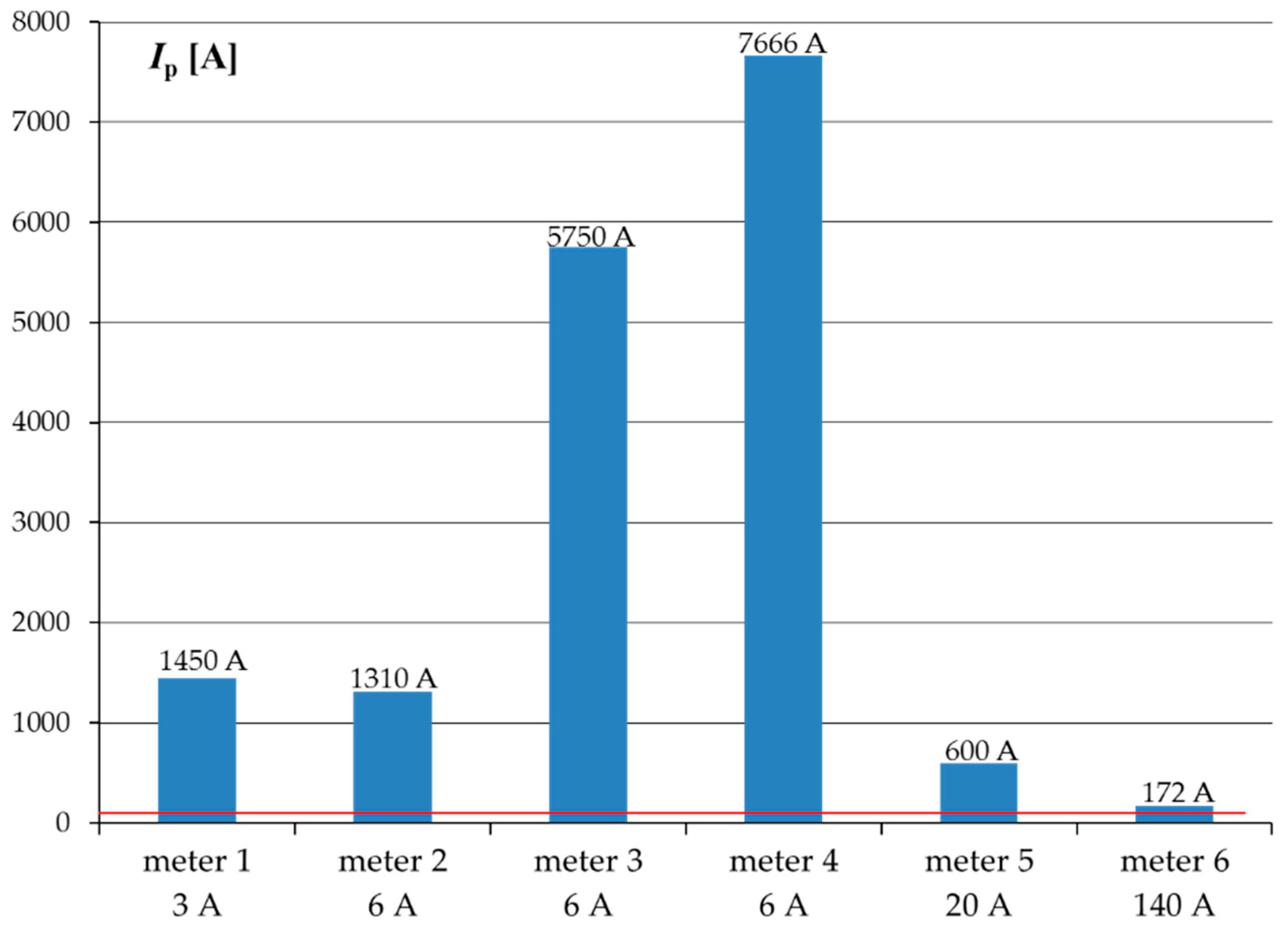
The results of FLI measurements carried out with different instruments in UPS battery operation mode differed from each other more than 10 times. Some of them indicated the impedance close to 0 Ω (e.g., 30 mΩ), which could lead to the conclusion that the expected short circuit current could be over 7 kA, while the real current measured at UPS output during the short-circuit test was Iinvmax1 = 98 A. The impedance calculation algorithm used by various instruments is based on the forced current and voltage measurement, with particular emphasis on voltage drop during test current forcing [9,10,18]. The UPS inverter, loaded with the instrument test current, controls the switching of IGBT transistors to stabilize the output voltage with the highest accuracy (typically 1%, with the response time of single milliseconds). In these conditions, the instrument voltage measurement is disturbed and the expected current values are much higher than those measured at the same point, but for the UPS with MB switch closed. The tests confirmed that the current limited by the UPS inverter during the short-circuit at UPS output is much smaller than the current during the same test with MB switch closed when the mains voltage is present.
The expected fault currents, calculated from FLI measured values, by six instruments used in the test, are presented in Figure 11 (UPS was working in battery mode, no mains voltage present).
The tests confirmed that the currents limited by the UPS inverters during the short-circuit at their output were much smaller than the currents that would flow if the test was carried out with the MB switch closed and mains voltage present. The conclusion is that the FLI measurement in the UPS-powered circuit during its battery operation (for EVENT 3, Zs < Zlim) is not reasonable, because the measured expected fault current significantly varies from real Iinvlim value (inverter limited current) defined by the UPS manufacturer.
The same tests carried out with a cable connected to the UPS resulted in a smaller discrepancy of the measured values. The higher the impedance of the cable connected to the UPS terminals, the smaller the discrepancy of the measured values. When the impedance of the cable reached 1 Ω, the discrepancy of the measured values was reduced to 30%, which was still more than 15% obtained with UPS manual bypass MB closed. It means that the error is bigger when the impedance of the cable connected to the UPS terminals is lower or the distance between FLI measured point and UPS output terminals is closer.
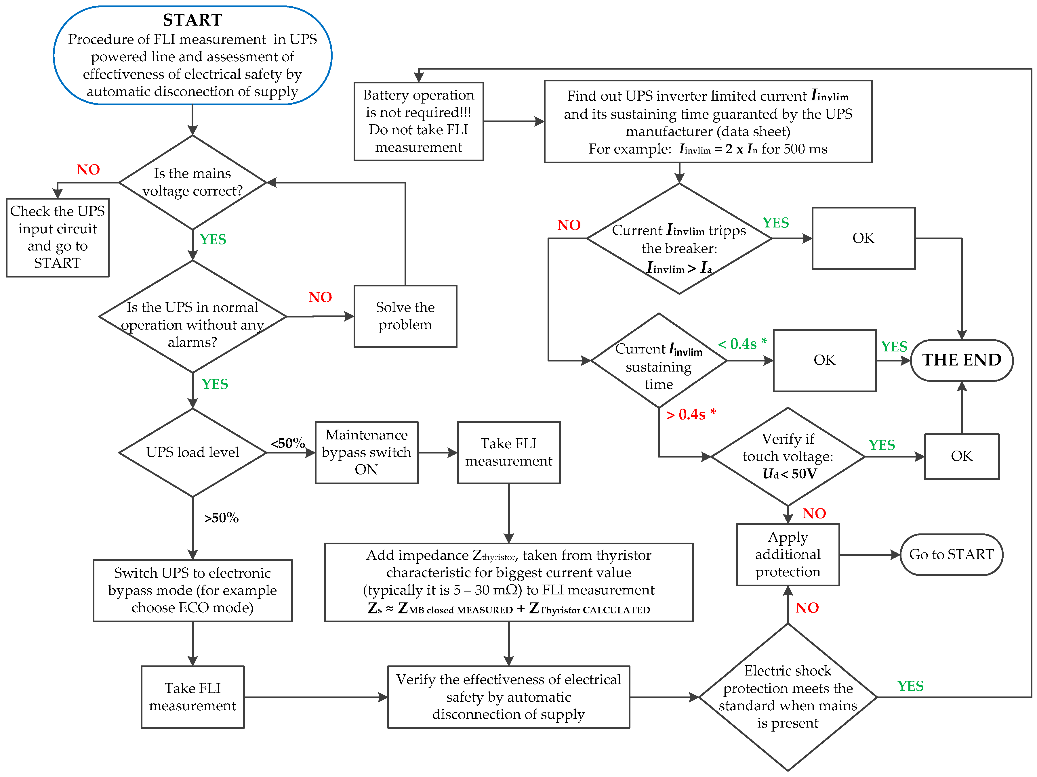
4. FLI Measurement and Assessment of the Effectiveness of Electrical Safety by Automatic Disconnection of Supply Algorithm in Lines Fed by UPS
Based on the analysis of FLI measurement results and transient states in the UPS during the short-circuit, an algorithm for determining FLI assessment of the effectiveness of electrical safety by automatic disconnection of supply in UPS-powered circuits is proposed (Figure 12).
The assessment of the effectiveness of electric shock protection includes two UPS operation modes, i.e., double conversion mode and battery mode. The procedure includes the FLI measurement only for the active EB mode with load level of at least 50% (assumed contractual value). For this load level, the thyristor impedance on the characteristic Zthyristor = f(I) is located in the part close to the X axis, which means that its value, estimated in several or dozens of mΩ, is close to the real value during the short-circuit. If the UPS load is below 50% of the rated value, an error resulting from overstating the FLI will lead to an incorrect assessment of the effectiveness of electric shock protection by automatic disconnection of supply. In this case, another FLI measurement, performed according to the procedure with MB closed, is needed to determine FLI in accordance with Formula (5). The battery mode does not require any FLI measurement. Determining the value of the expected fault current only involves reading the inverter limited current Iinvlim, given in UPS manufacturer’s data sheet. Based on this value, it is sufficient to verify whether the current Iinvlim trips the protection (for the event Zs < Zlim).
No FLI measurement is foreseen in the algorithm for Zs > Zlim condition because such a situation is very rare (very large distance from the UPS). In addition, in the event of a distant fault, UPS stabilizes the output voltage, treating the fault current as overload at most, which results in tripping the correctly selected protective device, as the current forced by UPS inverter will be at least as big as the one with MB closed.
Taking the tests of UPS transient states during short-circuits and the obtained results of FLI measurements during UPS double conversion operation into consideration, it should be stated that the fault current at a specified point of installation with and without UPS is comparable. The conclusion is that in most cases, the electric shock protection by automatic disconnection of supply in UPS-powered circuits is met according to standard [6]. Special cases may relate to those electrical installation circuits which, having met the condition of electric shock protection by automatic disconnection of supply at the limit of trip protection without the participation of UPS (before its installation), will not meet it after installing the UPS. In other words, the Ia current, which trips the protective device in the required time, may still be sufficient for a designed protective device in the installation without UPS, but it will no longer be sufficient after UPS installation due to a slight increase of Zs value, resulting from the impedance in the EB path [6,22,23,24,25].
The situation is different during a short-circuit in the circuit fed by the UPS, working in battery mode. No tripping of the installed protection due to the inverter limit current during the short-circuit may result in a touch voltage greater than the admissible value defined by the standard [6] for more than 0.4 s. There is a certain length of wire connected to the UPS, at the end of which the protective device will be tripped when the short-circuit occurs during UPS double conversion operation [26], but not during battery operation, while at the same time the touch voltage Ud > 50 V will appear for a time longer than 0.4 s [6]. Checking the effectiveness of electric shock protection should therefore include the analysis of circuits fed by UPS in battery mode. If, for UPS supporting a short-circuit current for a time longer than 0.4 s, the protective device cannot be tripped due to too low current Iinv < Ia, it is necessary to check whether the condition of touch voltage value Ud < 50 V is met. If not, then additional protection for safety should be applied. If it is not possible, the present protection should be replaced with one meeting the requirement of tripping for Iinv ≥ Ia current in the events of UPS battery operation. Unfortunately, it may prove difficult due to the value of the load current in the protected line (it may not be possible to replace the protection with one, whose rated current is less than the rated current of the existing protection).
In 10 years of experience in UPS market, the authors were met with many questions about the difference between the FLI measurement results with no answers from the available literature. Discussions led the authors to the conclusion that the best way is to switch the UPS to MB (it was often not possible due to the lack of load protection in MB closed mode). The results were reproducible and close to expected fault currents. There is an extra very low impedance in EB paths, which caused a problem in selecting a proper measurement method. The commissioning of the UPS in most cases is with no load, so the FLI measurement in these conditions is risky (not reliable) because of low test current of the FLI instrument. The instrument that can force 140 A is not a common device for the inspection. It is worth mentioning that UPS with no load in one phase can happen when the load is asymmetrical (for example L1—60%, L2—50%, L3—0%) so the FLI measurement in the circuit fed from L3 UPS phase could give a quite different result as in L1 and L2.
The responsibility of UPS supplier is limited to UPS, so the only way to provide the inspection of UPS installation correctly is to know how to do it.
The authors took part in commissioning of 2.4 MVA UPS system in Poland and many other high power UPSs, where the impedance Zs was below 0.1 Ω, so the FLI measurement carried out properly was the key point of the inspection.
5. Conclusions
A near short-circuit (Zs < Zlim) in the line fed by UPS, during double conversion operation, always causes the UPS to switch to electronic bypass mode. Under the real condition, the fault current flows from the source (transformer) through the electronic bypass path to the fault point.
A near short-circuit (Zs < Zlim) in the line fed by UPS, working in battery mode, always causes the inverter to operate at a current limit value typical for a given UPS model and for a time specified by the UPS manufacturer.
During electrical UPS installation inspection, FLI measurements carried out incorrectly may lead to an unsatisfactory summary of the installation condition. The load protected by the UPS system is threatened with the danger of a protective device, which may not be tripped in case of short-circuit condition, especially for UPS battery operation. The uninterruptible power supply system, built to protect a dedicated load, instead of ensuring a high level of safety and reliability, can generate breakdowns and finally shutdowns.
Measuring FLI at any point of the UPS-powered circuit during double conversion operation is not reasonable, because the calculated or measured with different instruments expected fault currents can differ from each other by more than 10 times.
Measuring FLI at any point of the UPS-powered circuit during its battery operation is not reasonable, because the calculated or measured with instruments expected fault currents significantly differ (are much larger, even more than ten times) from the real value resulting from the inverter current limitation.
The FLI measurement with very low load or with no load in the UPS output can happen:
- During UPS commissioning when there is no load;
- With the asymmetric load (for example L1—60%, L2—50%, L3—0%);
- When the UPS is heavily oversized because of the load character;
and can lead to wrong conclusions. The thyristor, which is the major part in electronic bypass path of the UPS is a nonlinear, current-dependent element and it impacts on the FLI measurement heavily. The lower is the load current in the UPS output the higher is the measured impedance of the UPS circuit, especially when the instrument test current is very low in comparison to the nominal UPS current.
The presented algorithm for determining FLI in UPS-powered circuits is unique, and the procedure for verifying the assessment of electric shock protection supplements the knowledge on electric shock protection by automatic disconnection of supply.
Author Contributions
Conceptualization, J.K. and M.O.; methodology, J.K. and M.O.; validation, J.K. and M.O.; formal analysis, J.K. and M.O.; investigation, J.K. and M.O.; data curation, J.K. and M.O.; writing—original draft preparation, J.K.; writing—review and editing, J.K. and M.O.; visualization, J.K. and M.O.; supervision, M.O. All authors have read and agreed to the published version of the manuscript.
Funding
This research received no external funding.
Conflicts of Interest
The authors declare no conflict of interest.
References
- Global Uninterruptable Power System (UPS) Market Research Report 2020; 360 Research Reports; UPS: Atlanta, GA, USA, 2020; Available online: https://www.360researchreports.com/global-uninterruptible-power-system-ups-market-15085435 (accessed on 15 August 2020).
- Cruz, C.M.T.; Bascopé, R.P.T.; Bezerra, L.D.S.; de Sousa, J.M.; Gomes, I.S.F.; Sampaio, F.C.; Borges, F.A.; Ramos, R.L. Comparison of VRLA-AGM batteries lifetime charging with different currents waveforms for use on low power UPS. In Proceedings of the 2015 IEEE 13th Brazilian Power Electronics Conference and 1st Southern Power Electronics Conference, Fortaleza, Brazil, 29 November–2 December 2015; IEEE: New York, NY, USA, 2015. [Google Scholar]
- Rajani, G.N. Emerging trends in Uninterrupted Power Supplies: Patents view. In Proceedings of the 2016 Biennial International Conference on Power and Energy Systems: Towards Sustainable Energy (PESTSE), Bengaluru, India, 21–23 January 2016. [Google Scholar]
- Mitolo, M. Electrical Safety of Low-Voltage Systems; The McGraw–Hill: New York, NY, USA, 2009. [Google Scholar]
- Neamt, L.; Balan, H.; Chiver, O.; Hotea, A. Considerations about Fault Loop Impedance Measurement in TN Low-Voltage Network. In Proceedings of the 8th International Conference on Modern Power Systems (MPS), Cluj-Napoca, Romania, 21–23 May 2019. [Google Scholar]
- IEC 60364-6:2016. Low-Voltage Electrical Installations-Part 6: Verification; IEC: London, UK, 2016. [Google Scholar]
- Arab Tehrani, K.; Andriatsioharana, H.; Rasoanarivo, I.; Sargos, F.M. A Novel Multilevel Inverter Model. In Proceedings of the 2008 IEEE Power Electronics Specialists Conference, Rhodes, Greece, 15–19 June 2008. [Google Scholar]
- Arab Tehrani, K.; Rasoanarivo, I.; Andriatsioharana, H.; Sargos, F.M. A new multilevel inverter model NP without clamping diods. In Proceedings of the 2008 34th Annual Conference of IEEE Industrial Electronics. Groupe Recherche en Electronique et Electrotechnique de Nancy, Orlando, FL, USA, 10–13 November 2008; INPL: Vandœuvre-lès-Nancy, France, 2018. [Google Scholar]
- Olesz, M.; Katarzyński, J. Transient States Associating Loop Impedance Measurement in the Output Line of UPS. Zesz. Nauk. PG 2018, 2018, 61. Available online: https://eia.pg.edu.pl/documents/10623/32925502/ZN_WEiA_PG_61.pdf (accessed on 20 August 2020).
- Aigner, M.; Schmautzer, E.; Sigl, C. Fault loop impedance determination in low-voltage distribution systems with non-linear sources. IEEE PES ISGT Eur. 2013, 2013, 1–5. [Google Scholar]
- Fiorina, J.-N. Uninterruptible static power supplies and the protection of persons. In Schneider Electric, Cahier Technique; No. 129; Schneider: Rueil-Malmaison, France, 2004. [Google Scholar]
- IEC 60364-4-41:2017. Low-Voltage Electrical Installations–Part 4-41: Protection for Safety–Protection Against Electric Shock; IEC: London, UK, 2017. [Google Scholar]
- Hagen, R.; Hernandez, D. UPS short circuit withstand rating. In GE Digital Energy–Power Quality; UPS: Atlanta, GA, USA, 2010. [Google Scholar]
- Cosse, R.E.; Dunn, D.G.; Śpiewak, R.M. Is my UPS distribution system coordinated? IEEE PCIC Conf. 2006, 42, 1565–1573. [Google Scholar]
- Liang, Z.; Xinchun, L.; Kang, Y.; Gao, B.; Lei, H. Short Circuit Current Characteristics Analysis and Improved Current Limiting Strategy for Three-phase Three-leg Inverter under Asymmetric Short Circuit Fault. IEEE Trans. Power Electron. 2018, 33, 7214–7228. [Google Scholar] [CrossRef]
- Wang, H.; Pei, X.; Chen, Y.; Kang, Y.; Liu, Y.-F. Short-circuit fault protection strategy of parallel three-phase inverters. In Proceedings of the 2015 IEEE Energy Conversion Congress and Exposition (ECCE), Montreal, QC, Canada, 20–24 September 2015. [Google Scholar]
- Modelling Uninterruptible Power Supply (UPS) in SIMARIS® Design for Use in Data Centers, 3rd ed.; Technical Series; Siemens AG: Munich, Germany, 2016.
- Czapp, S. Selected problems of Earth Fault Loop Impedance Testing in Circuits Fed from UPS. Autom. Kontrola Zakłócenia 2017, 28, 16–23. [Google Scholar] [CrossRef]
- IEC 62040-3. Uninterruptible Power Systems (UPS)-Part 3: Method of Specifying the Performance and Test Requirements; Korean Standards Association: Seoul, Korea, 2011.
- IEC 62040-1. Uninterruptible Power Systems (UPS)-Part 1: General and Safety Requirements for UPS; Korean Standards Association: Seoul, Korea, 2019.
- Wei, B.; Marzàbal, A.; Perez, J.; Pinyol, R.; Guerrero, J.M.; Vásquez, J.C. Overload and Short Circuit Protection Strategy for Voltage Source Inverter Based UPS, IEEE Transactions on Power Electronics. IEEE Trans. Power Electron. 2019, 34, 11371–11382. [Google Scholar] [CrossRef]
- Morton, D.D. Impact of System Impedance on Harmonics Produced by Variable Frequency Drives (VFDs); Virginia Polytechnic Institute and State University: Blacksburg, VA, USA, 2015. [Google Scholar]
- Scaddan, B. IEE Wiring Regulations; Newnes: New South Wales, Australia, 2011. [Google Scholar] [CrossRef]
- Nuutinen, P.; Peltoniemi, P.; Silventoinen, P. Short-Circuit Protection in a Converter-Fed Low-Voltage Distribution Network. IEEE Trans. Power Electron. 2013, 28, 1587–1597. [Google Scholar] [CrossRef]
- Paananen, J.; Imming, M. Smart Tricks to Improve Power Supply Reliability; Eaton: Dublin, Ireland, 2017. [Google Scholar]
- Kumar, M.; Memon, Z.A.; Uqaili, A.; Baloch, M.H. An Overview of Uninterruptible Power Supply System with Total Harmonic Analysis & Mitigation: An Experimental Investigation for Renewable Energy Applications. IJCSNS Int. J. Comput. Sci. Netw. Secur. 2018, 18, 6. Available online: https://www.semanticscholar.org/paper/An-Overview-of-Uninterruptible-Power-Supply-System-Kumar-Memon/96e12a3f14b40744e0eee134f52bb497fcff97be (accessed on 20 August 2020).
Figure 1.
Two lines of different length (impedance) fed by uninterruptible power supply (UPS) working in double conversion mode. Zs—short-circuit loop impedance, Zlim—limit loop impedance, Tr—transformer, A, B, C, D—protective device, MB—maintenance bypass path (also referred to as manual bypass path), EB—electronic bypass path, R—rectifier, I—inverter, BAT—battery. EVENT 1 without the effect of switching to EB line during distant short-circuit (Zs > Zlim).

Figure 2.
Two lines of different length (impedance) fed by UPS working in double conversion mode. EVENT 2 with the effect of switching to EB line during near short-circuit (Zs < Zlim).
Figure 2.
Two lines of different length (impedance) fed by UPS working in double conversion mode. EVENT 2 with the effect of switching to EB line during near short-circuit (Zs < Zlim).

Figure 3.
Voltage and current waveforms at 30 kVA UPS output during near phase—ground (L-PE) short-circuit, switched off by overcurrent protective device D (visible in Figure 2). a—short circuit start, b—the moment of switching from the inverter to EB line, c—short circuit stop.
Figure 3.
Voltage and current waveforms at 30 kVA UPS output during near phase—ground (L-PE) short-circuit, switched off by overcurrent protective device D (visible in Figure 2). a—short circuit start, b—the moment of switching from the inverter to EB line, c—short circuit stop.

Figure 4.
Two lines of different length (impedance) fed by UPS working in battery mode (DC-AC). EVENT 3 with the effect of inverter current limitation during near short-circuit (Zs < Zlim).
Figure 4.
Two lines of different length (impedance) fed by UPS working in battery mode (DC-AC). EVENT 3 with the effect of inverter current limitation during near short-circuit (Zs < Zlim).

Figure 5.
Voltage and current waveforms during phase—ground (L-PE) short-circuit in a line fed by 30 kVA UPS operating in battery mode without protective device tripping.
Figure 5.
Voltage and current waveforms during phase—ground (L-PE) short-circuit in a line fed by 30 kVA UPS operating in battery mode without protective device tripping.

Figure 6.
Voltage and current waveforms during phase—ground (L-PE) short-circuit in a line fed by 30 kVA UPS operating in battery mode. The fault current is switched off by breaker S—B16 in time t < 9 ms. Point 1 is a moment of arc ignition in the breaker S—B16.
Figure 6.
Voltage and current waveforms during phase—ground (L-PE) short-circuit in a line fed by 30 kVA UPS operating in battery mode. The fault current is switched off by breaker S—B16 in time t < 9 ms. Point 1 is a moment of arc ignition in the breaker S—B16.

Figure 7.
Determining the fault loop impedance of the UPS output circuit Zk2 by measuring the impedance at two points of the circuit, with the MB switch closed.
Figure 7.
Determining the fault loop impedance of the UPS output circuit Zk2 by measuring the impedance at two points of the circuit, with the MB switch closed.

Figure 8.
Fault loop impedance (FLI) measurement results in 30 kVA UPS output line, working in active EB path (thyristor switched on) and MB closed. The currents under “meter” represent the test current forced by the instrument. Instrument 3 and 4 are different models of the same manufacturer.
Figure 8.
Fault loop impedance (FLI) measurement results in 30 kVA UPS output line, working in active EB path (thyristor switched on) and MB closed. The currents under “meter” represent the test current forced by the instrument. Instrument 3 and 4 are different models of the same manufacturer.

Figure 9.
Characteristic Zthyristor = f(I) determined by characteristic It = f(Ut) approximation and characteristic ZEB = f(I), calculated as the result of FLI difference between FLI for EB active operation and FLI for MB closed. Both characteristics refer to thyristor SKKT 92B, installed in an EB path in a tested 30 kVA UPS.

Figure 10.
FLI measurement by the instrument no. 6. Test current 160 A forced the UPS to switch from the inverter to EB path. 1—a moment of switching from the inverter to EB path.
Figure 10.
FLI measurement by the instrument no. 6. Test current 160 A forced the UPS to switch from the inverter to EB path. 1—a moment of switching from the inverter to EB path.

Figure 11.
Expected short-circuit currents calculated on the basis of FLI measurements, carried out for UPS battery operation mode. The red line indicates the maximum limited current (Iinvmax1 = 98 A) of the inverter during the real short-circuit test in a line fed from 30 kVA UPS operating in battery mode. Instrument 3 and 4 are different models of the same manufacturer.

Figure 12.
Algorithm of FLI determination in circuits fed by UPS and assessment of the effectiveness of electrical safety by automatic disconnection of supply. Iinvlim—inverter limited current during short-circuit in the UPS output with no mains available (Iinvlim available in UPS manufacturer’s document); Ia—current demand to switch the supply off in required time, according to standard [6]; UPS normal operation—UPS in double conversion mode AC-DC-AC. * according to Table 41.1 of standard [6], max. disconnection times for 230 VAC in circuits with a rated current not exceeding: a. 63 A with one or more socket outlets, or b. 32 A supplying only fixed connected current-using equipment.


Table 1.
Comparison of measured FLI values (Z1, Z2, Z3) at the UPS output in different UPS operation modes and determined values Z4 and Z5. UPS with no load in the output. Instrument 3 and 4 are different models of the same manufacturer.
Table 1.
Comparison of measured FLI values (Z1, Z2, Z3) at the UPS output in different UPS operation modes and determined values Z4 and Z5. UPS with no load in the output. Instrument 3 and 4 are different models of the same manufacturer.
| FLI Meter No. (ITEST [A]) | Z1 [mΩ] AC-DC-AC | Z2 [mΩ] EB Active | Z3 [mΩ] MB Closed | Z4 = Z2 − Z3 [mΩ] | Z5 [mΩ] According to Formula (5) |
|---|---|---|---|---|---|
| 1 (3 A) | 160 | 590 | 180 | 410 | 190 |
| 2 (6 A) | 170 | 380 | 180 | 200 | 190 |
| 3 (6 A) | 40 | 300 | 170 | 130 | 180 |
| 4 (6 A) | 30 | 300 | 170 | 130 | 180 |
| 5 (20 A) | 390 | 200 | 150 | 50 | 160 |
| 6 (140 A) | 478 | 164 | 150 | 14 | 160 |
Z1—measured FLI for UPS double conversion modem when the input voltage is present; Z2—measured FLI for EB active, the inverter is stopped, input voltage is present; Z3—measured FLI for MB closed, no impact of UPS electronics on the measurement process; Z4—difference between Z2 and Z3, which is, in fact, EB impedance measured; Z5—calculated impedance according to Formula (5) which is Zs determined, including EB path.
Publisher’s Note: MDPI stays neutral with regard to jurisdictional claims in published maps and institutional affiliations. |
© 2020 by the authors. Licensee MDPI, Basel, Switzerland. This article is an open access article distributed under the terms and conditions of the Creative Commons Attribution (CC BY) license (http://creativecommons.org/licenses/by/4.0/).
Share and Cite
MDPI and ACS Style
Katarzyński, J.; Olesz, M. Fault Loop Impedance Measurement in Circuits Fed by UPS and Principle of Safety Protection. Sustainability 2020, 12, 10126. https://doi.org/10.3390/su122310126
AMA Style
Katarzyński J, Olesz M. Fault Loop Impedance Measurement in Circuits Fed by UPS and Principle of Safety Protection. Sustainability. 2020; 12(23):10126. https://doi.org/10.3390/su122310126
Chicago/Turabian StyleKatarzyński, Jacek, and Marek Olesz. 2020. "Fault Loop Impedance Measurement in Circuits Fed by UPS and Principle of Safety Protection" Sustainability 12, no. 23: 10126. https://doi.org/10.3390/su122310126
Note that from the first issue of 2016, this journal uses article numbers instead of page numbers. See further details here.