1. Introduction
To address meaningfully many of the problems facing humanity today, conditions for the performance of sustainable technical systems must be formulated. Real processes involving energy and materials need to be linked to environmental impact as well as engineering design and operation. Correspondingly, exergy concepts can help understand the efficiencies of electromechanically driven systems and guide improvement efforts [
1,
2]. Here, the applicability of exergy methods to underground electrical railway transport systems is described.
The merit of an urban electric transportation system is based not only on technical performance, safety, energy efficiency, economics and societal acceptance, but also on environmental impact and exergy efficiency. Costs should reflect value, which is associated not with energy but rather with exergy and sustainability. While energy is a measure of quantity only, exergy is a measure of quantity and quality or usefulness [
3]. This study of underground electric trains is based on the concept that the efficiency reduction from large exergy destructions and the corresponding long-term environmental degradation can be understood and improved by viewing the electric train as an industrial ecosystem. This research extends earlier work by the authors [
4,
5].
Much other research has been reported on the application of exergy in seeking sustainable transport. For instance, exergy has recently been used to assess the transport sectors in Greece [
6] and the United Kingdom [
7]. Some studies have focused on applying exergy to rail transport. For example, exergy has been used to investigate the Italian railway transport system [
8] and electric transport devices using fuels like liquefied natural gas [
9].
Increasing efforts are being expended to enhance the sustainability of transportation technologies and systems. For instance, approaches to and issues in sustainable transport systems have been explored [
10,
11], as have policy requirements to achieve sustainable urban transport [
12]. Research to improve rail transport sustainability has also received increased focus, with initiatives reported on innovative lightweight transit technologies [
13] and combining electric vehicles with intermodal transport [
14]. Some of these efforts have focused on reducing the environmental impact of rail transport by reducing emissions of greenhouse gases and other pollutants [
15].
Following the above context, this paper describes the electric design of urban rail transportation systems as well as their characteristics and performances, considering their drive systems with induction motors supplied at variable frequency with controlled stator flux. After modeling the main traction equipment, i.e., induction motors and variable voltage variable frequency (VVVF) inverter, the design of a structural diagram of the main electric circuits on urban electric trains is presented, together with the structural model of useful movement. Finally, on the basis of a particular case, the energy consumption is validated in this paper corresponding to a complete cycle (i.e., acceleration, constant running speed and deceleration) for the analyzed underground train.
2. Energy Conversion in Urban Electric Trains
At the start, we adopt a dualist view [
16], in which the transportation system is taken to be surrounded by two environments: technical and ecological. The electric transportation system is closed within the technical surroundings, but open within the ecological environment.
Modern urban electric railway trains are supplied by a d.c. contact line and are equipped with three-phase induction motors and variable voltage variable frequency (VVVF) inverters [
17]. Since electric drive systems are used with static converters and traction induction motors, with appropriate controls these machines can realize both traction and electric braking regimes of electric traction vehicles. Utilization in electric traction of an induction motor with a rotor squirrel cage is possible only in the conditions of a three-phase supply system with controlled variable frequency and r.m.s. voltages [
18].
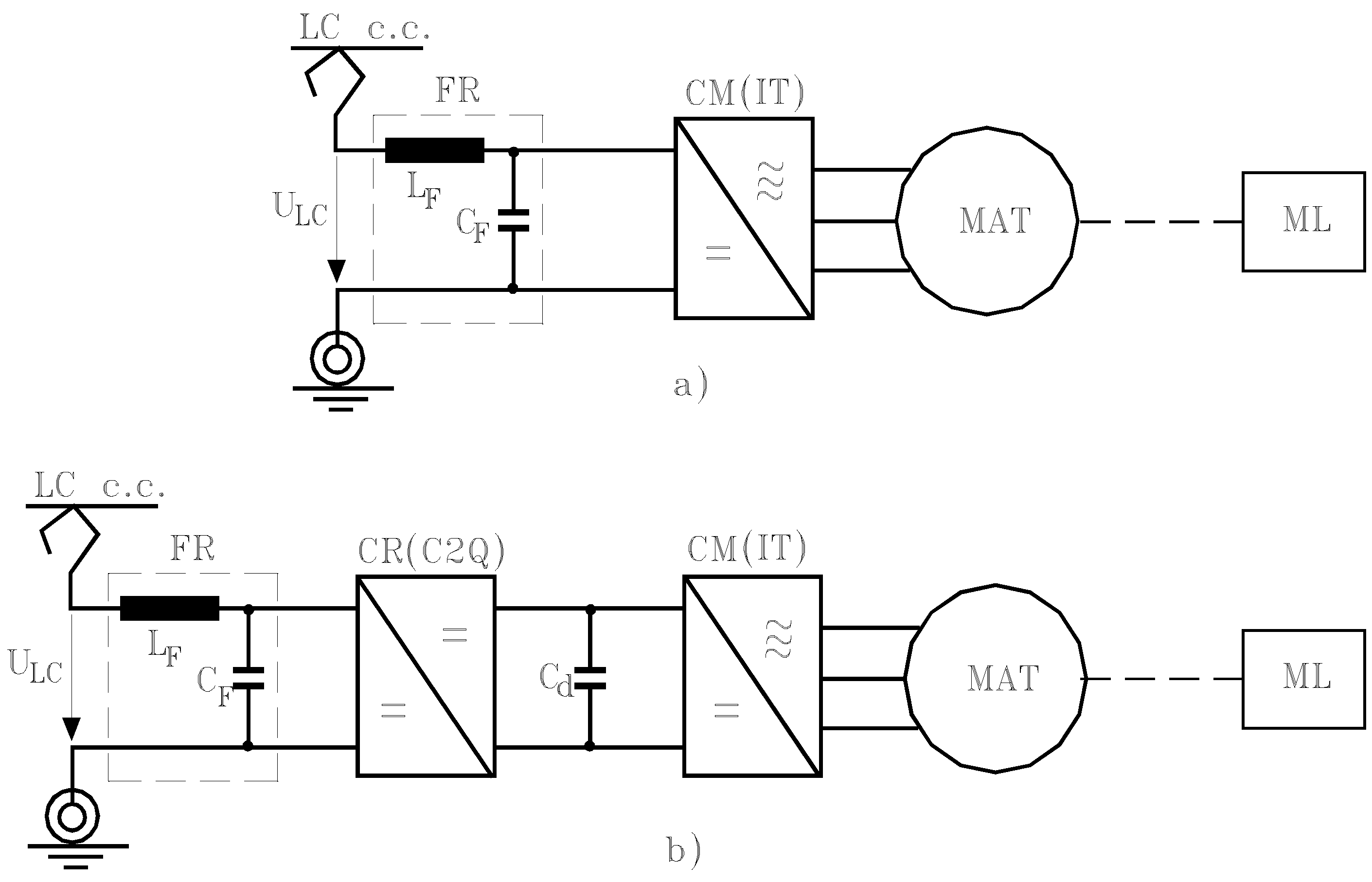
This supply type is achieved with a machine-side converter (CM), usually a VVVF inverter (IT) with two or three levels (
Figure 1). The working mechanism (ML) represents the mechanical part of the motor electric vehicle that it is located between a movement transformer (reduction gear) and a movement converter (wheel + rail) which transforms rotation into translational movement.
But, to commence, we need to know in what way electric traction drive systems based on static converters lead to an improvement in electric train performance, regarding both optimum traction characteristics (in terms of energy use) and high exergy efficiency in train operation, particularly for electric braking with energy recovery.
2.1. Operation at Variable Frequency of Induction Machine
An industrial ecosystem does not have a single equilibrium point [
19]. Rather, the system moves among multiple stable states [
20]. The dynamic regimes in electric train operation, e.g., starting or braking processes, can be viewed as representing the industrial ecosystem movement among points of equilibrium.
Figure 1.
Principal scheme of main electric circuits of urban electric trains fed by a d.c. contact line.
Figure 1.
Principal scheme of main electric circuits of urban electric trains fed by a d.c. contact line.
Vehicle regulation speed is determined examining the static converter (VVVF) and electric machine as an assembly [
21]. The traction motor speed regulation is based on stator voltage and frequency variation, so that to achieve high exergy efficiency, the first requirement of the train control system concerns passing of the motor operation equilibrium point from one mechanical characteristic to another.
In the range of frequencies lower than the rated frequency, fs < fN, in order to ensure a constant level of inductor machine stator flux Ψs = ΨsN, we have to simultaneously modify the frequency fs and the supply voltage magnitude Us so the supply r.m.s. voltage Us varies with the frequency fs according to Us(fs) = |RsIs + j2πfsΨSn|, where Rs is the stator resistance and Ψs the stator flux.
In the case considered subsequently of an induction machine supplied by a variable frequency voltage source, when the rated speed is reached (
i.e., the induction motor is supplied at U
N and f
N) a further increase in speed is possible only by increasing the stator frequency magnitude over the rated frequency f
s > f
N. Note that because of the voltage restriction on both converters and induction machine winding insulation considerations, the stator voltage is limited and maintained at a constant magnitude U
s = U
N for the entire high frequency domain, and the induction machine operates in weakened flux conditions [
17]. From an exergetic viewpoint it is noted that, because the stator flux and pulsation exhibit an inverse proportionality relation Ψ
s = U
N/ω
s, the machine torque capability is strongly affected, and the exergy destruction can not be avoided.
We conclude that the induction machine supplied from a variable frequency and voltage source operates with full field ψs = ψSn = const. in the low frequency range fs ≤ fN and with a weakened field (ψs < ψSn) in the increased frequency domain fs > fN (when the supply r.m.s. voltage remains constant (Us = UN = const.).
2.2. Electric Train with Induction Motors Operating at Variable Frequency and Controlled Flux
The operation at variable frequency with controlled flux is preceded for induction motors in drive systems with vectorial control [
22]. The vectorial regulation and control method is based on space phasor theory, taking into consideration the control of both the flux and the induction machine electromagnetic torque M. In principle, the stator current space phasor is decomposed into two perpendicular components (a flux component and a torque component) which are separately controlled. In this paper we analyze the steady-state sinusoidal regime of variable frequency operation with
controlled stator flux. Note that the theoretical developments presume an induction machine with constant parameters, without iron losses and without saturation of the magnetic core.
In the steady-state the following relations can be derived for the stator current components [
23]:
The absolute value of the stator current can be determined with the formula Is = (Isx2 + Isy2)1/2.
Within the ecological framework, the electromagnetic torque M is again related to the system output exergy. We can express M in complex coordinates axes system (oriented on
ψs) as
Substituting I
sy from (1), the torque relation becomes
If the stator flux ψ
s is constant, the electromagnetic torque magnitude depends on the rotor current pulsation ω
r but not the stator supply frequency f
s. The torque curve M = f(ω
r) at ψ
s = const. is not linearly dependent on ω
r, having two symmetrical extremes:
The dependence of M = f(ω
r) at ψ
s = const. is shown in
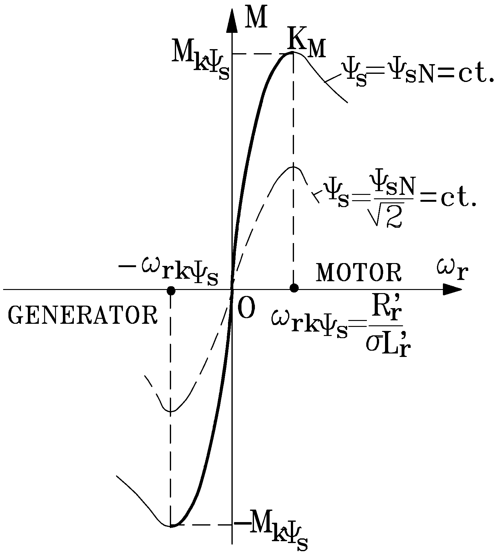
Figure 2.
In a steady-state regime, a system stable operation (with ∂M/∂ω
r > 0) is performed only on the ascendant zone of the characteristic M = f(ω
r) in
Figure 2 and corresponds at small rotor pulsations to the condition |ω
r| ≤ ω
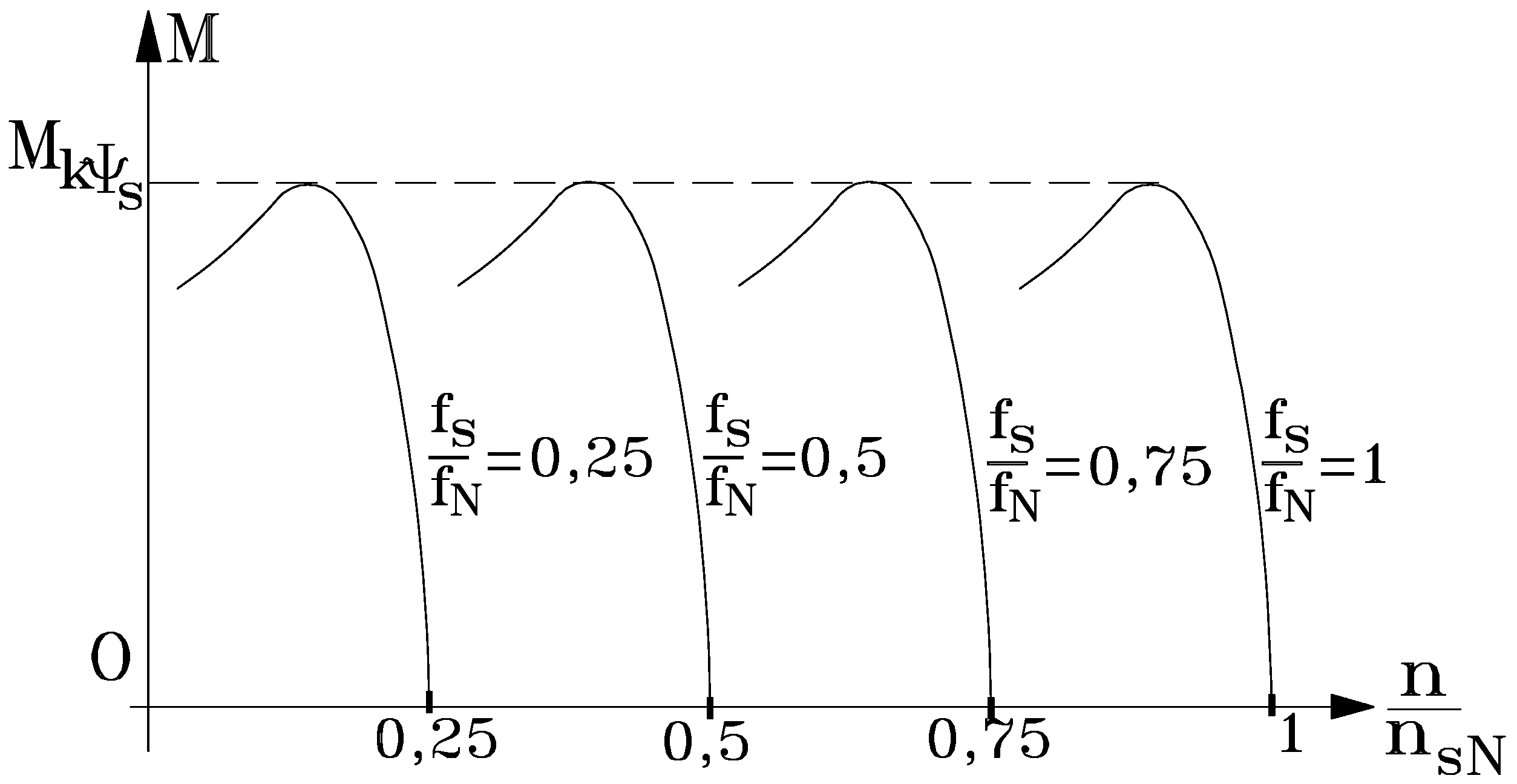
rkψs. The mechanical characteristics family M = f(n) of the induction motor operating at ψ
s = const., for different stator frequencies f
s are shown in
Figure 3.
Figure 2.
Torque characteristic M = f (ωr) at controlled stator flux.
Figure 2.
Torque characteristic M = f (ωr) at controlled stator flux.
Figure 3.
Mechanical characteristics M = f(n) at ψs = const. for different frequency values fs ≤ fN.
Figure 3.
Mechanical characteristics M = f(n) at ψs = const. for different frequency values fs ≤ fN.
The constant stator flux magnitude ψs for any stator frequency fs and torque M (respectively, any rotor pulsation ωr) imposes an exact control of either the supply voltage Us or the supply current Is. We see again an analogy between this electrical system and an ecosystem. An appropriate technical system control must be achieved for reducing exergy destruction when the equilibrium point passes from one stable state (represented by the operation point on a certain mechanical characteristic) to another stable state (on another mechanical characteristic). This observation implies the system control needs to be assessed next.
2.3. Modeling of Electric Train
Observations of nature suggest we need to identify modalities for optimum train control to minimize energy consumption and maximize exergy efficiency. We know the shape of the ideal traction characteristic [
17]. The real traction characteristic identifies if the train control is appropriate. To achieve vehicle control requires an analysis based on
structural diagrams.
First, we
model the traction induction motor, where electromechanical energy conversion occurs. As a complex electromechanical system, the induction motor can be conceptually decomposed into electromagnetic and mechanical subsystems. Between these functional parts, the electromagnetic torque M and the rotor mechanical speed Ω
m interact as internal variables. The induction motor electromagnetic part can be described by the following equations [
17]:
Here,
us denotes the stator voltage vector;
is the stator current vector;
ir’ the rotor current vector;
Ψs the stator flux vector;
Ψr’ the rotor flux vector; L
u the magnetizing inductance; L
s the stator inductance; L
r’ the rotor inductance; p the number of pole pairs; R
s the stator resistance; R
r’ the rotor resistance and
the motor leakage coefficient.
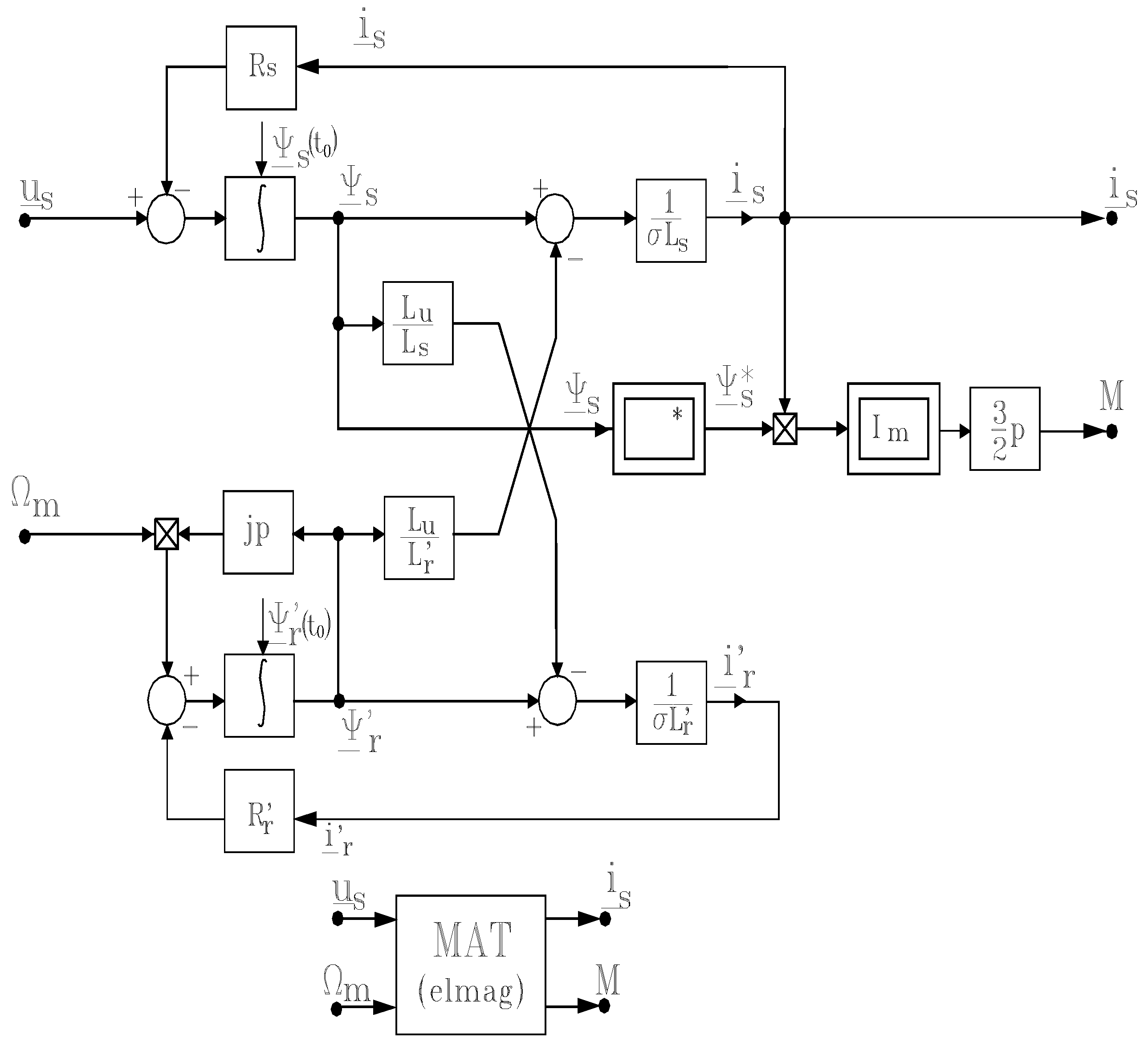
Using Equation (5), the structural diagram and the mask block of the induction motor electromagnetic part can be represented (
Figure 4).
Figure 4.
Structural diagram and mask block for induction motor electromagnetic part.
Figure 4.
Structural diagram and mask block for induction motor electromagnetic part.
The structural diagram of the electromagnetic subsystem can be coupled both with the structural diagram of the VVVF inverter through the input variable us and output variable is and with the structural diagram of the mechanical subsystem via the input quantity Ωm and the output quantity M.
To
model the machine-side converter, usually a voltage-source inverter, commutation functions are used in two or three levels, respectively [
17,
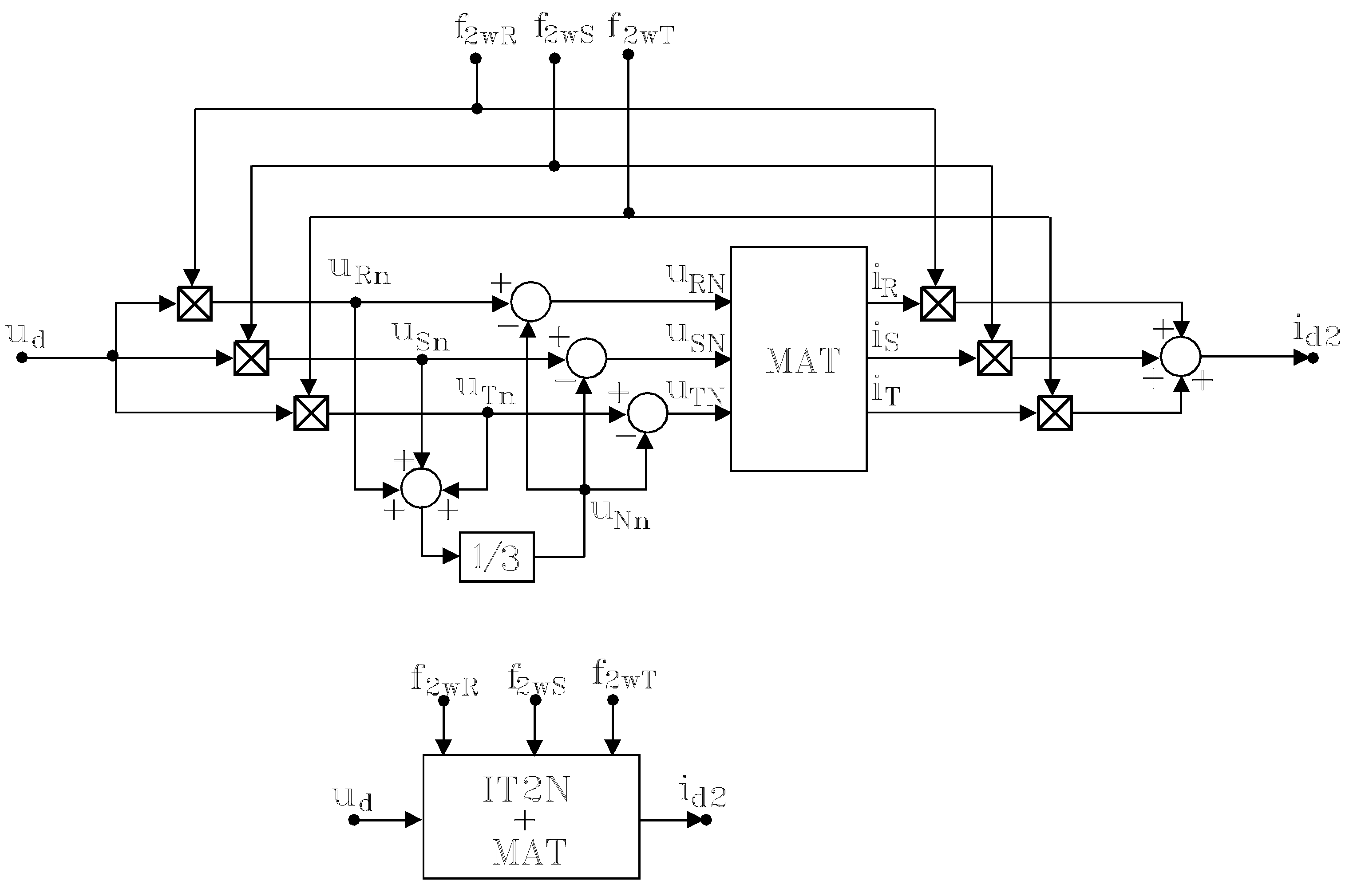
18]. A static converter can be viewed for modeling as a “black box” with input/output characteristics through the commutation functions. Analysing the topology of a three-phase voltage-source inverter with two levels and using the commutation function f
2w (in two levels),
, for each arm of converter, equations for the inverter model (without losses) can be written as:
With this system of equations, the structural diagram and mask block of the three-phase voltage-source inverter with two levels are obtained (
Figure 5).
Figure 5.
Structural diagram and mask block for three-phase voltage source inverter with two levels.
Figure 5.
Structural diagram and mask block for three-phase voltage source inverter with two levels.
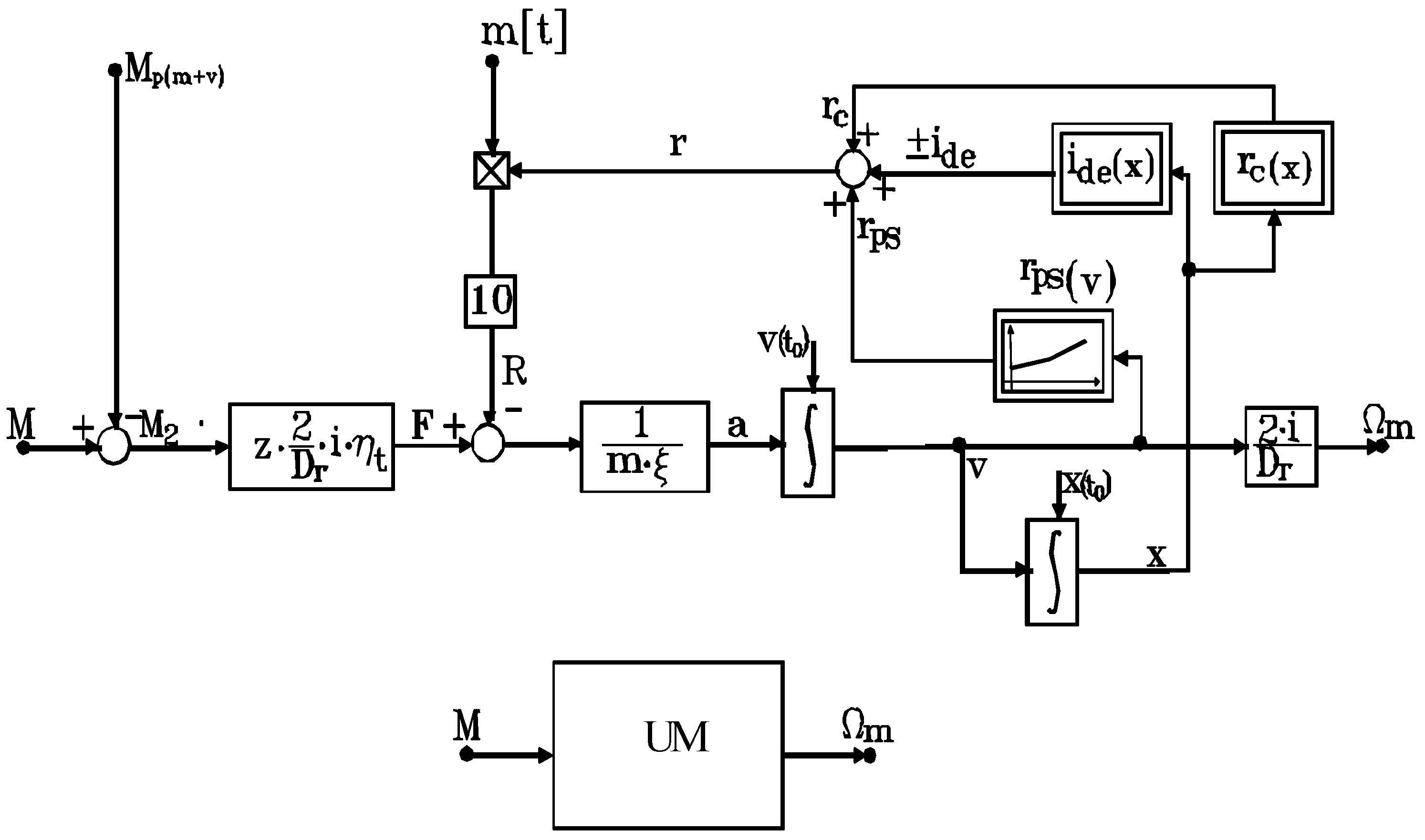
To highlight the exergetic dynamic approach of the system, a
vehicle useful movement model is also necessary [
17]. Here, we consider a motor electric vehicle with mass m[t] and inertia constant ξ having a specific train resistance r[daN/t]. If movement occurs due to the action of useful torques M
2 (identical), developed by z vehicle traction motors of the motor electric, then the useful movement can be described as:
which allow the construction of the structural diagram of useful movement (
Figure 6). For the mask block, we considered as an input quantity the torque M and as an output quantity the speed Ω
m,
i.e., the time-varying quantities during useful movement.
Figure 6.
Structural diagram and mask block of useful movement.
Figure 6.
Structural diagram and mask block of useful movement.
Subsequently, diagrams of train running speed v(t) and distance x(t) can be developed. Modifications to vehicle mass and dependences ide(x) or rc(x), specific to a vehicle or route, can be incorporated, yielding an exact model for all operating conditions.
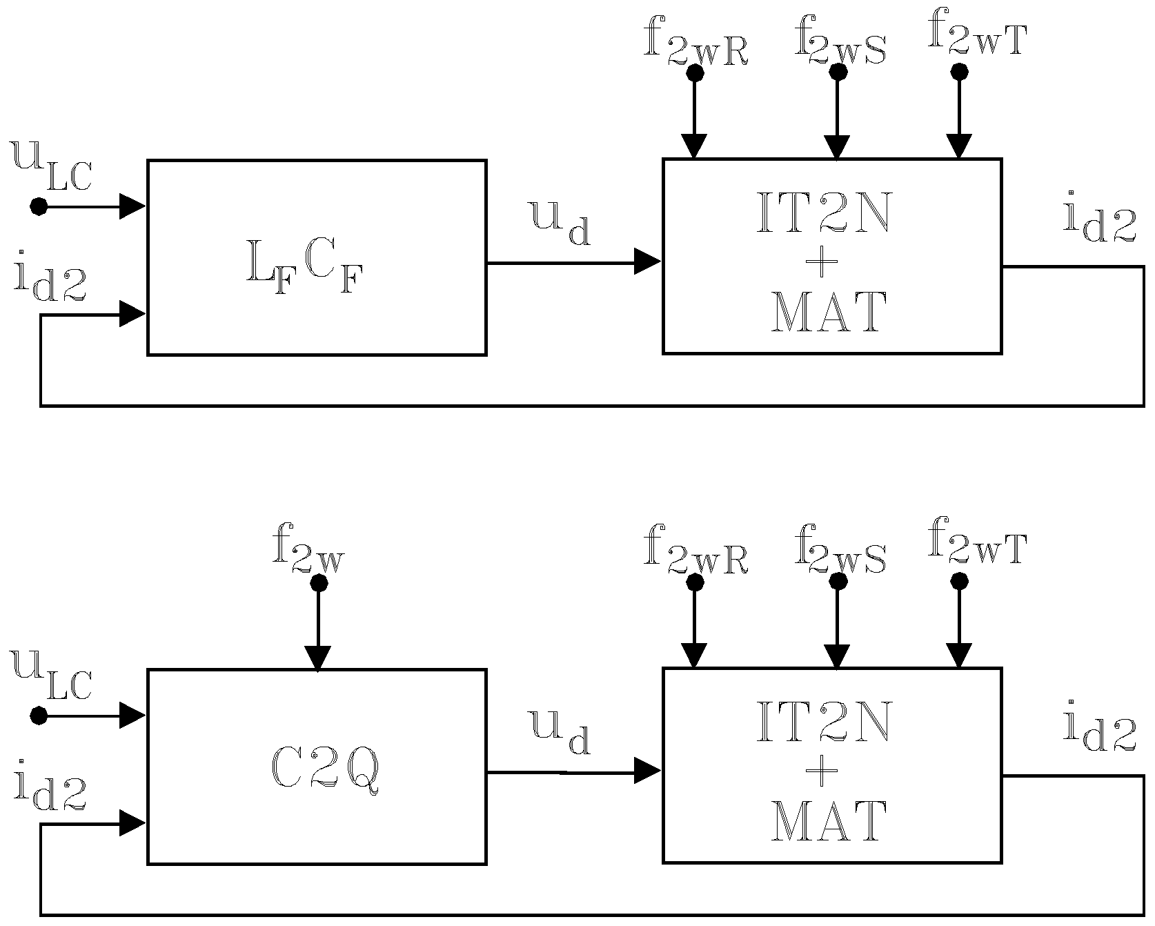
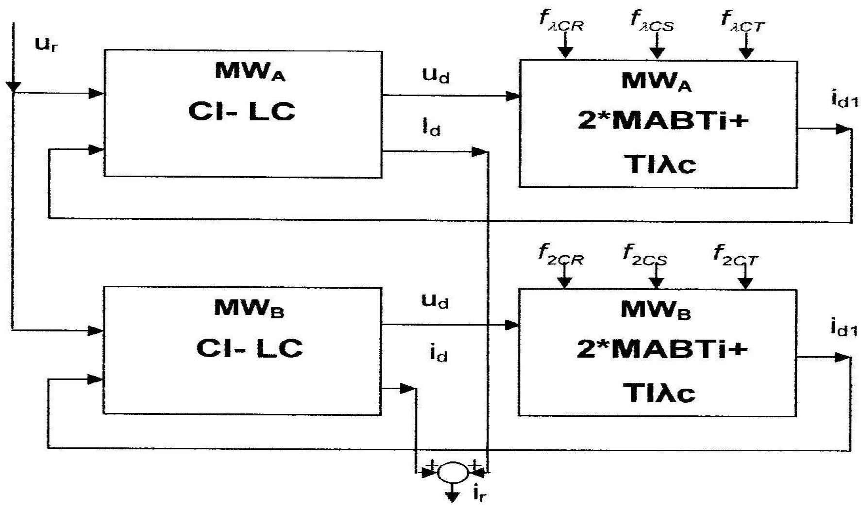
Figure 7.
Structural diagrams of main electric circuits.
Figure 7.
Structural diagrams of main electric circuits.
We began our study considering the main circuits of electric trains fed from a d.c. contact line (
Figure 1) and have obtained its structural diagrams (
Figure 7). This information supports the aim of optimizing vehicle control to obtain a high exergy efficiency.
3. Case Study
In this case study we consider an urban electric train with two motor wagons (MWs) which are elastic coupled and which are referred to as “MW + MW” [
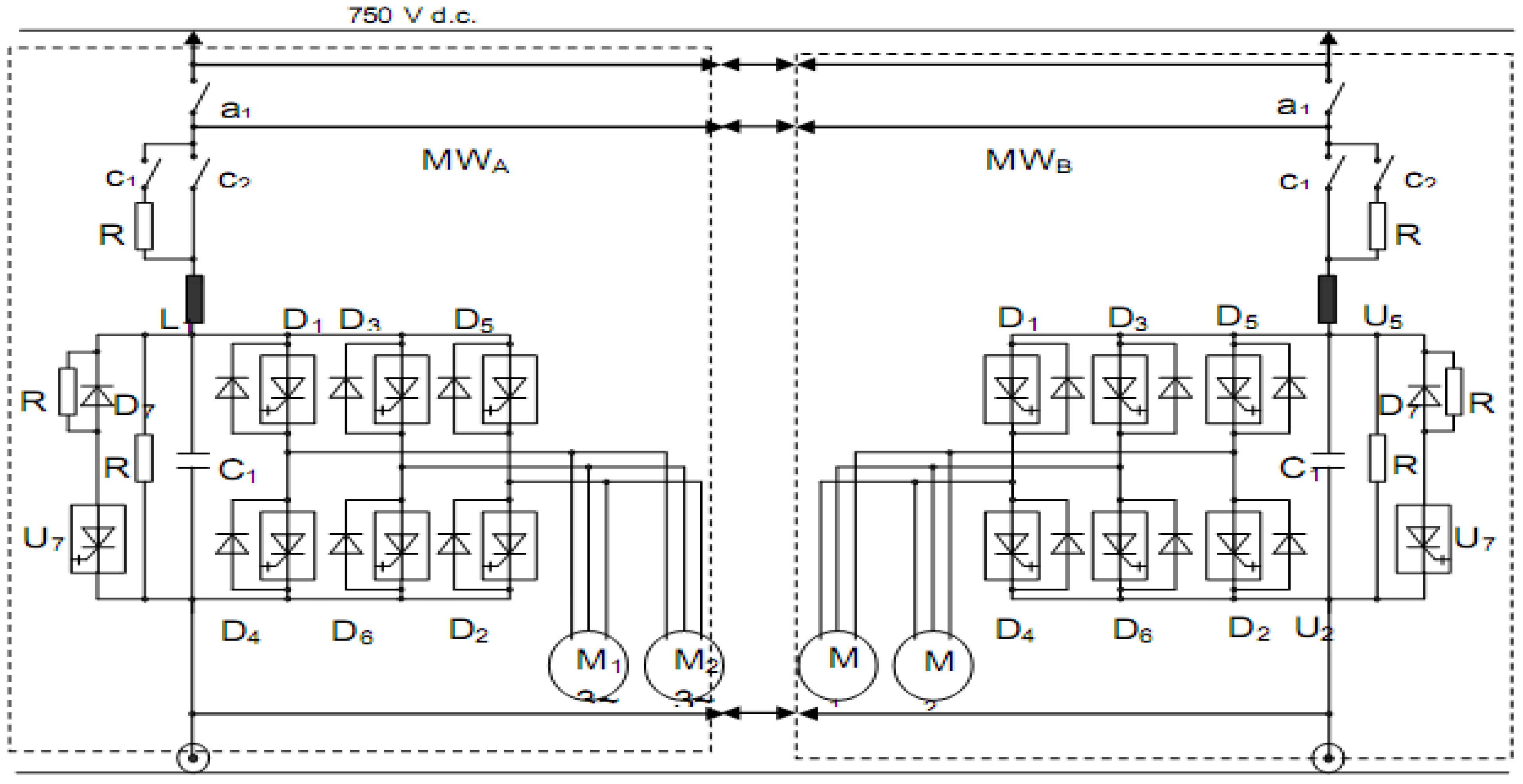
23]. The vehicle electric scheme (
Figure 8) is in variant V2, which is defined by the coefficient K = 2/2, indicating two static converters, each supplying two traction bi-motors. On the basis of the previous structural diagrams, the structural diagram for the urban electric vehicle viewed as a system is assessed in
Figure 9.
The electric traction scheme with a power supply from a d.c. network has the following elements [
17,
23]: a current connector to a third rail; a loading contactor and a loading resistor; a rapid automatic circuit breaker; an input circuit (known as a LC filter); a voltage and frequency converter; electric traction motors; a braking chopper and a braking resistor and a shunt; and electric couplings for the wagons.
From the technical point of view, the electric traction scheme presented here meets the criteria of vehicle operating safety and traction scheme reliability. An understanding of the sustainability of the electric transportation system can be obtained with an analysis of the exergy conversion chain within the electric transportation system operation regimes.
Figure 8.
Electric traction diagram in variant K = 2/2.
Figure 8.
Electric traction diagram in variant K = 2/2.
Figure 9.
Structural diagram of urban electric vehicle MW + MW, with K = 2/2.
Figure 9.
Structural diagram of urban electric vehicle MW + MW, with K = 2/2.
Here, the train operation is briefly described. After the connectors coupling, the circuit breakers and contactors switching, the control of the unit’s inverters is determined. The traction induction bi-motor groups are supplied from the three-phase VVVF inverters. Consequently, the urban electric train is able to operate. At the minimum adjusted frequency fmin = sfn. the traction motors M1 and M2 on the first unit MWA are immobile. Similarly M1 and M2 are placed on the second unit MWB.
When the frequency exceeds that value, the motors start to move, with the operation following the frequency mechanical characteristic corresponding to the minimum supply frequency. The electric train accelerates at a constant traction torque, with operation on the mechanical characteristics at up to fsn, when U1 = U1n and then, over fsn, at constant power.
The three-phase traction induction motors reverse their rotation via a simple supply commutation, by stator phases succession switching. The motors have identical characteristics for both rotation senses.
It is emphasized that
exergy issues prefer the vehicle electric motors operate at the designed rating power for a running speed range as long as possible [
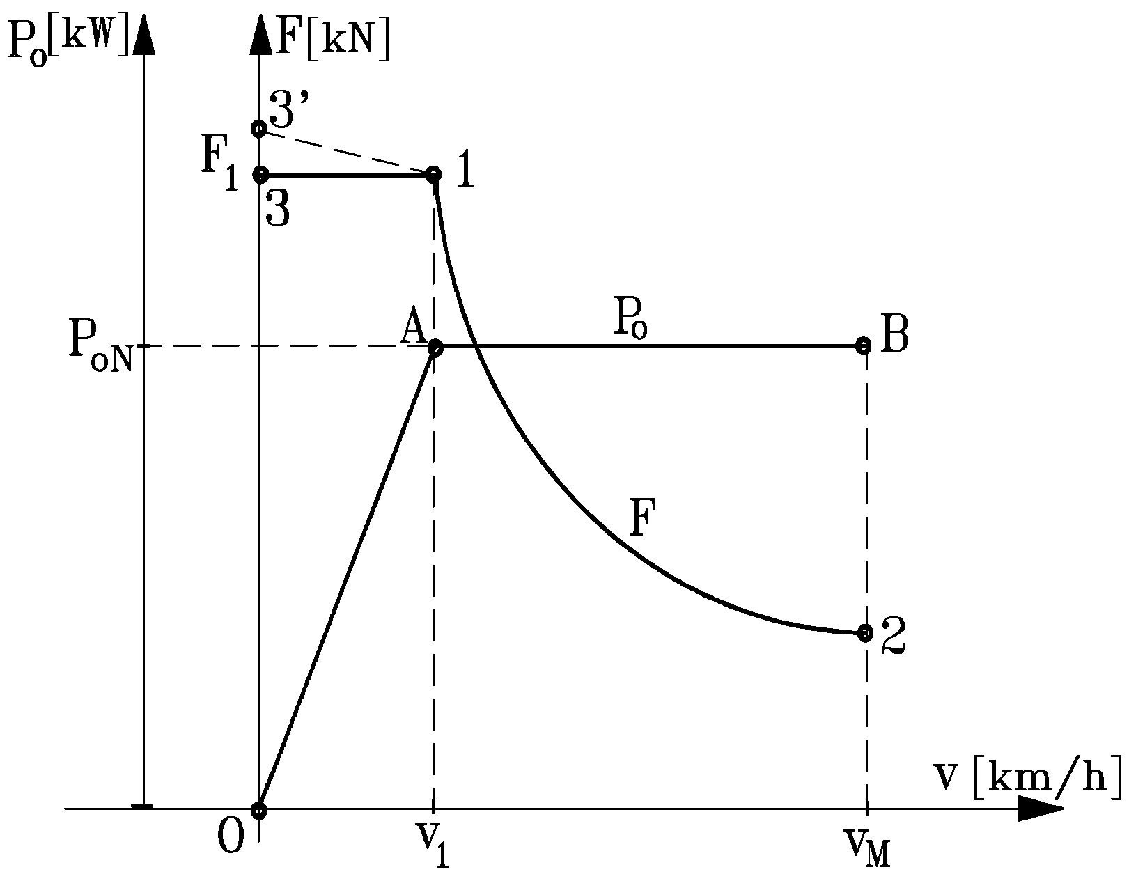
17]. Hence, the active power at rim P
0 is constant and the active force F depends on the speed according to
On basis of equation (8), a hyperbole form of the active force F results, as shown in
Figure10.
Figure 10.
Ideal mechanical characteristic.
Figure 10.
Ideal mechanical characteristic.
From the viewpoint of exergy efficiency and environment issues, a special aspect in case of the non-autonomous vehicles with electric traction is represented by the braking regime, particularly electric braking. Since electric driving systems with static converters and traction induction motors are used, electric braking with the same motors can be realized with appropriate control for electric traction vehicles. For a specified running direction, passing from the traction regime to the electric brake regime corresponds to a sign change of the active force F. Clearly in the traction regime the vehicle speed v and the active force F have the same sign, while in the braking regime v and F have opposite signs.
To perform electric train braking, the traction induction motors pass into the electric generator regime, by decreasing control of the supply voltage frequency. The electric traction machines operate in the generator regime on the mechanical characteristics M = f(n) in quadrants II and IV (
Figure 2 and
Figure 3), respectively. In that situation, which is complex from the viewpoint of power circulation, the inverter provides the reactive energy for the traction machine in the generator regime using the capacitor battery from the LC circuit and through the recovery diodes group, and the electrical machine supplies power like an induction generator into the d.c. network. This recovered energy is used by other operating trains. Thus the exergy efficiency is high. The d.c. network capacity to receive this electric energy is continuously checked by the vehicle control system. If the input circuit voltage exceeds 1.2U
d (
i.e., over 1.2 × 750 = 900 V), braking choppers are automatically activated, which realize an electric rheostatic brake regime. The braking resistances allow energy dissipation (by the Joule effect) of the uncirculated electric energy. Then, a high energy efficiency of the brake resistances is obtained, but the system exergy efficiency is significantly decreased.
The environmental impacts from the electric braking regime, particularly with recovered energy, by shifting the traction machines to an electric generator regime, are considerably reduced.
4. Experimental Results
The Bucharest Underground Railway System (METROREX) has trains equipped with traction induction motors MAB T
1, MAB T
2 and MAB T
3 produced by the Electroputere Factory in Craiova. The following railway vehicles types are considered:
urban electric train—heavy implementation REU-G with a weight of 36 t/wagon,
urban electric train—medium implementation REU-M, with a weight of 25 t/wagon, and
urban electric train—light implementation REU-U, with a weight of 15 t/wagon.
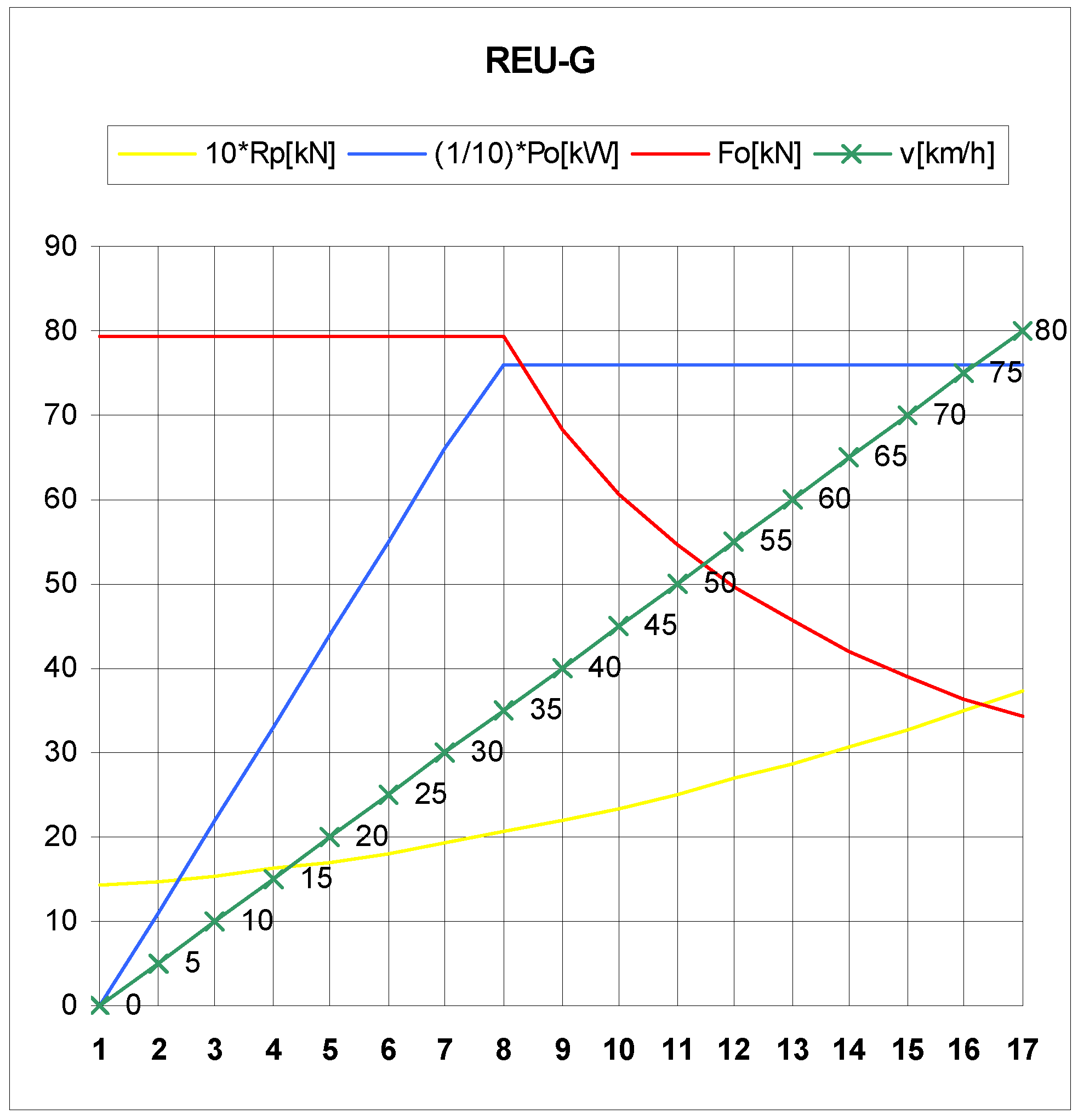
For REU-G, experimental traction characteristics are plotted in
Figure 11, showing the variations of characteristics are similar, suggesting
the goal of minimum energy consumption in the traction regime is accomplished. Data are provided in
Table 1.
Figure 11.
Variation of Rp, Po, Fo and v for REU-G.
Figure 11.
Variation of Rp, Po, Fo and v for REU-G.
Table 1.
Values of Rp, Po, Fo and v for REU-G.
Table 1.
Values of Rp, Po, Fo and v for REU-G.
| Rp [N] | Po [kW] | Fo [kN] | V [km/h] | Reading number |
|---|
| 1,419 | 0 | 79.27 | 0 | 1 |
| 1,474 | 110 | 79.27 | 5 | 2 |
| 1,539 | 220 | 79.27 | 10 | 3 |
| 1,617 | 330 | 79.27 | 15 | 4 |
| 1,709 | 440 | 79.27 | 20 | 5 |
| 1,812 | 550 | 79.27 | 25 | 6 |
| 1,926 | 661 | 79.27 | 30 | 7 |
| 2,053 | 760 | 79.27 | 35 | 8 |
| 2,194 | 760 | 68.37 | 40 | 9 |
| 2,344 | 760 | 60.77 | 45 | 10 |
| 2,508 | 760 | 54.70 | 50 | 11 |
| 2,684 | 760 | 49.72 | 55 | 12 |
| 2,872 | 760 | 45.60 | 60 | 13 |
| 3,070 | 760 | 42.07 | 65 | 14 |
| 3,281 | 760 | 39.07 | 70 | 15 |
| 3,506 | 760 | 36.46 | 75 | 16 |
| 3,743 | 760 | 34.18 | 80 | 17 |
Experimental electric braking characteristics for three train types REU-U, REU-M, REU-G used by the Bucharest Underground Railway System are presented in
Figure 12 and
Table 2.
Figure 12.
Variations of forces FF and speed v in electric braking regime for vehicles REU-U, REU-M, REU-G.
Figure 12.
Variations of forces FF and speed v in electric braking regime for vehicles REU-U, REU-M, REU-G.
Table 2.
Experimental electric braking characteristics for three train types.
Table 2.
Experimental electric braking characteristics for three train types.
| REU-U FF [kN] | REU-M FF [kN] | REU-G FF [kN] | V [km/h] | Reading number |
|---|
| 0.00 | 0.00 | 0.00 | 0 | 1 |
| 18.78 | 33.56 | 46.36 | 5 | 2 |
| 36.36 | 66.24 | 92.71 | 10 | 3 |
| 24.24 | 44.16 | 58.32 | 15 | 4 |
| 18.18 | 33.12 | 43.74 | 20 | 5 |
| 14.55 | 26.50 | 34.99 | 25 | 6 |
| 12.12 | 22.08 | 29.16 | 30 | 7 |
| 10.39 | 18.93 | 24.99 | 35 | 8 |
| 9.09 | 16.56 | 21.87 | 40 | 9 |
| 8.08 | 14.72 | 19.44 | 45 | 10 |
| 7.27 | 13.25 | 17.49 | 50 | 11 |
| 6.61 | 12.04 | 15.90 | 55 | 12 |
| 6.06 | 11.04 | 14.58 | 60 | 13 |
| 5.59 | 10.19 | 13.46 | 65 | 14 |
| 5.19 | 9.46 | 12.50 | 70 | 15 |
| 4.85 | 8.83 | 11.66 | 75 | 16 |
| 4.55 | 8.28 | 10.93 | 80 | 17 |
The Urban Underground Railway Transportation System in Bucharest is a network of four lines (M1, M2, M3 and M4) with 49 train stations and a total length of 67 km. Trains travel between 5 a.m. and 11:30 p.m., with an average frequency of 10 minutes.
In our calculations we assume the following:
a 1,560 m length between consecutive stations,
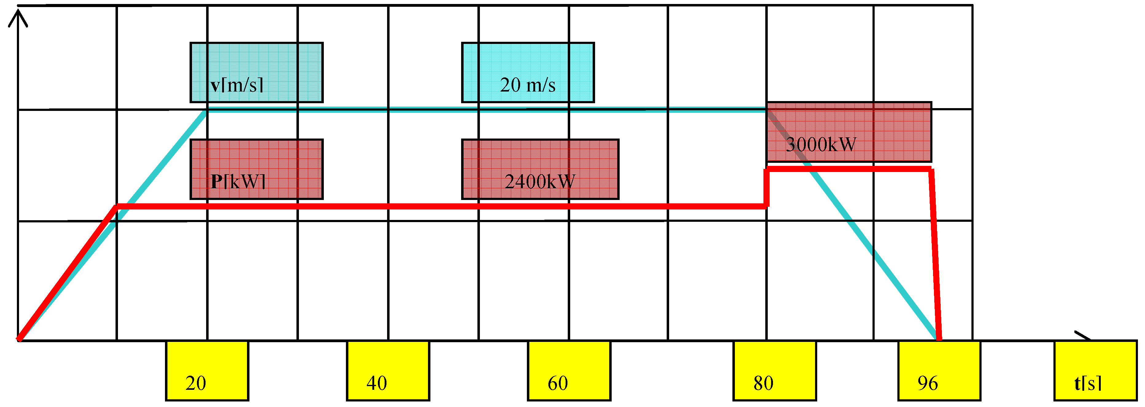
a running time between consecutive stations of 96 s, with 20 s transient starting (10 s at constant force and 10 s at constant power), 60 s of constant speed running and 16 s electric braking, and
electric active energies as in
Table 3, following the electric active power P values in
Figure 13.
During deceleration (interval 80–96 s), the electric active power (3,000 kW) corresponds to recovered energy or heat, depending on electric brake type.
An analysis of the recovered energy indicates that on a railway segment at least three trains must be in operation (two at speeds higher than 10 m/s and one in a uniform electric brake regime). So, for high exergy efficiency, the number of trains operating on a rail segment should be n = [3,000/2,400] × 2.
5. Discussion
The train case study considered yields particularly useful results in the traction regime. Using structural diagrams and high-performance converters, appropriate vehicle control can be achieved so the train experimental dynamic characteristics follow the theoretical mechanical characteristic. Then, the energy and exergy efficiencies are equal. Power converters and efficient anti-skid systems ensure optimum traction and minimum energy use.
Table 3.
Data for railway system.
Table 3.
Data for railway system.
| Parameter | Value |
|---|
| Railway length | 1,560 m |
| Cycle time | 96 s |
| Train number | 1 |
| Electric frames number | 3 |
| Number of wagons | 3 × 2 = 6 |
| Number of motors | 6 × 4 = 24 |
| Installed power, P | 2,400 kW |
| Running speed, vo | 20 m/s |
| Acceleration time, tac | 20 s |
| Uniform running time, tur | 60 s |
| Deceleration time, tdc | 16 s |
| Electric energy in acceleration regime, Eac | 36,000 kWs (10 kWh) |
| Electric energy in uniform running regime, Eur | 144,000 kWs (40 kWh) |
| Electric energy in deceleration regime, Edc | 48,000 kWs (13 kWh) |
Figure 13.
Variation with time of speed and supplied electric active power for a complete cycle: acceleration, constant speed running and deceleration.
Figure 13.
Variation with time of speed and supplied electric active power for a complete cycle: acceleration, constant speed running and deceleration.
Concerning train electric braking, further research is needed on the transportation system internal exergy consumptions. Actual techniques allow driving systems to be implemented on the basis of variable voltage and frequency static converters and induction motors, which facilitate improved electric braking, even with energy recovery. In that operating regime, the vehicle provides energy to the d.c. network through an inverter. The recovered energy is used by other underground trains, increasing exergy efficiency.
Another result related to exergy efficiency improvement relates to the railway transportation system traffic intensity and may seem paradoxical. At present, the energy recovered from electric braking can be provided only to running trains in the transportation system. As the number of running trains in the system increases, the exergy efficiency is high if the recovered electric energy is properly used. But with few running trains, if the third rail voltage exceeds 900 V, the rheostatic brake regime is automatically controlled and the recovered electric energy is transformed by the Joule Effect to heat. This is an unfavorable situation, with adequate energy efficiency, but a low exergy efficiency.
Electric braking with energy recovery should be compulsory in the long run in electric transportation systems to improve their sustainability, and the elasticity of reversible traction sub-station equipment should be taken into account.
The results are expected to help make electrical transportation systems more sustainable.
6. Conclusions
Energy systems involving conversion chain processes often are highly irreversible and have low exergy efficiencies. Within an Industrial Ecology framework there is great potential for improving the performance of such technical systems and increasing their sustainability. For instance, power converters and efficient anti-skid systems can ensure optimum traction with minimum electricity use, while energy can be recovered effectively via electric braking for use in other underground trains, increasing exergy efficiency. Further research is needed on the transportation system internal exergy efficiencies and consumptions related to train electric braking. Care must be exercised when implementing exergy efficiency improvements due to potential negative effects related to railway transportation system traffic intensity, which can lead to an adequate energy efficiency but a low exergy efficiency. Electric braking with energy recovery should be compulsory in the long run in electric transportation systems to improve their sustainability, and the elasticity of reversible traction sub-station equipment should be taken into account. If applied, the results of this investigation can help make electrical transportation systems more sustainable.
