Article

Experimental Study of Cement Mortar-Steel Fiber Reinforced Rammed Earth Wall

College of Civil Engineering and Architecture, Zhejiang University, Hangzhou 310058, China
*
Author to whom correspondence should be addressed.
Sustainability 2012, 4(10), 2630-2638; https://doi.org/10.3390/su4102630
Submission received: 16 July 2012 / Revised: 6 August 2012 / Accepted: 17 August 2012 / Published: 15 October 2012
(This article belongs to the Special Issue Hakka Tulou and Sustainability: The Greenest Buildings in the World)

Abstract

:
Rammed earth construction is an ancient technique which has recently attracted renewed interest throughout the world. Although rammed earth is currently regarded as a promising material in the construction industry in the context of sustainable development, it is difficult to quantify its bearing capacity, mechanical performance, as well as retrofitting approach, which discourages people from large-scale application in architectural engineering. This paper is devoted to the study of these problems based on rammed earth wall model experimentation. Three different models are studied considering different material components as well as structural configurations. By measuring the strain and deformation of the rammed earth wall models subjected to uniformly-distributed vertical loading, their ultimate bearing capacities are tested based on experimental investigation. Then the method of cement mortar-steel fiber reinforcement (CMSF) is carried out to study the ultimate bearing capacity enhancement of the wall models. Results show that the method of cement mortar-steel fiber reinforcement can increase the ultimate bearing capacity of the rammed earth wall models significantly, which is of relevant engineering significance in practical application.

1. Introduction

Along with the global climate deterioration, there have been long-lasting snow disasters and frozen rain in most parts of South China. Especially in 2008, such a snow storm and frozen rain disaster which had not occurred for the past 50 years severely affected tens of southern provinces to some extent, resulting in 107 casualties, 111.1 billion Yuan direct economic loss and the collapse of 354 thousand buildings. The major reason which led to such a large number of building collapse and damage was that the snow and frozen rain loads exceeded the structural ultimate bearing capacity. Many houses in rural areas of South China were built with traditional rammed earth, which gives rise to potential safety problems to the dwellings having relatively low compressive strength.
Rammed earth wall structure is one of the most widely used structural types in rural areas. Rammed earth is a kind of material usually composed of sand, soil and lime, the mixing proportion of which differs according to local customs. According to preliminary investigation, rammed earth walls in the countryside of South China are usually composed of sand (both fine and coarse sand), yellow mud and lime, while the mixing proportion is 3:1:0.6 (0.6–1) in mass. Rammed earth wall structure is a promising alternative to the widely used brick masonry structure due to its low-carbon property, convenient availability, good mechanical characteristics, and with it being economical. However, most existing structures of rammed earth wall have been used for decades, and their ultimate bearing capacities have declined, which lead to the disability to sustain infrequent heavy snow fall or frozen rain.
There have been corresponding studies and experiments on the rammed earth wall load-bearing structure. Xiong et al. [1] carried out experiments on river sand and lime compounded rammed earth block, including the compression test, shear test and bending test, and its failure characteristics and stress-strain relationship were proposed. Zhu et al. [2] studied the proportion of clay, lime, water and other aspects that may affect the compressive and shear strength. Huang et al. [3] analyzed the factors for adobe strength and proposed some suggestions and measurements to strengthen the adobe. In Bui’s work [4,5], rammed earth samples of three different scales (in-situ wall, representative volume element and compressed earth block) were studied. Based on the comparison of compression test results, the anisotropy of rammed earth was assessed. Maniatidis et al. [6] presented experimental results based on material and large-scale testing and developed a simple theoretical model. Kouakou et al. [7] studied the mechanical performances of rammed earth fabricated with soils containing argillaceous minerals as the sole binder, and found that the mechanical performances of adobes are dependent on the molding water content and the manufacturing process used. Jayasinghe et al. [8] studied the compressive strength characteristics of cement stabilized rammed earth walls and its relation to cement percentage. Reddy et al. [9] focused on the compaction characteristics and physical properties of compacted cement stabilized soil mixtures and cement stabilized rammed earth. Han et al. [10] used SV-II glue crack-pouring method to strengthen the back wall of Shuilu Temple in Xi’an, and the strengthening effect of this method was assessed. The construction process of contemporary stabilized rammed earth (SRE) utilizes modern equipment and portland cement as a stabilizer, which can create walls of very high strength and durability [11].
Studies correlated with retrofitting damaged rammed earth wall have been inadequate in the past. One approach is to fix external strengthening band on adobe walls, which showed excellent mechanical and seismic performance [12]. The application of the concrete code for rammed earth walls has resulted in the steel reinforcing schedules that closely resemble that of a concrete wall [11]. Other retrofitting approaches were not found in this field. The main contents of this study are to investigate the behavior and strengthening effect of the proposed cement mortar-steel fiber (CMSF) reinforcement method subjected to uniformly-distributed vertical loading. Three rammed earth wall models are fabricated based on the similarity principle, and the strengthening effect of the CMSF reinforcement method is assessed.

2. Model Test

2.1. Similarity Principle

Consider a practical rammed earth wall with the dimension of 4 meters in length, 3 meters in height, and 24 centimeters in thickness. The ultimate bearing capacity of the wall is formulated as
Sustainability 04 02630 i001
where F is the ultimate bearing capacity of the wall, σ is the ultimate compressive stress, W is the width of the wall, and t the thickness of the wall. Then the similarity principle in Equation 1 is formulated as
Sustainability 04 02630 i002
where
Sustainability 04 02630 i003
Variables with the subscript of “m” refer to the scaled model, while “p” represents the practical wall model. Substitute Equation 3 into Equation 2, the similarity relationship SF is obtained, which shows that the ultimate bearing capacity of the practical wall is two times that of the scaled model. It is noted that the boundary of the model wall is constrained by the concrete frame, and thus the similarity relationship in Equation 2 is still an approximation. However, the error caused by the similarity calculation is acceptable in engineering application.

2.2. Wall Model Designing

Three pieces of rammed earth walls were fabricated. The structural configuration of each wall model including component material proportion and structural dimension etc. is listed in Table 1. Three reinforced concrete frames were precasted to simulate the constraint of each wall boundaries. The general configuration of the experimental device of a rammed earth wall model is shown in Figure 1.
Table 1. Parameters of the walls (the proportion in the table is measured in mass).
WallsSand : Soil : LimeHeight × Width × ThicknessWindow Hole
W13 : 1 : 0.61,500 × 2,000 × 240 mm30
W23 : 1 : 0.61,500 × 2,000 × 240 mm31
W33 : 1 : 11,500 × 2,000 × 240 mm30

2.3. Reinforcement

The original three wall models (W1, W2 and W3) were loaded with the uniformly-distributed vertical loading in steps, and their ultimate bearing capacities were obtained. The results are shown in Table 2. After the first round of loading, cement mortar-steel fiber reinforcement was performed on the rammed earth walls. Steel webs of Φ4 in diameter with 300 mm-interval in both horizontal and vertical direction were fixed on the surface of each wall model. Tie bars went through the wall with an interval of 600 mm. Mortar of M10 (Chinese Masonry Design Code GB50003) was laid homogeneously on both sides of each wall with a thickness of 30 mm. The wall models W1, W2 and W3 after reinforcement, are labeled as W1’, W2’, and W3’, respectively.
Figure 1. General configuration of the experimental device.
Sustainability 04 02630 g001

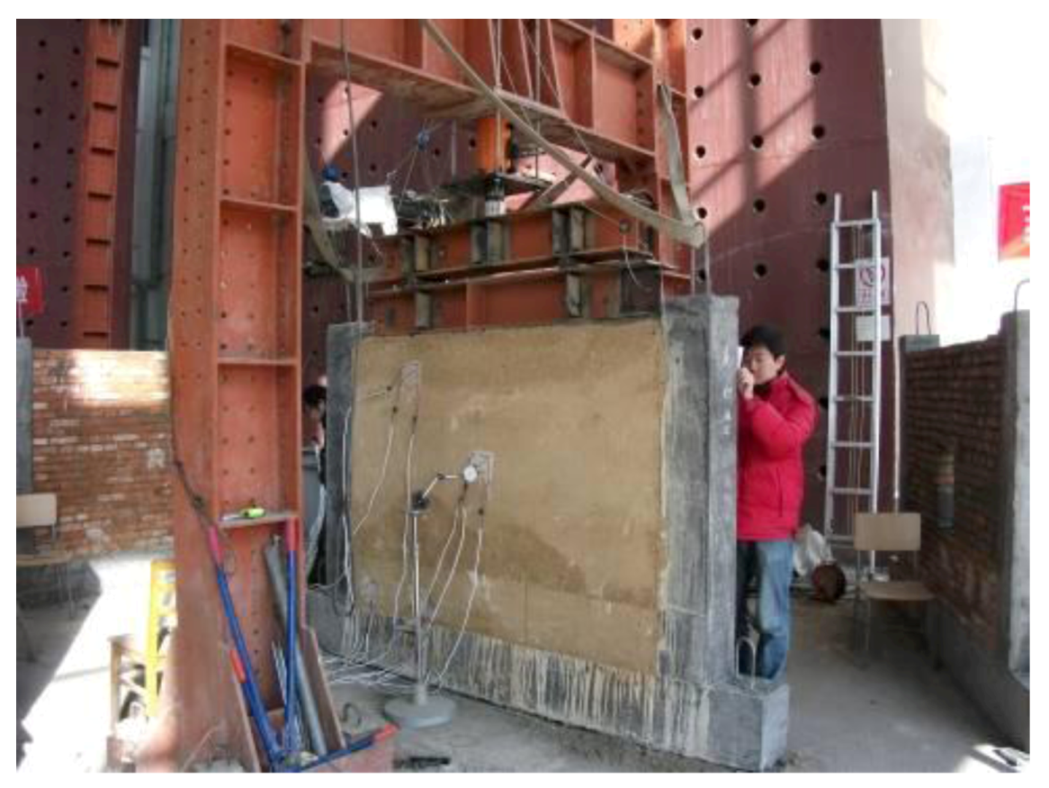
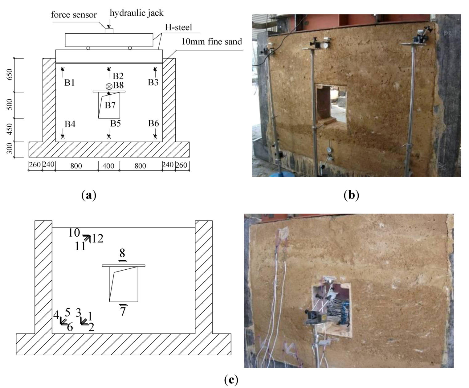
2.4. Loading and Data Collection

Vertical load generated by a hydraulic jack was delivered on top of the wall model through two stiffening-ribbed H-shaped steel beams. A force transducer was put between the jack and the upper H-steel. Fine sand was spread on the top of the wall homogenously to apply uniform vertical load approximately. Numerical simulations of the rammed earth wall models were carried out before the experiment to simulate the structural properties of the wall subjected to vertical loading. However, it is still difficult to estimate the ultimate bearing capacity of the wall models accurately due to various influencing factors as material discreteness. In consideration of the reason above, load from 5 to 20 kN in each step was applied gradually according to the structural response of the wall models. Each load step lasts for some time until the meter readings no longer change. Dial gauges were distributed at certain positions based on numerical simulation results to measure the strains in the middle and two sides of the wall model, as shown in Figure 2(a,b). The one perpendicular to the wall model (B8) was used to observe the out-of-plane displacement. Local strain of the wall was measured by strain rosettes which were distributed as shown in Figure 2(c).
Figure 2. (a) Loading system (B refers to dial gauge). (b) Dial gauges. (c) Distribution of Strain rosettes.
Sustainability 04 02630 g002

3. Results and Analysis

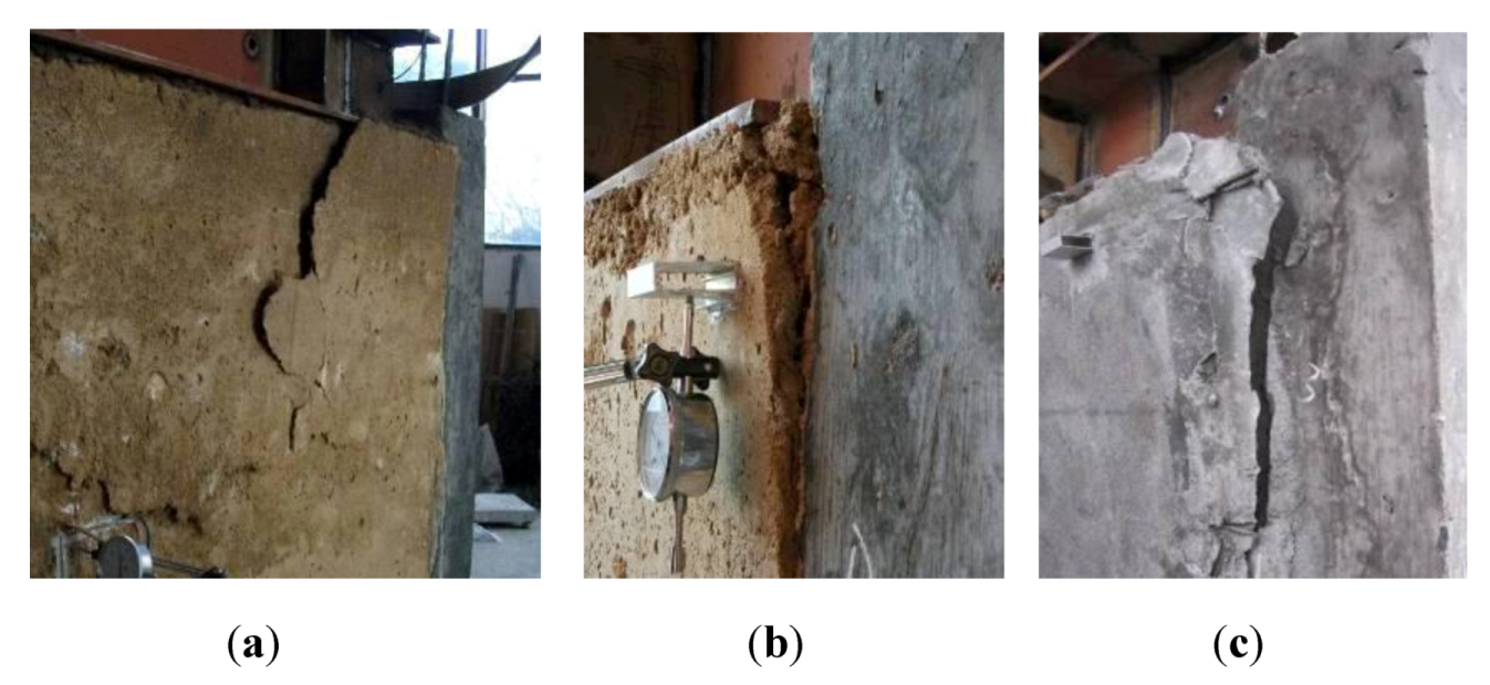
3.1. Failure Characteristics

It is noted that a rammed earth wall shows a behavior somewhat different to brick masonry. Brick masonry generally fails at much lower loads than brick compressive strengths due to interaction between the bricks and mortar. The absence of mortar joints makes the failure of rammed earth more of a crushing failure than a tensile failure. Therefore, a rammed earth wall may not give an adequate warning in the form of cracks. Hence, it is recommended to use an adequate factor of safety against failure in practical rammed wall structural application.
In this study of the three wall models, the W1 wall model suddenly cracked in the upper boundary when jack force reached 30 kN. The crack grew rapidly both in width and length, while a large part of the rammed earth on the corner was to drop down (Figure 3(a)). The W3 model, which contained more lime than W1, had swellings partially on the surface when the loading force reached 50 kN. Then cracks appeared on both sides of the upper corner. Applying load continually till 73 kN, the deformation increased rapidly, and then the wall model crashed at the loading of 90 kN, and the boundary of W3 separated from the RC frame (Figure 3(b)). The failure characteristics of W2 were almost the same as W3. After the first round of loading, the three wall models were reinforced using the aforesaid CMSF method, and similar experimental results were observed in the second round of loading, It is noted that the typical failure characteristics of the reinforced wall models was the separation of the mortar layers to the original rammed earth wall models (Figure 3(c)), and all the three models showed the cohesive failure of the rammed earth wall, while little failure was observed on the mortar layer.
Figure 3. (a) Failure of W1. (b) Failure of W3. (c) Failure of reinforced wall.
Sustainability 04 02630 g003

3.2. Test Results

Cracking load and ultimate bearing capacity of each wall model is shown in Table 2. From Table 2, it is noted that the method of cement mortar-steel fiber reinforcement enhances the strength of W1 and W2 greatly, while the enhancement of the wall W3 is not obvious, which is probably because the original ultimate bearing capacity of W3 is much greater than those of W1 and W2 since more lime is contained in W3. The strength of W1’ even reached about four times that of W1, and the ultimate bearing capacities of W2’ and W3’ are both greater than those of W2 and W3, respectively.
Table 2. Test results.
WallsCracking loadUltimate bearing capacityRise in ultimate bearing capacity
(kN)(kN)(%)
W13030-
W1’38112373%
W21336-
W2’80110306%
W35590-
W3’6994104%

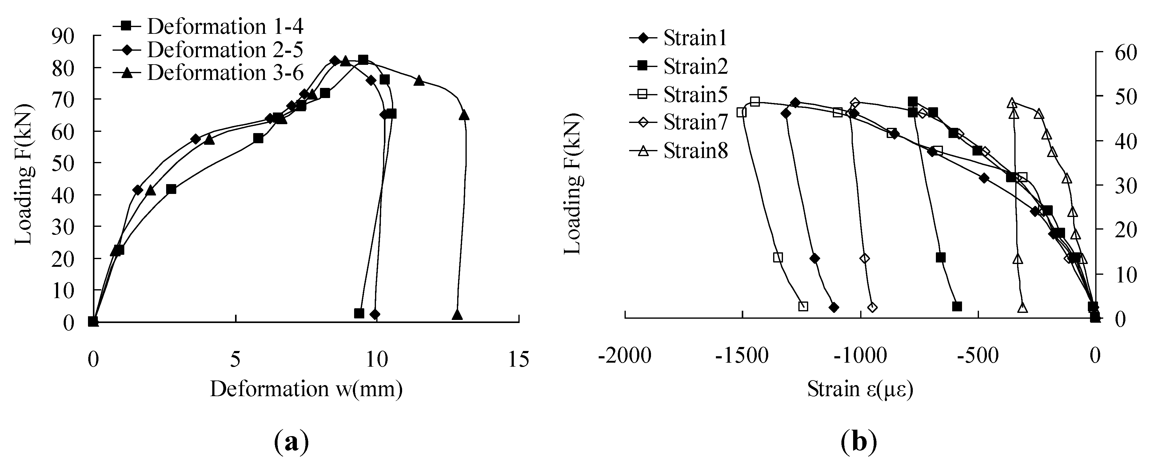
3.3. Strain and Deformation Analysis

Wall model W3 was taken as a typical example to investigate the deformation of the wall models. A loading-deformation curve (Figure 4(a)) was obtained based on the experimental results, which shows that the deformation increases with the increasing of the vertical force. From Figure 4(a), it is noted that in the plastic stage, the deformation of wall model W3 increases much even though loading increases little. When the load reached the peak point, it was gradually unloaded to zero. In this process, part of the elastic deformation recovered. However, loading track could not come back to the origin which obviously showed the elastoplasticity of the rammed earth wall.
A load-strain curve of W2 is shown in Figure 4(b) to investigate the plane strain of the wall models. All the strains increase with the loading. Different parts of the wall have different strains which indicate that the strain of the wall has become a 2-dimensional stress problem under the special boundary of RC frame. Strain 5 on the lower corner is greater than strains in other positions which indicate that arching above the window of W2 enhances the compressive strength of the whole wall by distributing the stress to the boundary on the two sides. Strain 7 and Strain 8 in Figure 4(b) illustrate that the rammed earth both above the window and below the window is in compressive status.
Figure 4. (a) Loading-Deformation Curve of W3. (b) Loading-Strain Curve of W2.
Sustainability 04 02630 g004

4. Conclusions

This paper presents an experimental study of cement mortar-steel fiber reinforcement and factors influencing the strength of rammed earth wall models. Results from three model tests are presented, and the effect of CMSF reinforcement method is investigated. The following conclusions are drawn as a result of this study:
  • Improving the mixing proportion of lime in the material can greatly improve the strength of rammed earth wall.
  • In this experiment, window hole does not influence the ultimate bearing capacity of the wall. On the contrary, the wall strength has increased a little. Arching effect may improve the compressive strength of the whole wall and distribute the stress to the boundary on two sides.
  • Cement mortar-steel fiber reinforcement can effectively enhance the ultimate bearing capacity of rammed earth wall.
  • All of the three reinforced walls failed because of the separation of mortar layer from the original wall due to rammed earth cohesive failure, while the mortar layer itself seldom cracked or destructed. This is probably due to the inner damage inside the rammed earth wall caused by the first round of loading, on which further study is expected to carry out comparative experimentation of the retrofitting effect using undamaged rammed earth wall models.

Acknowledgments

This study is a part of the research Project ‘Study of structural safety assessment and disaster prevention strategy of typical Zhejiang rural buildings subjected to snow and frozen rain load’, grant number Y1080556. The financial support of the Natural Science Foundation of Zhejiang province is greatly appreciated.

Conflict of Interest

The authors declare no conflict of interest.

References

  1. Xiong, B.; Hu, S. Analysis of strength and rupture of lime-soils. J. Sichuan Union Univ., Eng. Sci. Ed. 1997, 1, 63–67. [Google Scholar]
  2. Zhu, L.; Wang, Y. Study on the mechanical properties of non-adobe wall materials in the cold areas of Northern Xinjiang. J. Anhui Agr. Sci. 2008, 36, 15257–15258. [Google Scholar]
  3. Huang, J.; Tao, Z.; Lu, K.; Pan, W. Experiment on mechanics characteristics of adobe masonry of rural houses in Yunnan Province. Earthqu. Resist. Eng. Retrofitting 2008, 30, 94–98. [Google Scholar]
  4. Bui, Q.B.; Morel, J.C. Assessing the anisotropy of rammed earth. Construct. Build. Mater. 2009, 23, 3005–3011. [Google Scholar] [CrossRef]
  5. Bui, Q.B.; Jean, C.M.; Hans, S.; Meunier, N. Compression behavior of non-industrial materials in civil engineering by three scale experiments: The case of rammed earth. Mater. Struct. 2009, 42, 1101–1106. [Google Scholar] [CrossRef]
  6. Maniatidis, V.; Walker, P. Structure capacity of rammed earth in compression. J. Mater. Civil Eng. 2008, 20, 230–238. [Google Scholar] [CrossRef]
  7. Kouakou, C.H.; Morel, J.C. Strength and elasto-plastic properties of non-industrial building materials manufactured with clay as a natural binder. Appl. Clay Sci. 2009, 44, 27–34. [Google Scholar] [CrossRef]
  8. Jayasinghe, C.; Kamaladasa, N. Compressive strength characteristics of cement stabilized rammed earth walls. Construct. Building Mater. 2007, 21, 1971–1976. [Google Scholar] [CrossRef]
  9. Reddy, B.V.V.; Kumar, P.P. Cement stabilized rammed earth. Part A: Compaction characteristics and physical properties of compacted cement stabilized soils. Mater. Struct. 2010, 8, 681–693. [Google Scholar]
  10. Han, S.Y.; Wang, B.Q.; Xue, S.G. Analysis and reinforcement of adobe wall cracks. Shanxi Architect. 2007, 149, 15–18. [Google Scholar]
  11. Windstorm, B. A Report of Contemporary Rammed Earth Construction and Research in North America. In International Symposium on Innovation & Sustainability of Structures in Civil Engineering, Xiamen, China, 28–30 October 2011.
  12. Blondet, M.; Villa-Garcia, G.; Brzev, S. Earthquake-Resistant Construction of Adobe Building: A Tutorial; EERI/IAEE World Housing Encyclopedia: EERI, Oakland, CA, USA and IAEE: Tokyo, Japan, 2003. [Google Scholar]

