2.1. Calculation Conditions
For more precise designs, we developed an original CANDLE code system, adopting the 3D MCMG (based on Monte Carlo theory) transport method [
7] coupled with the thermal-hydraulic and neutronic interaction. This code system calculates the number densities of the nuclides, the neutron flux distributions, the Keff and the distributions of the thermal-hydraulic parameters in 3D cylindrical coordinates. The comparison between our previous 2D diffusion code and 3D transport code shows good consistency. Both the 2D and 3D calculations are applied to 21 neutron energy groups.
The 2D diffusion code uses the simple R-Z coordinates for the cylindrical core with few energy groups. The geometry meshes of this code are limited to the shapes of concentric cylinders. The calculation precision can be highly preserved if the core is homogeneously composed. The problem of proof of precision is encountered in a core design with engineering heterogeneity. Therefore, the 2D diffusion code is good enough for CANDLE burnup theory research and we developed the 3D diffusion and transport codes for the engineering core design, such as the MCMG code in the following. The 2D diffusion code has been estimated by IAEA, through the program “RBEC-M Depletion Benchmark Calculation, RCM of CRP i25001, IAEA”. The precision and reliability have been strictly checked.
The MCMG code is a 3D multigroup P3 Monte Carlo neutron transport code. It can treat complicated geometry like the hexagonal meshes of actual assemblies and has excellent variance reduction techniques. The number of energy groups in the MCMG code can be varied from a few groups to a multigroup (more than 100 groups), according to individual needs. Either macroscopic or microscopic cross sections can be used and its format is designed in accordance with the ANISN format. The MCMG code has been parallelized in the Parallel Virtual Machine (PVM) and the Message Passing Interface (MPI). The speedup increases linearly with the number of processors. Numerical tests show that the MCMG code can calculate the neutron transport problems accurately.
The current thermal-hydraulic calculation of the core adopted the Additional Heat Source method, in which the heat transfer between a fuel pin and the surrounding coolant is treated as an “additional heat source” in the calculation of the fuel pin temperature distribution. By this method, the temperature field and flow field in the core region are implicitly integrated and solved through iterations. The thermal-hydraulic calculation considers the axial and radial heat conductions in the fuel cell, the heat conduction between the fuel cell and the cladding through the liquid metal bond, and the heat transfer between the cladding and coolant. The newly introduced fuel cell axial heat conduction calculation contributes to more precise results for the thermal estimation and the feedback for microscopic cross sections, since the fuel cells have large diameters and sharp axial temperature gradients in a CANDLE core.
The SRAC2006 code [
8] was adopted to generate the microscopic cross section library, which has 96 sets used for interpolation, according to the change of temperature field and burnup depth. This library is based on the major neutron data library SRACLIB-JDL33. The U4cm466fp burnup chain and the th2cm6fp50bp16F burnup chain are applied to the 1000 MWth case and the 2000 MWth case, respectively.
2.2. The Design and Results of the 1000 MWth CANDLE Reactor
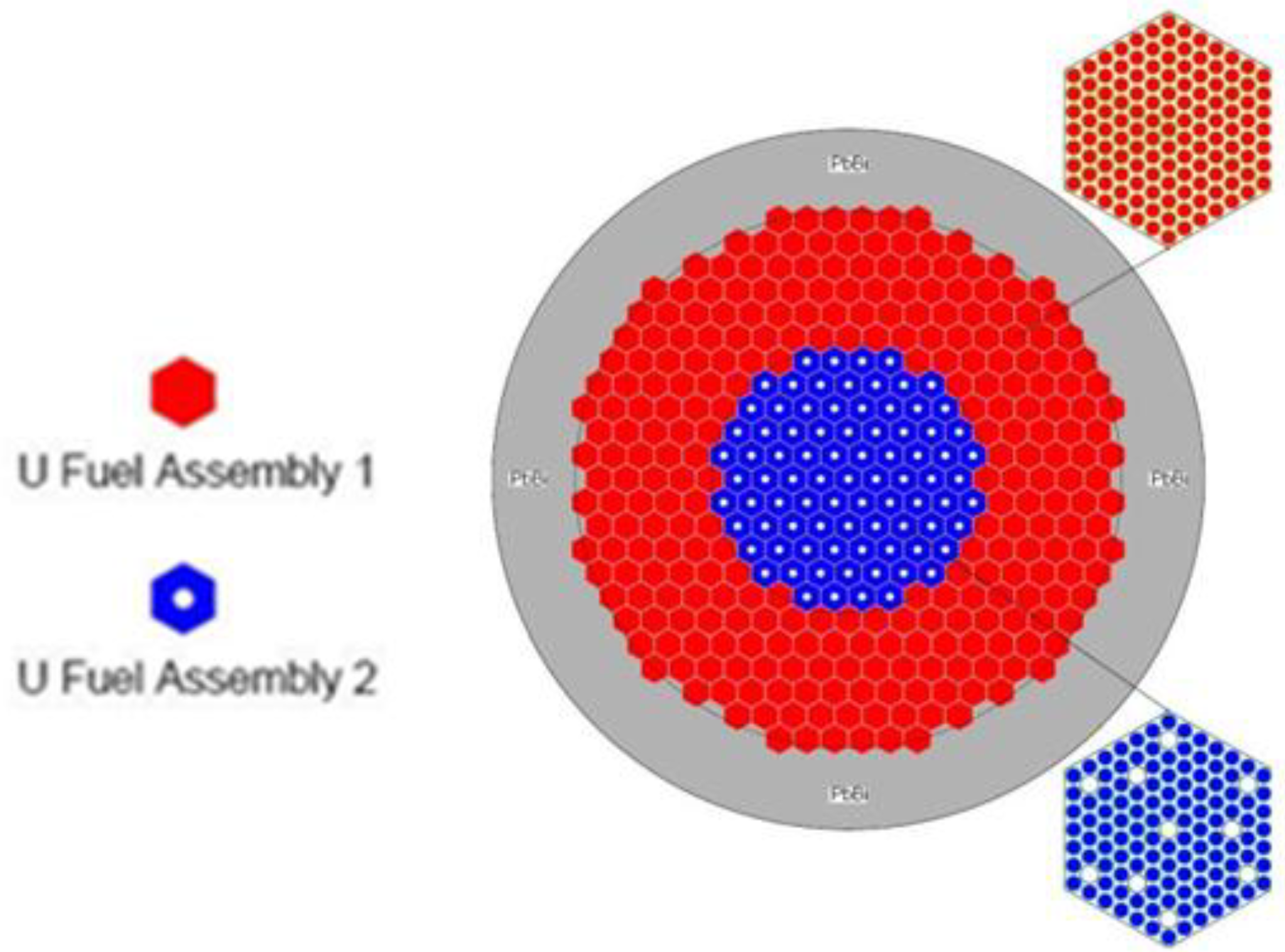
The inner region is composed of type 2 fuel assemblies, while the outer region is filled with type 1 fuel assemblies, surrounded by a 50 cm thick LBE reflector. Each assembly of the outer region is made up of the triangularly assembled cylindrical fuel pins with a U235 enrichment of 2.7%. Each assembly in the inner region has an empty space ratio of 7.87%, which can be utilized for the channels of the shutdown control rod assemblies and the experimental/detective equipment. The empty channels are uniformly scattered in every inner core assembly for easier simulation and will be gathered into specific units in each case. N15 enriched nitride natural uranium is the fuel used in the inner region. The main design parameters are shown in
Table 1.
Table 1.
The 1000 MWth CANDLE core design parameters.
Table 1.
The 1000 MWth CANDLE core design parameters.
| Main Design Parameters | Values/Specifications |
|---|
| Thermal Power/MWth | 1000 |
| Core Height/cm | 230 |
| Core Radius/cm | 165 |
| Radius of Inner Core/cm | 82.5 |
| Thickness of Reflector/cm | 50 |
| Fuel Cell Radius/mm | 6 |
| Thickness of Cladding/mm | 0.5 |
| Distance between fuel pins/mm | 0.8 |
| Fuel Material of Inner Core | Natural UN |
| Fuel Material of Outer Core | Enrichment 2.7% UN |
| Cladding Material | HT-9 |
| Coolant Material | LBE (44.5%–55.5%) |
| Reflector Material | LBE (44.5%–55.5%) |
| Core Inlet Temp/K | 600 |
| Core Outlet Temp Peak/K | 800 |
The 1000 MWth power level is the preferred choice for places with middle energy demands, such as the western cities of China which are spread over a large area and lack water. For an easier engineering approach, we adopted the conventional cylindrical fuel pins with a relatively large pellet diameter, instead of the tube-in-shell type with hexagonal surface adopted in the previous design of the small long life CANDLE reactor [
2]. As a result, the fuel volume ratio of the present design cannot be increased as much as in the previous one. The size of the core is increased and the fuel in the outer region is mildly enriched. The optimized radial power distribution enables a high average enthalpy of the outlet coolant with a large safety margin. The N15 enriched uranium is used as fresh fuel. This application takes pressure off the need for mining and processing, while greatly reducing the generation of C14 from N14 through the (n, p) reaction. Further, the extremely high melting point of the nitride fuel improves the core safety. F/M stainless steel HT-9 is chosen for the cladding material due to its good ability to maintain integrity in the LBE coolant and the long life expectancy. The coolant inlet temperature and the maximum outlet temperature are set at 600 K and 800 K, respectively. This temperature range is suitable for the integrity of core materials while allowing economically efficient energy production. Also, large margins are permitted within the temperature limits and the safety of the core can be assured in case of accidents.
The key results are shown in
Table 2.
Table 2.
The key results of the 1000 MWth CANDLE reactor design.
Table 2.
The key results of the 1000 MWth CANDLE reactor design.
| Key Results | Values |
|---|
| Keff | 1.0018 |
| Burnup Velocity/cm/year | 1.59 |
| Max Burnup Depth/% | 57.0 |
| Fuel Cell Temp Peak/K | 883.4 |
| Cladding Temp Peak/K | 801.2 |
| Maximum Coolant Velocity/m/s | 2.2 |
With the present design, the Keff can be very close to unity and the little discrepancy of 1.8e-3 would be easily corrected with the reactivity feedback in actual performance. The burnup velocity of 1.59 cm/year gives a core life of more than 50 years without reactivity fluctuation, according to the core height value. If we ignore the material problems here, this core can be regarded as a nuclear battery, which generates the energy very stably without burnup control and needs no refueling. The high burnup ratio is a merit and a challenge at the same time. The core can burn almost half of the loaded fertile materials in one life, greatly improving the utilization capability of the nuclear resources. On the other hand, no known material can survive this high burnup and last until the end of the core life. Ensuring the integrity of the cladding material would not pose any risk in the long run, and new materials and measures are under investigation. The temperature peaks of the fuel pellet and the cladding are quite low compared with their corresponding temperature limits.
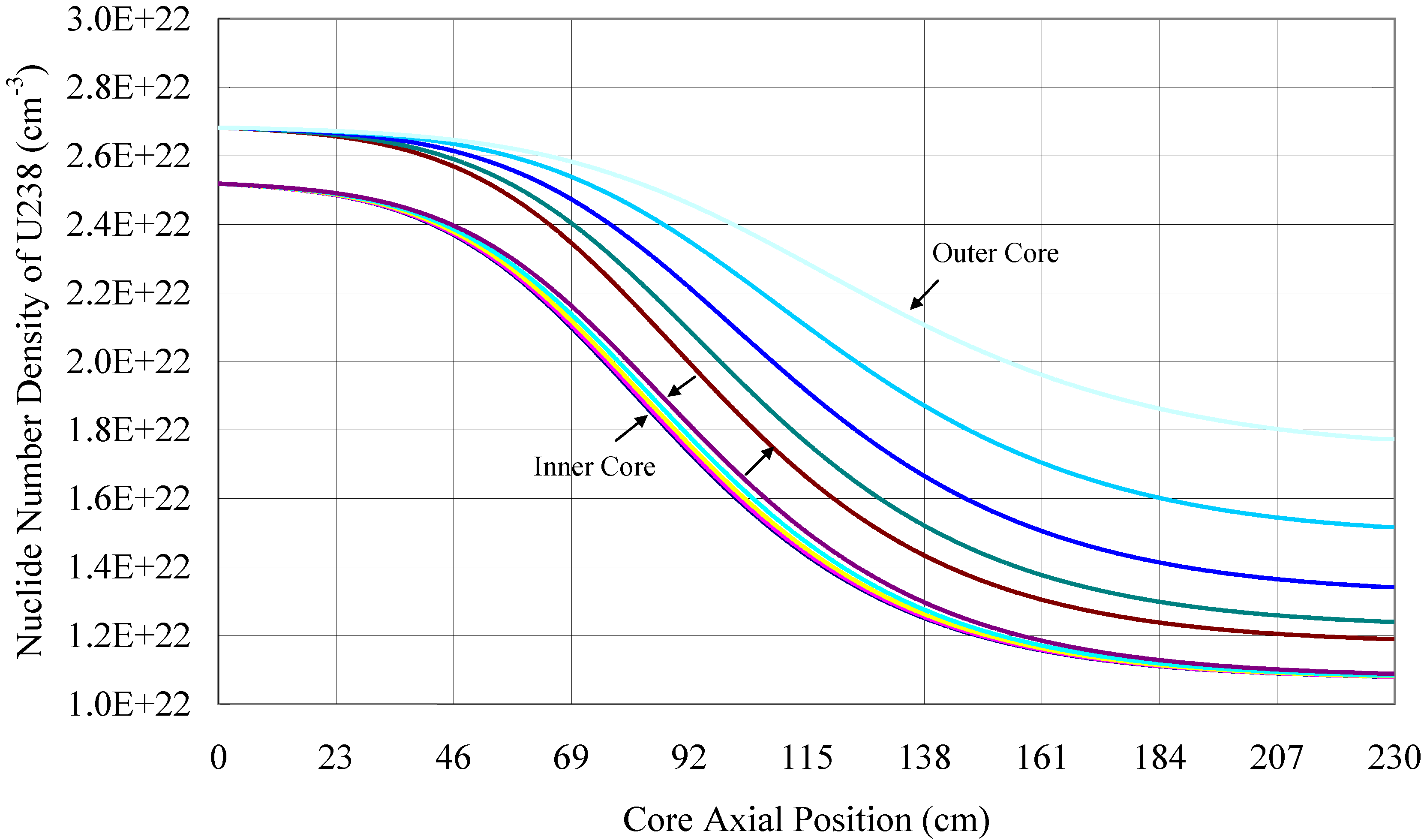
Figure 2 and
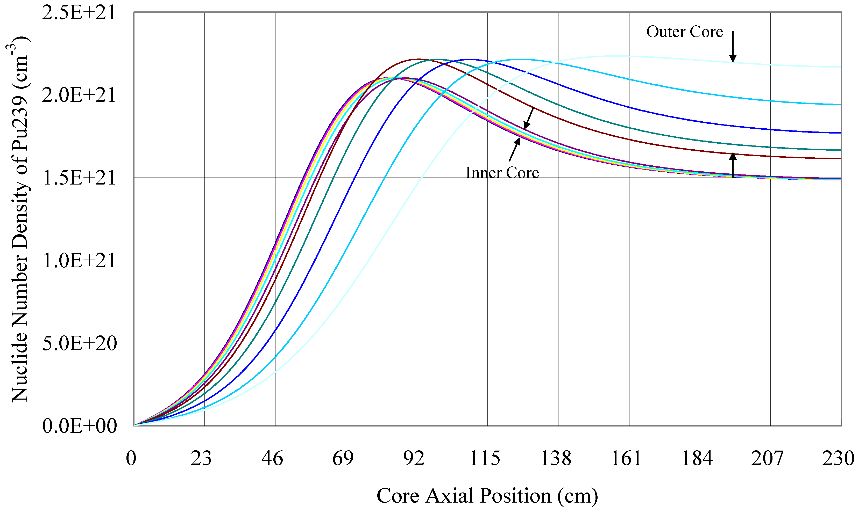
Figure 3 present the equilibrium number density distributions of nuclide U238 and Pu239, respectively. The core is divided into 10 equidistant circles in the radial direction. Every line in the two figures presents the number density information of every circle. We put the 10 circles into two groups, representing the inner core region and outer core region, respectively, to show the effect of the design. The curves located in the inner region and outer region are marked by pairs of arrows. The number density of the nuclides in the inner region is volume weighted, since there are empty channels in the assemblies. These two figures reveal that the fuel conversion and burnup ratios of this core are rather high. The nuclide number density distributions of the different radial rings in the inner core almost overlap each other. This reflects that the burnup is uniform in the different radial circles, which would generate a flat neutron flux distribution. The core utilizes the fertile nuclides very efficiently, while on the other hand, posing a challenge to the core materials.
Figure 2.
The equilibrium nuclide number density distribution of U238.
Figure 2.
The equilibrium nuclide number density distribution of U238.
Figure 3.
The equilibrium nuclide number density distribution of Pu239.
Figure 3.
The equilibrium nuclide number density distribution of Pu239.
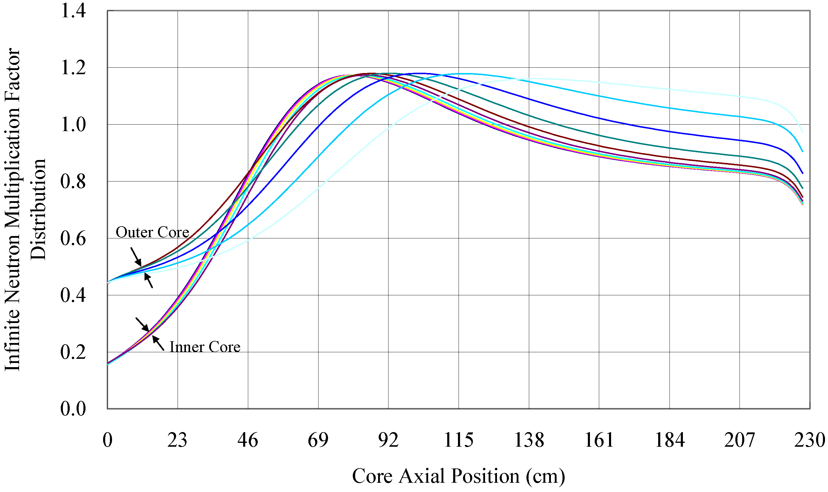
Figure 4 shows the infinite neutron multiplication factor distribution (Kinf). It is mainly dominated by the number density distribution of the Pu239 transmuted from U238 and it clearly divides the core axis into the fresh fuel region, the burning region and the spent fuel region, according to the factor values. On the left side of
Figure 4 (fresh fuel region), the factor of the outer region is higher than that of the inner region, because the outer region is enriched to a low level.
Figure 4.
The infinite neutron multiplication factor distribution.
Figure 4.
The infinite neutron multiplication factor distribution.
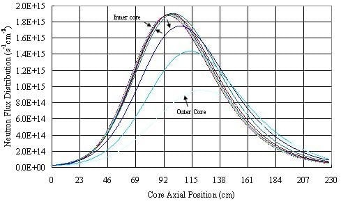
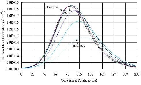
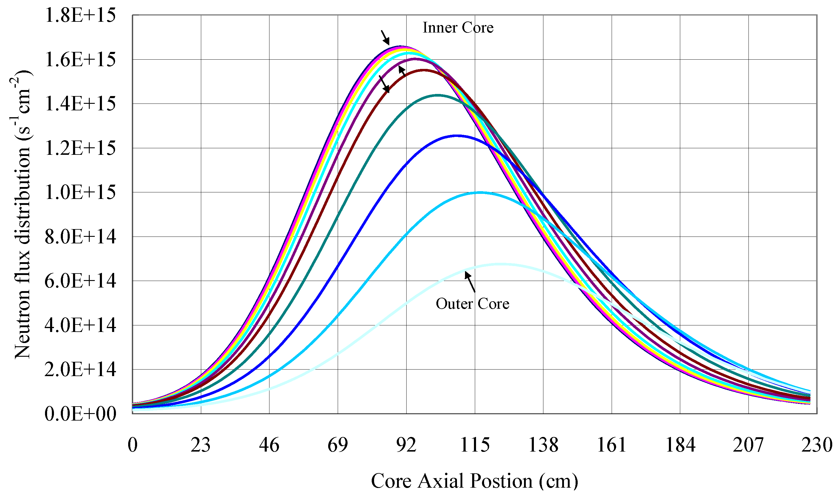
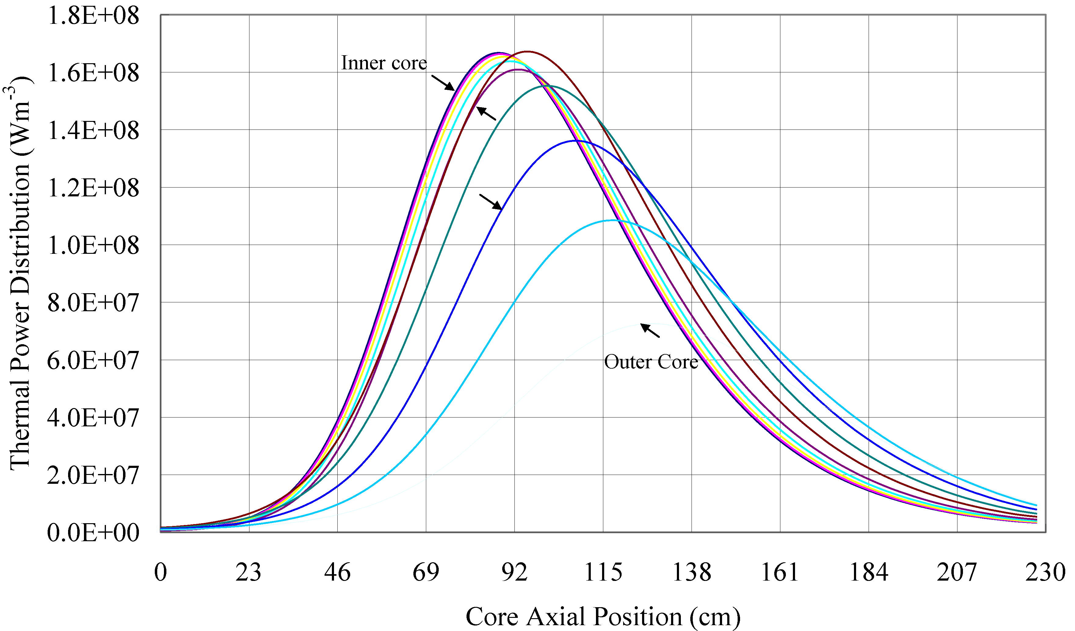
Figure 5 and
Figure 6 show that the radial neutron flux distribution and radial thermal power distribution were successfully flattened. The inner region is covered by a very flat distribution, as shown in the 3D figures of
Figure 7. In the axial direction of the core, on each axial layer of the burning region, 25% of the area is covered by the same flux level. Also, more than 72% of the area is covered by the neutron flux,
i.e. between 1.65e15 cm
−2s
−1 to 1.0e15 cm
−2s
−1 at the axial flux peak. According to
Figure 5, the burning region materials that are exposed to the highest flux radiation would take about 18.8 years to reach the damage neutron fluence limit, which is about 250 dpa (5.0e23 cm
−2) [
9], from new. The counted neutron flux has an energy level higher than 0.1 MeV, which is about 50% of the summation for the present case. In other words, after every performance period of 18.8 years, proper measures such as the “recladding procedure” [
10] should be carried out. In such a procedure, all of the fuel pins would be entirely recladded for the longest performance periods. Meanwhile, the spent fuel would be removed and fresh fuel would be added at the two axial core ends, respectively. After this procedure, the state of the core will be rejuvenated and the new operation period will repeat the burnup process of the previous 18.8 years.
Figure 5.
The neutron flux distribution.
Figure 5.
The neutron flux distribution.
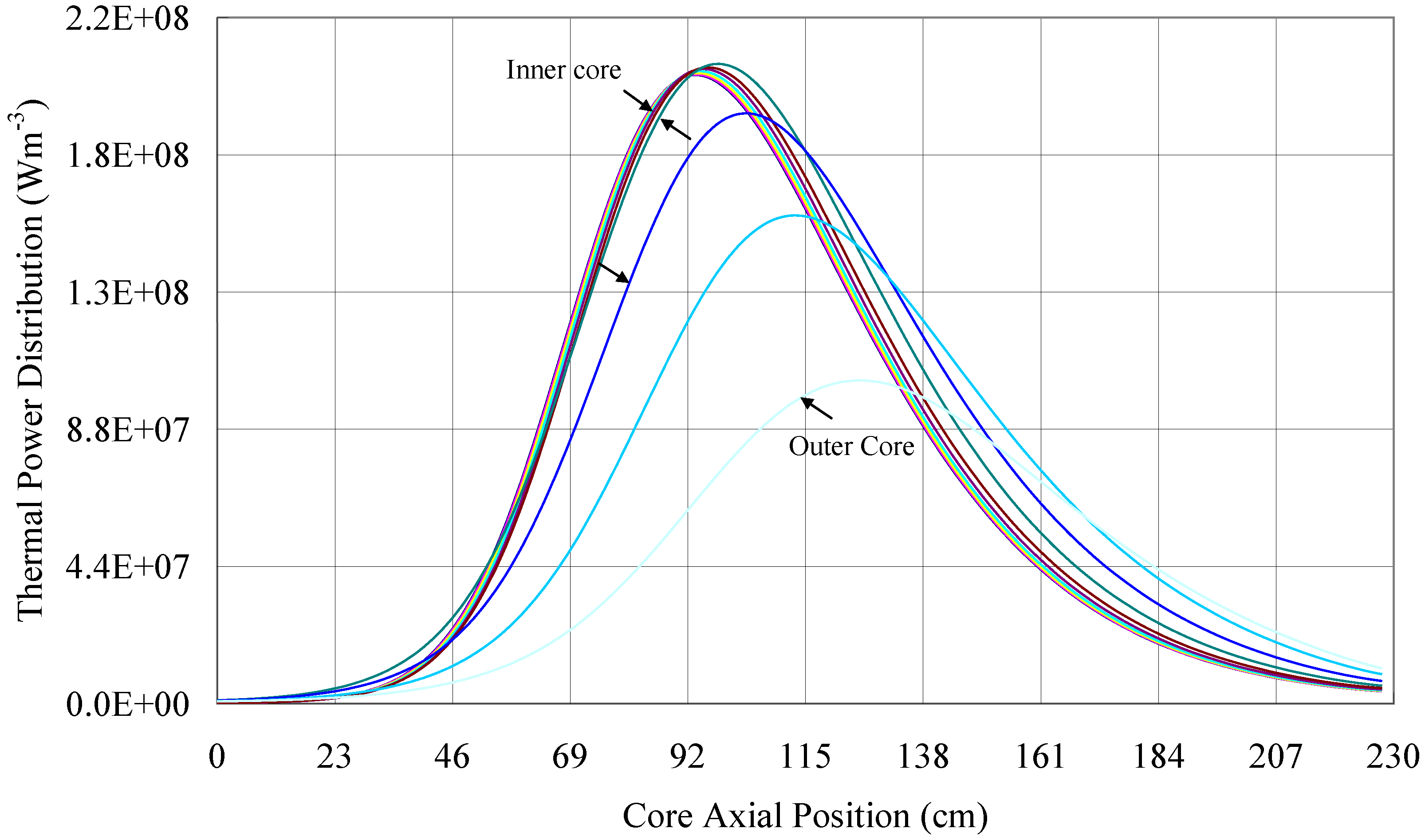
Figure 6.
The thermal power distribution.
Figure 6.
The thermal power distribution.
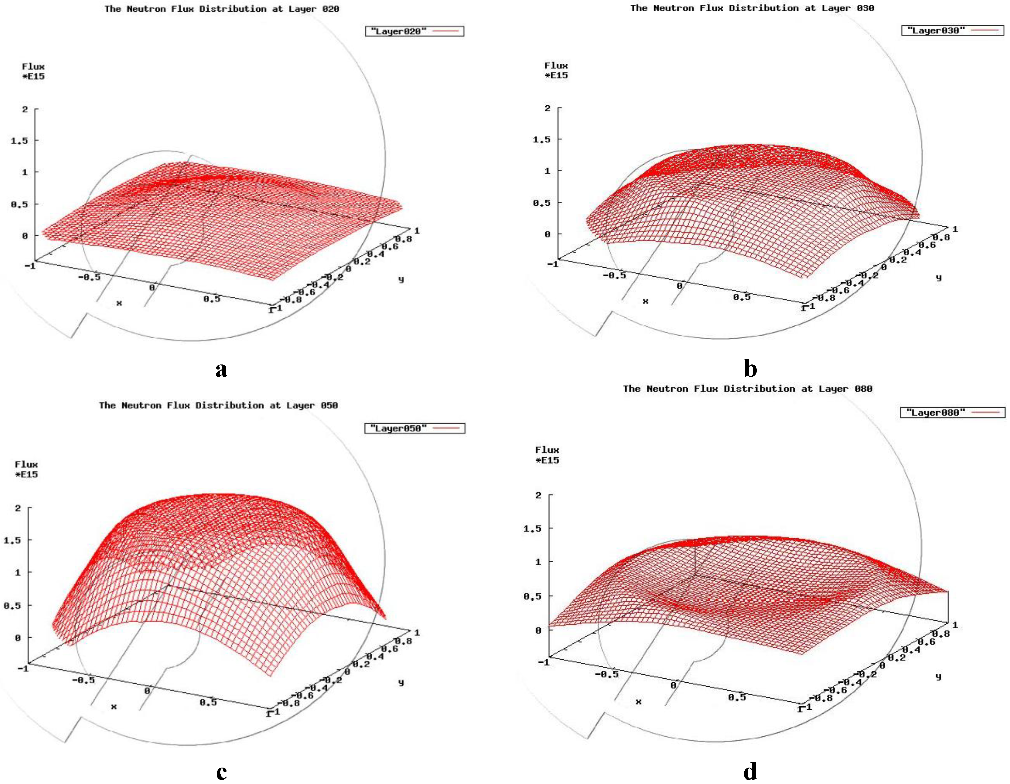
Figure 7.
(a)The 3D radial neutron flux distribution at axial layer 30; (b) layer 47; (c) layer 70 and (d) layer 90.
Figure 7.
(a)The 3D radial neutron flux distribution at axial layer 30; (b) layer 47; (c) layer 70 and (d) layer 90.
With the flat radial neutron flux distribution, the temperature peaks are efficiently cut off, leaving large margin limits, as shown in
Figure 8. The average coolant outlet temperature of the core is almost 773 K and can provide high energy efficiency. The absolute values and the discrepancies of the three temperatures are relatively small, taking advantage of the optimal characteristics of the LBE coolant and nitride fuel. Both are good heat conductors and the gap between the fuel pellets and cladding is filled with the LBE bond to enhance heat transfer. Since the pressure losses, such as the portion induced by the wrap wire of the fuel pin, are not incorporated in the calculation, the partially estimated friction pressure loss is about 0.4 MPa. To be more precise, the total core pressure loss will be presented by the CFX calculation based on our specific fuel assembly design.
Figure 8.
The temperature distribution of the hottest fuel pin and coolant channel.
Figure 8.
The temperature distribution of the hottest fuel pin and coolant channel.
2.3. The Design and Results of the 2000 MWth CANDLE Reactor
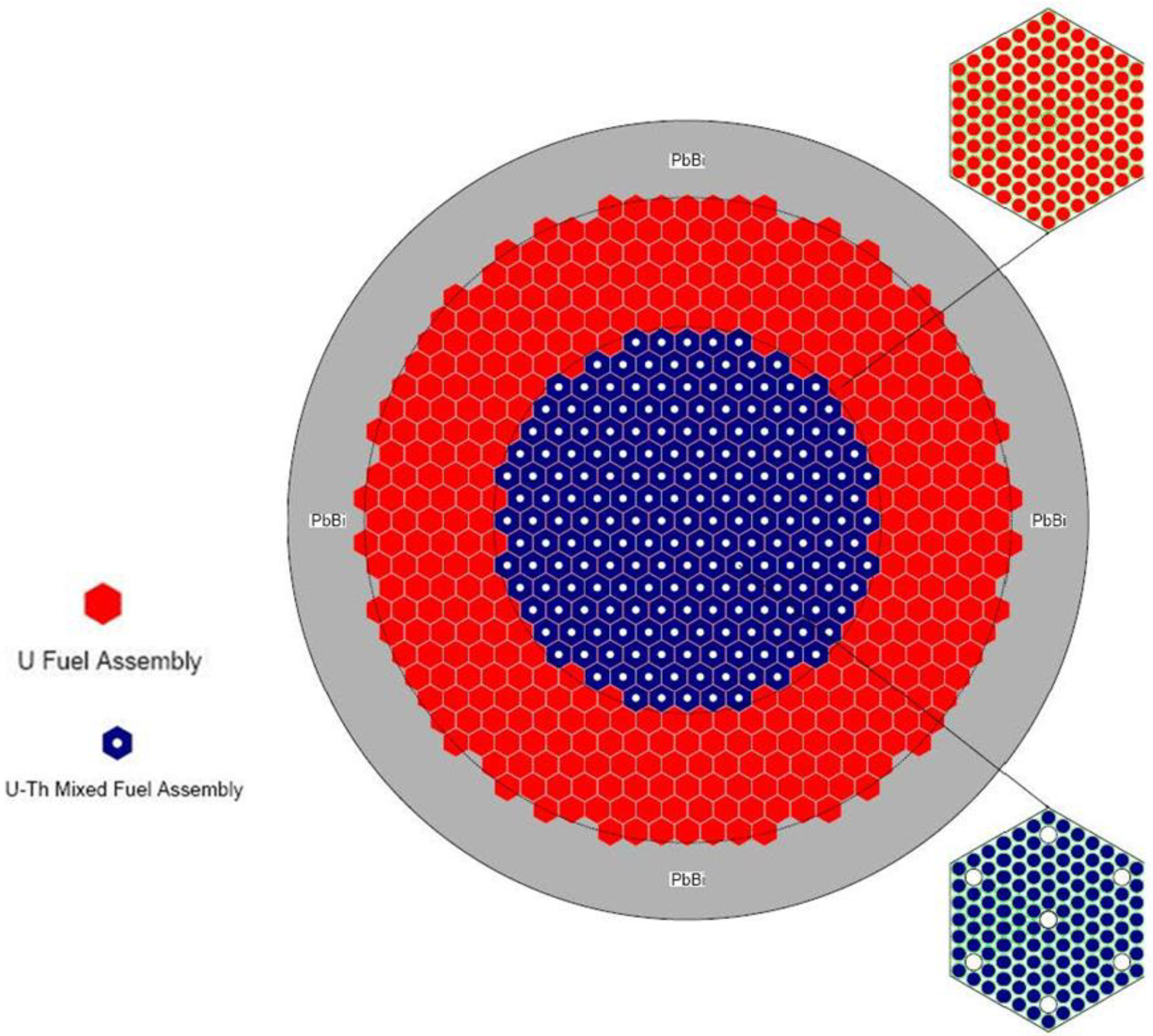
In this design, we adopted a uranium-plutonium and thorium-uranium combined fuel cycle, using the th2cm6fp50bp16F burnup chain. Different from the 1000 MWth design, the inner region is composed of the fuel assemblies containing thorium, while the outer region is filled with the uranium fuel assembly at an enrichment of 2.4%. The outer region is surrounded by a 50 cm thick LBE reflector, as shown in
Figure 9. The total empty space volume ratio in the inner region is about 5.5%, which is available for the shutdown control rod channels and experiment/detection equipment channels. The detailed design parameters of this core are shown in
Table 3.
The CANDLE reactors with a power level higher than 2000 MWth are suitable for most crowded places in the world, satisfying the rapid increase of energy demands. Such reactors could become the main supplier in the nuclear energy industry as a substitute for the present thermal reactors and fast reactors to extend the utilization of fission energy for thousands of years and, in the long run, protect the global environment. For different power level designs, we adopted the uniform geometry and configuration for the fuel pins and assemblies, considering the engineering standardization. Similar thermal-hydraulic designs have also been adopted to reduce difficulties and expenses in the system and variability in the conditions. The thorium fuel used in the inner region suppresses the peak of the radial neutron flux distribution and helps maintaining resource diversity. The LBE coolant is also adopted.
The key results for this case are shown in
Table 4.
Figure 9.
Sketch of the 2000 MWth CANDLE core configuration.
Figure 9.
Sketch of the 2000 MWth CANDLE core configuration.
Table 3.
The 2000 MWth CANDLE core design parameters.
Table 3.
The 2000 MWth CANDLE core design parameters.
| Main Design Parameters | Values/Specifications |
|---|
| Thermal Power/MWth | 2000 |
| Core Height/cm | 230 |
| Core Radius/cm | 210 |
| Radius of Inner Core/cm | 126 |
| Thickness of Reflector/cm | 50 |
| Fuel Cell Radius/mm | 6 |
| Thickness of Cladding/mm | 0.5 |
| Distance between fuel pins/mm | 0.8 |
| Fuel Material of Inner Core | Natural 82% UN、18% ThN |
| Fuel Material of Outer Core | Enrichment 2.4% UN |
| Cladding Material | HT-9 |
| Coolant Material | PbBi (44.5%–55.5%) |
| Reflector Material | PbBi (44.5%–55.5%) |
| Core Inlet Temp/K | 600 |
| Core Outlet Temp Peak/K | 800 |
Table 4.
The key results of the 2000 MWth CANDLE reactor design.
Table 4.
The key results of the 2000 MWth CANDLE reactor design.
| Key Results | Values |
|---|
| Keff | 1.0019 |
| Burnup velocity (cm/year) | 1.84 |
| Maximum discharged fuel burn-up (%) | 57.0 |
| Fuel temperature peak (K) | 916.7 |
| Cladding temperature peak (K) | 801.1 |
| Maximum Coolant Velocity/m/s | 3.1 |
When the contents of
Table 2 and
Table 4 are compared, no qualitative difference can be found. The 2000 MWth reactor is also an extremely long life nuclear battery and needs no burnup control, nor refueling. The higher power results in faster fuel consumption, resulting in a slightly larger burnup velocity. Also, the higher power level makes the core slightly hotter. All of the parameters listed in
Table 4 are well within the design limits, except for the burnup depth. As mentioned in the former section, before a more appropriate material is found, we have to face this challenge using optimized designs and measures, such as the present “recladding procedure”. The question as to how to solve this challenge more satisfactorily remains an important research objective.
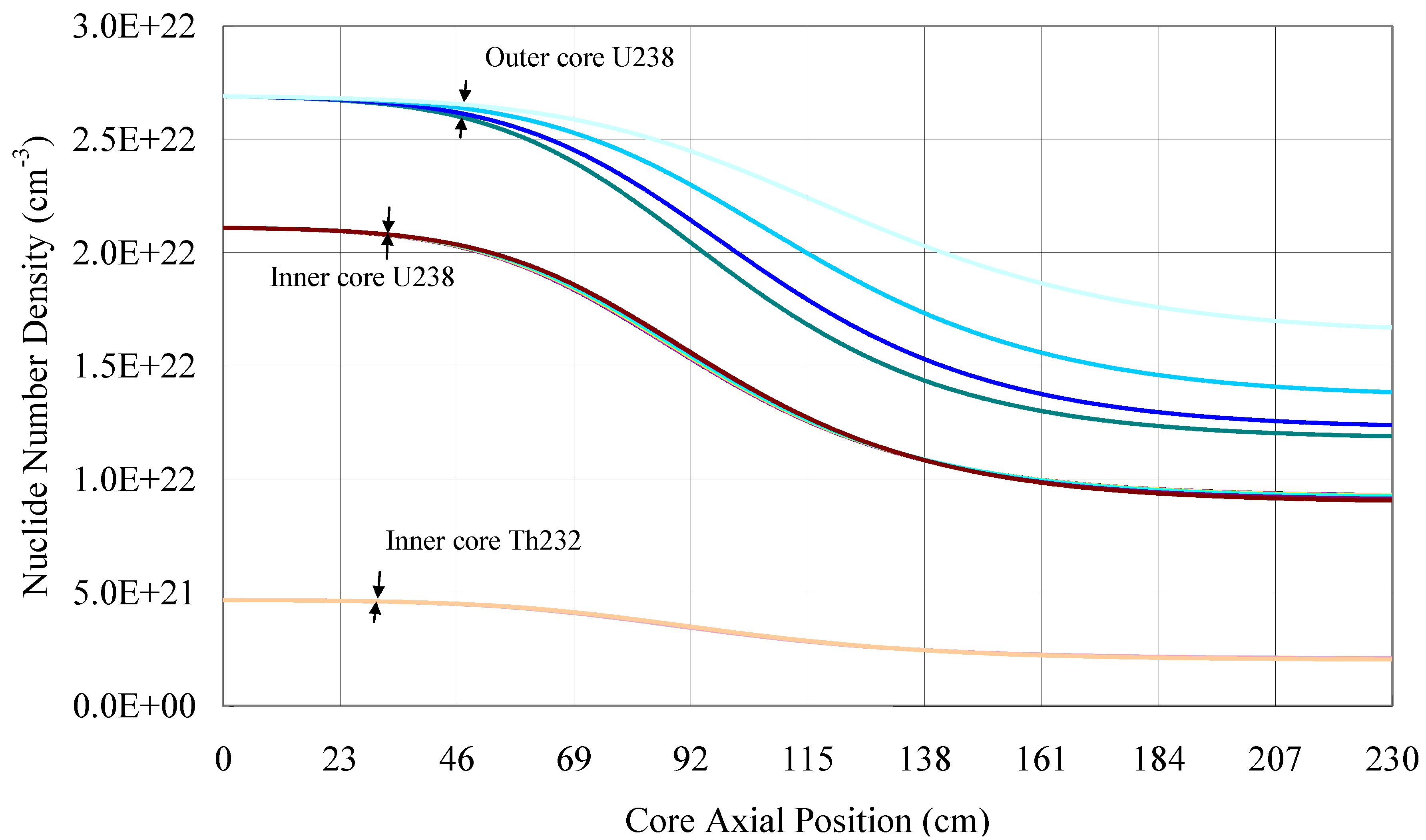
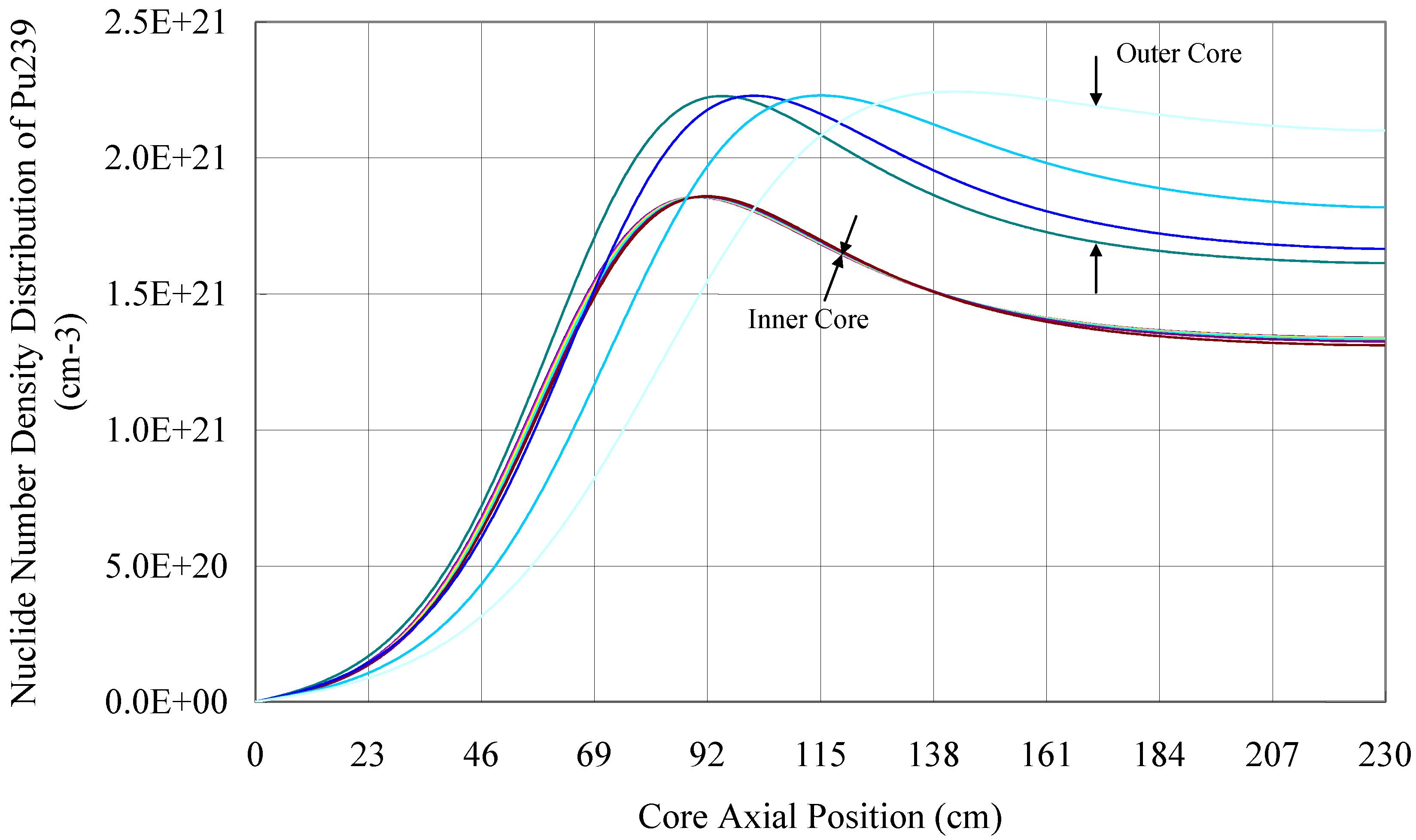
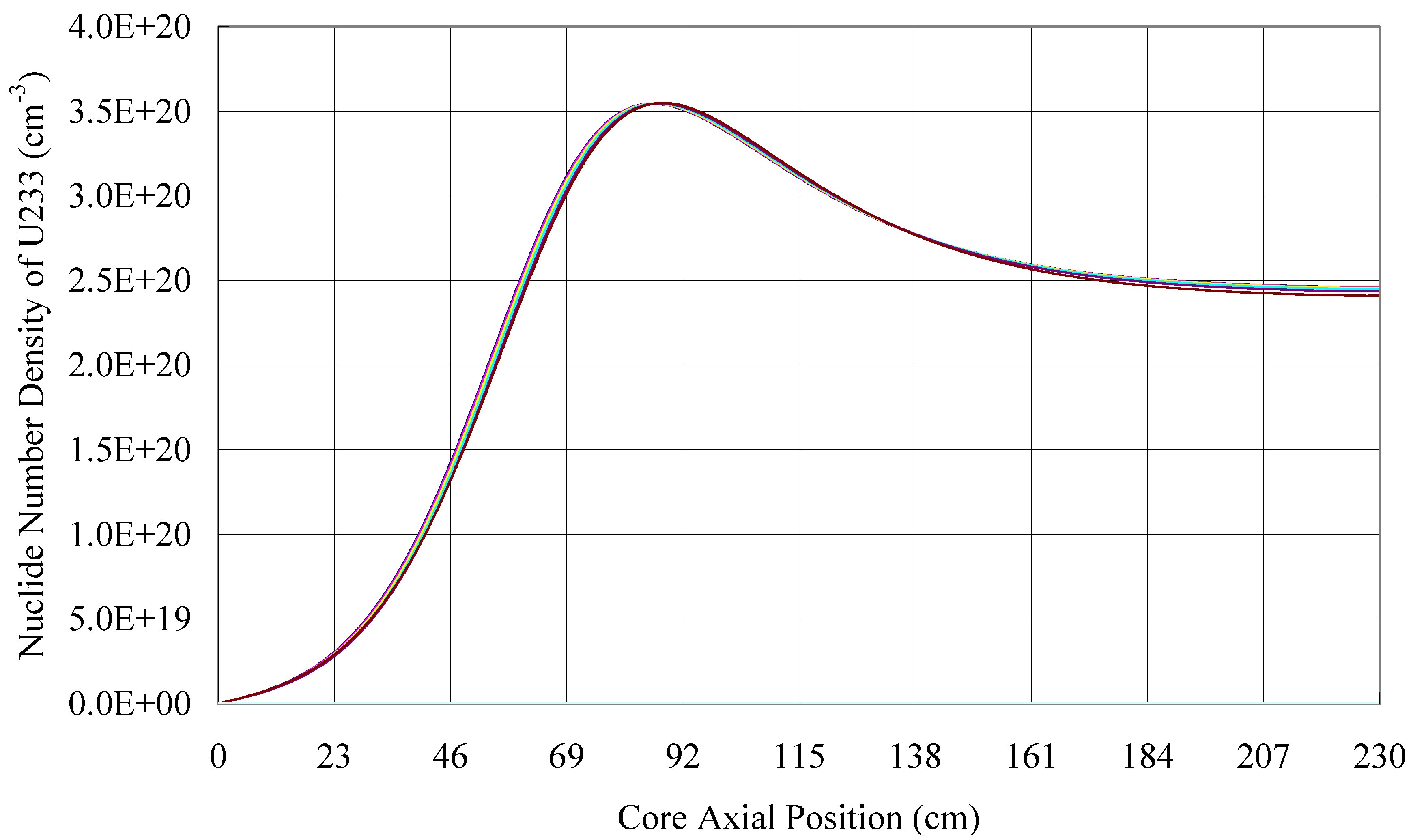
From
Figure 10 to
Figure 12, the equilibrium number density distributions of the nuclide U238, Th232, Pu239 and U233 are presented. The number density of the nuclides in the inner region is also volume weighted, in accordance with the empty space volume ratio.
Figure 10.
The equilibrium nuclide number density distributions of U238 and Th232.
Figure 10.
The equilibrium nuclide number density distributions of U238 and Th232.
Figure 11.
The equilibrium nuclide number density distribution of Pu239.
Figure 11.
The equilibrium nuclide number density distribution of Pu239.
Figure 12.
The equilibrium nuclide number density distribution of U233 in the inner core.
Figure 12.
The equilibrium nuclide number density distribution of U233 in the inner core.
The spent fuel region is generated when the burning wave moves away and the process is extremely slow. In a rather long residence time in the core, a large amount of fast neutrons from the burning region keep bombarding the heavy nuclides in the spent fuel region, such as the minor actinides, resulting in a high transmutation ratio of the CANDLE core, as shown in
Table 5.
Table 5.
The number densities of the main MAs and the plutonium isotopes in the spent fuel region of outer core.
Table 5.
The number densities of the main MAs and the plutonium isotopes in the spent fuel region of outer core.
| Nuclide | Number Density (cm−3) | Nuclide | Number Density (cm−3) |
|---|
| Np236 | 1.21e15 | Am241 | 1.05e20 |
| Np237 | 3.52e19 | Am242M | 5.62e18 |
| Pu236 | 4.46e13 | Am243 | 8.38e18 |
| Pu238 | 4.59e19 | Cm242 | 1.14e17 |
| Pu239 | 1.61e21 | Cm243 | 3.33e16 |
| Pu240 | 7.76e20 | Cm244 | 1.73e18 |
| Pu241 | 3.33e19 | Cm245 | 4.56e17 |
| Pu242 | 4.12e19 | Cm246 | 1.41e17 |
The summed up number density of Np, Am and Cm, including all their isotopes counted in the calculation, is about 1.57e20 cm−3, which is only 0.57% of that of the uranium isotopes in the fresh fuel. For a fast reactor, the corresponding ratio would be many times higher. Compared with the LWR, the spent fuel amount per produced heat energy is only 10% of LWR in the once-through cycle, according to the burnup depth. Also, if the thermal efficiency is taken into account, the ratio would be reduced to 7% or even less. The CANDLE reactor is suitable for adopting the once-through cycle, considerably reducing the indirect waste generated by the reprocessing, which can usually be thousands of times the amount of the spent fuel. The conclusion should be drawn that the CANDLE reactor is an incredible converter, burner, transmutator and environment saver all in one.
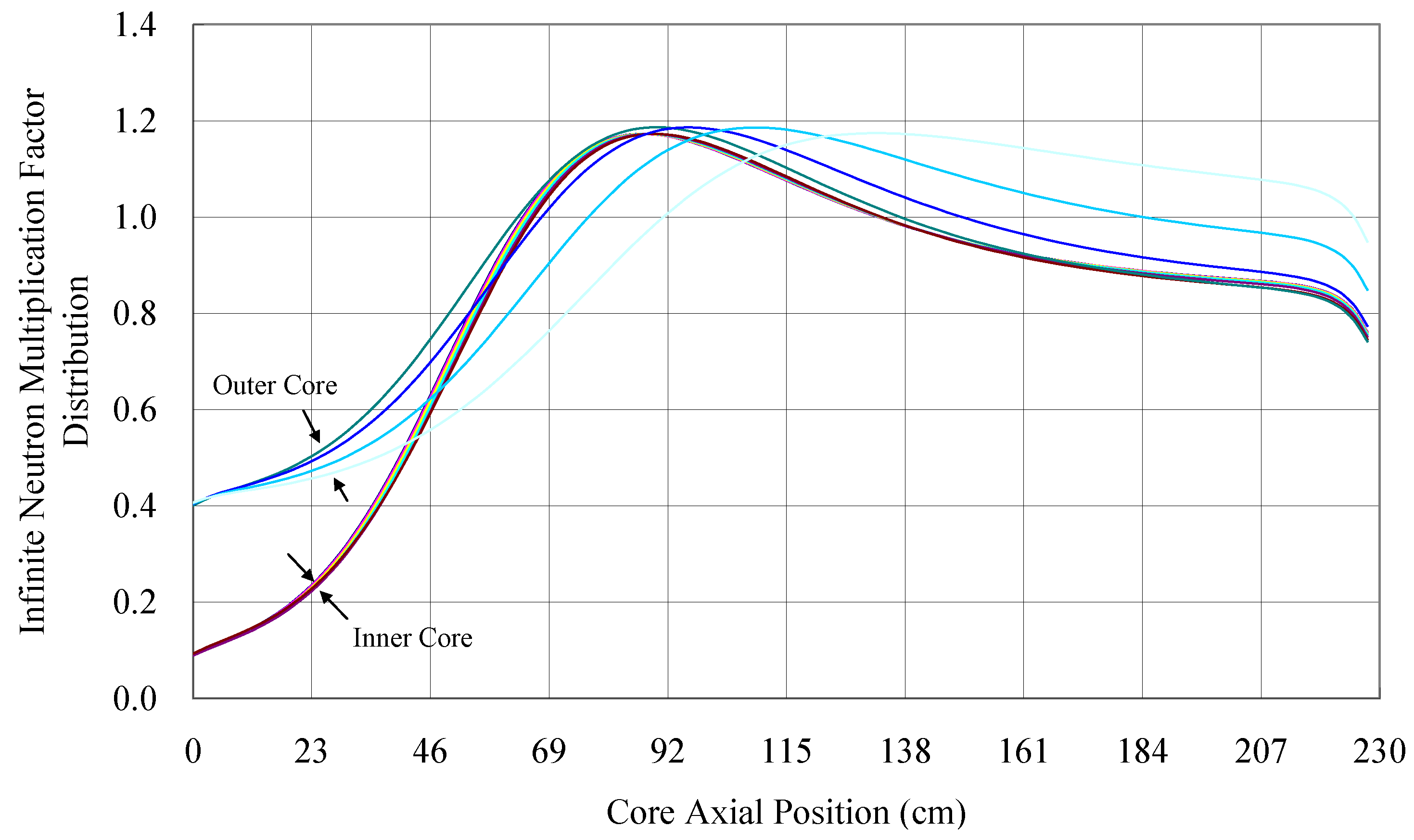
Figure 13 shows the infinite neutron multiplication factor distribution. In the inner region, the U233 transmuted from Th232 decides the distribution of the factor. In the outer region, the dominator is the Pu239 transmuted from U238.
Figure 13.
The infinite neutron multiplication factor distribution.
Figure 13.
The infinite neutron multiplication factor distribution.
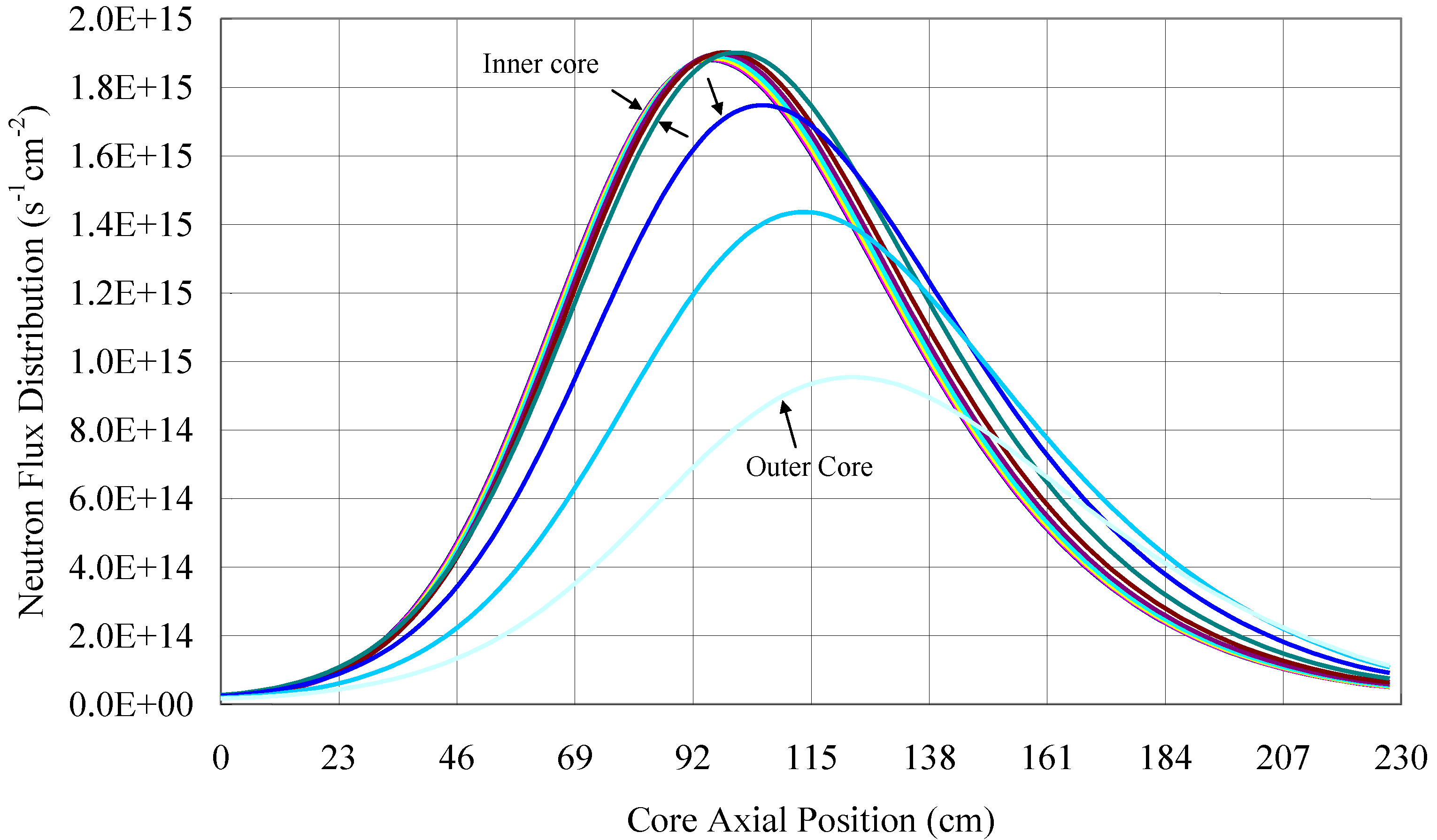
Figure 14 and
Figure 15 show that on every axial layer of the burning region, more than 50% of the area is covered by the same neutron flux and power level. More than 80% of the area is covered by the neutron flux,
i.e. between 1.9e15 cm
−2s
−1 to 1.0e15 cm
−2s
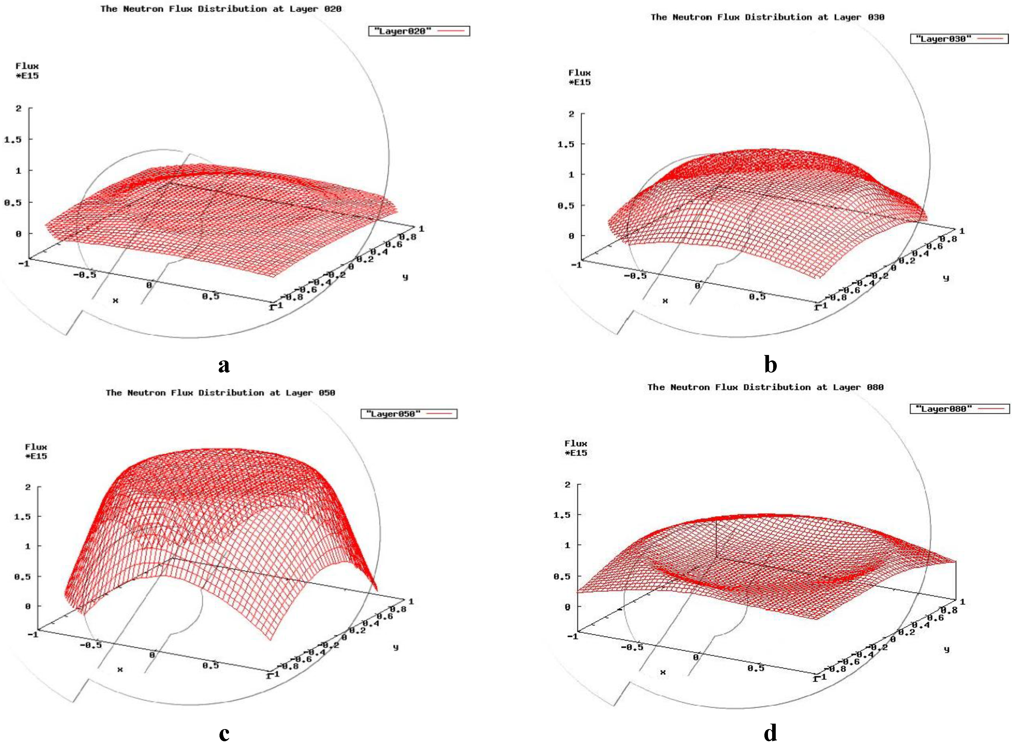
−1 at the axial flux peak. Compared with the 1000 MWth case, a much flatter flux distribution covers a larger area, as shown in the 3D figures of
Figure 16. Because the core radius is increased, the neutron loss from the inner core region introduced by radial leakage is weakened. This reminds us that a more functional reflector would enhance the flattening of the radial flux distribution. According to
Figure 17, the burning region that is exposed to the highest radiation would take about 16.2 years to reach the damage neutron fluence limit, which is about 250 dpa (5.0e23 cm
−2) from the fresh state (the counted neutrons have an energy level higher than 0.1 MeV, which is about 50% of the summation for the present case). This time limit is restricted by the maximum local radiation dose along the fuel assembly with maximum power output and the proportion of the high energy neutrons. So the radial neutron flux distribution is required to be as flat as possible to extend the time limit.
Figure 14.
The neutron flux distribution.
Figure 14.
The neutron flux distribution.
Figure 15.
The thermal power distribution.
Figure 15.
The thermal power distribution.
Figure 16.
(a) The 3D radial neutron flux distribution at axial layer 30; (b) layer 40; (c) layer 60 and (d) layer 80.
Figure 16.
(a) The 3D radial neutron flux distribution at axial layer 30; (b) layer 40; (c) layer 60 and (d) layer 80.
A CANDLE reactor core, which can operate continuously for approximately 16 years with full 2000 MWth power output, is very impressive, compared with any other fission reactors and is the obvious evolution of nuclear fission energy utilization of the human society. Another key point is that this CANDLE reactor can be realized based on currently existing technologies and materials. Furthermore, the operation capability of the CANDLE reactor will improve along with the advancements in key elements, especially the cladding material.
If we set the core life to 60 years, the burning wave will travel about 110 cm in the core axial direction, according to the burnup velocity, and the maximum neutron fluence damage a fuel assembly could get is about 1.29e24 cm−2. Seventy percent of the core will get the fluence beyond 1.0e24 cm−2 and it will take about 37 years for the most radiated fuel assembly to reach this value. If a cladding material supports the 500 dpa (1.0e24 cm−2) without any devastating integrity crisis, then 30% of the core (174 cm ~ 210 cm in the radial direction) does not need any treatment for the whole life of the core. After 37 years of full power operation without a break, recladding or just simply refueling will be needed for the first and only time in the 60 year lifespan of the core. Additionally, if a suitable material is found to survive the 645 dpa, then the whole core would realize full power operation without a break for 60 years.
The rough estimation above only considers the effect of “dpa”. For the real situation, the aging, erosion and other effects should be seriously considered too. However, these effects will not obstruct the capability and the potential of the CANDLE reactor to make nuclear fission energy utilization as simple and clean as possible.
The recladding procedure is a complicated operation involving radioactive hot cells and the technology needed is not yet ready for a large scale engineering application. It should be noted, however, that recladding is a feasible technique, which may well be much easier and cheaper than reprocessing. The following two engineering approaches could be considered as alternatives to the development of recladding technology:
• Firstly, following the CANDLE advancements, a simple refueling mode without any recladding procedure being necessary could be realized. Refueling would be carried out every 15 years conservatively, taking 250 dpa as the limit margin. Thus, in the 60 years core life, the CANDLE will require a very low-levelenriched fuel inventory for four cores and will need to be shut down four times in total. At the same time, research and radiation testing of cladding materialsshould be pushed forward. With the development of suitable materials, the refueling amount and frequency could be reduced and might well be eventually eliminated. A fast reactor with the same power level usually needs refueling every 1.5 years, i.e., in an assumed 60 year core life, it needs a fuel inventory for 13 cores, which is much higher enriched, and shutting down a total of 40 times. It becomes apparent that the CANDLE reactors are the rational substitute forfast reactors.
• Continue with the SWR (Standing Wave Reactor) development proposed by TerraPower LLC [
11,
12,
13]. Theoretically, a SWR does not need refueling or recladding, but has a complicated shuffling operation of the fuel assemblies every 2 ~ 3 years. Also, the development of cladding materials is also critical for this reactor, because better material could reduce the frequency of the shuffling operations and the amount of the fuel assemblies involved.A SWR does not automatically maintain the steady burnup or maintain the flattened radial flux distribution. Also, the frequent shuffling of the irradiated fuel assemblies poses engineering challenges. On another aspect, the burnup ratio of a SWR is lower than that of a CANDLE, introducing lower irradiation damage to the materials and lower utilization capability of nuclear resources at the same time. We could presume that the SWR is a compromise for the CANDLE for easier engineering approaches and as a support of the CANDLE in the development process for better materia
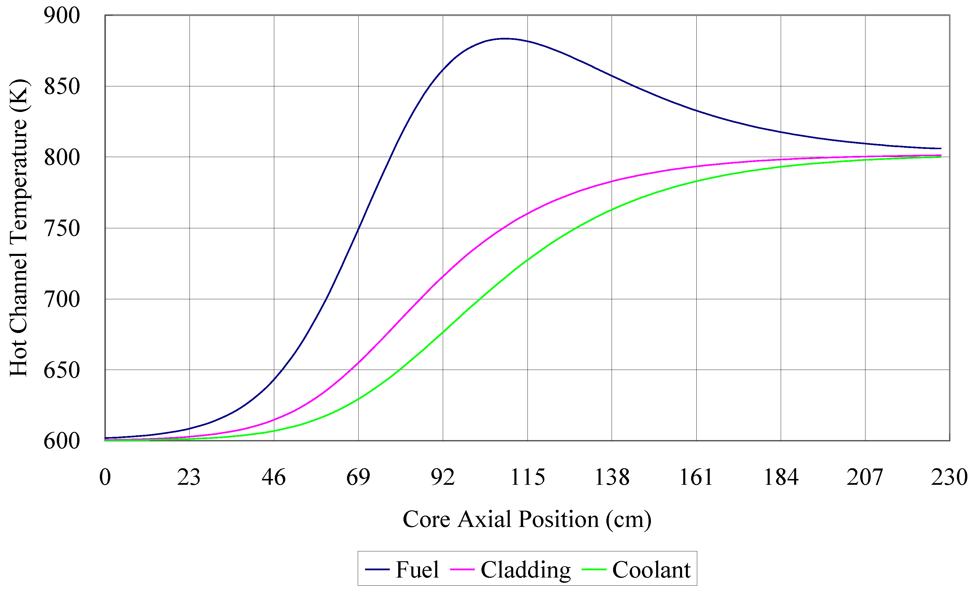
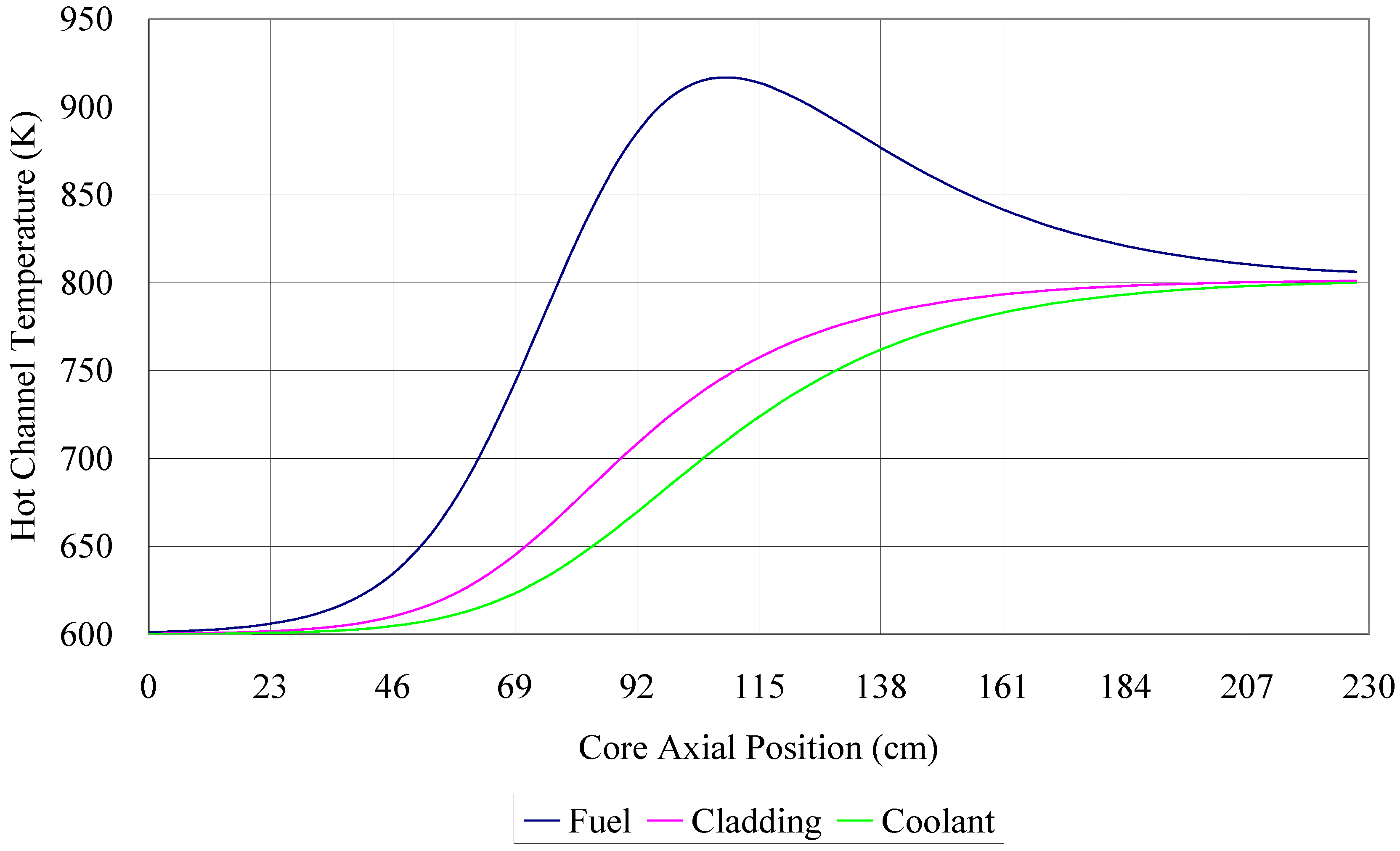
Figure 17 shows the temperatures of the hottest fuel pin and the corresponding coolant temperature distribution along the core axis. We can conclude that the core operates with large safety margins. The partially estimated friction pressure loss is less than 0.9 MPa and usually a large pressure loss of the primary loop could be predicted for a forced LBE cooled reactor with large power output.
Figure 17.
The temperature distribution of the hottest fuel pin and coolant channel.
Figure 17.
The temperature distribution of the hottest fuel pin and coolant channel.


