1. Introduction
The concepts of science, including concepts related to sustainability such as exergy and embodied energy, were developed to describe aspects of the universe. A convincing example of the usefulness of embodied energy and exergy for analyzing systems which transform energy is the generator circuit-breaker (GCB) disconnection process.
Nowadays, the electric connection circuits of power plants (based on fossil fuels as well as renewable sources) entail GCBs at the generator terminals, since the presence of that electric equipment offers many advantages related to the sustainability of a power plant [
1,
2,
3,
4,
5,
6,
7]. A classic circuit-breaker is an automatic electrical switch designed to protect against inherent operation faults, such as overload or short-circuit. A generator circuit-breaker is located between the generator and the main step-up transformer, this location influencing the operating conditions since GCBs are significantly more difficult to apply to some operating regimes than classical network circuit-breakers [
1,
3,
4,
6]. Consequently, the electrical and mechanical performance required of a GCB exceeds the requirements of a standard distribution circuit-breaker [
8]. Generally, a circuit-breaker must detect a fault condition, and once a fault is detected, the electric contacts within the circuit-breaker must open to interrupt the circuit [
9,
10]. In an alternating current (a.c.) circuit, the interruption of a short-circuit is performed by the circuit-breaker at the natural passing through zero of the short-circuit current. During the current interruption, an electric arc is generated between the opened contacts of the circuit-breaker. This arc must be cooled and extinguished in a controlled way [
1,
5,
9,
10].
Figure 1.
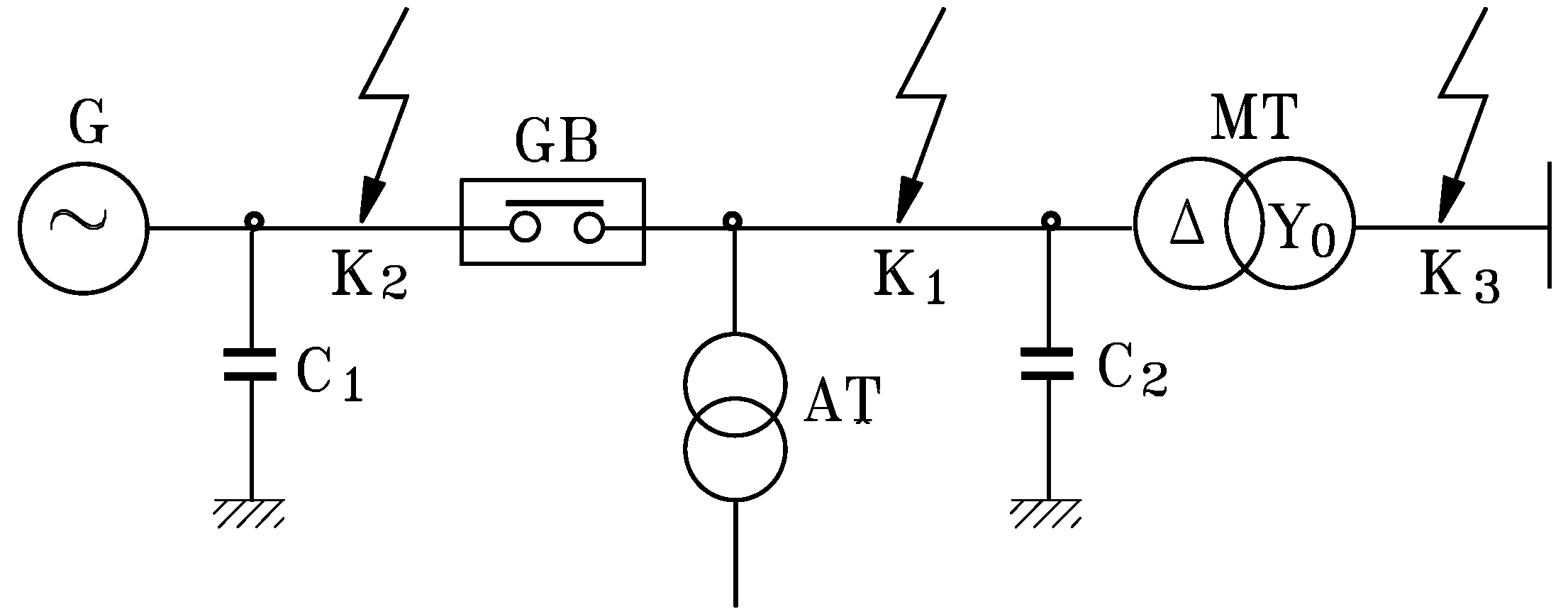
Possible faults interrupted by a generator breaker GB.
Figure 1.
Possible faults interrupted by a generator breaker GB.
The configuration of the key fault current encountered by the generator breaker (GB) is represented in
Figure 1, and details are as follows:
- -
Faults at location K1 are called Generator (G)-source faults or Generator-fed faults (which can be insulated or grounded three-phase and two-phases short-circuits);
- -
Faults at location K2 are called System-source faults or Transformer (MT)-fed faults (which can be insulated or grounded three-phase and two-phases short-circuits);
- -
Faults at location K3 are called Generator-fed faults, on the high voltage side of the main step-up transformer (which can be insulated or grounded three-phase and two-phases short-circuits, as well as single-phase short-circuits).
To interrupt these kinds of faults, generator circuit-breakers must be capable of interrupting not only the high symmetrical fault current, but also the higher asymmetrical faults currents resulting from high d.c. components of the fault current [
1,
2,
11,
12,
13]. Here arises another sustainability requirement for generator circuit-breakers which are subjected to a unique demanding condition, called delayed current zeros [
1,
14,
15]. Since circuit breakers interrupt on the current zero crossing, generator circuit-breakers must be able to withstand longer arcing times and greater electrical, thermal and mechanical stresses when interrupting such faults [
1,
2,
4,
14,
15].
The highest asymmetry of the short-circuit current appears at Generator-fed fault (location K1), and this is the reason that the next section of this study encompasses an analysis of delayed short-circuit current zeros.
2. Asymmetrical Currents of Sudden Three-Phase Short-Circuit at Generator Terminals
Research findings [
5,
6,
7,
11,
12,
14] show that an synchronous generator stator can operate via high asymmetrical short-circuit currents, which will not pass through zero (at least on one phase) many time periods after a fault appearance. The phenomena which occur in the case of short-circuit currents interruption determine the main stresses of the generator circuit-breaker [
1,
2,
4,
15], and the current interruption requirements of a GCB should be significantly higher than for the distribution network circuit breakers.
In this paper the time interval is assessed when the current, in the case of the sudden three phase short-circuit, has not a zero passing. To shed light on the proper moment when the generator breaker must operate, using the space phasor of the short-circuit currents, the time expression to the first zero passing of the short-circuit current will be determined. We aim to investigate the manner in which various factors influence the zero passing delay of the short-circuit current.
A representation of phase currents in the case of sudden short-circuit at the terminals of synchronous generator emphasizes that, regardless of the switching conditions, within each time cycle there are two zero passings of the short-circuit current [
1,
2]. Still, research findings [
3,
4,
5] show that the synchronous generator stator is possibly can operate by highly asymmetrical short-circuit currents, which will not pass by zero—at least on one phase—many cycles (time periods) after the fault appearance. The long delay of a zero passing short-circuit current is a unique fault characteristic that illuminates the high asymmetrical currents which must be interrupted by the generator circuit-circuit. To address meaningfully the operation conditions for the generator circuit-breaker in this study, we analyze the three-phase short-circuit at the terminals of electric station synchronous generator, with emphasis on the analytical relation of the delay zero passing of the short-circuit current, taking into consideration the electrical machine parameters and the features of the load preceding the short-circuit.
The study of transient processes of a synchronous generator sudden short-circuit can be performed with the space phasor of short-circuit currents [
1,
2]. Thus, after some mathematics, the relation of short-circuit current space phasor
iss to the stator frame is obtained as follows:
Where
is the rotating component with angular speed 2
ω of the short-circuit current space phasor, whose amplitude decreases towards zero with the time constant
Ta. Also,
denotes the rotating component with angular speed ω of the short-circuit current space phasor, whose amplitude decreases [
1,
2] with the time constants
T"d,
T'd and
T"q towards the value √2
E0/
Xd corresponding to steady-state short-circuit currents. Also,
is the fixed component of the short-circuit current space phasor, with the amplitude decreasing towards zero with the time constant
Ta.
The scalar expressions of the sudden three-phase short-circuit currents iA, iB and iC through the stator phase windings (A, B and C) can be obtained by simple projections of the space phasor iss pe on phase directions A, B and C. Consequently: iA(t) = PrA{iss} = Re{iss}; iB(t) = PrB{iss} = Re{a2iss}; iC(t) = PrC{iss} = Re{aiss}, where we utilize the complex operator a = e j2π/3.
As an example, the sudden short-circuit current through the stator phase A is as follows:
where
Xd is the phase winding reactance in the direct axis;
X’d is the transient reactance in the direct axis;
X”d is the sub-transient reactance in the direct axis;
Xq is the phase winding reactance in the quadrature axis;
X”q is the sub-transient reactance in the quadrature axis;
T’d is the direct axis short-circuit transient time-constant;
T”d is the direct axis short-circuit sub-transient time-constant;
Ta is the armature short-circuit (d.c.) time-constant;
Idin = (
E0 −
U cos
θ)/
Xd is the initial effective value of the direct axis component corresponding to the load current before the short-circuit.
Note that an a.c. circuit-breaker operates the circuit disconnection at the zero passing of the current. Still, in the case of a generator circuit-breaker the first zero passing of a short-circuit current can be delayed, since the analysis of relation (5) highlights three components of the short-circuit current, respectively: an aperiodic current, and the fundamental and the second harmonic currents. The full short-circuit current will not have a zero passing as long as the periodic component with fundamental frequency will be smaller than the resultant of the other two component. Since the last two components of the short-circuit current are damping with the same time-constant Ta, we will take them into consideration together, as the aperiodic pulsating current. Consequently, the time until the first zero passing of the short-circuit current iA is given by the smaller positive solution of the equation iA(t) = 0.
It must be noted that the initial value of the aperiodic pulsating current of the sudden short-circuit depends both on the rotor position at the short-circuit appearance (through the angle
α0), and on the load magnitude before the short circuit (through the internal angle
θ). For instance, on the phase A, the maximum of the aperiodic pulsating current will be reached under the condition:
The aperiodic pulsating current will miss only if at the moment of short-circuit appearance:
Further we account for the hard situation, when α0 = −θ, corresponding to the maximum value of the aperiodic component of the short-circuit current in the phase A (see Equation (5)). This situation is related to the longest asymmetrical short-circuit current, with the maximum delay of the first zero passing.
Analytically, the zero passing delay time
tzθ (the duration of the asymmetrical short-circuit current) must satisfy the equation:
Under the assumption
X"q =
X"d and neglecting the small contribution of the terms damped with the time constants
T"d and
T"q, the following is obtained:
Note that under the approximations considered, Equation (9) designates a time
Tmax higher than
tzθ.
Taking into consideration that the delay time is influenced by the synchronous machine parameters and the load conditions which precede the short-circuit, several numerical simulations are presented of the asymmetrical currents performed for the case of the sudden three-phase short-circuit at the terminals of synchronous generators from Turceni-Romania electrical power plant.
The calculated relations and simulations of the short-circuit currents (
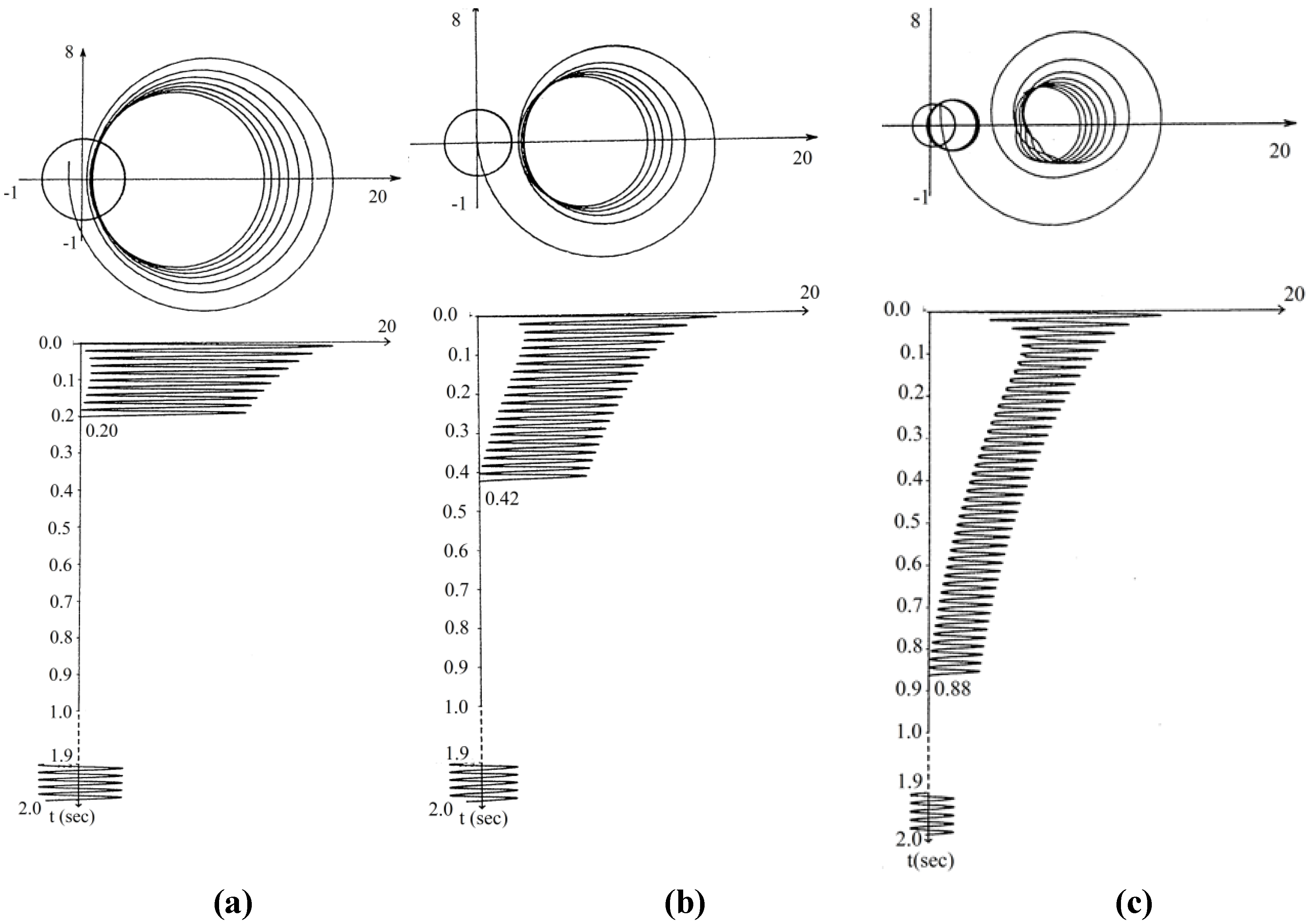
Figure 2) fed from the generator emphasize fundamental aspects with direct implications on commutations equipment, as follows:
Figure 2.
Current locus (upper representation) and short-circuit current on phase A (lower representation) for a generator of 370 MVA of Turceni power plant, after an operation at rated load, with: (a) cosφ = 0.8 and sinφ = 0.6. (b) cosφ = 1. (c) cosφ = 0.8 and sinφ =−0.6.
Figure 2.
Current locus (upper representation) and short-circuit current on phase A (lower representation) for a generator of 370 MVA of Turceni power plant, after an operation at rated load, with: (a) cosφ = 0.8 and sinφ = 0.6. (b) cosφ = 1. (c) cosφ = 0.8 and sinφ =−0.6.
Equation (9), although an approximate solution, emphasizes the immediate conclusions on upper value of Tmax corresponding to the first zero passing of the short-circuit current. Thus, Tmax is directly influenced by the machine parameters through the ratios T'd/Ta and X'd/X"d.
Related to the load regime preceding the short circuit, Equation (9) highlights that Tmax has much higher values as Idin and Uq = U cosθ decrease, indicating that as the internal angle θ rises the generator excitation degree lowers.
The previous remarks are confirmed by the short-circuit current simulations. The first zero passing of the short-circuit current could occur only after 0.2–0.4 s after the short-circuit appearance, if the generator previously has operated with an inductive load. The asymmetrical current duration can reach 0.6–0.8 s if previously to short-circuit the generator was operating in an under-excited regime.
The action of voltage regulator should be also taken into consideration. Recall that a short circuit means a drop of the voltage at the machine terminals, and could note that moment precisely when the generator regulator has the tendency to raise the voltage to the rated value. For that purpose, the regulator increases the excitation current to the maximum limit. Because the field winding operates only on the direct axis, the regulator determines an increase of the short-circuit alternating component on this axis. The alternating current on the quadrature axis is not influenced by the regulator action. This way, the regulator influences the short-circuit current zero-passing moment. A phase current has a zero passing at the moment when the instantaneous value of the alternating component with the pulsation ω is greater than the pulsating current. The increase, determined by the regulator, of the short-circuit alternating current on the direct axis, always has a favourable effect on the breaking conditions, because it is accompanied by the rise of the alternating component of the short-circuit total current. Consequently, the corresponding increase of electric energy represents a useful component, meaning that exergy is not destroyed during the action of the voltage regulator.
3. Exergy Analysis of Electric Arc in Generator Circuit-Breaker
Electric arc interruption is of great importance because an uncontrolled electrical arc in the apparatus could become destructive since, once initiated, an arc will draw more and more current from a fixed voltage supply until the apparatus is destroyed [
4,
7,
9,
10,
16]. To improve electric arc interruption, therefore, the circuit-breakers encompass chambers for the electric arc extinction [
9,
10].
Although the phenomena produced in the electric arc at the terminals of the circuit-breaker are complicated and not completely explained, the concept of exergy is useful for understanding the physical phenomena [
17,
18,
19,
20,
21,
22]. Investigations of electrics show that the limits between the microscopic and macroscopic phenomena are fragile and certain phenomena could be studied in related frames of work. The electric arc that occurs during the interruption processes in a circuit-breaker can be studied as a very high temperature (up to 50,000 K) continuous plasma discharge, and thermodynamic parameters must be taken into consideration; alternatively it could be seen as an electric conductor of a resistance depending on the current intensity (under a constant low voltage) and studied within the Faraday’s macroscopic theory.
We approach the electric arc analysis within Faraday’s theory for shedding light from the exergetic point of view of the interruption process. The arc resistance
rA may be considered as purely ohmic resistance, irrespective of whether a direct or alternating current arc [
9,
23,
24]. As known, an electric arc has a non-linear relationship between current and voltage, and once the arc is established (for instance at the separating electrodes), increased current results in a lower voltage between the arc terminals. Still, the voltage drop within the arc column can be considered as constant, and we will approach the following phenomena under this assumption
uA =
UA = const. For an electric arc the current density is quite high (for instance at the cathode the current density may be as high as one million amps per square centimetre), and the voltage drop
uA within the arc is low. The arc resistance
rA is a variable quantity that diminishes with increasing current and may found from the voltage-current characteristic of the arc [
9,
10,
23,
24]. Under the previous assumption the arc resistance is given as follows:
where
uA is the voltage across the circuit-breaker terminals and
i is the instantaneous value of the short-circuit current, according to relation (5).
With this result, we can write the electric arc power as:
The energy embedded in the arc circuit during its burning is:
where
Tmax is the arc duration, which is taken in our study to mean the duration of the asymmetrical short-circuit current until the first zero-passing, as expressed by Equation (9).
The amount of the energy embedded in the arc circuit between separating contacts is the most important factor governing the design of circuit-opening equipment. On one hand, if the electric arc does not appear, the network embedded magnetic energy would be converted to energy embedded in the electric field of the interrupted circuit, leading further to high over-voltages in the network. On the other hand, the circuit-breaker must resist the thermal stress of the energy embedded in the burning arc column.
An energy balance of the arc circuit can be assessed by writing the embedded energy
WA as:
where
WS is the electric energy delivered to the arc circuit from the supply source (the electric generator, in this study) during the arc burning, expressible as
and
WM is the energy embedded in the magnetic field of the interrupted circuit,
i.e.,
Here,
Im denotes the peak value of the short-circuit current;
L the inductance of the generator windings corresponding to different states (sub-transient, transient and steady-state short-circuit) of the magnetic field in the generator; and
R =
rA +
ra is the total resistance of the interrupted circuit, entailing the arc resistance
rA connected in series with the resistance
ra, which is much smaller, of the synchronous machine armature winding.
Consequently, in the circuit which includes the fault, the time constant of the armature pulsating current decreases according to the relation:
From an exergetic point of view we can write the exergy balance of the interrupted circuit during the arc burning as:
where the input exergy
Xin is represented by the energy delivered to the arc circuit from the electric generator over the time
Tmax of arc burning,
i.e.,
Also, the output exergy
Xout is that part of the energy supplying of the burning arc circuit during
Tmax which is converted to thermal energy, and that could be seen as representing the useful part of energy in the interrupting process,
i.e.,
The stored exergy
Xstored is represented by the energy embedded in the magnetic field of the generator windings, corresponding to different states (sub-transient, transient and steady-state short circuit), and embodied in the arc circuit:
At the instant when the current passes through zero, the energy embedded in the magnetic field of the interrupted alternating-current circuit is returned to the source of supply.
At this point, it is useful to note and discuss several important points:
Taking into consideration the previous findings one could conclude that the appearance of an electric arc at the terminals of the circuit-breaker should not be seen as a damaging phenomenon since, if the electric arc would not appear the network embedded magnetic energy would be converted to electric energy, leading further to high over-voltages.
Due to the exergy of the arc, the aperiodic pulsating current of the short-circuit currents will decrease very quickly, starting at the moment of contact separation. Since the alternating components with the pulsation ω are not influenced by this resistance increase, the output exergy of the electric arc determines the first zero-passing of the phase currents and reduces the circuit-breaker stress. For an analytical assessment of the described phenomena, it is useful to know the ratio rA/ra. Consequently, during the energy conversion process of a short-circuit at the generator terminals, the exergy is not destroyed, since the arc thermal energy is used further in the interrupting the highly asymmetrical short-circuit currents, through the arc resistance rA which diminishes the time interval Tmax until the first current zero-passing.
Also, since, in the high currents domain, the electric arc voltage actually remains constant, the arc resistance increases, even when the current is decreasing. For a simple calculation, it is preferred to choose, on the stationary characteristic of the arc, the minimum value of the resistance rA, corresponding to the maximum possible short-circuit current and to consider this value as constant. With this electric arc resistance, which is less than the real value, the result can be calculated. In the case where we obtain the highest values of the time Tmax, meaning a three-phase short-circuit at the terminals of the generator of 370 MVA, having the pulsating component damping time constant Ta = 0.437 s, we can recalculate this constant, taking into account the arc resistance, which has a value of 0.05 Ω. Then, we find TaA = 0.073 s, meaning that the time constant of the pulsating component is reduced by 83.3%.
4. Modelling Transient Recovery Voltage (TRV) at Interruption of Short-Circuits Fed by Main Transformer {PRIVATE}
Just after the short-circuit current interruption by the generator circuit-breaker (when the GCB has been subjected at the metal contact terminals to high temperatures, reported to be 20,000 K, and for special types of arcs up to 50,000 K [
9,
10,
25,
26,
27], between its opened contacts arises the transient recovery voltage (TRV) which constitutes the most important dielectric stress after the electric arc extinction [
7,
25,
28]. If the rising rate (RR) of TRV exceeds the rising rate of dielectric strength across the open gap within the extinction chamber of the GCB, the electric arc will rekindle (re-strike) and this time the electric arc exergy will be entirely used in a mechanically destructive process determined by the electrodynamics forces. Since the magnitude and shape of the TRV occurring across the generator circuit-breaker are critical parameters in the recovering gap after the current zero, in this paper we model, for the case of the faults fed by the main step-up transformer, the equivalent configurations with operational impedances, for the TRV calculation, taking into account the main transformer parameters, on the basis of the symmetrical components method. This study focuses on this fault location because the transformer-fed-fault currents can be very high since the full energy of the power system feeds the faults.
The dielectric strength within the extinction chamber of the circuit-breaker should increase at a rate higher than the TRV; otherwise the electric arc may re-strike. The circuit-breaker capability in interrupting the new arc is strongly affected since the gas-filled space between the two electrodes has already an important conductivity and this time the electric arc exergy would be entirely used in a destructive process.
Although the mechanical disconnection of the three phases is performed simultaneously, because of the currents angle phase, the arcs extinction on the phases cannot be simultaneous. It is switching, first, the arc on the phase so its current is passing first through zero. Therefore, the TRV on the three phases are different, even in the same three-phase fault interruption. Moreover, the TRV occurring across the generator circuit breaker depends both on the fault location and on the fault nature. In the framework of this paper, we determine the TRV when the short circuits fed by the main transformer (MT) are interrupted, using the operational symmetrical components method.
4.1. Symmetrical Components Method
Basically, any non-symmetrical three-phase system of currents or voltages can be decomposed into two symmetrical three-phase systems (of different sequences) and a system of single-phase quantities [
23,
29]. The method application presumes linearity, having been used together with the symbolic representation, in a simplified complex, of the sinusoidal quantities. On basis of this transformation, applied to the phase instantaneous quantities of a three-phase system, we obtain complex quantities (which lose their physical significance), named
+,
−,
0 coordinates or
instantaneous symmetrical components. In the paper we follow the same idea of transformation of phase instantaneous quantities at the generator circuit-breaker terminals, in the moments subsequent to its disconnection.
The TRV occurring across the generator circuit breaker is considered only at t > 0, like a damped oscillation by high frequency (f >> 50 Hz), starting from zero. Consequently, it can be noted that both the TRV and the high frequency currents and voltages achieve the original function conditions.
Applying the operational calculus to the relations determined by the instantaneous symmetrical components method, we obtain the
operational symmetrical components (o.s.c.) of the phase voltages and currents [
23,
28]. Moreover, the o.s.c. of the phase voltages and currents—on the main transformer side—are related by operational equations, in the form:
where
Zt+(p),
Zt-(p) and
Zt0(p) denote the
phase operational impedances of the MT in the symmetrical regimes by positive, negative and zero sequences.
Applying the o.s.c. method, the operational image of the TRV occurring across the GB poles after the current interruption can be determined. If the phase current interruption is modelled by the current injection
ik—equal, but opposite to the eliminated one—the operational image of the TRV occurring across the generator breaker can be finally expressed in mathematical form:
where
Ik(
p) represents the operational image of the switched current, and
Ze(
p) represents the operational equivalent impedance across the generator circuit breaker.
The method is general, and is suitable for application at the poles of any breaker, for any eliminated fault type, if both the elements across it and the network configuration are known.
Further in the paper we determine the TRV when short-circuits fed by the main transformer are interrupted.
4.2. Transient Recovery Voltage (TRV) Configurations Modelling
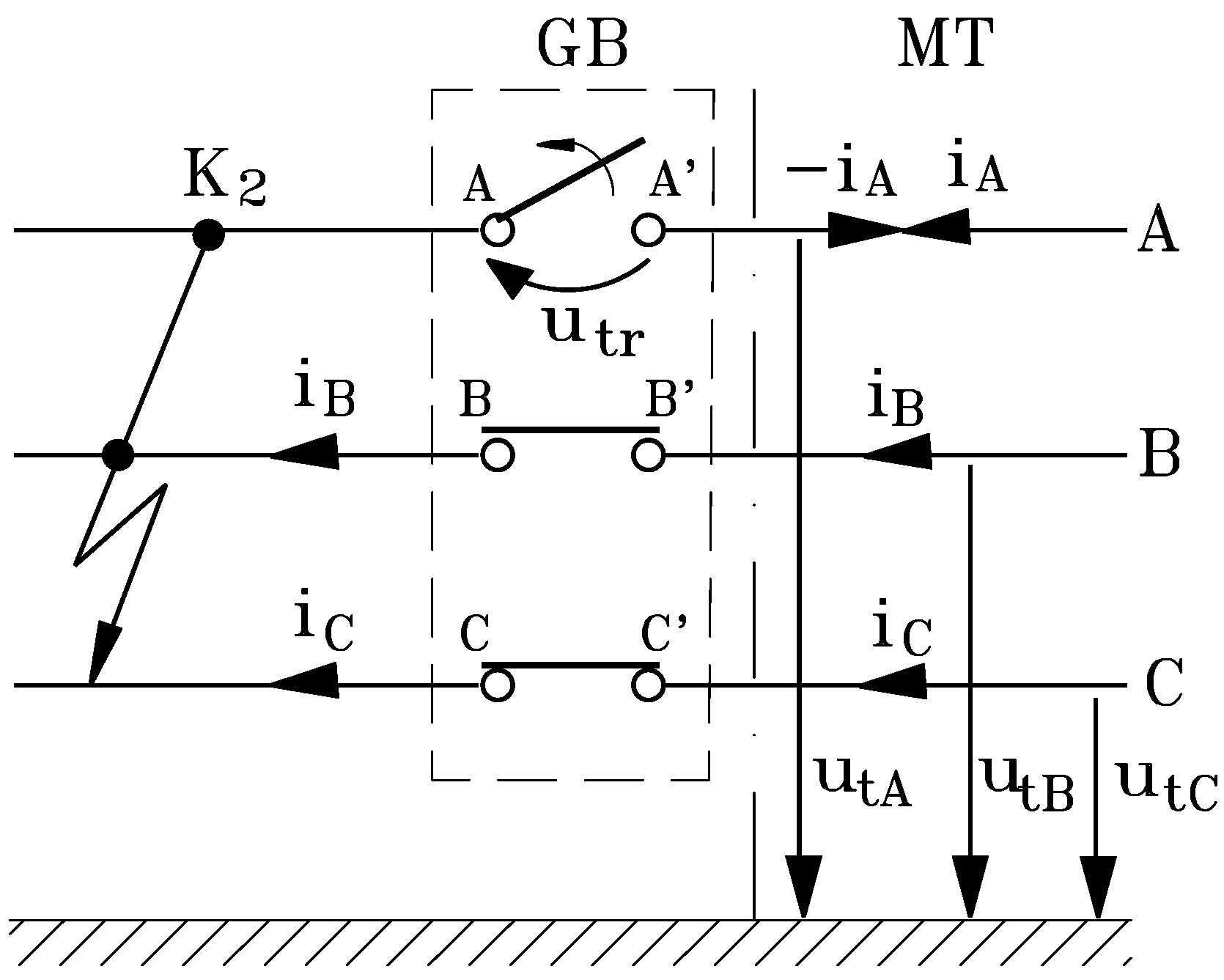
The currents of short-circuits in K2 (and interrupted by GB) are fed by the main transformer (MT). The generator transformers taken into consideration have the windings connected by the configuration Dy0. Consequently, the GB can be submitted to the insulated or grounded three-phase and two-phases short-circuits. In the paper, for illustration, we analyze the insulated three-phase and two-phase short-circuits.
4.2.1. TRV Occurring at Insulated Three-Phase Short-Circuit Disconnection
The TRV calculation configuration for the moment of the GB first phase opening is represented in
Figure 3.
The current interruption has been considered as result of injection on phase
A of the current
ik = -
iA, under the restriction:
and the TRV occurred at the pole
A-A' is:
Figure 3.
First phase opening at insulated three-phase short circuit.
Figure 3.
First phase opening at insulated three-phase short circuit.
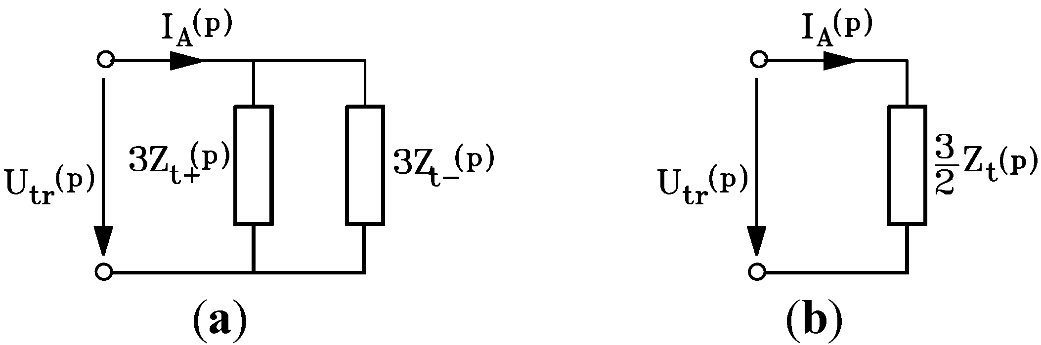
Applying the o.s.c. method, the TRV operational equation takes on the form:
Equation (25) allows the operational representation in
Figure 4a.
When
Zt+(p) = Zt-(p)= Zt(p), Equation (25) becomes:
with the operational circuit corresponding to
Figure 4b.
Figure 4.
Operational equivalent circuit: (a) TRV at insulated three-phase short-circuit disconnection, with Zt+(p) ≠ Zt-(p); (b) TRV at insulated three-phase short-circuit disconnection, with Zt+(p) = Zt-(p) = Zt(p).
Figure 4.
Operational equivalent circuit: (a) TRV at insulated three-phase short-circuit disconnection, with Zt+(p) ≠ Zt-(p); (b) TRV at insulated three-phase short-circuit disconnection, with Zt+(p) = Zt-(p) = Zt(p).
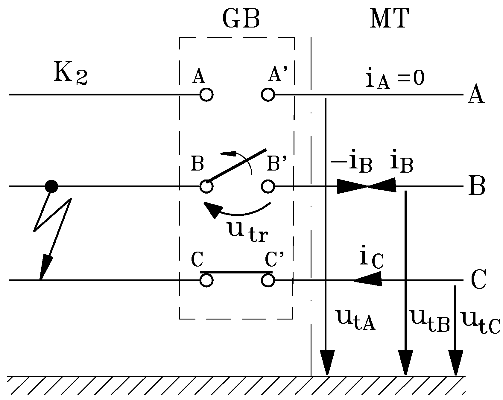
4.2.2. TRV Occurring at Insulated Two-Phase Short-Circuit Disconnection
The TRV calculation configuration for the moment when the short circuit has been eliminated is represented in
Figure 5. It corresponds as well to the second phase opening in the case of the insulated three-phase short-circuit disconnection.
The current interruption has been considered as result of injection on phase
B of the current
ik =
- iB, under the restriction:
and the TRV at the pole
B-B' is:
Figure 5.
Interruption of insulated two-phases short circuit.
Figure 5.
Interruption of insulated two-phases short circuit.
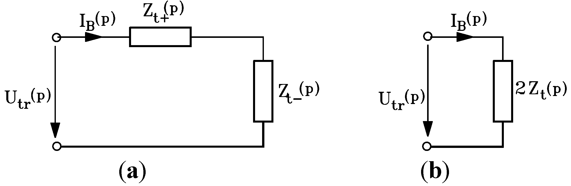
Applying the o.s.c. method, the TRV operational equation becomes:
Equation (29) allows the operational representation in
Figure 6a.
When
Zt+(p) = Zt-(p) = Zt(p), equation (29) is reduced:
with the operational circuit corresponding to
Figure 6b.
Figure 6.
Operational equivalent circuits: (a) TRV at insulated two-phases short-circuit disconnection, with Zt+(p) ≠ Zt-(p); (b) TRV at insulated two-phases short-circuit disconnection, with Zt+(p) = Zt-(p) = Zt(p).
Figure 6.
Operational equivalent circuits: (a) TRV at insulated two-phases short-circuit disconnection, with Zt+(p) ≠ Zt-(p); (b) TRV at insulated two-phases short-circuit disconnection, with Zt+(p) = Zt-(p) = Zt(p).
Applying the method of operational symmetrical components to determine the TRV which appears after the interruption of a short circuit fed by the main transformer represents an original contribution of the authors of this study. The method is suitable for application at the poles of any circuit breaker, for any eliminated fault type (fed by the main transformer or by the synchronous generator, as well), if the elements and configuration of the power network are known. The TRV which appears after the interruption of a short circuit fed by the transformer may be considered as an oscillation with the oscillation factor and the rising rate (RR) of TRV established by the transformer parameters: resistance, inductance, capacitance, and conductance.
5. Conclusions
Since the synchronous generator stator can flow via high asymmetrical short-circuit currents, which will not pass through zero many cycles after the fault appearance, in this paper, for shedding light on the proper moment when the generator circuit-breaker must operate, using the space phasor of the short-circuit currents, the time expression to the first zero passing of the three-phase short-circuit current fed by the generator has been determined. The manner in which the various factors influence the delay lasting of the first zero passing of the short-circuit current has been investigated.
This study demonstrated that, even though the phenomena produced in the electric arc at the terminals of the circuit-breaker are complicated and not completely explained, the concept of exergy is useful in understanding the physical phenomena. The appearance of an electric arc at the terminals of the circuit-breaker should not be necessarily be seen as a damaging phenomenon since if the electric arc would not appear the network embedded magnetic energy would be converted to a circuit electric field energy, leading further to high over-voltages in the network. Due to the arc exergy, the aperiodic pulsating component of the short-circuit current decreases very quickly, starting with the moment of contact separation. Since the alternating components with the pulsation ω are not influenced by this resistance increase, the output exergy of electric arc determines the first zero-passing of the phase currents and reduces the circuit-breaker stress. One could conclude that the embodied energy in the electric arc that appears in the generator circuit-breaker at the contacts opening has a favourable influence on the short-circuit current zero-passing, determining the decrease of time constant value Ta. We may conclude that, from the view point of the short-circuit current zero-passing, it is necessary that the generator circuit-breaker either has an important voltage drop in the arc (meaning a high electric arc resistance) or is able to interrupt the currents with an aperiodic pulsating component greater than the values stipulated by IEC Publication 60056 for the distribution circuit-breakers or those recommended by IEEE Std. C37.013-1997.
Modelling transient recovery voltage (TRV) of circuits has emphasized aspects with direct implication on commutation equipment. Thus, the o.s.c. method is able to be applied at the poles of any breaker, for any eliminated fault type, if the network configuration and elements are known. The rising rate (RR) of the TRVs occurring across the generator circuit breaker when the short circuits fed by the main transformer are eliminated can exceed the demands on standard distribution circuit-breaker. Hence, not only the IEC 62271-100 norm must be taken into consideration, but the capability to withstand high values of TRV and RR of TRV should be in compliance with IEEE Std. C37.013-1997.

 ,
, 