Mixing Performance of a Suspended Stirrer for Homogenizing Biodegradable Food Waste from Eatery Centers


Abstract
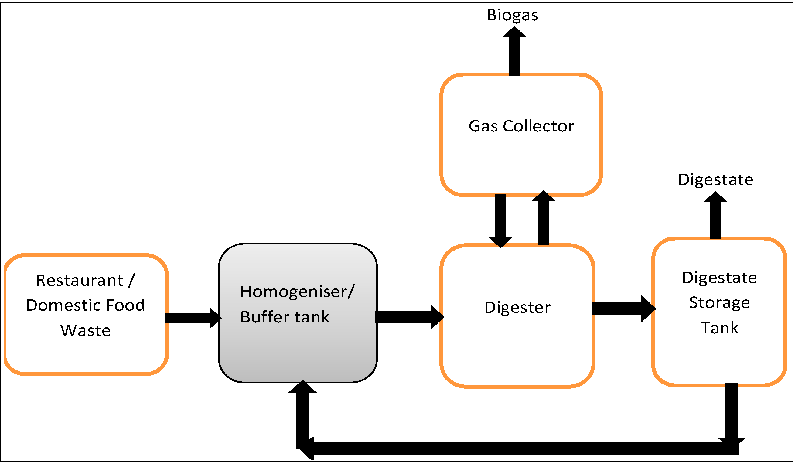
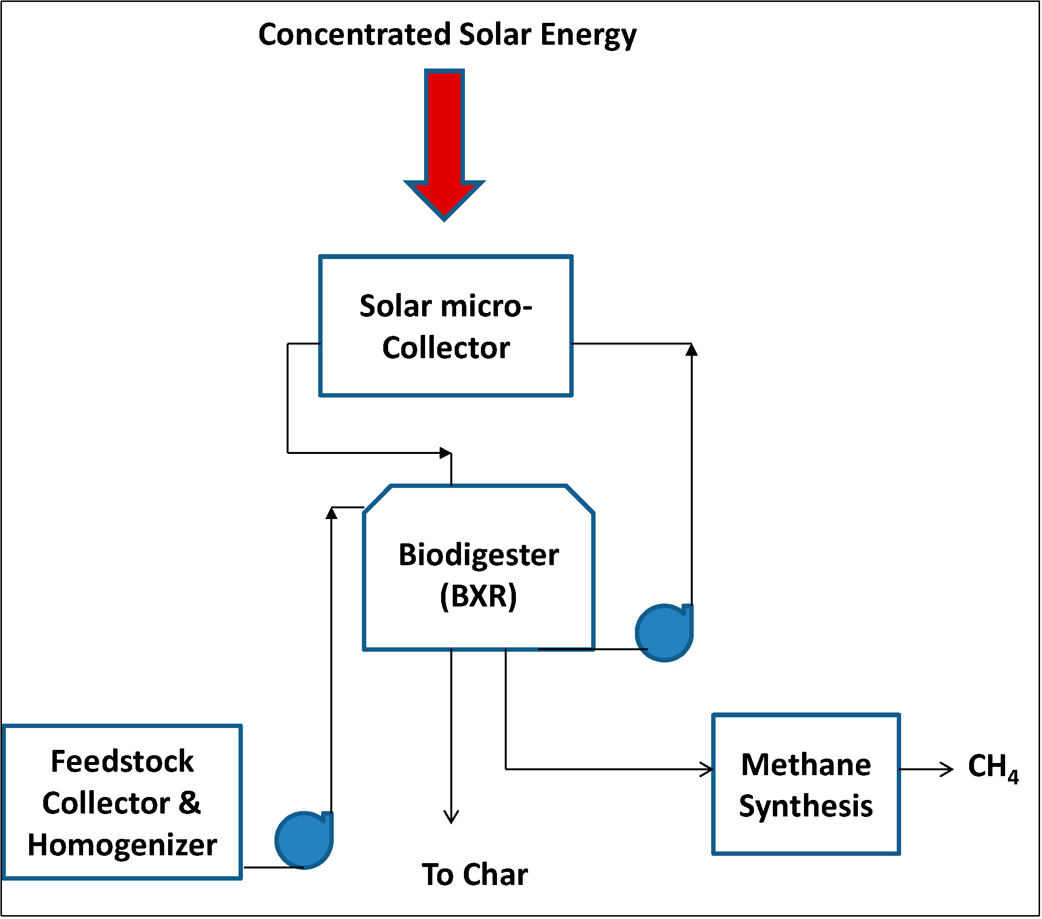
:1. Introduction

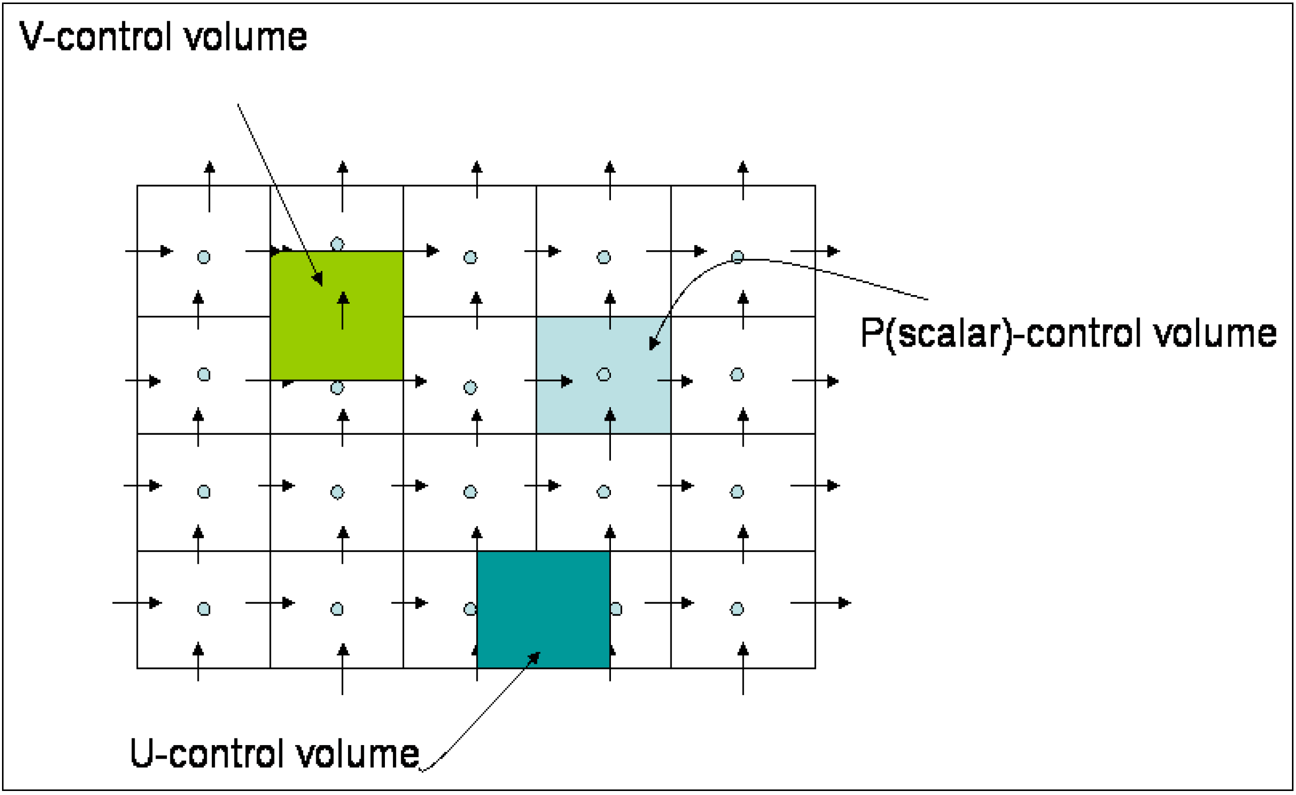
2. Finite Volume Formulation
2.1. Governing Equations of Viscous Food Waste


2.2. Formulation with Dirichlet Boundary Conditions


2.3. Numerical Simulation


| Fluid/Impeller Material | Density (kg/m3) | Specific Heat Capacity (J·kg−1·K−1) | Thermal Conductivity (W·m−1·K−1) |
|---|---|---|---|
| Carrot-orange soup | 1026 | 3880 | 0.596 |
| Stainless steel | 8000 | 500 | 16.3 |
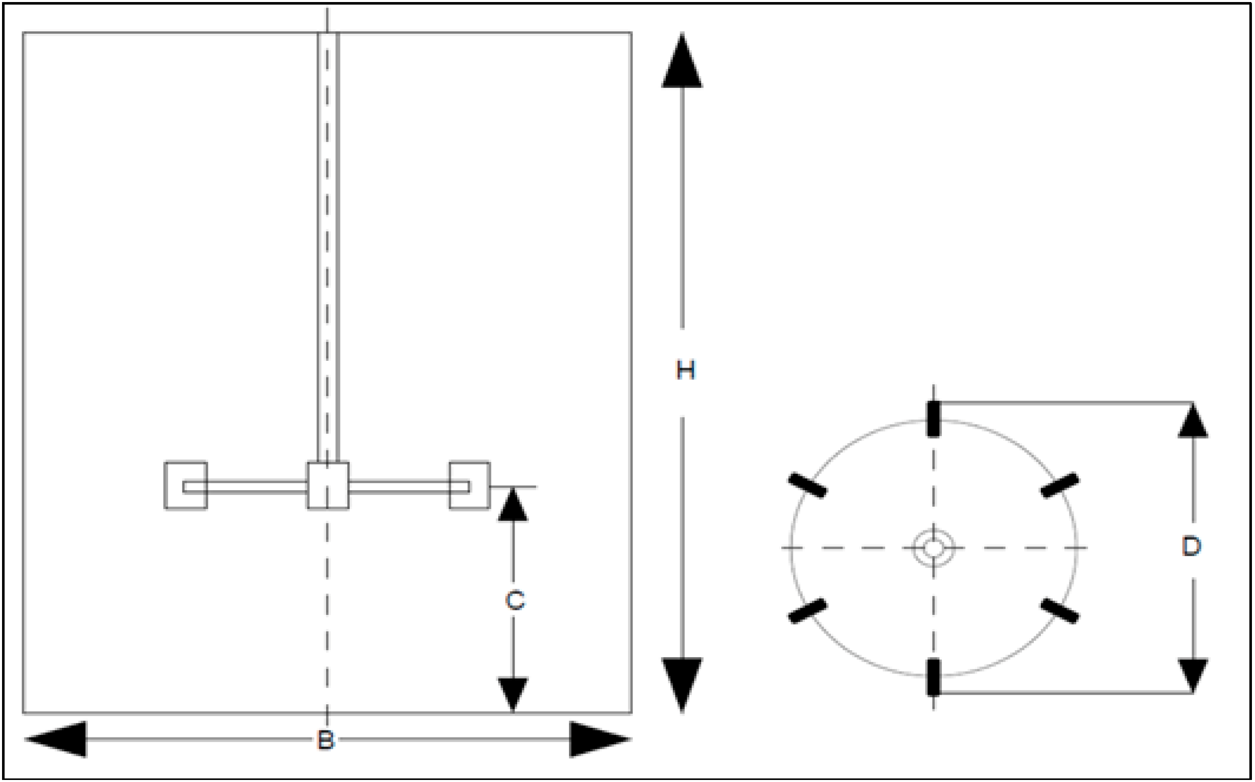
| Dimension | Value (m) |
|---|---|
| B | 0.300 |
| H | 0.375 |
| C | 0.125 |
| D | 0.016 |
3. Results and Discussion


4. Conclusions
Author Contributions
Conflicts of Interest
References
- Gray, D.; Paul, S.; Cara, P. Anaerobic Digestion of Food Waste, East Bay Municipal Utility District Report; East Bay Municipal Utility: Oakland, CA, USA, 2008. [Google Scholar]
- Zupančič, G.D.; Viktor, G. Anaerobic treatment and biogas production from organic waste. In Management of Organic Waste; Kumar, D.S., Bharti, A., Eds.; InTech: Rijeka, Croatia, 2012; pp. 1–28. [Google Scholar]
- Mata-Alvarez, J.; Macé, S.; Llabrés, P. Anaerobic digestion of organic solid wastes: An overview of research achievements and perspectives. Bioresour. Technol. 2000, 1, 3–16. [Google Scholar] [CrossRef]
- Kubaska, M.; Sedlacek, S.; Bodik, I.; Kissova, B. Food Waste as Biodegradable Substrates for Biogas Production Report; Institute of Chemical and Environmental Engineering, Slovak University of Technology: Bratislava, Slovak Republic, 2010. [Google Scholar]
- Ogedengbe, E.O.B.; Rosen, M.A. Electro-Kinetic pumping with slip irreversibility in heat exchange of CSP-powered bio-digester assemblies. Entropy 2012, 12, 2439–2455. [Google Scholar] [CrossRef]
- Gibson, T.; Smyth, M. Organic Waste Biodegradability Test Bio Methane Potential Method Report; Aqua Enviro: Wakefield, UK, 2007. [Google Scholar]
- Wang, J.Y.; Liu, X.Y.; Kao, J.C.; Stabnikova, O. Digestion of pre-treated food waste in a Hybrid Anaerobic Solid–liquid (HASL) system. J. Chem. Technol. Biotechnol. 2006, 3, 345–351. [Google Scholar]
- Harvey, P.S.; Greaves, M. Turbulent flow in an agitated vessel 2. Numerical-solution and model predictions. Trans. Inst. Chem. Eng. 1982, 4, 201–210. [Google Scholar]
- Luo, J.Y.; Issa, R.I.; Gosman, A.D. Prediction of impeller-induced flows in mixing vessels using multiple frames of reference. In Proceedings of the 8th Europe Conference of Mixing, Cambridge, UK, 21–23 September 1994; pp. 155–162.
- Mostek, M.; Kukukova, A.; Jahoda, M. Comparision of different techniques of modelling of flow field and homogenisation in stirred vessels. Chem. Pap. 2005, 6, 380–385. [Google Scholar]
- Pericleous, K.A.; Patel, M.K. The modelling of tangential and axial agitators in chemical reactors. Phys. Chim. Chem. Hydrodyn. 1987, 8, 105–123. [Google Scholar]
- Panton, R.L. Incompressible Flow, 2nd ed.; John Wiley & Sons: New York, NY, USA, 1996. [Google Scholar]
- Huang, W.; Li, K. CFD simulation of flows in stirred tank reactors through prediction of momentum source. In Nuclear Reactor Thermal Hydraulics and Other Applications; Post Guillen, D., Ed.; InTech: Rijeka, Croatia, 2013; pp. 135–153. [Google Scholar]
- Patankar, S.V. Numerical Heat Transfer and Fluid Flow; Hemisphere: Washington, DC, USA, 1980. [Google Scholar]
- Van Doormaal, J.; Raithby, G.D. Enhancements of the SIMPLE for predicting incompressible fluid flows. Numer. Heat Transf. 1984, 7, 147–163. [Google Scholar]
- Ogedengbe, E.O.B.; Naterer, G.F.; Rosen, M.A. Slip flow irreversibility of dissipative kinetic and internal energy exchange in microchannels. J. Micromech. Microeng. 2006, 16, 2167–2176. [Google Scholar] [CrossRef]
- Abdul Ghani, A.G. A Computer Simulation of heating and cooling liquid food during sterilization process using computational fluid dynamics. Assoc. Comput. Mach. N. Z. Bull. 2006, 2, 1–10. [Google Scholar]
© 2014 by the authors; licensee MDPI, Basel, Switzerland. This article is an open access article distributed under the terms and conditions of the Creative Commons Attribution license (http://creativecommons.org/licenses/by/3.0/).
Share and Cite
Babarinsa, O.; Ogedengbe, E.O.B.; Rosen, M.A. Mixing Performance of a Suspended Stirrer for Homogenizing Biodegradable Food Waste from Eatery Centers. Sustainability 2014, 6, 5554-5565. https://doi.org/10.3390/su6095554
Babarinsa O, Ogedengbe EOB, Rosen MA. Mixing Performance of a Suspended Stirrer for Homogenizing Biodegradable Food Waste from Eatery Centers. Sustainability. 2014; 6(9):5554-5565. https://doi.org/10.3390/su6095554
Chicago/Turabian StyleBabarinsa, Olumide, Emmanuel O.B. Ogedengbe, and Marc A. Rosen. 2014. "Mixing Performance of a Suspended Stirrer for Homogenizing Biodegradable Food Waste from Eatery Centers" Sustainability 6, no. 9: 5554-5565. https://doi.org/10.3390/su6095554