Article

Outcomes on the Spray Profiles Produced by the Feasible Adjustments of Commonly Used Sprayers in “Tendone” Vineyards of Apulia (Southern Italy)

Department of Agricultural and Environmental Science, University of Bari Aldo Moro, 70126 Bari, Italy
Sustainability 2016, 8(12), 1307; https://doi.org/10.3390/su8121307
Submission received: 19 September 2016 / Revised: 28 November 2016 / Accepted: 8 December 2016 / Published: 13 December 2016

Abstract

:
The objective of the research was to assess the outcomes on the spray patterns produced by the different feasible adjustments of two different air blast sprayers and one mist blower sprayer, commonly employed for treatments to Apulian “tendone” vineyards. The spray profiles of these machines and the respective refinements affected by the alteration of the available adjusting devices were evaluated using a test bench, suitably set up for calibrating the sprayers used inside such vines. The air blast sprayers, compared with the mist blower model, have a better chance to match the spray pattern and the canopy profile of the “tendone” vines. Furthermore, the left-right asymmetry of the spray profile is reduced only in the case of sprayers with two counter-rotating fans, under certain operating conditions. Conversely, the symmetry index worsens with the activation of the fan in the case of the air blast sprayer fitted with a single fan either with or without the air deflectors. The mist blower sprayer develops lower drawbacks, in terms of left-right asymmetry of the spray profile, even if the high “stiffness” of the spray profile makes this sprayer not particularly suitable to the changing needs of the canopy of the “tendone” vineyards. The obtained results, even if related to the analyzed sprayers, can represent an original base of reference to set up guidelines for the adjustment of sprayers used for treatments inside “tendone” vineyards, very useful for the officially authorized Apulian workshops to make sprayers inspection and calibration.

1. Introduction

The European Directive [1] pertinent to the sustainable use of pesticides states, among other topics, that pesticide application equipment in professional use must be inspected at regular intervals. In Italy the inspection of sprayers in use became mandatory after the adoption of the National Action Plan (NAP) that has incorporated into the national legislation the aforesaid EU Directive. According to the NAP, a more accurate and appropriate sprayer adjustment can be made from time to time in the official authorized workshops as a complement to the sprayer inspection [2]. The sprayer adjustment is then an operation that shall be made at the end of the functional inspection and it has to be carried out for each crop type and situation present on the farm, or at least for the most representative ones. A correctly adjusted sprayer guarantees that the spray mixture is addressed to the target, minimizing the risks for the environment (e.g., spray drift) and for consumers [3,4,5,6]. Conversely, in order to improve the efficiency of plant protection product (PPP) applications, the sprayer adjustment must be in agreement with the crop growth stage [7,8,9], the pesticide formulation [10,11,12], and the specific morphological characteristics and canopy patterns of the vineyard [13,14,15,16,17,18,19,20]. One of the main and crucial steps to adjust sprayers for bush and tree crops is represented by the evaluation of the spray profile, an operation carried out through suitable test benches that allow the verification of the spray plume matches the target canopy profile [21,22,23]. In this connection, the international standards which guide the sprayers’ inspections state that beyond the checks of the pressure drop, uniformity of the spray jet, and the flow rate measurements, further information may be supplied to the owner/operator, evaluating the vertical spray distribution through a vertical patternator, even if the test method and vertical patternator specifications are still under development [24]. A test bench purposely designed for the calibration of air blast and/or mist blower sprayers employed in Apulian “tendone” vineyards was set up at the Department of Agricultural and Environmental Science of the University of Bari Aldo Moro [25,26]. Apulia (Southern Italy) is Italy’s leading region for table grape production, with a yield of about 6.5 × 10⁸ kg, accounting for 61% of the total Italian production [27], and the most common vine training system used for table grapes is an overhead canopy supported by a trellis system, called “pergolato” or “tendone”. This trellis comprises a high stake at each vine with two orthogonal steel wires attached 1.7–1.8 m above ground level, and a grid of steel wires supporting the shoots. Each vine has a 1.2–1.4 m high trunk, with two branches and two fruit-bearing shoots per branch, aligned orthogonally or parallel to the grid.
Air-assisted sprayers fitted with an arc-shaped spray boom and mist blower sprayers fitted with air shear nozzles placed inside fixed or adjustable air diffusers, trailed by a narrow-track wheeled tractor [28], are usually used for PPP applications in these Apulian vines. Mist blower sprayers equipped with device for the electrostatic charge of the spray are also employed for the application of biostimulants for grape bunch growth [29,30].
A significant characteristic of the “tendone” vineyards is that only the lower side of the canopy is directly exposed to the spray during application of PPPs and then their action is strongly affected by the spatial distribution of the canopy (in terms of height, depth, leaf density, and discontinuity along the rows) and of the grape bunches [31]. Furthermore, a noticeable variability of the target (shape and volume of the canopy, spatial distribution of the bunches), due above all to the winter pruning operations (number and orientation of the fruit-bearing shoots) and green pruning operations (frequency, intensity and mode of leaf thinning) takes places within the table grapes “tendone” vineyards. Consequently, the sprayers must be adjusted so that the plume spray can penetrate correctly inside the canopy, avoiding non-uniform deposition, over dosage, off-target spray, and environmental pollution [32]. Finally, special care is ordered in terms of the procedure of PPP distribution, as no washing phase is included in the processing chain of table grapes from harvesting to commercialization. Therefore, it needs to avert volumes per hectare, as well as droplet populations and plume profiles likely to damage the appearance and the marketability of grapes (visible residues on grapes and/or residues levels however exceeding those allowed for each chemical employed). The adjustment, focused to the adaptation of the spray profile to the specific morphological and geometric characteristic of the “tendone” vineyards for table grapes, is then essential for the employed sprayers in order to maximize their performance and the effectiveness of the distributed PPPs [33].
Keeping in mind the aforementioned, the goal of this research has been to assess the outcomes on the spray patterns produced by the different feasible adjustments of two different air blast sprayers, basically distinct from each other for the characteristics of the fan and mist blower sprayers. The spray profiles generated by these machines, and the respective refinements affected by the alteration of the available adjusting devices, were evaluated using the aforementioned test bench, suitably set up for calibrating the sprayers employed in such vineyards.
The obtained results, even if related to the analysed sprayers, can represent an original base of reference to setup guidelines for the adjustment of sprayers used for treatments inside “tendone” vineyards for table grapes, which is very useful for the officially authorized Apulian workshops to conduct sprayer inspections and calibrations.

2. Materials and Methods

2.1. The Sprayers

The air blast sprayers are the Carrarospray “ATD800” (O.C.L.L. Manufacturer, Padua, Italy) and Carrarospray “ATP800” (O.C.L.L. Manufacturer, Padua, Italy) and the mist blower sprayer is a Carrarospray “NTF600” (O.C.L.L. Manufacturer, Padua, Italy) were considered for the evaluation of the spray profiles at the test bench and the pertinent outcomes produced by their feasible adjustments. These sprayers were chosen on the market among the typologies commonly used by Apulian growers for treatments inside “tendone” trained vines. The main technical characteristics were:
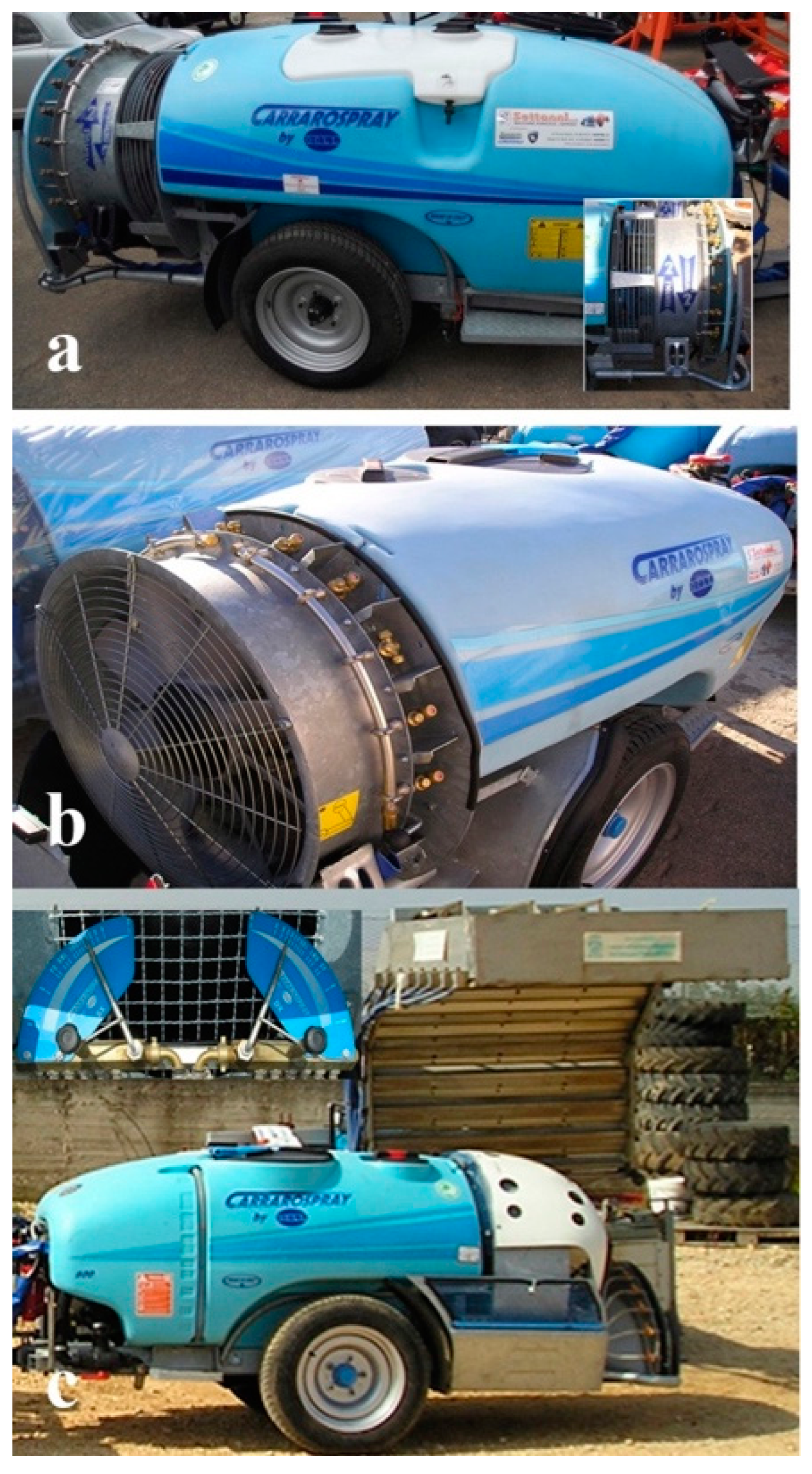
  • Carrarospray ATD800 (Figure 1a), equipped with a 600 L main tank and two counter-rotating axial fans (diameter 700 mm, fans axis height above the ground 730 mm) with an anterior intake. The first fan is counter-clockwise rotating, whereas the second one is clockwise-rotating. At 57 rad/s rotation speed of the tractor power take-off (PTO), beyond the idle position, the air flow rate was 54,000 m3/h at the highest gearbox ratio of the fans, and 42,260 m3/h as the lowest.
  • Carrarospray ATP800 (Figure 1b), equipped with a 600 L main tank and single axial fan (diameter 700 mm, counter-clockwise rotation, the fan axis height above the ground is 740 mm) with a rear intake. Air deflectors were mounted onto the output section of the fan, each one placed at the middle between two adjacent nozzles. The same gearbox ratios were available and at the 57 rad/s rotation speed of the PTO, the air flow rates were, respectively, 54,000 m3/h and 42,260 m3/h, beyond the idle position.
  • Carrarospray NTF600 (Figure 1c), equipped with a 600 L main tank and centrifugal fan (diameter 500 mm, counter clockwise rotation, the fan axis height above the ground is 740 mm); two adjacent spray head diffusers both having about 90° arch shape, each with six deflection nozzles (φ = 1.8 mm) in place. At the 57 rad/s rotation speed of the PTO, beyond the idle position, the air flow rate was 32,000 m3/h with the highest gearbox ratio of the fan, and 23,600 m3/h with the lowest. Furthermore, the overall flow rates discharged by the six simultaneously switched-on nozzles of each diffuser at the operative pressure of 0.3 MPa changed within the range 85–989 L/min and this adjustment took place by means of a control system constituted by a flow rate valve fitted with a wheel closely connected to a metal pointer moving on a graduated scale. Two separate control systems then allow the independent adjustment of the nozzle flow rates discharged by the two diffusers.
The two air blast sprayers were substantially similar and the main difference was that the first one was equipped with two counter-rotating fans, whereas the second one was equipped only with a single fan. All of the fans had, in turn, the same diameter, number of blades, and rotating speed; consequently, the air flow rates were exactly the same, taking into account that the air flow rate is usually calculated based on the strength of the fluid conditions at the fan intake [34,35]. Furthermore, for both of the sprayers, the arc-shaped spray boom was fitted with 5 + 5 double outlet rollover nozzle bodies, each one including a φ (diameter) 0.8 mm tip and a blank core on one end, and a φ 1.2 mm tip and a blank core on the other end (Figure 2). Furthermore, each spray tip had three open positions: the first one was obtained with the nozzle body placed in the same direction as the notch on the retainer cap (hereafter, the central position, i.e., 0°), the other ones, with detent at ±15°, respectively, from this direction.
Preliminary measurements included the flow rate of each nozzle of all the sprayers under tests, which was determined by the amount of liquid discharged during a working time of 60 s. Measurements were replicated three times for each sprayer setting (spray tip and core for the air blast sprayer, nozzles for the mist blower sprayer) and average values were assumed as reference [36]. Flow rates were calculated with a measurement error of less than ±2.5% of the true value [24].
The evaluations pertinent to the air blast sprayers were executed employing brand-new nozzles at the operative pressure of 2 MPa. Furthermore, according to the technical standard [24], it was also verified that at the aforementioned operative pressure, the flow rate of each nozzle did not deviate by more than 5% from the mean flow rate of the all nozzles mounted on the sprayer.
Conversely, the evaluations concerning the mist blower sprayer were executed, employing brand-new nozzles at the operative pressure of 0.3 MPa, pressure usually used by the Apulian vine growers for this typology of sprayer. This pressure value was measured at the manometer of the sprayer, placed on the plumbing system, upstream of the control systems. Additionally, in this case it was substantiated that, at this operative pressure, the flow rate of each nozzle did not deviate by more than 5% from the mean flow rate of all the nozzles mounted on the sprayer [24].

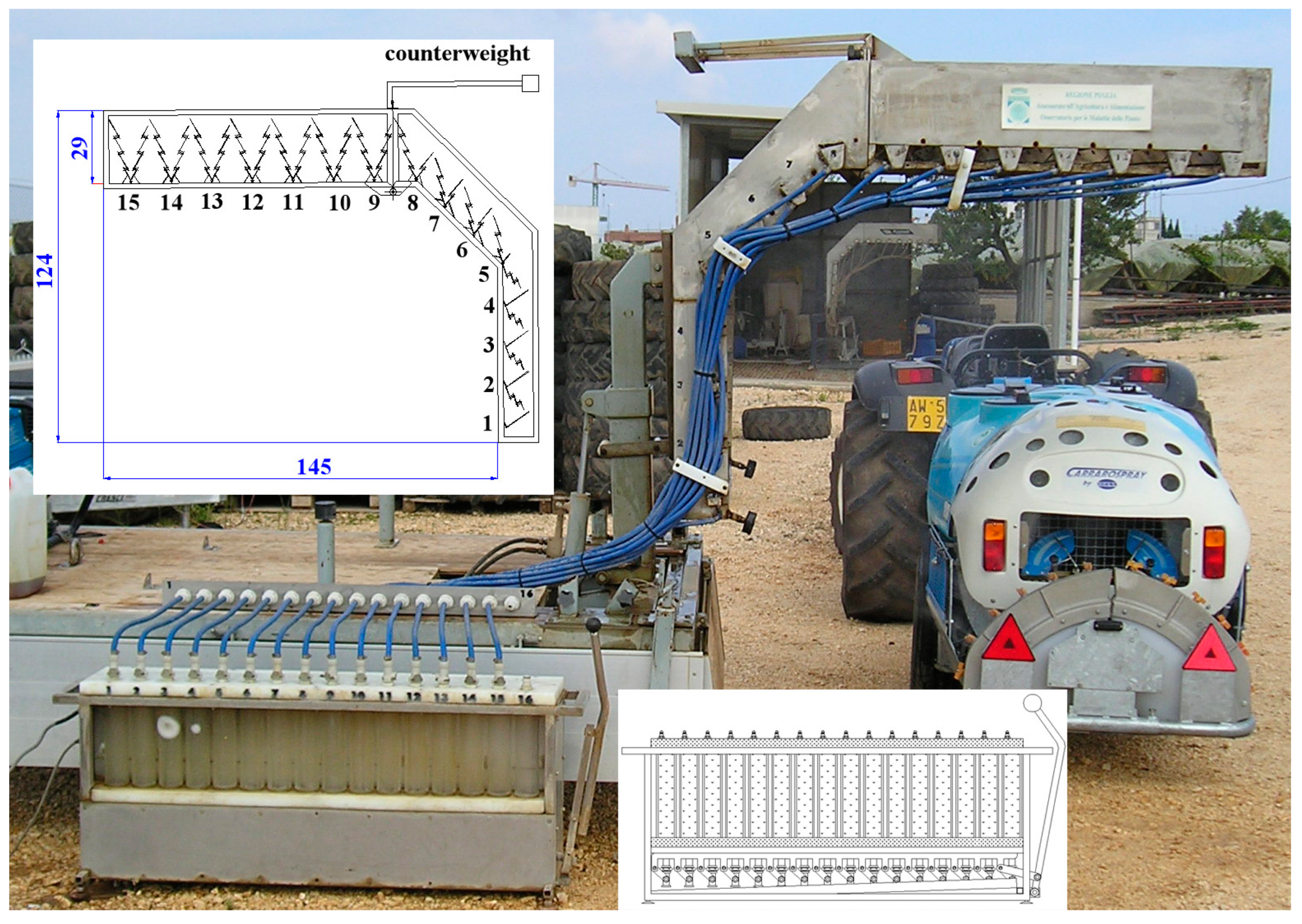
2.2. The Test Bench Used for the Assessment of the Spray Distribution Profiles

The test bench purposely set up for calibration of sprayers employed in “tendone” vineyards is substantially composed by a patternator arranged on a road trailer for ease of transport operations [25,26] (Figure 3). The patternator is a droplet interceptor consisting of a horizontal, oblique, and vertical metal profile so as to represent part of the “tendone” vineyard canopy, including part of the vine trunk. Its schematic section with the main sizes is depicted in Figure 3. The supporting frame is made with 20 × 20 × 2 mm stainless steel square tube, on which 15 intercepting tools are assembled. Each of these is formed by a set of thin steel sheets 1450 mm long assembled so that the intercepted water droplets slide along their surface, flowing into a stainless steel drip.
The fifteen drips, fixed with a mutual distance of 150 mm are connected by means of drain pipes to corresponding Plexiglas containers with a capacity of about 600 mL arranged inside a stainless steel measure test bench (Figure 3). This measure bench encapsulates the 16 Plexiglas containers (one is for back-up), each one, in turn, hydraulically linked to a corresponding pressure transducer to measure the volume of liquid inside it (Figure 3).
The pressure transducers (Druck PTX1400 (RS Components Ltd., Northants, UK)) have measuring range of 0–10 kPa and accuracy of ±0.15% (full scale). Sixteen ball valves, driven through a rod, allow at once the draining of the liquid in the containers at the end of each measure. Finally, an electric cable connects the measure bench to a laptop equipped with a data acquisition card (National Instrument DAQ-Card 700) and an ad hoc software allows the assessment of the amount of liquid inside each container and the real time evaluation of the distribution profile of the sprayer.
During the measurements, the sprayers were stationery and the patternator simulated the “tendone” canopy. Taking into account the average geometrical sizes of the Apulian “tendone” vineyards (vines planted with a layout of about 2.30 m × 2.30 m and a height of the canopy above the soil of about 1.90 m), the height of the horizontal trait of the patternator was placed at 1.90 m above the soil and the distance between axis sprayers and vertical trait was set at 1.15 m, corresponding to half the inter-row distance of the vineyard (Figure 4c). The recovery efficiency of the patternator was, on average, 73% [25]. Figure 4c shows an outline of the patternator obtained through three segments on which the locations of the interceptors are reported and numbered.
The spray profile was obtained considering the percentage of liquid Ii collected by every interceptor, calculated through Equation (1):
I i = Q i i = 1 15 Q i × 100
where Qi is the amount of liquid collected by the ith interceptor.
Furthermore, taking into account the positions of the interceptors and comparing them with the aforementioned average geometrical sizes of the Apulian “tendone” vineyards, the distribution patterns of both sides of the sprayers were combined to obtain an organic straightforward distribution diagram, as shown in Figure 4d. Practically, this total liquid profile was set up considering the amount of liquid Qi collected by the ith interceptor (ith = 1 to 11) of each side of the sprayer and adding the quantity of liquid Qi accumulated by the ith interceptor (ith = 12 to 15) of the left side to the corresponding one collected by the ith interceptor (respectively, ith = 15 to 12) of the right side, as reported in Table 1. Respecting the overlap of these interceptors, a new numbering of the interceptors has been then considered (Table 1 and Figure 4d). The resulting distribution pattern was obtained considering the percentage of liquid I i collected by every interceptor, calculated with Equation (2):
I i = Q i i = 1 26 Q i × 100
where Qi is the amount of liquid collected by the ith interceptor.
Conversely, the spray percentage symmetry index SI of the distribution pattern was determined by the following Equation (3) [37]:
S I = i = 1 15 | I i , r I i , l | n
where Ii,r and Ii,l are the percentage amount of liquid collected in the ith interceptor, respectively placed on the right and left of the sprayer.

2.3. The Experimental Design

The experimental design of the air blast sprayers took into account the combinations of different feasible adjustments which included the inclination of the nozzle bodies, the disc hole of the spray tips, and the air flow rates. The inclination of the nozzle bodies was measured with respect to the sprayer retailer’s arrangement (central position, 0°). Starting from this basic position the two opened positions were considered, available by the rotation of the nozzle body, respectively clockwise (+15°) and counter clockwise (−15°), for an observer looking at it from the rear of the sprayer (Figure 4a). For both the sprayers, the evaluations of the distribution profiles at the patternator, were carried out considering only the 4 + 4 nozzles, from 1–4 starting from the topmost nozzle, indicated with “l” or “r” according as placed on the left- or the right-hand side of the machine, at an operative pressure of 2 MPa (Figure 4c).
In detail, the 18 combinations obtained through the following adjustments were considered for the Carrarospray ATD800:
  • Two spray tips:
    • φ 0.8 mm tip and blank core;
    • φ 1.2 mm tip and blank core;
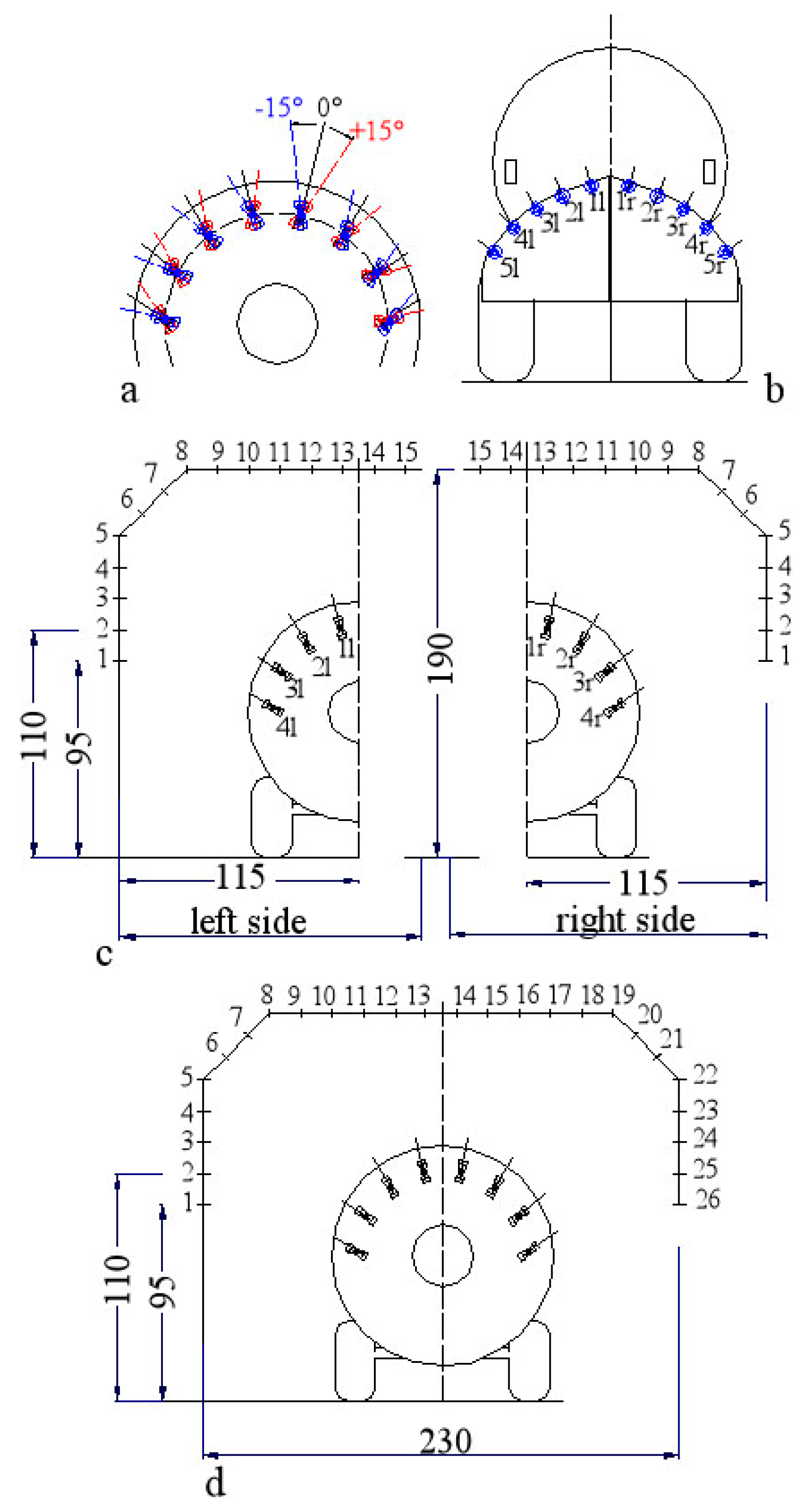
  • Three angular positions of spray tips with 4 + 4 nozzles simultaneously switched on:
    • A: central position (0°);
    • B: counter-clockwise rotation (−15°) of the four nozzle bodies placed on the right side and clockwise rotation (+15°) of the four nozzle bodies placed on the left side;
    • C: clockwise rotation (+15°) of the four nozzle bodies placed on the right side and counter-clockwise rotation (−15°) of the four nozzle bodies placed on the left side (Figure 3a);
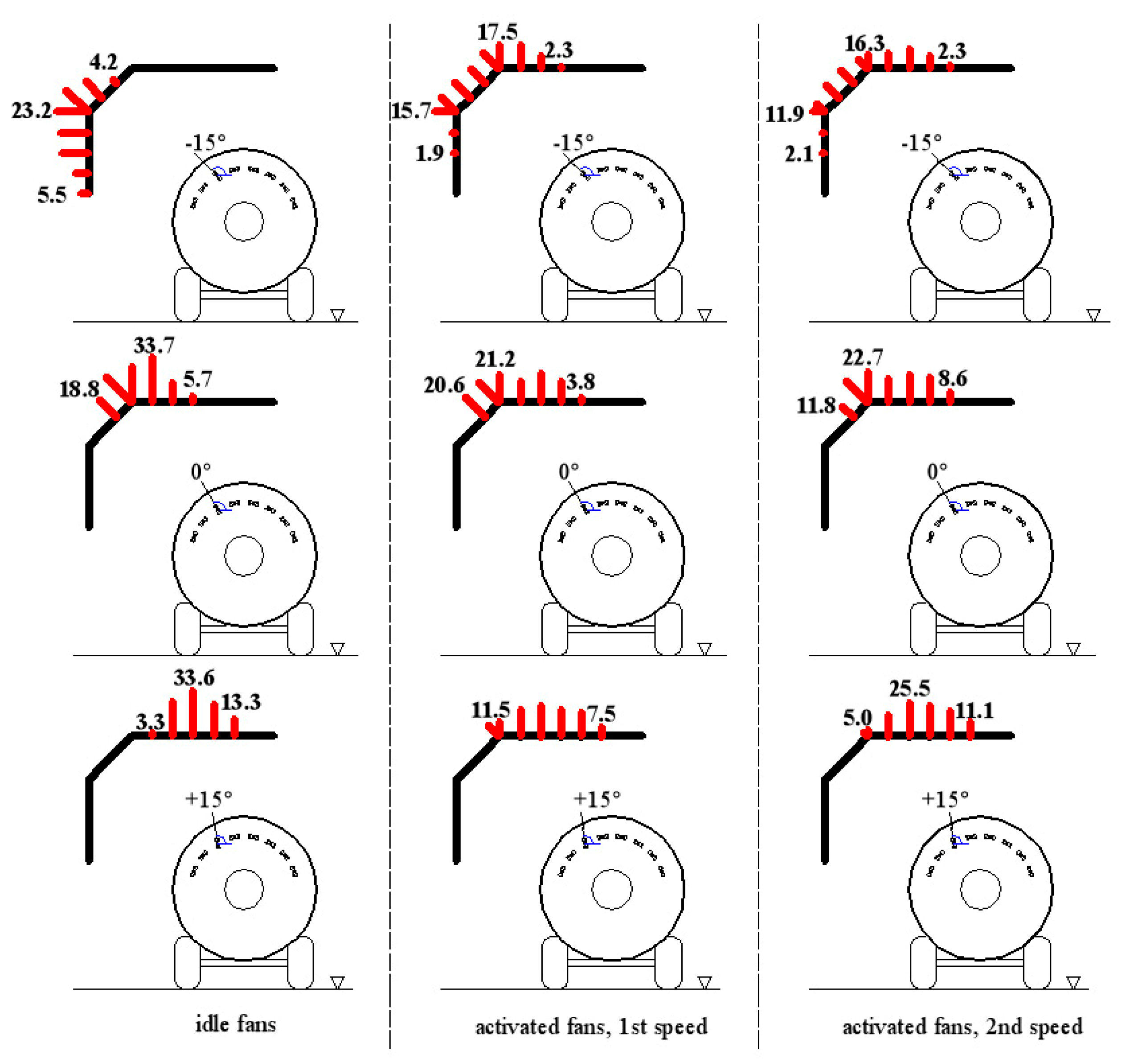
  • Three air flow rates:
    • 0 m3/h (idle fan);
    • 42,120 m3/h (fan first speed);
    • 54,000 m3/h (fan second speed).
Conversely, eight combinations were analysed for the Carrarospray ATP800, produced by the means of the following adjustments:
  • Two spray tips:
    • φ 0.8 mm tip and blank core;
    • φ 1.2 mm tip and blank core;
  • Two angular positions of spray tips with 4 + 4 nozzles simultaneously switched on:
    • B: counter-clockwise rotation (−15°) of the four nozzle bodies placed on the right side and clockwise rotation (+15°) of the four nozzle bodies placed on the left side;
    • C: clockwise rotation (+15°) of the four nozzle bodies placed on the right side and counter-clockwise rotation (−15°) of the four nozzle bodies placed on the left side (Figure 4a);
  • Two air flow rates:
    • 0 m3/h (idle fan);
    • 54,000 m3/h (fan, second speed).
Furthermore, in order to evaluate the effectiveness of the air deflectors on the Carrarospray ATP800, sprayer, the aforementioned eight combinations were carried out either with these devices mounted, as required by the manufacturer, and without them.
The idle fan was considered as further operative condition, taking into account that several vine growers carry out agrochemical treatments to “tendone” vineyards without air assistance in the early phenological stage, due to the close range between the target and the nozzles.
The Carrarospray ATD800 and Carrarospray ATP800 alike, for each of the aforementioned combinations, the spray profiles were assessed considering (Figure 4c):
  • each spray tip, one by one switched on; and
  • the spray tips placed on each side of the machine simultaneously switched on.
The experimental design of the Carrarospray NTF600 took into account the combinations of different feasible adjustments, which included the nozzle flow rates and the air flow rates. The evaluations of the spray profiles at the patternator, were carried out considering only the 5 + 5 nozzles, from 1–5 starting from the topmost nozzle, indicated with “l” or “r” according as placed on the left- or the right-hand side of the machine, at an operative pressure of 0.3 MPa (Figure 4b).
In detail, the four combinations obtained through the following adjustments were considered:
  • Two air flow rates:
    • 23,600 m3/h (fan first speed);
    • 32,000 m3/h (fan second speed).
  • Two nozzle flow rates on the average discharged by both the diffusers:
    • 4.10 L/min (Qmb1);
    • 9.20 L/min (Qmb2).
Qmb1 was selected to evaluate the outcomes on the spray distribution profile produced by the minimal overall feasible nozzles flow rate (extreme operative condition). Conversely, the highest nozzle flow rate Qmb2 was chosen taking into the considered the inter-row length (2.3 m), the volume rate V (400 L/ha), and the forward speed v (1.67 m/s) on the average employed by the Apulian wine-growers for treatments in “tendone” vineyards for this sprayer typology. Therefore Qmb2 was calculated with the following basic Equation (4):
Q mb 2 = V × v × i 167 = 400 × 1.67 × 2.3 167 = 9.20   L / min
The evaluations at the patternator were executed only considering the retailer’s nozzles arrangement because the sprayer did not allow other quick and easy changes of their angular positions.
For each combination, the spray profiles were evaluated considering:
  • each nozzle, one by one switched on; and
  • the nozzles placed on each side simultaneously switched on.
For all the sprayers under test, the assessments at the patternator pertinent to each combination were replicated three times and average values were assumed as reference. Naturally, the patternator was positioned first at the left, and then at right, of the stationery sprayers.

3. Results and Discussion

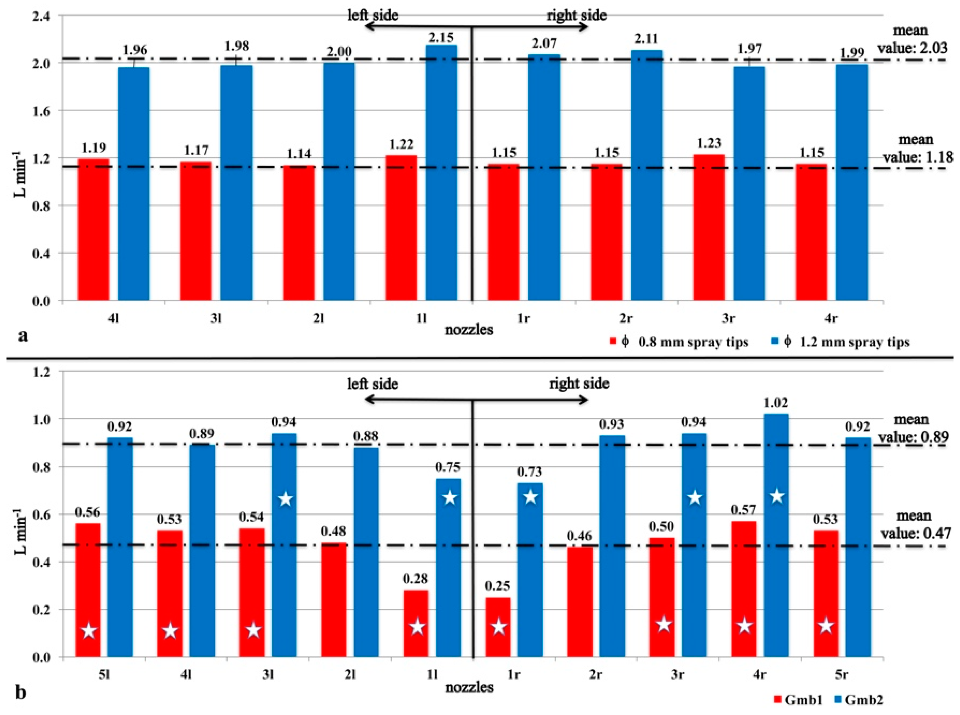
3.1. Measure of the Nozzle Flow Rate

The results concerning the flow rates discharged by the nozzles of the Carrarospray ATD800 at the operative pressure of 2 MPa are depicted in Figure 5a. All of the nozzles used for the assessment of the distribution profiles at the patternator complied with the respective standard because none of the single flow rates disagree with the average values by more than 5%. These operative conditions also took place for the nozzles employed on the Carrarospray ATP800 at the aforementioned working pressure. The effective mean and overall flow rates discharged by the nozzles mounted on the air blast sprayers under test are reported in Table 2.
On the other hand, some drawbacks were pointed out during the evaluations of the flow rates discharged by the nozzles of the Carrarospray NTF600, caused by discrepancies among the measured flow rates and the corresponding ones outlined by the metal pointer on the graduated scale of the control system for both the diffusers. Furthermore, once again for both of the diffusers, the modification of the number of the switched-on nozzles caused fluctuations of the operative pressure and, therefore, adjustment of the flow rate valve was necessary to restore the pressure at 0.3 MPa. Nonetheless, the results pertinent to the flow rates discharged by the nozzles of the NTF600 are shown in Figure 5b. Considering the operative condition connected to Qmb1, at 0.3 MPa, the mean nozzle discharged flow rate was 0.47 L/min and all the nozzles, except 2l and 2r, marked with a star in Figure 4b, did not comply with the standard because they diverged from this value by more than 5%. The effective overall nozzles flow rate corresponding to Qmb1 was then 4.70 L/min. Instead, taking into account the operative condition corresponding to Qmb2, at 0.3 MPa, the mean nozzle discharged flow rate was 0.89 L/min and also in this case several nozzles (3 l, 1 l, 1 r, 3 r,4 r), marked with a star in Figure 4b, did not comply with the standard. The effective overall nozzles flow rate corresponding to Qmb2 was then 8.92 L/min. In conclusion, the flow rates produced by the nozzles of each diffuser of the tested mist blower sprayer have never been uniform in any selected operative condition.

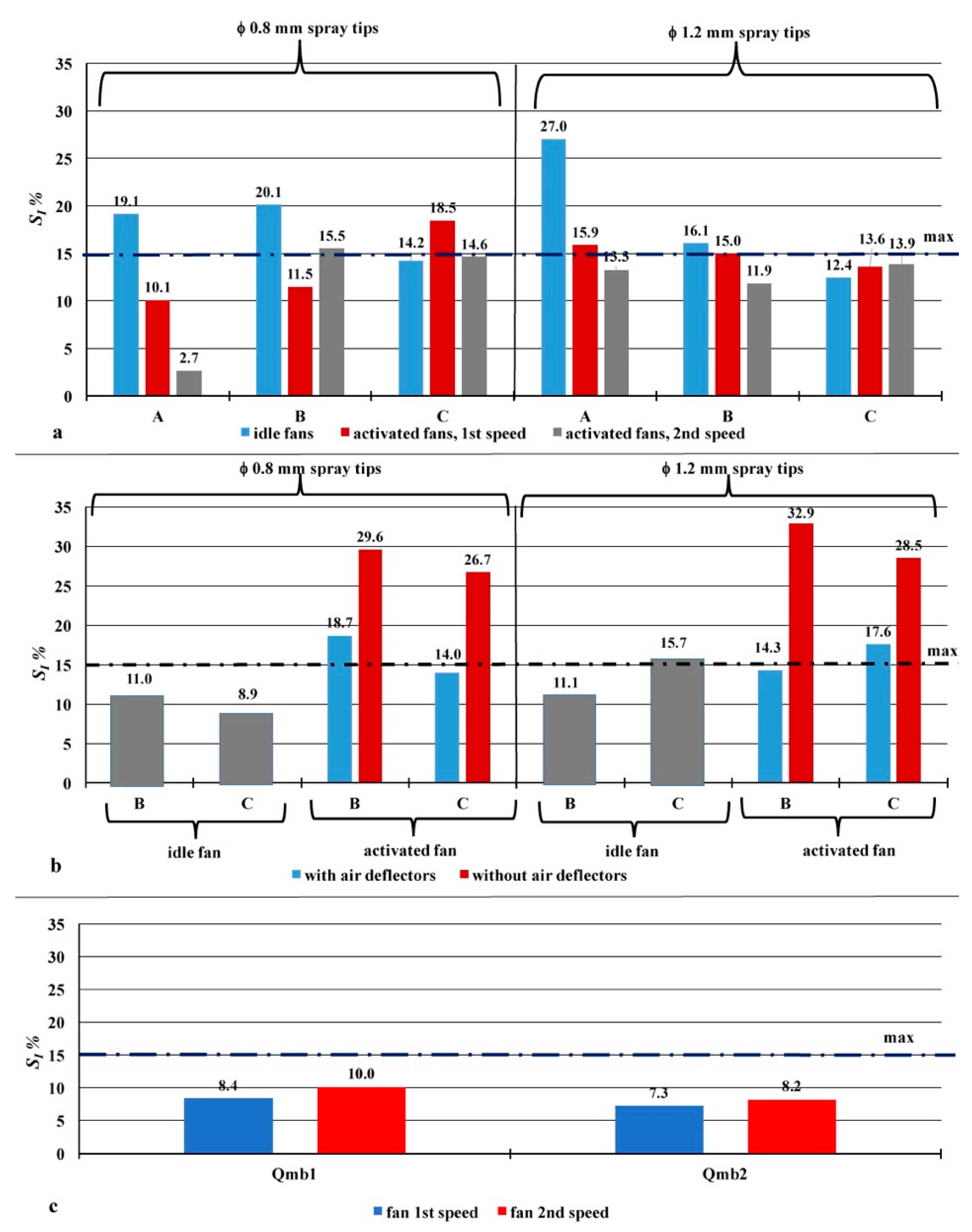
3.2. Symmetry Index of Distribution Diagrams

It is known that the left-right asymmetry of the spray patterns represents a drawback for the traditional air blast sprayers fitted with only one axial fan and that the manufacturers modify the rotation of the nozzles, or by the addition of tower diffusers, or deflectors to straighten the air flow, or a second counter-rotating fan. It is also known that this latter solution is, among others, the most effective but, at the same time, the most expensive in terms of purchasing and operating costs of the sprayer. Tests performed at the patternator confirmed that the spray symmetry index SI concerning the Carrarospray ATD800 (two counter-rotating fans) can decrease under certain operating conditions or increase under other ones (Figure 6a).
In particular, the index SI significantly decreases with the activation of the fans and/or the increase of their rotation speed, with the nozzle bodies placed at the central position (0°): with the φ 0.8 mm tips, SI is 19.1%, considering the idle fans, while reducing to 10.1%, or even 2.7%, with the activated fans, respectively, at the first speed (42,260 m3/h) or at the second speed (54,000 m3/h). Conversely, with the φ 1.2 mm tips, SI is 27.0% with the idle fans, while reducing to 15.9% or 13.3% when activating the fans, respectively, at the two selected speeds (Figure 6a). The other operative conditions, obtained by combining the selected angular position of the nozzle bodies and tip hole diameters with the switched-on fans, differently affects the boost or lowers the symmetry index even if, in large part, the SI values are close or a little higher than the 15% limit, fixed by the Italian technical standard for the adjustment at the patternator of the sprayers in use [32].
The indices SI pertinent to the Carrarospray ATP800 (single axial fan) are close or lower than the fixed limit when the fan is in the idle position. Considering the B case, i.e., –15° rotation of the nozzle bodies placed on the right side and +15° rotation of the nozzle bodies on the left side of the sprayer, the SI index is, respectively, 11.0% with the φ 0.8 mm tips and 11.1% with the φ 1.2 mm tips (Figure 6b). These values are lower than the corresponding ones registered with the Carrarospray ATD800: 20.1% (+83%) with the φ 0.8 mm tips and 16.1% (+45%) with the φ 1.2 mm tips (Figure 6a). These divergences are probably due to the different locations, reciprocal space, and basic orientation of the nozzle bodies on the arc-shaped booms of the two sprayers. Taking into account the C case, i.e., +15° rotation of the nozzle bodies placed on the right side and –15° rotation of the nozzle bodies located on the left side of the sprayer, and considering once again the fan in the idle position, the SI index pertinent to the ATP800 becomes, respectively, 8.9% with the φ 0.8 mm tips and 15.7% with the φ 1.2 mm tips (Figure 6b). This is probably due the same aforementioned reasons. Additionally, these values are not comparable with the corresponding ones registered with the Carrarospray ATD800: 14.2% (+60%) with the φ 0.8 mm tips and 12.4% (−21%) with the φ 1.2 mm tips (Figure 6a).
The activation of the fan of the ATP800 fitted with the air deflectors produces a general worsening of the spray symmetry; in the B case, considering the φ 0.8 mm tips, the SI index is 18.7%, with a rise of +70% compared with the corresponding idle position; conversely, taking into account of φ 1.2 mm tips, the SI index is 14.3%, with a rise of +29% against the corresponding idle position (Figure 6b). However, the turning effect of the air stream causes a dramatic deterioration of the spray symmetry when the ATP800 is unsupplied by the air deflectors. With these operative condition, in the B case, SI is 29.6% (gain +169% against the idle position) with φ 0.8 mm tips and 32.9% (gain +196% against the idle position) with φ 1.2 mm tips. An analogous situation take place in the C case: SI is 26.7% (rise +200% against the idle position) with φ 0.8 mm tips and 28.5% (rise +81% against the idle position) with φ 1.2 mm tips (Figure 6b). Therefore, for the typology of air blast sprayers fitted with a single axial fan, provided or not with air deflectors, the right-left spray asymmetry correction requires adjustments basically aimed to counter the turning effect of the air stream generated by the fan and the adjustment at the patternator is very crucial for these sprayers.
Finally, the SI indices pertinent to the NTF600 are well below the fixed limit in every examined operative condition. The lowest SI values were obtained using the highest nozzle flow rate: 7.3% with 23,600 m3/h of the air flow rate and 8.2% with 32,000 m3/h. These indices are very similar, having a percentage deviation of 12%, (Figure 6c). Additionally, with the lowest nozzle flow rate the symmetry indices are satisfactory. This behavior is probably caused by the canalization of the air stream through the diffusers that allows equalizing the spray plume, even in the presence of the aforementioned nozzles’ flow rate irregularities.

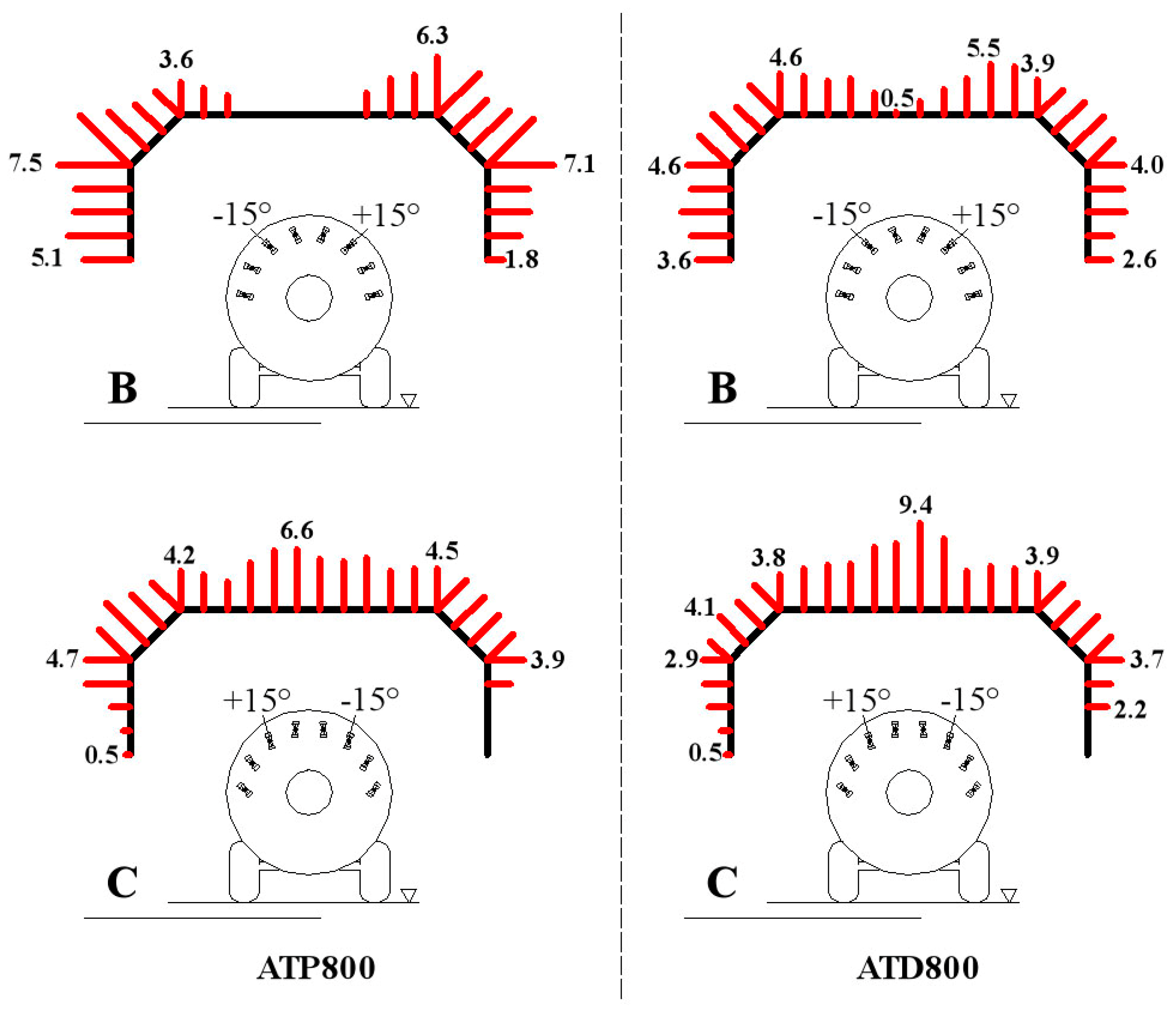
3.3. Outcomes on the Spray Profile Due to Angular Positions of Nozzles and Their Placement on the Boom

Each nozzle of the air blast sprayers according to its location on the arc shape boom and the adopted angular position of the nozzle body is able to spray a specific position of the patternator, which corresponds to a well-defined area of the target, during the agrochemical treatments. Almost all of the target portions of “tendone” vineyards can be sprayed by modifying the angular positions of the second and third nozzle bodies pertinent to the right and left sides of both of the sprayers (Carrarospray ATD800 and Carrarospray ATP800). For example, the outcomes produced by the change of the available angular positions of the second nozzle body placed on the left side of the ATD800 are depicted in the graphs of Figure 7, obtained through Equation (1).
Furthermore the distribution profiles are significantly different according to whether the fan (Carrarospray ATP800) or fans (Carrarospray ATD800) are switched on or deactivated (idle). The outcomes due to the combinations of the angular positions of the nozzle bodies and their location on the arc shape booms strictly affect the quickness/simplicity to match the spray pattern with the canopy profile, as well as the risk to nourish the "off-target" losses. This quickness/simplicity to adjust the spray profile is also connected both to the geometric characteristics of the “tendone” canopy and the technical features of the air blast sprayers [32].
The main geometric characteristics of the “tendone” canopy can be summarized as follows: the vegetative-productive area is placed on a horizontal plane at about 1.80–2.00 m above the soil level; the target width is equal to the inter-row distance (2.00–2.50 m), or double in the case of treatments on alternate rows; the fruit-bearing area is placed over the entire width of the inter-row (plants with four fruit-bearing shoots orthogonally aligned to the grid) or arranged to the sides of the inter-row (plants with two, three, or four fruit-bearing shoots parallel aligned on the grid). Conversely, even if the air blast sprayers are fitted with a high number of nozzles, only 3 + 3, or 4 + 4 nozzles, starting still from the topmost ones, are usually simultaneously switched on for treatments to the canopies of “tendone” vines. The sprayers adjustment must then be carried out, duly selecting the angular positions of these nozzle bodies so that each working tip can spray towards the right intercepting tools of the patternator (Figure 4c). Nonetheless, the outcomes on the spray profiles produced by the adjustments carried out on the sprayers under test highlighted that the few available angular positions of the nozzle bodies made the calibration process arduous, especially in the case of 3 + 3 switched on nozzles. The use of nozzle bodies that allow a greater number of available angular positions would certainly facilitate the adjustment of the sprayer using the patternator.
The risk to nourishing the “off-target” losses is linked to the amount of liquid collected by the intercepting tools placed downwards (1 and 2 in Figure 4c), i.e., those ones located at 95–110 cm above the soil and then well below the canopy and the productive area of the “tendone” vines [28]. The assessment of the spray profiles produced by both the air blast sprayers pointed out that, in a greater or lesser proportion, the nozzles 4l and 3l (when −15° rotated) and 4r and 3r (when in +15° rotated) (Figure 4c) would be responsible for the “off-target” losses.
Some examples of the total liquid profiles measured at the patternator, obtained through Equation (2) and pertinent to the B and C cases, are reported in Figure 8 for Carrarospray ATP800 and Carrarospray ATD800, respectively. In particular, they were set up considering the φ 1.2 mm tips for both the sprayers, the activated fan for the Carrarospray ATP800, equipped with the air deflectors, and the activated fans, at the second speed, for the Carrarospray ATD800.
The outcomes on the spray profiles obtained with the B configuration, i.e., −15° rotated the nozzle bodies placed on the right side and +15° rotated the nozzle bodies on the left side of the sprayer, are different for the two sprayers. In particular, further to the Carrarospray ATP800, a significant amount of liquid is shown on the vertical traits of the patternator, on average 45.2% of the total intercepted by the patternator; whereas only the 33.1% is highlighted on the oblique traits and 21.7% on the horizontal trait (Figure 8). Furthermore, on this horizontal trait the spray has been collected only by the interceptors close to the oblique traits as the ones from 11–15 are set to zero (Figure 4d and Figure 8). With reference to the Carrarospray ATD800, the spray distribution among the different traits of the patternator is almost uniform: 34.3%, 27.2%, and 38.5% are the percentage of allocation of the total collected liquid among the vertical, oblique, and horizontal traits, respectively. Both of the spray profiles show amounts of liquid collected by the intercepting tools placed downwards, below the canopy and productive area of the “tendone” vine (1, 2, 25, and 26 in Figure 4d). As already said, this amount can nourish the risk of “off-target” losses; nevertheless, it is also plausible that a fraction of this off-target loss goes on the canopy of the adjacent inter-rows and then it does not represent a ground loss [33].
The trend of the spray profiles of the two sprayers, concerning the C configuration, i.e., +15° rotated nozzle bodies placed on the right side and −15° rotated nozzle bodies located on the left side of the sprayer, are comparable even if the respective amount of spray along the traits of the patternator are different (Figure 8). Both the distribution profiles highlight a noticeable lowering of the quantity of spray along the vertical traits of the patternator, on average 18.1% for the Carrarospray ATP800 and 14.6% for the Carrarospray ATD800 of the total. Again, it should increase the foliar spray deposition in the adjacent rows, when not intercepted by the grape bunches. Along the oblique traits, the spray is, on average, 27.9% for Carrarospray ATP800 and 22.8% for Carrarospray ATD800 of the total and, finally, along the horizontal trait, the quantity of liquid is respectively 54.0% (Carrarospray ATP800) and 62.6% (Carrarospray ATD800).
The total liquid profiles obtained at the patternator, such those of Figure 8, must be compared with the “reference profiles”, suitably set up according to the information provided by the owner/user, the only of aware of the growth characteristics of the canopy of the “tendone” vineyard interested by the sprayer to be adjusted [32]. Each “reference profile” is strictly connected to the specific target of the pesticide treatment and then it must be developed on the strength of the physical features of the “tendone” vineyard; that is, the spatial layout of the branches and the fruit-bearing shoots per branch, and its morphological characteristics, such as the minimum and maximum heights of the vegetation, the depth of the canopy, the minimum and maximum heights of the fruit-bearing area, the width of the fruit-bearing area, and so on [33]. These morphological characteristics appreciably change in the different phenological phases and then it is necessary to assess the “reference profile” with respect to the vegetative and productive profile of the vineyard in the most critical periods, in terms of intensity and danger of pests [11].
The spray profiles at the patternator produced by the 5 + 5 nozzles simultaneously switched on of the Carrarospray NTF600 pointed out a substantial uniformity of distribution, also confirming the aforementioned contracted right-left asymmetry for all of the analysed combinations. Clearly, then, the positive action of the airstream, channeled by the diffusers that rectify the non-uniform nozzles’ flow rates emerges. For example, the spray profile pertinent to the combination obtained considering the fan second speed (32,000 m3/h) and the Qmb2 nozzle flow rate (4.5 L/min) is depicted in Figure 9a.
Conversely this diagram highlights amounts of liquid collected by the intercepting tools placed downward (1 and 2 in Figure 4c) that are linked to “off-target” losses, and this drawback has suggested to search for the responsible nozzles among the 5 + 5 switched on. Therefore, the spray diagrams produced by each nozzle, one by one switched on, allow for affirmation that the nozzles 5l and 5r (Figure 4b) would be responsible of the “off-target” losses and the leakage of mixture during the treatments. As a consequence, the employment of 4 + 4 nozzles or at most 3 + 3 nozzles simultaneously switched on, would eliminate these losses as shown, respectively, in Figure 9b,c.

4. Conclusions

The foregoing remarks relate to the outcomes produced by the feasible adjustments of the sprayers under test. Nevertheless, they allow the formulation of some general observations that can be expanded to similar typologies of sprayers when used for treatments to the canopy of “tendone” vineyards.
Air blast sprayers:
  • compared with the mist blower model, have a better chance to match the spray pattern with the canopy profile of the “tendone” vines;
  • the left-right asymmetry of the spray profile is reduced only in the case of sprayers with two counter-rotating fans, operating at high speed, under certain operating conditions;
  • the symmetry index is influenced by the hole size of the nozzles and their angular positioning;
  • the symmetry index worsens with the activation of the single fan either with or without the air deflectors even if, in this last case, the deterioration produced by the turning effect of the air stream is very marked;
  • regardless of the interference of the sprays, the two lower-positioned nozzles, when rotated outward, would be potentially responsible for the off-target losses; and
  • the optimum air blast sprayer for treatments to “tendone” vineyards should include two counter-rotating fans and 3 + 3 simultaneously switched-on nozzles, mounted on arc-shaped booms having a higher radius of curvature.
Mist blower sprayer:
  • it develops lower drawbacks, in terms of left-right asymmetry of the spray profile;
  • the high “stiffness” of the spray profile, which cannot be corrected because there are no devices for quick and easy adjustments, making this sprayer not particularly suitable to the changing needs of the canopy of the “tendone” vineyards;
  • the use of 5 + 5 simultaneously switched on nozzles— the currently adopted solution—increases the “off target” losses caused, in particular, by the outer nozzle (left and right); and
  • the optimum mist blower sprayer for treatments to “tendone” vines should include the possibility to adjust the spray profile.

Acknowledgments

The Author wish to thank Carmine Gidiuli, Vito Marzano and Davide Sfregola of the Department of Agricultural and Environmental Science of the University of Bari Aldo Moro, for their helpfulness and commitment in conducting the experimental tests.

Conflicts of Interest

The author declares no conflict of interest.

References

  1. Establishing a Framework for Community Action to Achieve the Sustainable Use of Pesticides. Available online: http://eur-lex.europa.eu/LexUriServ/LexUriServ.do?uri=OJ:L:2009:309:0071:0086:en:PDF (accessed on 8 December 2016).
  2. Herbst, A. SPISE Guidelines on How to Make Sprayer Adjustment at the Workshop as an Addition to the Functional Inspection of the Field Crop Sprayers. In Proceedings of the Fifth European Workshop on Standardised Prodedure for the Inspection of Sprayers (SPISE 5), Montpellier, France, 15–17 October 2014.
  3. Balsari, P.; Oggero, G.; Marucco, P. Proposal of a Guide for Sprayers Calibration. In Proceedings of the Second European Workshop on Standardised Prodedure for the Inspection of Sprayers (SPISE 2), Straelen, Germany, 10–12 April 2007.
  4. Brown, D.L.; Giles, D.K.; Oliver, M.N.; Klassen, P. Targeted spray technology to reduce pesticide in runoff from dormant orchards. Crop Prot. 2008, 27, 545–552. [Google Scholar] [CrossRef]
  5. Andersen, P.G.; Jørgensen, M.K. Calibration of Sprayers. In Proceedings of the Second European Workshop on Standardised Prodedure for the Inspection of Sprayers (SPISE 3), Brno, Czech Republic, 22–24 September 2009.
  6. Gil, E.; Arnó, J.; Llorens, J.; Sanz, R.; Llop, J.; Rosell-Polo, J.R.; Gallart, M.; Escolà, A. Advanced technologies for the improvement of spray application techniques in Spanish viticulture: An overview. Sensors 2014, 14, 691–708. [Google Scholar] [CrossRef] [PubMed] [Green Version]
  7. Salyani, M.; Serdynski, J.W. A device and method for sprayer calibration. Appl. Eng. Agric. 1993, 9, 29–32. [Google Scholar] [CrossRef]
  8. Cross, J.V.; Walklate, P.J.; Murray, R.A.; Richardson, G.M. Spray deposits and losses in different sized apple trees from an axial fan orchard sprayer: 2. Effects of spray quality. Crop Prot. 2001, 20, 333–343. [Google Scholar] [CrossRef]
  9. A System for Adjusting the Spray Application to the Target Characteristics. Available online: http://www.cigrjournal.org/index.php/Ejounral/article/view/1237 (accessed on 8 December 2016).
  10. Wachowiak, M.; Kierzek, R. Economic aspects of application of plant protection techniques. Prog. Plant Prot. 2009, 49, 1668–1675. [Google Scholar]
  11. Pergher, G. Recovery rate of tracer dyes used for deposit assessment. Trans. ASAE 2001. [Google Scholar] [CrossRef]
  12. Baldoin, C.; Balsari, P.; Cerruto, E.; Pascuzzi, S.; Raffaelli, M. Improvement in pesticide application on greenhouse crops: Results of a survey about greenhouse structures in Italy. Acta Hort. 2008, 801, 609–614. [Google Scholar] [CrossRef]
  13. Walklate, P.J.; Cross, J.V.; Richardson, G.M.; Murray, R.A.; Baker, D.E. Comparison of different spray volume deposition models using LIDAR measurements of apple orchards. Biosyst. Eng. 2002, 82, 253–267. [Google Scholar] [CrossRef]
  14. Solanelles, F.; Escolà, A.; Planas, S.; Rosell, J.R.; Camp, F.; Gràcia, F. An electronic control system for pesticide application proportional to the canopy width of tree crops. Biosyst. Eng. 2006, 4, 473–481. [Google Scholar] [CrossRef]
  15. Gil, E.; Escolà, A.; Rosell, J.R.; Planas, S.; Val, L. Variable rate application of plant protection products in vineyard using ultrasonic sensors. Crop Prot. 2007, 26, 1287–1297. [Google Scholar] [CrossRef]
  16. Siegfried, W.; Viret, O.; Huber, B.; Wohlhauser, R. Dosage of plant protection products adapted to leaf area index in viticulture. Crop Prot. 2007, 26, 73–82. [Google Scholar] [CrossRef]
  17. Cerruto, E. Influence of airflow rate and forward speed on the spray deposit in vineyards. J. Agric. Eng. 2007, 1, 7–14. [Google Scholar] [CrossRef]
  18. Cerruto, E. Further studies on the variation of spray deposits in vineyards with airflow rate and volume rate. J. Agric. Eng. 2007, 1, 31–38. [Google Scholar] [CrossRef]
  19. Llorens, J.; Gil, E.; Llop, J.; Escolà, A. Variable rate dosing in precision viticulture: Use of electronic devices to improve application efficiency. Crop Prot. 2010, 29, 239–248. [Google Scholar] [CrossRef] [Green Version]
  20. Duga, A.T.; Ruysen, K.; Dekeyser, D.; Nuyttens, D.; Bylemans, D.; Nicolai, B.M.; Verboven, P. Spray deposition profiles in pome fruit trees: Effects of sprayer design, training system and tree canopy characteristics. Crop Prot. 2015, 67, 200–213. [Google Scholar] [CrossRef]
  21. Biocca, M.; Gallo, P. Comparison between horizontal and vertical lamellate patternators for air-blast sprayers. Open Agric. J. 2014, 8, 12–17. [Google Scholar] [CrossRef]
  22. Pergher, G. Field evaluation of a calibration method for air-assisted sprayers involving the use of a vertical patternator. Crop Prot. 2004, 23, 437–446. [Google Scholar] [CrossRef]
  23. Sarghini, F.; Pergher, G. Numerical and experimental analysis of vertical spray control patternators. J. Agric. Eng. 2013, 4, 368–372. [Google Scholar] [CrossRef]
  24. International Organization of Standardization (ISO). ISO 16122-3:2015 Agricultural and Forestry Machinery—Inspection of Sprayers in Use—Part 3: Sprayers for Bush and Tree Crops; International Organization for Standardization Publications: Geneva, Switzerland, 2015. [Google Scholar]
  25. Guarella, P.; Pascuzzi, S. Test bench for calibration of spraying machines used in “tendone” trained vines. Design and operation aspects. Riv. Ing. Agrar. 2000, 1, 18–23. (In Italian) [Google Scholar]
  26. Guarella, P.; Pascuzzi, S. Computer-aided measurement system for checking and calibrating pesticide spraying machines. Riv. Ing. Agrar. 2001, 4, 1–8. (In Italian) [Google Scholar]
  27. ISTAT (Italian Central Statistics Institute). Table C26—Area (Hectares) and Production (Quintals): Table Grapes, Wine Grapes, Wine. Data by Province–Year 2012. Available online: http://agri.istat.it/jsp/dawinci.jsp?q=plC260000030000173200&an=2012&ig=1&ct=604&id=21A%7C15A%7C73A (accessed on 8 December 2016).
  28. Pascuzzi, S. A multibody approach applied to the study of driver injures due to a narrow-track wheeled tractor rollover. J. Agric. Eng. 2015. [Google Scholar] [CrossRef]
  29. Pascuzzi, S.; Cerruto, E. Spray deposition in “tendone” vineyards when using a pneumatic electrostatic sprayer. Crop Prot. 2015. [Google Scholar] [CrossRef]
  30. Pascuzzi, S.; Cerruto, E. An innovative pneumatic electrostatic sprayer useful for tendone vineyards. J. Agric. Eng. 2015. [Google Scholar] [CrossRef]
  31. Cerruto, E.; Emma, G.; Manetto, G. Study of a new model of sprayer for applications in “tendone” vineyards. J. Agric. Eng. 2008, 1, 41–48. [Google Scholar]
  32. Pascuzzi, S. The effects of the forward speed and air volume of an air-assisted sprayer on spray deposition in “tendone” trained vineyards. J. Agric. Eng. 2013. [Google Scholar] [CrossRef]
  33. Pascuzzi, S.; Cerruto, E.; Manetto, G. Foliar spray deposition in a “tendone” vineyard as affected by airflow rate, volume rate and vegetative development. Crop Prot. 2017. [Google Scholar] [CrossRef]
  34. Cory, W. Fans and Ventilation. A Practical Guide; Elsevier Science: Amsterdam, The Netherlands, 2005. [Google Scholar]
  35. Blanco, I.; Anifantis, A.S.; Pascuzzi, S.; Scarascia Mugnozza, G. Hydrogen and renewable energy sources integrated system for greenhouse heating. J. Agric. Eng. 2013, 44, 226–230. [Google Scholar] [CrossRef]
  36. International Organization of Standardization (ISO). ISO 5682-2:1997 Equipment for Crop Protection—Spraying Equipment—Part 2: Test Methods for Hydraulic Sprayers; International Organization for Standardization Publications: Geneva, Switzerland, 1997. [Google Scholar]
  37. ENAMA (Italian Body Supporting the Agro-Mechanical Industry). Guidelines for the Employment of Test Bench within the Inspections of the Sprayers in Use for Tree Crops. 2016. Available online: http://www.enama.it (accessed on 8 December 2016). (In Italian)
Figure 1. (a) Carrarospray ATD800 with the detail of the fan group; (b) Carrarospray ATP800; and (c) Carrarospray NTF600 with the detail of the control systems of the nozzle flow rates.
Sustainability 08 01307 g001
Figure 2. Tri-dimensional shape of the spray produced by the tip coupling with the blank core.
Sustainability 08 01307 g002
Figure 3. Intercepting patternator and measure bench. Detail of the cross section (sizes in cm) of the patternator, with the enumeration of the intercepting tools, and the measure bench.
Sustainability 08 01307 g003
Figure 4. (a) Carrarospray ATD800 and ATP800—Opened positions, available through the rotation of the nozzle bodies: central, clockwise (+15°) and counter clockwise (−15°); (b) Carrarospray NTF600 model—Numbering of nozzles: 1–5 starting from the topmost, with “l” or “r” accordingly, as placed on the left- or the right-hand side of the machine; (c) outline of the patternator with the locations and numbering of the interceptors (sizes in cm); numbering of the nozzles mounted on Carrarospray ATD800 and ATP800; and (d) outline of the patternator to set up organic distribution diagrams with the new numbering of the interceptors (sizes in cm).
Sustainability 08 01307 g004
Figure 5. (a) Carrarospray ATD800: flow rate discharged by each spray tip for both the selected hole sizes; (b) Carrarospray NTF600: flow rate discharged by each nozzle. The star indicates that the respective flow rate deviates by more than 5% from the mean value.
Sustainability 08 01307 g005
Figure 6. Sprayer symmetry index of the distribution profile between left and right sides: (a) Carrarospray ATD800; (b) Carrarospray ATP800; and (c) Carrarospray NTF600. A: central position (0°) of the 4 + 4 active nozzles; B: sprayer right side: counter-clockwise rotation (−15°) of the nozzle bodies, sprayer left side: clockwise rotation (+15°) of the nozzle bodies; C: sprayer right side: clockwise rotation (+15°) of the nozzle bodies, sprayer left side: counter-clockwise rotation (−15°) of the nozzle bodies. Qmb1 and Qmb2: nozzle flow rates selected for the NTF600.
Sustainability 08 01307 g006
Figure 7. Carrarospray ATD800. Outcomes on the spray distribution profiles produced by the modification of the angular positions of the second nozzle body placed on the left side (φ 1.2 mm tip, blank core) (values in percent).
Sustainability 08 01307 g007
Figure 8. Spray profiles of Carrarospray ATP800 and ATD800. B: Sprayer right side: counter-clockwise rotation (−15°) of the nozzle bodies, sprayer left side: clockwise rotation (+15°) of the nozzle bodies; C: sprayer right side: clockwise rotation (+15°) of the nozzle bodies, sprayer left side: counter-clockwise rotation (−15°) of the nozzle bodies (values in percent).
Sustainability 08 01307 g008
Figure 9. Carrarospray NTF600. Spray profiles obtained with: airflow rate, 32,000 m3/h (fan second speed); flow rate for each diffuser, 4.5 L/min (Qmb2); switched on nozzles: (a) 5 + 5; (b) 4 + 4; (c) 3 + 3 (values in percent).
Sustainability 08 01307 g009
Table 1. Numbering of the interceptors used for the total profile patterns, considering the overlapping of the interceptors from 12–15 of both sides of the sprayer.
New Numbering12345678910111213
left side12345678910111213
right side 1514
New Numbering14151617181920212223242526
left side1415
right side13121110987654321
Table 2. Measured flow rates discharged by the nozzles mounted on the air blast sprayers under test.
Air Blast SprayerTip Hole φMean Flow RateOverall Flow Rate
mmL/minL/min
Carrarospray ATD8000.81.189.40
1.22.0316.23
Carrarospray ATP8000.81.209.60
1.22.0316.21

