Gen2 RFID-Based System Framework for Resource Circulation in Closed-Loop Supply Chains


1
Department of Industrial Engineering/ASRI (Automation System Research Institute), Seoul National University, Seoul 08826, Korea
2
Department of Industrial and Management Engineering/Intelligence & Manufacturing Research Center, Kyonggi University, Suwon, Gyeonggi 16227, Korea
*
Author to whom correspondence should be addressed.
Sustainability 2017, 9(11), 1995; https://doi.org/10.3390/su9111995
Submission received: 30 September 2017
/
Revised: 26 October 2017
/
Accepted: 27 October 2017
/
Published: 31 October 2017
(This article belongs to the Special Issue Sustainability in Supply Chain Operations and Collaboration in the Big Data Era)
Abstract
:Product recycling has become a mandatory activity under extended producer responsibility. Therefore, it is important to operate a closed-loop supply chain that integrates sourcing, production, delivery, and recycling to achieve not only environmental sustainability, but also economic benefits. However, this goal is affected by chronic problems caused by uncertainties relating to the return timing, quantity, and quality of returned items. Many studies proved that information visibility could solve these problems. In this context, a system framework for closed-loop supply chain management is proposed that gathers real-time information within a supply chain and product lifecycle by using the Internet-of-Things, including radio frequency identification (RFID). Specifically, the most recent Gen2 RFID protocol, which provides new features to create new positive effects, is considered. Additionally, an information system is designed, including RFID tag encoding, which supports the operation of the proposed system. Finally, the lifecycle benefits are examined, such as counterfeit prevention, real-time monitoring and maintenance in the middle-of-life phase, and reverse process streamlining. The ultimate aim is to design a system that facilitates the profitable and environmentally friendly operation of the closed-loop supply chain.
1. Introduction
Resource depletion is becoming a reality as the number of products manufactured increases. Major industrial resources such as lead, copper, and iron will be depleted in less than 100 years [1]. For example, copper, which has about 720 million tons of reserves, will be depleted in 2044 if production continues to grow at current rates [2,3]. Given this situation, product recycling has become essential to manufacturers, as extended producer responsibility (EPR) imposes a duty on them to collect and recycle what they produce [4,5]. One of the environmental values of product recycling is the maximum possible postponement of the timing of resource depletion. Moreover, it is valuable not only for compliance with EPR-based regulations, but also for achieving benefits from reduced virgin sourcing. Especially, it is expected that rare earth materials—which have been widely used to produce electronics parts due to their excellent material properties—can become more valuable as a result of their rarity and the regional imbalance of reserves. The recovery of these materials has become increasingly important as an enabler of a competitive advantage. Moreover, the breadth of the market for remanufactured products continues to grow and diversify [6]. In this situation, manufacturers are required to design, control, and operate the closed-loop supply chain (CLSC), which integrates the reverse process—including the collection, inspection, recycling, and re-distribution—with the conventional forward process of sourcing, producing, and delivery in order to maximize value creation over the entire lifecycle of a product [7]. Recycling options can be categorized according to the condition and residual value of the returned item, as listed in Table 1. The recycling options in order of resource efficiency, and in the opposite order of processing cost, are reuse, refurbish, material recovery, and disposal.
However, current recycling systems still have numerous problems. Many remanufacturers are disadvantaged by high inventory levels and inefficient remanufacturing planning due to the covert distribution network. In addition, the poor quality of remanufactured parts is associated with premature testing as well as poor failure analysis techniques. The absence of these techniques causes an imprudent shredding of components that could have been restored to good-as-new condition without losing their identities. This incurs additional costs from treatment processes. Alloy material cannot be recovered in its original form, but can be recovered as elements. Furthermore, the recovery of rare earth materials cannot be guaranteed to be perfect, even though recovery techniques are improving.
An underlying cause of the inefficient recycling system is the uncertainty associated with supply chain characteristics. First, uncertainty related to the physical flow results because the exact timing and quantity of product returns are unknown. Moreover, manufacturers do not have good visibility of the recovered resource—which is considered to be the resource available for production—because of a complex return network that consists of a number of return points and reprocessing facilities. Therefore, more than half of manufacturers develop production plans based on experience only [9], which is a further cause of inventory problems.
The uncertainty related to the quality of returned products is also due to the absence of a product lifecycle history. The quality of returned items varies with usage environment, user behavior, and the events that occurred during the product lifecycle, which renders the decision of whether to reuse, remanufacture, or shred the returned items difficult. This results in imprudent shredding, which is inefficient in terms of cost and resource circulation.
It is important to gather real-time information within the product lifecycle and supply chain to deal with the problems. For example, radio frequency identification (RFID) technology can be used for improved supply chain management by gathering real-time information with its traceability [10]. As the Internet-of-Things (IoT) era is entered, numerous objects interconnected by RFID and wireless sensor networks generate, store, and process a large amount of real-time data [11].
By taking advantage of the IoT, we suggest a system that gathers real-time information within the product lifecycle and supply chain. Ultimately, we aim to maximize economic and environmental value creation, which was defined by Tonelli et al. [12] as the objective of achieving industrial sustainability. The proposed system tags products as well as individual components—unlike existing approaches that only tag products—in order to facilitate more detailed lifecycle management and provide useful information for efficient decision making on recycling options for modular products such as automotive products. RFID mainly plays a role as an enabler for achieving visibility within CLSCs and the product lifecycle, as it has been done in literatures or industries. However, new features (such as sessions and user memory) provided by Gen2 protocol can be applied to enhance conventional CLSC management systems. In addition, an information system framework is proposed—including a backend database and RFID tag encoding—with consideration of current standards to achieve interoperability. Finally, the expected positive effects—such as product service in the middle-of-life (MOL) phase, and reverse process streamlining in the end-of-life (EOL) phase—are illustrated when the proposed system is implemented. Prior to the framework description in Section 3 and Section 4, and the description of the positive effects of system implementation (Section 5), related studies and the current situation are outlined (Section 2). Section 6 concludes.
2. Related Studies and Current Situation
2.1. Product Lifecycle Management and Supply Chain Management
Product lifecycle management (PLM), which aims to seamlessly integrate information generated throughout the product lifecycle and ensure its availability to every entity in the industry [13], provides the necessary information to make the product recycling process efficient, as argued by Parlikad and McFarlane [14]. The amount of quality-related product information decreases as time passes [15]; consequently, this lack of information creates difficulties in recycling activities [16]. However, traditional PLM systems lack visibility in the MOL and EOL phases [17]. In addition, they could not provide useful functions such as counterfeit prevention and recycling decision support.
Several researchers addressed these problems by claiming that information technology helps to preserve lifecycle information and reduce transactional costs [15,18]. Subsequently, the concept of closed-loop PLM (CL2M) emerged [19,20,21]. These systems extract new product knowledge and expand the coverage of the PLM to the entire product lifecycle using IoT technologies to identify the product and gather information feedback. Framling et al. conduct a comparative study on PLM application approaches based on an RFID-based Electronic Product Code (EPC) network, a uniform resource identifier, and worldwide article information [22]. Several researchers built a framework for PLM with a product embedded information device (PEID) using RFID and a framework for data integration and synchronization [23,24,25]. However, these RFID-related PLM studies did not consider product recycling in detail.
The concept of CL2M is helpful not only for product development, but also for product recycling. The use of a unique identification system to gather lifecycle information was claimed to facilitate recycling as well as closed-loop supply chain operations [26]. Information about the product usage condition indicates how to process the returned product [27]. Klausner et al. propose the integration of an Information System for Product Recovery (ISPR) and the so-called Electronic Data Log (EDL)—which is similar to the PEID—with a product to record lifecycle data [28]. Li et al. examine the role of big data generated in the IoT paradigm throughout the entire product lifecycle, including product recycling [29]. Simon et al. propose the LifeCycle Data Acquisition (LCDA) system to improve reuse rate, which stores and manages static and dynamic data generated throughout the product lifecycle, and shows benefits in terms of cost [30]. Ilgin and Gupta used a simulation study to prove that sensor-embedded products reduce holding, backorder, disassembly, disposal, testing, and transportation costs [31].
Unique identification also supports the recycling process by improving its efficiency. Lu et al. propose an RFID-based information management framework with a feasible solution to offer complete information on plastic recyclables [32]. Saar et al. propose a system that sends disassembly and work instructions to mobile phones by scanning the barcode to distinguish the product family [33]. Luttropp and Johansson propose the recycling information matrix and attempt to store it in GID-96 RFID tags to enhance recycling efficiency [34]. In the process of recycling and disassembly, unique identification is not enough; data of part composition are required.
Several researchers propose estimation schemes for residual values using data-driven methods such as linear multiple regression, kriging techniques, artificial neural networks, and fuzzy logic [35,36]. Ondemir et al. conduct a study on optimal EOL management in closed-loop supply chains using RFID and sensors to reduce labor-intensive and expensive disassembly jobs by capturing lifecycle information [37]. Although these studies investigate the use of lifecycle information to estimate the residual value of returned products and reduce various costs, they did not consider the recycling and disassembly process of the returned products.
There are many studies that have examined various effects by gathering lifecycle information using RFID or other information technologies described above. However, most studies provide identity only at the product level. For modular products, which have frequent operations at the component level, it is necessary to provide a unique identity at the individual component level for more detailed management. Also, we could not find any study so far that considers Gen2 RFID standards, including user memory application and encoding schemes.
2.2. RFID and Gen2 Standards
RFID can identify and track any tagged objects by using radio frequency in real time through an Electronic Product Code Information Service (EPCIS). RFID has been used in retail, logistics, and healthcare as a substitute for barcoding. The RFID standards provided by GS1 are categorized into two categories: technology standards, which define a protocol of communication between RFID tags and readers, and data standards, which specify the format of RFID tags. Among various technology standards, Ultra high frequency (UHF) RFID has been used for supply chain management. The most recent UHF RFID standard, EPC Class1 Gen2, is a truly unique international and interoperable protocol that is faster and more secure than the former UHF RFID standards [38]. Further, Gen2 tags are logically separated into four banks: passwords (bank 00), EPC (bank 01), tag identification bits (bank 10), and user memory (bank 11). There are several data standards for encoding the EPC according to purpose of use, such as Serialized Global Trade Item Number (SGTIN) for trade items and Serial Shipping Container Code (SSCC) for logistics handling units. The user memory in bank 11 provides supplementary encoding for user convenience, such as electronic surveillance and maintenance logging [39].
2.3. Illustrative Situation of Remanufacturing Industries
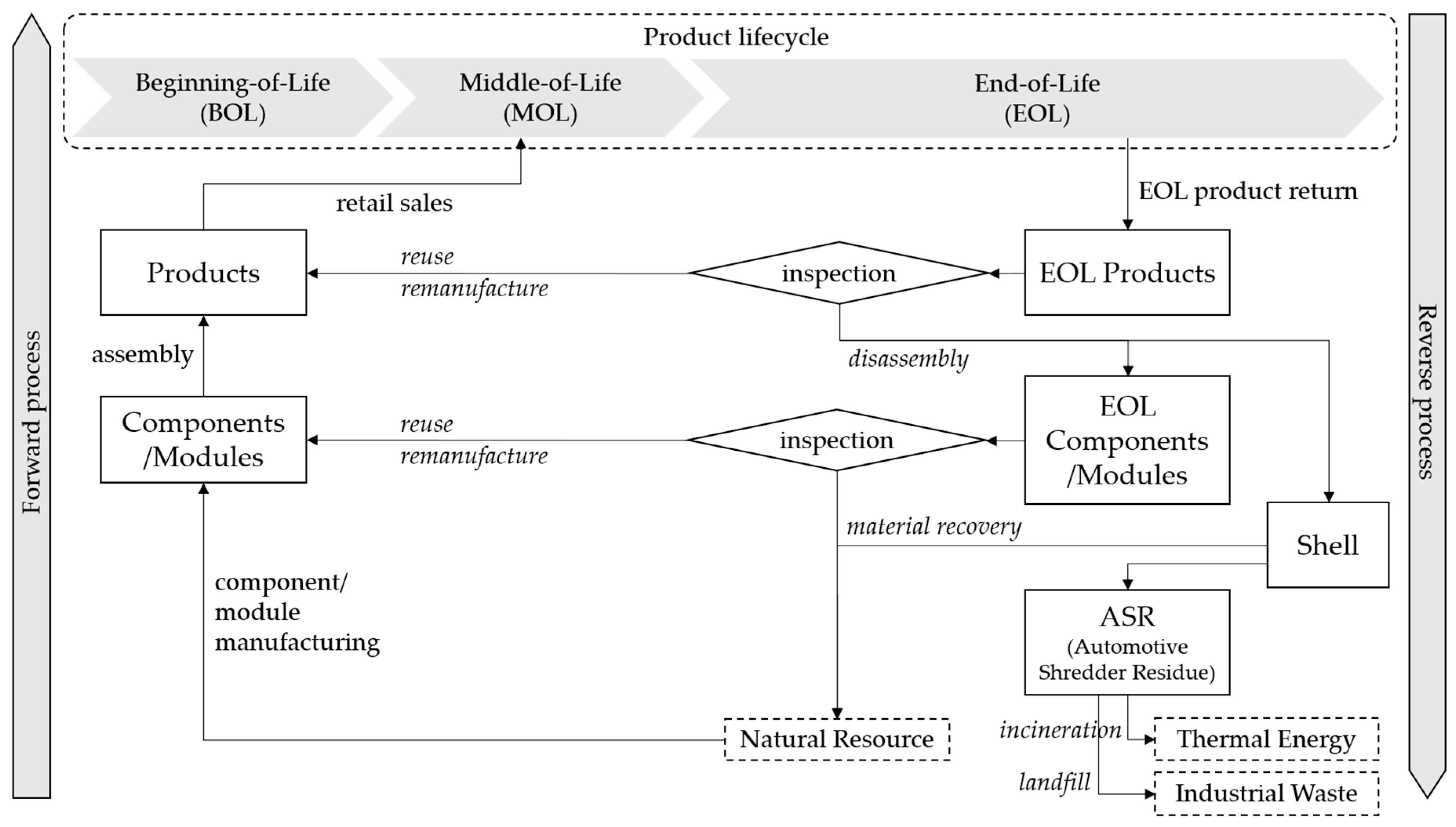
We explain how the CLSC process works using the automotive remanufacturing industry as an example. Automotive products are representative modular ones, which could be handled using the proposed system. In an automotive CLSC, operations such as remanufacturing, substitution, and repair happen frequently at a component/module level. Figure 1 represents the automotive CLSC. The CLSC of modular products has a similar flow, even if it is not for automotives.
For the reverse process, a returned product can be reused or remanufactured, but it rarely happens in a real-world situation. Most of the returned products are disassembled into lower level components and a shell. Components are reused or remanufactured if their condition turns out to be good enough for reuse or remanufacturing by inspection. Otherwise, it is recovered as raw material after shredding with the shell. Finally, automotive shredder residue (ASR) can be recovered as thermal energy by incineration. The current inspection system manually grades returned items based on expert opinions, without any lifecycle information. However, difficulty exists regarding the accurate estimation of residual values.
In Korea, the recycling rate of the automotive industry is about 90%, and is still increasing. The main driver of the increasing recycling rate is material recovery and ASR rather than remanufacturing, as depicted in Figure 2 [40]. Therefore, it is essential to increase the remanufacturing portion as much as possible to settle the efficient recycling system in consideration of the theoretical hierarchy of recycling options.
3. System Framework
As stated earlier, uncertainties regarding physical flow within the CLSC and quality within the product lifecycle negatively affect CLSCs. The proposed system aims to solve these problems, and ultimately operate the CLSC efficiently in terms of costs and resource circulation, by gathering real-time information generated during the product lifecycle. In addition, component-level tagging facilitates more detailed lifecycle information management, because lifecycle events and CLSC operations such as production, component substitution, disassembly, and recycling activities occur on a modular basis.
Figure 3 shows data generation and data flow, as well as expected effects by lifecycle phase. In the Product Design phase, information about product design—such as specifications of components and assembly structures among the components—is generated. This information related to the bill-of-materials (BOM) is stored in the BOM_DATA table. Instructions about disassembly and recovery works are stored in the design for remanufacturing (DFR) table. The beginning-of-life (BOL) phase starts with the production of components and products. Each item receives an EPC as a unique identity, with individual RFID tagging directly following its production. Likewise, upper-level components, modules, and products are also tagged with their EPCs. In addition, family relations, such as parent, child, and sibling, are created during assembly. For example, let module A be produced by the assembly of components B and C. In this case, B and C are the children of module A. Inversely, module A is a parent of B and C. Finally, B and C are siblings.
The PRODUCTION table contains this information, as well as production date, the worker who manufactures the item, and other production-related information. The proposed system gathers real-time information about maintenance, repair, and operations (MRO) events. Moreover, the RFID-based sensor integration scenario, which sends information gathered by auxiliary sensors through radio frequency (RF) communication, facilitates real-time monitoring of the product usage environment [41]. Product lifecycle visibility can be achieved by storing data that affects performance and residual value, as well as MRO events in the MRO_LOG table.
The proposed system facilitates various positive effects by using the stored data described above as a backend database. Counterfeit prevention and Real-time Monitoring and Maintenance (RMM) are provided for product service in the MOL phase. For products that have a revitalized secondhand market, frauds may exist—such as covering up accident history or using non-genuine components instead of genuine ones. The proposed system prevents these kinds of frauds by reference to MRO_LOG and by comparing family relations between RFID tags and the backend database.
In addition, RMM can be facilitated by real-time data capturing and analysis with auxiliary sensors. Sensors can be used to observe real-time data of key factors and send them to the analytics module by RF communication. This would enable us to detect an anomaly as an indication of potential failure in observations by the data-driven method in the analytics module. When the system detects the anomaly, a notification message is sent to the user in order to prevent critical damage. These kinds of sensing and control solutions have recently been diffusing into factories to manage equipment and production processes by obtaining various measurements. Our aim is to apply this solution to the product service area.
The EOL phase starts when a customer disposes of a product. After collection, the manufacturer decides how to recycle the returned product based on its condition. The proposed system enables data-driven recycling decisions based on gathered lifecycle information. Recycling decisions for each component are made individually and simultaneously, because the proposed system collects lifecycle information for each component by component-level tagging. Thereafter, recycling decisions indicate which component should be reused, remanufactured, disassembled, or shredded. Workers on the remanufacturing shop floor receive a job with predefined work instructions in the DFR table, according to the recycling decision made and stored in the WORK_LIST table; this supports workers and enables them to perform their jobs accurately.
The results of recycling activities are clearly recorded in the WORK_RESULT table. This not only facilitates obvious evidence for regulatory compliance, it also enables the efficient planning of manufacturing or remanufacturing by promoting resource awareness.
4. Data Architecture
Data architecture is designed for RFID tags and the backend database that supports the operation of the proposed system. Even though the capacity of RFID tags is increasing, there is obviously a limit. Therefore, it is important to discuss which data should be stored, and how data should be stored efficiently. The proposed system stores the required minimum information in RFID tags in a unified format, and the remainder in the backend database in a relational form.
In this paper, the focus is on bank01 (EPC), which provides a unique identity for each individual item, and bank11 (user memory), among four logically separated banks.
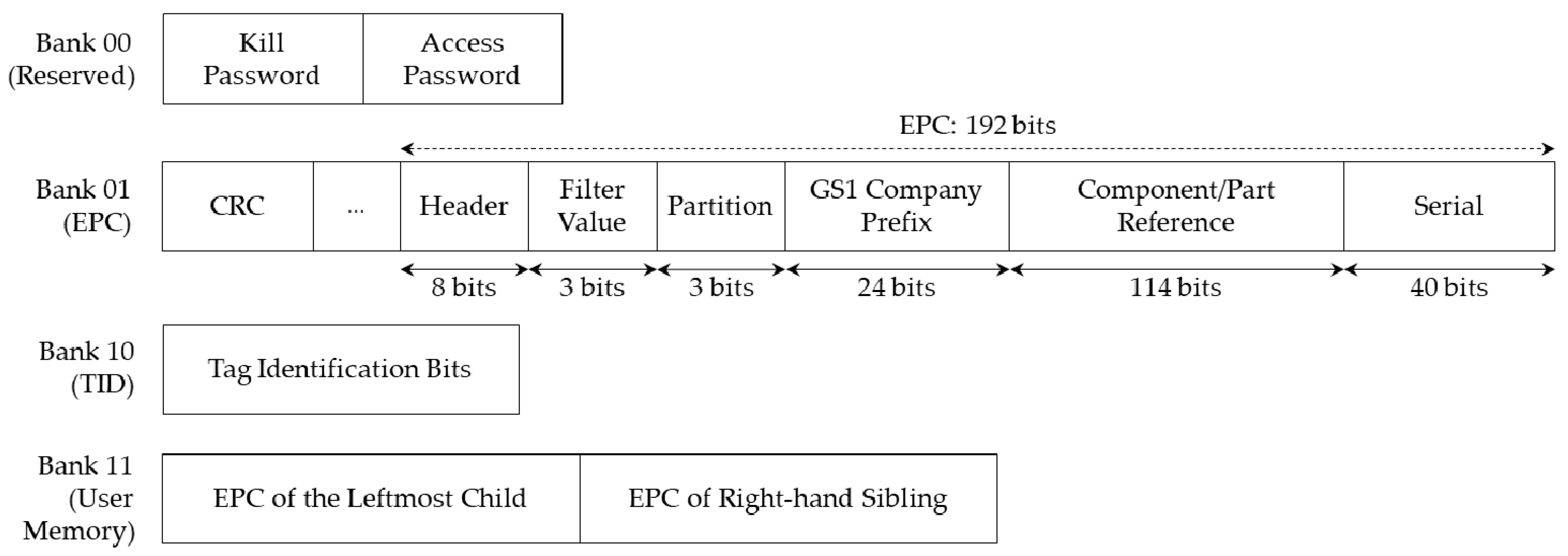
The Component/Part Identifier (CPI) encoding scheme is considered, which was originally designed for the unique identification of parts or components in technical industries (such as the automotive industry) to represent an EPC [42]. Its structure is similar to that of other standards, with a header, filter value, partition value, GS1 company prefix, component/part reference, and serial number. The CPI standard is divided into CPI-96, which has a fixed space of 96 bits, and CPI-var, which has a variable space ranging from 86 to 224 bits. The CPI-192 encoding scheme is proposed, which identifies more than 3.5*1053 items by assigning: 24 bits to represent the GS1 company prefix, 114 bits to represent the component/part reference, and 40 bits to represent the serial number. The proposed encoding scheme can minimize the waste of register capacity as one of the computational resources, because the processor runs in 32 or 64 bits, and 192 bits is the largest common multiple of 32 and 64 among the available space provided by CPI-var.
RFID tags represent a unique identity for the tagged object. In this context, the proposed system uses the user memory space to represent family relations about the tagged item as a part of the identity by using a partial ring structure with child and sibling pointers. A physical representation by using child and sibling pointers to represent a tree structure, as is the case for family relations, is used in the IBM information management system (IMS) hierarchical database management system. [43] A file in which the attribute has multiple values, such as a parent with multiple children, is known as a not-quite-flat file. The use of a variable-length record to store this kind of file would not be problematic. Although storing this kind of file using a variable-length record is feasible, it is difficult to use in real situation, because many software products only permit the use of fixed-length records, and the additional establishment of an encoding standard would not be beneficial. Well-known ways in which to store a not-quite-flat file with fixed-length records are as follows.
- Include space in the memory for the maximum possible number of records;
- Store in separate records and indicate the location by pointer;
- Include space for partial storage in the memory, store overflowed records separately, and indicate them by pointer.
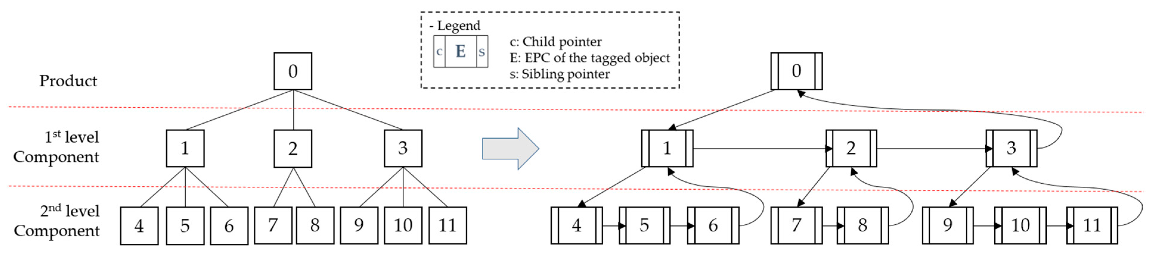
The first option is wasteful in terms of memory space, and it is also unstable, because the maximum possible number of records varies with circumstances. The other options are a burden on separate space. At this point, a partial ring structure in which every node has a uniform record length is proposed, with child and sibling pointers that represent family relations among components and indicate only the leftmost child and right-hand sibling. In the proposed structure nodes, the lowest level has a null value as a child pointer. However, a sibling pointer of the rightmost node among the nodes with the same parent indicates its parent in order to form a chain, as shown in Figure 4.
The overall memory map of the Gen2 tag that contains the CPI-192 standard in the EPC bank and family relationship in the user memory bank is shown in Figure 5.
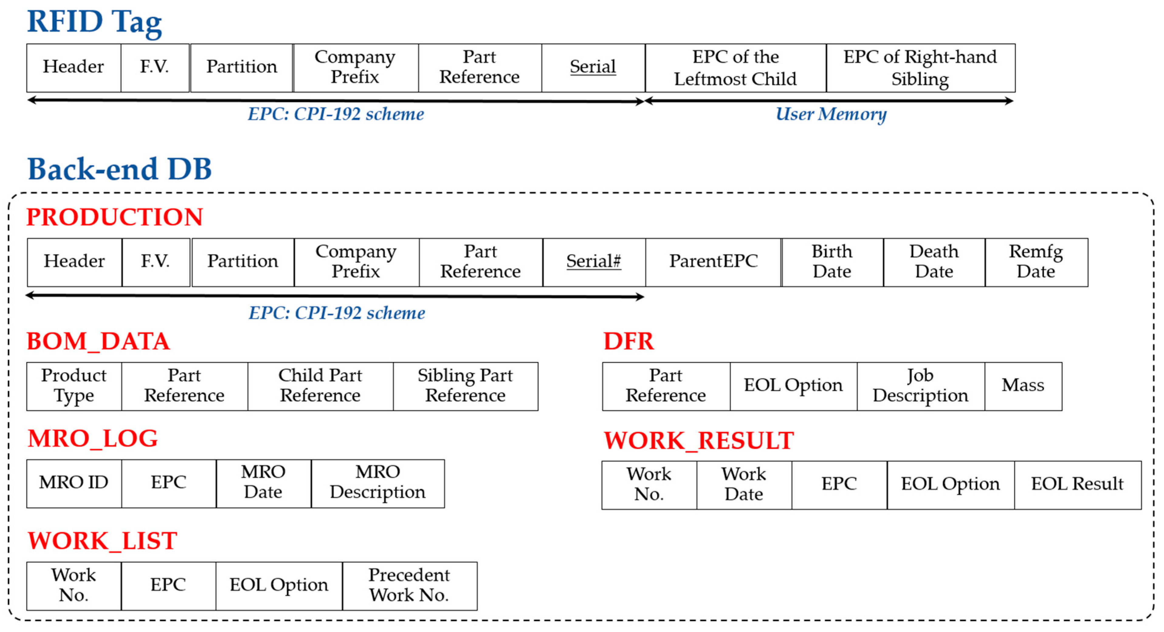
The overall schematic design of the database used in the proposed system is described in Figure 6. Each one of the RFID tags only contains its EPC and family relations, and the remaining information is stored in the backend database. The PRODUCTION table contains the EPC, the dates of birth, death, and remanufacturing, and the EPC of its parent’s tag. The BOMDATA and DFR tables contain the master data for products such as the product structure and work instructions for the remanufacturing shop floor by component and recycling option. The MRO_LOG table stores information about MRO events as a reference for the decision of a recycling option and review of the lifecycle history. Recycling options for each component, and the corresponding job sequence for recycling by the decision support system, are stored in the WORK_LIST table, whereas the WORK_RESULT table stores information about the actual result of recycling activities.
5. Application Scenario of the Proposed System
5.1. Counterfeit Prevention in the MOL Phase
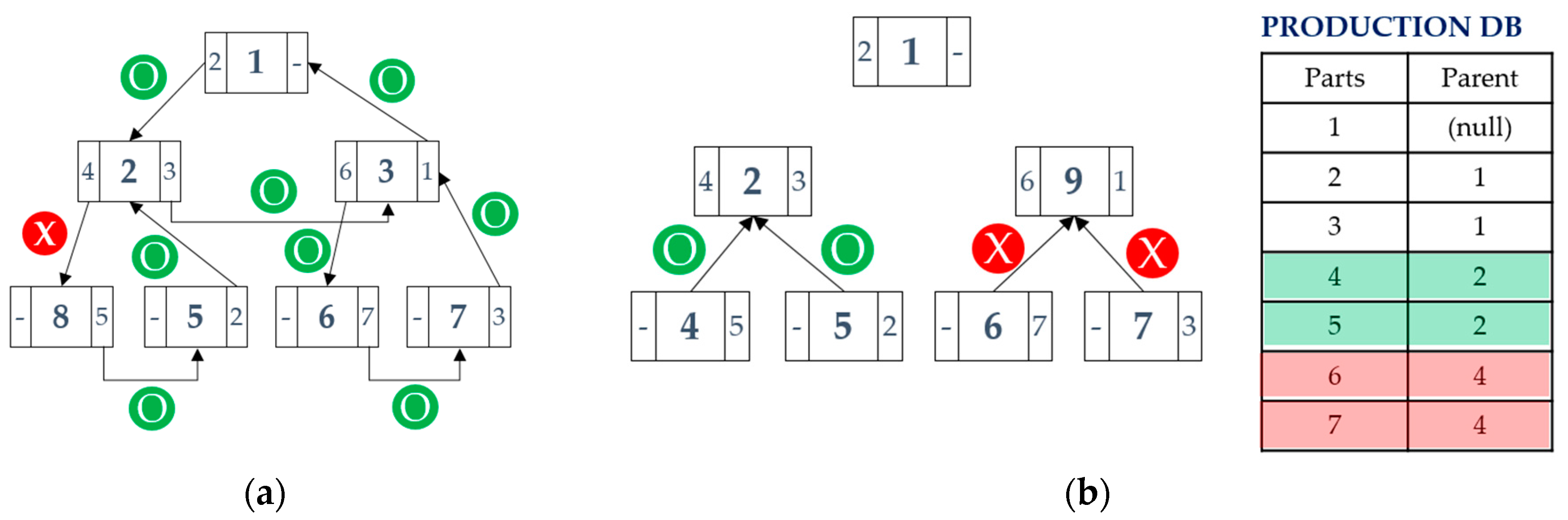
The proposed system detects any falsification of product structure by using two proposed methods—sweeping scan and cross-checking—with family relations stored in the backend database and the RFID tags. This procedure is illustrated in Figure 7.
The sweeping scan is employed in the top-down direction. At first, a product and an EPC of its leftmost child are identified in the first level. Then, an actual EPC of the leftmost child in the first level is compared with a previously identified EPC in the user memory of the product. If these values are different, the falsification of product structure could be detected. For the first level component, falsification is also detected by comparing actual EPCs and identified EPCs of its leftmost child and its right-hand sibling in its user memory. Thereafter, every linkage between components, as well as the product, can be compared by sweeping in a counterclockwise direction, as defined in the proposed partial ring structure. For example, Figure 7 illustrates that the sweeping scan detects a falsification on product 1, because component 2 should have component 4 as the leftmost child; however, the actual leftmost child identified is component 8. Therefore, it has the advantage that it works by using family relations stored in the user memory only, without external database access.
Cross-checking detects falsifications by comparing family relations stored in the PRODUCTION table in the backend database with identified EPCs, as illustrated on the right side of Figure 7.
5.2. Reverse Process Streamlining
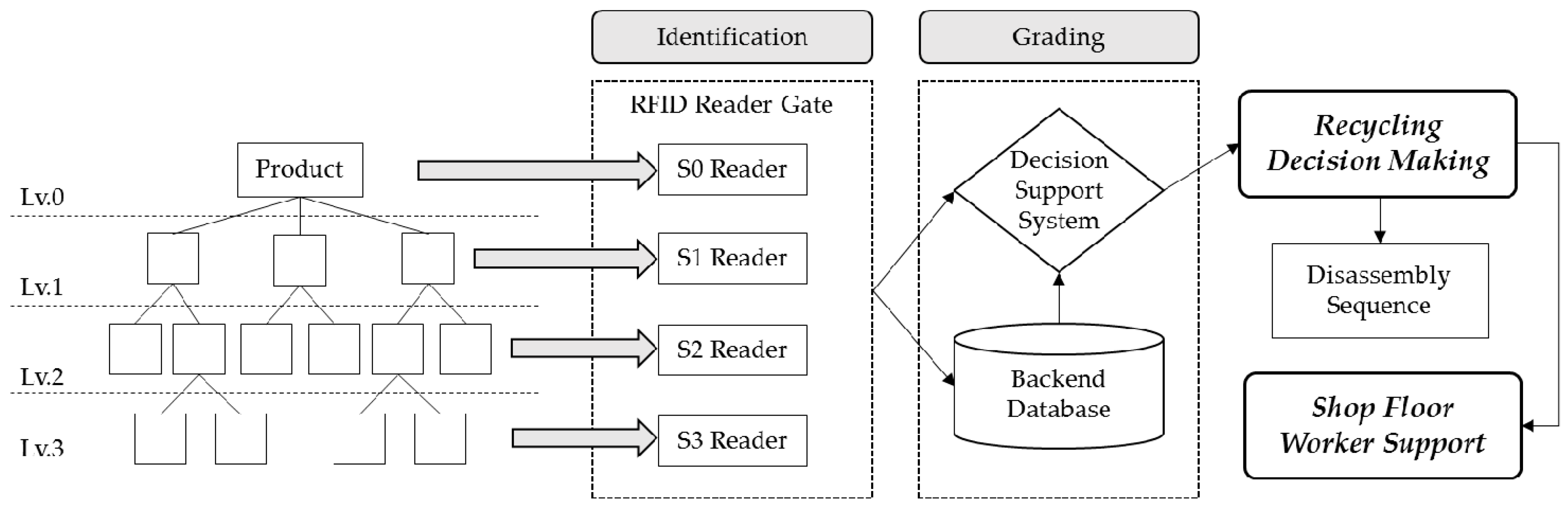
Products are recycled through the identification, grading, and remanufacturing processes after EOL returns, as described in Figure 8. The Gen2 RFID protocol provides four sessions, which allow readers to conduct independent inventories, with any tag only able to participate in one session. Each session has two inventory flags to represent its current status, and a state transition occurs when a tag is powered during a predefined persistence time. This enables us to read tags only in the particular state or session. Finally, the tags in the four types of sessions can be read without missing or without redundancy in high populations and dynamic environments. As described above, a product has multiple RFID tags that are individually attached to the components. S0 is assigned to the products, S1 to the first level components, S2 to the second level components, and S3 to the third level components. An RFID reader gate that consists of multiple readers for each session is able to read the returned product, as well as every component in the product, simultaneously. This is expected to be helpful for inventory management problems of various types of components.
After the RFID tag in the product is read, the system identifies every component in the product by using the sweeping scan described in the previous section. After the identification step, the decision support system selects a recycling option for each component based on the lifecycle information gathered during the whole product lifecycle. Subsequently, the corresponding job sequence for recycling is derived. Thereafter, the remanufacturing work is carried out according to the job sequence on the remanufacturing shop floor. When the worker receives the job, the MRO logs and the job instruction (which is written in the product design phase) are displayed on the monitor for worker support.
An illustrative example is presented to show how the proposed system differs from the conventional remanufacturing systems. Let there be four returned products, all with different qualities, as shown in Figure 9. Each box indicates a component, and a number in the box indicates an EPC of each item. Each digit in the three-digit EPC in the example indicates as follows: the first digit indicates the BOM level, the second digit indicates part types, and the last digit indicates the serial number. An appropriate recycling option of whether to reuse, remanufacture, disassemble, or recover in raw materials—as derived from the decision support system for each item—is given in parentheses.
A loop that consists of identification, grading, and testing exists for the recycling of modular products in a conventional system. At first, a product is disassembled to first-level components. For these components, the history log and expert opinion after identification will be used for grading, on which a decision for the appropriate recycling option is based. If the component is graded as reusable or remanufacturable, it goes to the shop floor. Otherwise, it should be disassembled to lower level components, and the same loop of identification, grading, and testing for the lower level components should be performed iteratively until the lowest level is reached. Let this scenario be SC1.
For another scenario, SC2, it is assumed that the system dismantles the product to the lowest level components unconditionally without any grading, and that a recycling decision is made only for them.
SC3, another scenario for the proposed system, identifies every component simultaneously and makes a decision for each component by using the decision support system. A component that is worth reusing or remanufacturing goes to the shop floor after testing; other components will be disassembled or recovered as raw materials.
In order to do recycling activities for product 113 in the example, the product is dismantled first, because reuse or remanufacturing at the product level rarely happens in the general situation. For scenario SC1, components 213 and 223 are identified and graded. Then, component 223 goes to the shop floor for reuse, and 213 is disassembled. Components 313 and 323, which are derived from 213, are also treated according to their recycling options after identification and grading. For scenario S2, a product and every component at the first level are disassembled. Then, second level components are recycled after identification and grading. SC3 is different to the other scenarios, because the identification and grading for every component in a product is executed at the first scan. Then, the disassembly of 113 and 213, and the material recovery of 323 are executed consecutively; the material recovery of component 323 is executed without any test. The other components, 223 and 313, are reused after testing, according to the recycling decision made during the first scan.
Job sequences were created according to the sequencing policies defined in the scenarios for the consecutive recycling of products 111, 112, 113, and 114. The number of components for disassembly, identification, grading, and testing is calculated for each scenario. The result, as listed in Table 2, shows that the proposed system is more efficient than the others, and that SC2 is better than SC1 in terms of the total number of jobs. However, when considering processing cost or time, SC2 is the worst scenario due to the disassembly cost, which is more than the costs of the other processes. Moreover, SC2 is worse than the others in terms of resource efficiency and opportunity cost, because remanufacturable or reusable upper-level components are disassembled rather than remanufactured or reused. In addition, it entails additional costs for unnecessary disassembly jobs.
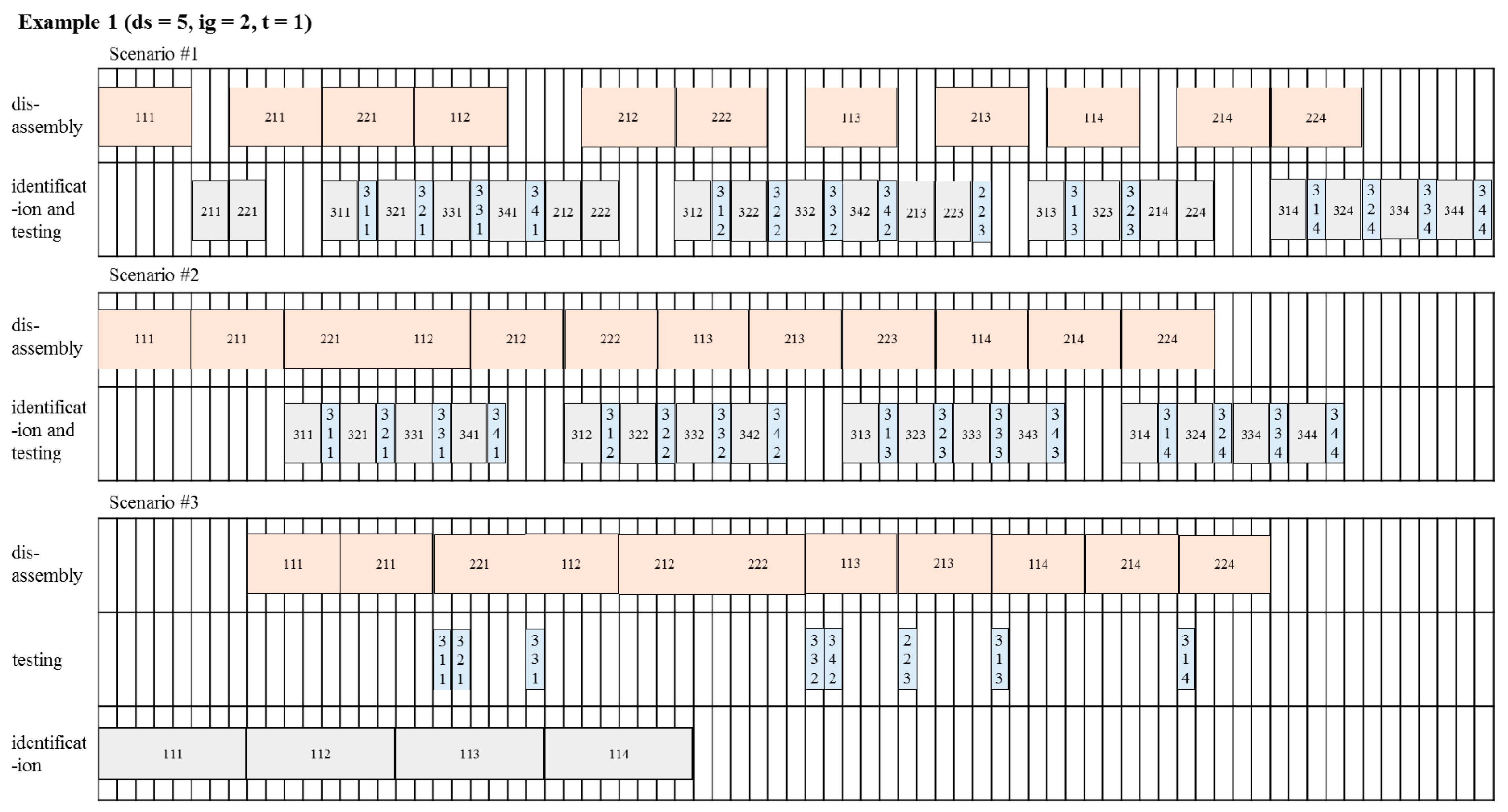
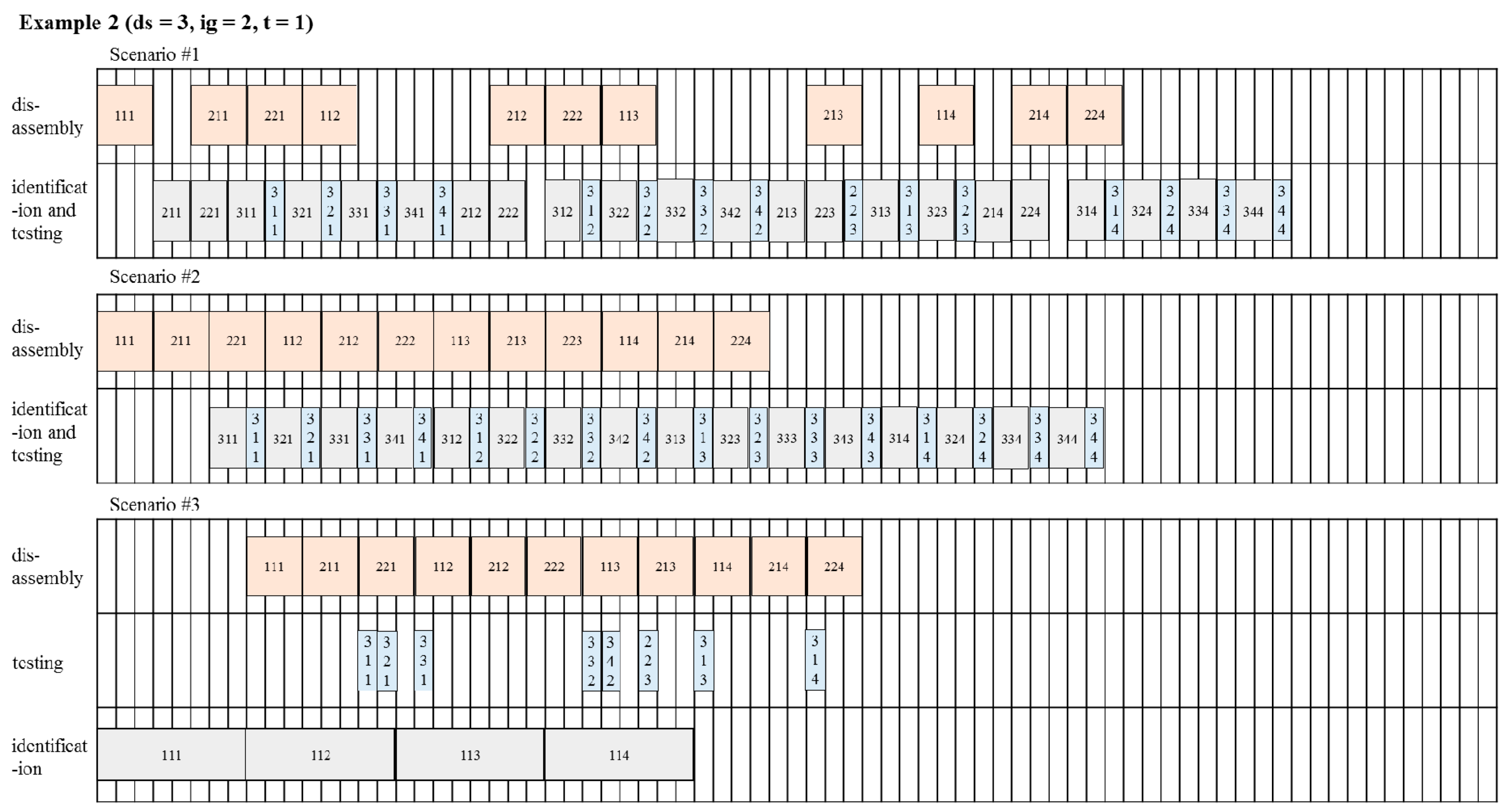
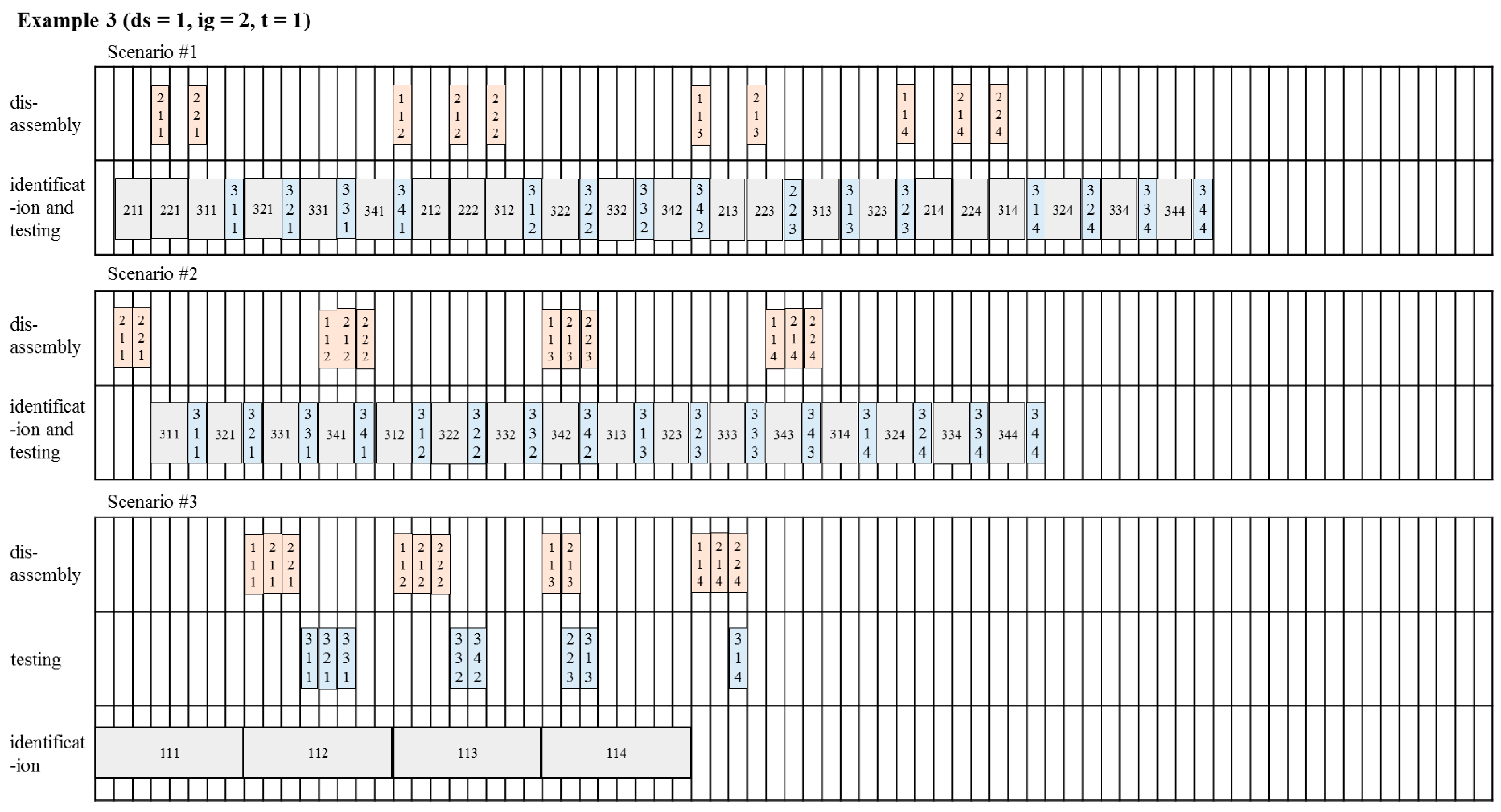
Job sequences are then presented for consideration of the costs, with various assumptions of disassembly processing time. Disassembly is known to be a labor intensive and expensive job. However, in the near future, many efforts to make disassembly easier, such as design for disassembly (DFD) may reduce disassembly time. In consideration of these circumstances, we assume different disassembly times for each example. The result is presented in Table 3, and sequence charts are presented in Figure 10, Figure 11 and Figure 12.
SC3 shows that it performs better than the conventional systems in terms of makespan, because the proposed system separates the identification and grading processes from the conventional identification–grading–testing process loop, which is executed in a single line. For the idle ratio, which is the average ratio of idle time to makespan, SC3 seems to be worse than the others. However, the greatest portion of idle time is from the testing line due to line separation, as shown in the process charts. This means that the system has surplus time to further tests for returned items.
6. Conclusions
A system framework for CLSC management was proposed for efficient operation in terms of economic as well as environmental values. The proposed system aims to solve the chronic problems related to lack of information by gathering real-time information within the product lifecycle and supply chain through the IoT environment using RFID and sensor networks. Since modular products consist of various types of components, we presented component-level tagging for consideration. RFID tags are attached to each component, as well as each product, to facilitate more detailed lifecycle information management, unlike conventional product-level tagging. The focus is specifically on the most recent UHF RFID protocol, Gen2, which provides new opportunities to improve the performance of the CLSC by using new features such as session and user memory.
Additionally, data structures were designed for the proposed system, including user memory in the RFID tags and the backend database. Traditionally, RFID has been used to represent a unique identity of a particular physical object. In this context, the family relations of objects—the leftmost child and the right-hand sibling—are stored in the user memory as a part of identities by using the partial ring structure, which is proposed for the efficient storage of tree-structured information. The proposed encoding scheme for RFID tags can be used in any industry, because it strictly follows current standards. The remainder of the information is stored in the backend database in a relational form after the anticipated information requirements have been established.
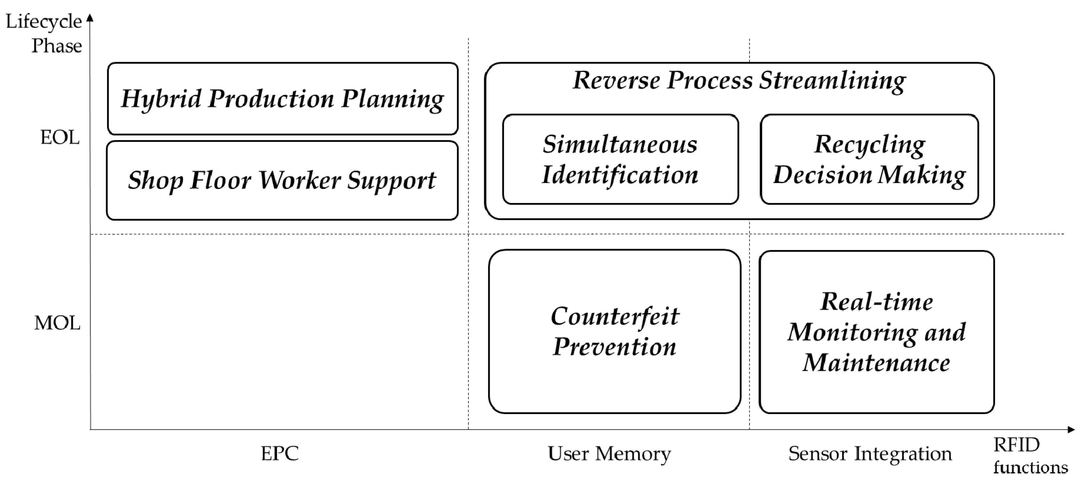
The potential positive impacts of the proposed system were examined during the MOL and EOL phases, as depicted in Figure 13. It also has potential benefits during the MOL phase in terms of product service. RMM, such as fault pre-detection and predictive maintenance, can be facilitated by detecting anomalies among real-time observations gathered by auxiliary sensors. Information from the sensors could also provide evidence of estimated residual values, and an appropriate recycling option in the EOL phase. The proposed system is able to prevent any counterfeits on product history and structure by storing MRO logs during the MOL phase. In addition, two methods are proposed—sweeping scan and cross-checking—to detect structural counterfeits. This is meaningful for the health of secondhand markets.
The proposed system also has the merit of reverse process streamlining in the EOL phase. For the conventional recycling process, there exists an unnecessary loop that consists of identification, testing, and grading. The proposed system uses component-level tagging to facilitate automated grading component by component, based on lifecycle information. Using family relation information in the user memory, the sweeping scan helps to identify every component simultaneously without any disassembly. Then, it eliminates the unnecessary loops, and minimizes the number of disassembly that is known to be expensive and time consuming. Positive effects were illustrated in terms of the number of recovery jobs and makespan by means of examples. Additionally, workers on the shop floor may have help from job instructions to do recovery work accurately.
In addition, every recycling activity and the corresponding results are digitally stored in the database. These can be utilized not only as clear evidence for environmental regulation compliance, but also as an enabler of resource awareness for hybrid planning of manufacturing or remanufacturing. Furthermore, the session, a kind of virtual class provided by the Gen2 protocol, helps to manage complex inventory with various types of components.
The proposed system is expected to be helpful for operating CLSC, not only for automotive products, but also for other modular products that consist of various types of components. However, comprehensive discussion with domain experts is required for application of the proposed system, since key factors that represent the product lifecycle and the information required to estimate residual value are all different. Although the economic feasibility of automated identification technology on ELV (end-of-life vehicle) management processes has been proved [44], cost-benefit analysis should precede system implementation.
Acknowledgments
This work was supported by ASRI (Automation and Systems Research Institute); National Research Foundation of Korea (NRF) grant funded by the Korea government (Ministry of Science, ICT & Future Planning) (No. 2015R1A2A2A03008086).
Author Contributions
Kim and Chang conceived and designed the system framework; Kim designed the data architecture and performed the application of the example scenarios; Kim, Chang and Park analyzed the application result and wrote the paper.
Conflicts of Interest
The authors declare no conflict of interest.
References
- Seliger, G.; Kim, H.J.; Kernbaum, S.; Zettl, M. Approaches to sustainable manufacturing. Int. J. Sustain. Manuf. 2008, 1, 58–77. [Google Scholar] [CrossRef]
- Ober, J.A. Mineral Commodity Summaries 2017; US Geological Survey: Reston, VA, USA, 2017.
- Global Resources Stock Check. BBC Future, 18 June 2012.
- Krikke, H.; Bloemhof-Ruwaard, J.M.; Van Wassenhove, L.N. Design of Closed Loop Supply Chains: A Production and Return Network for Refrigerators; Erasmus Research Institute of Management (ERIM): Rotterdam, The Netherlands, 2001. [Google Scholar]
- Lifset, R.; Atasu, A.; Tojo, N. Extended producer responsibility: National, international, and practical perspectives. J. Ind. Ecol. 2013, 17, 162–166. [Google Scholar] [CrossRef]
- United States International Trade Commission. Remanufactured Goods: An Overview of the Us and Global Industries, Markets, and Trade; United States International Trade Commision: Washington, DC, USA, 2012; Volume 4356, pp. 332–525.
- Kerr, W.; Ryan, C. Eco-efficiency gains from remanufacturing: A case study of photocopier remanufacturing at Fuji Xerox Australia. J. Clean. Prod. 2001, 9, 75–81. [Google Scholar] [CrossRef]
- Kwak, M. Green Profit Design for Lifecycle. Ph.D. Thesis, University of Illinois at Urbana-Champaign, Champaign, IL, USA, 2012. [Google Scholar]
- Clottey, T.; Benton, W. Core Acquisitions Planning in the Automotive Parts Remanufacturing Industry; Ohio State University: Columbus, OH, USA, 2010. [Google Scholar]
- Lee, D.; Park, J. RFID-based traceability in the supply chain. Ind. Manag. Data Syst. 2008, 108, 713–725. [Google Scholar] [CrossRef]
- Gubbi, J.; Buyya, R.; Marusic, S.; Palaniswami, M. Internet of things (IoT): A vision, architectural elements, and future directions. Future Gener. Comput. Syst. 2013, 29, 1645–1660. [Google Scholar] [CrossRef]
- Tonelli, F.; Evans, S.; Taticchi, P. Industrial sustainability: Challenges, perspectives, actions. Int. J. Bus. Innov. Res. 2013, 7, 143–163. [Google Scholar] [CrossRef]
- Sudarsan, R.; Fenves, S.J.; Sriram, R.D.; Wang, F. A product information modeling framework for product lifecycle management. CAD Comput. Aided Des. 2005, 37, 1399–1411. [Google Scholar] [CrossRef]
- Parlikad, A.K.; McFarlane, D. RFID-based product information in end-of-life decision making. Control Eng. Pract. 2007, 15, 1348–1363. [Google Scholar] [CrossRef]
- Thomas, V.; Neckel, W.; Wagner, S. Information technology and product lifecycle management. In Proceedings of the 1999 7th IEEE International Symposium on Electronics and the Environment (ISEE-1999), Danvers, MA, USA, 13 May 1999; pp. 54–57. [Google Scholar]
- Tibben-Lembke, R.S.; Rogers, D.S. Differences between forward and reverse logistics in a retail environment. Supply Chain Manag. 2002, 7, 271–282. [Google Scholar] [CrossRef]
- Chandrasegaran, S.K.; Ramani, K.; Sriram, R.D.; Horváth, I.; Bernard, A.; Harik, R.F.; Gao, W. The evolution, challenges, and future of knowledge representation in product design systems. CAD Comput. Aided Des. 2013, 45, 204–228. [Google Scholar] [CrossRef]
- Denno, P.; Thurman, T. Requirements on information technology for product lifecycle management. Int. J. Prod. Dev. 2005, 2, 109–122. [Google Scholar] [CrossRef]
- Kiritsis, D.; Bufardi, A.; Xirouchakis, P. Research issues on product lifecycle management and information tracking using smart embedded systems. Adv. Eng. Inf. 2003, 17, 189–202. [Google Scholar] [CrossRef]
- Kiritsis, D. Closed-loop PLM for intelligent products in the era of the internet of things. CAD Comput. Aided Des. 2011, 43, 479–501. [Google Scholar] [CrossRef]
- Yang, X.; Moore, P.R.; Wong, C.; Pu, J.; Chong, S.K. Product lifecycle information acquisition and management for consumer products. Ind. Manag. Data Syst. 2007, 107, 936–953. [Google Scholar] [CrossRef]
- Främling, K.; Harrison, M.; Brusey, J.; Petrow, J. Requirements on unique identifiers for managing product lifecycle information: Comparison of alternative approaches. Int. J. Comput. Integr. Manuf. 2007, 20, 715–726. [Google Scholar] [CrossRef]
- Jun, H.B.; Shin, J.H.; Kim, Y.S.; Kiritsis, D.; Xirouchakis, P. A framework for RFID applications in product lifecycle management. Int. J. Comput. Integr. Manuf. 2009, 22, 595–615. [Google Scholar] [CrossRef]
- Cao, H.; Folan, P.; Mascolo, J.; Browne, J. RFID in product lifecycle management: A case in the automotive industry. Int. J. Comput. Integr. Manuf. 2009, 22, 616–637. [Google Scholar] [CrossRef]
- Kubler, S.; Derigent, W.; Främling, K.; Thomas, A.; Rondeau, É. Enhanced product lifecycle information management using “communicating materials”. CAD Comput. Aided Des. 2015, 59, 192–200. [Google Scholar] [CrossRef]
- Scheidt, L.-G.; Zong, S. Approach to achieve reusability of electronic modules. In Proceedings of the 1994 IEEE International Symposium on Electronics & the Environment, San Francisco, CA, USA, 2–4 May 1994; pp. 331–336. [Google Scholar]
- Meyer, G.G.; Främling, K.; Holmström, J. Intelligent products: A survey. Comput. Ind. 2009, 60, 137–148. [Google Scholar] [CrossRef]
- Klausner, M.; Grimm, W.M.; Hendrickson, C.; Horvath, A. Sensor-based data recording of use conditions for product takeback. In Proceedings of the 1998 IEEE International Symposium on Electronics and the Environment (ISEE 1998), Oak Brook, IL, USA, 4–6 May 1998; pp. 138–143. [Google Scholar]
- Li, J.; Tao, F.; Cheng, Y.; Zhao, L. Big data in product lifecycle management. Int. J. Adv. Manuf. Technol. 2015, 81, 667–684. [Google Scholar] [CrossRef]
- Simon, M.; Bee, G.; Moore, P.; Pu, J.S.; Xie, C. Modelling of the life cycle of products with data acquisition features. Comput. Ind. 2001, 45, 111–122. [Google Scholar] [CrossRef]
- Ilgin, M.A.; Gupta, S.M. Performance improvement potential of sensor embedded products in environmental supply chains. Resour. Conserv. Recycl. 2011, 55, 580–592. [Google Scholar] [CrossRef]
- Lu, Z.; Cao, H.; Folan, P.; Potter, D.; Browne, J. RFID-based information management in the automotive plastic recycling industry. In Proceedings of the 3rd International ICSC Symposium on Information Technologies in Environmental Engineering (ITEE 2007), Oldenburg, Germany, 29–30 March 2007; Kluwer Academic Publishers: Oldenburg, Germany, 2007; pp. 397–408. [Google Scholar]
- Saar, S.; Stutz, M.; Thomas, V.M. Towards intelligent recycling: A proposal to link bar codes to recycling information. Resour. Conserv. Recycl. 2004, 41, 15–22. [Google Scholar] [CrossRef]
- Luttropp, C.; Johansson, J. Improved recycling with life cycle information tagged to the product. J. Clean. Prod. 2010, 18, 346–354. [Google Scholar] [CrossRef]
- Wan, H.D.; Gonnuru, V.K. Disassembly planning and sequencing for end-of-life products with RFID enriched information. Rob. Comput. Integr. Manuf. 2013, 29, 112–118. [Google Scholar] [CrossRef]
- Kara, S.; Mazhar, M.; Kaebernick, H.; Ahmed, A. Determining the reuse potential of components based on life cycle data. CIRP Ann. Manuf. Technol. 2005, 54, 1–4. [Google Scholar] [CrossRef]
- Ondemir, O.; Ilgin, M.A.; Gupta, S.M. Optimal end-of-life management in closed-loop supply chains using RFID and sensors. IEEE Trans. Ind. Inf. 2012, 8, 719–728. [Google Scholar] [CrossRef]
- EPCglobal. EPC Radio-Frequency Identity Protocols Generation-2 UHF RFID; Specification for RFID Air Interface Protocol for Communications at 860 MHz–960 MHz; GS1 EPCglobal Inc.: Brussels, Belgium, 2013. [Google Scholar]
- Martin, H.; Millan, E.S.; Peris-Lopez, P.; Tapiador, J.E. Efficient ASIC implementation and analysis of two EPC-C1G2 RFID authentication protocols. IEEE Sens. J. 2013, 13, 3537–3547. [Google Scholar] [CrossRef]
- Korea Auto Dismantlement Recycling Association. Available online: http://www.kadra.or.kr (accessed on 13 May 2017).
- Pátkai, B.; McFarlane, D. RFID-Based Sensor Integration in Aerospace; Auto-ID Labs, University of Cambridge: Cambridge, UK, 2006; p. 1. [Google Scholar]
- EPCglobal. EPC Tag Data Standard 1.10; GS1 EPCglobal Inc.: Brussels, Belgium, 2017. [Google Scholar]
- Date, C.J. An Introduction to Database Systems; Addison-Wesley: Reading, MA, USA, 1990; Volume 1. [Google Scholar]
- Nam, K.; Chang, T.-W.; Park, J. Economic analysis on the implementation of automatic identification technologies in the end-of-life vehicle management process. Korean J. Logist. 2010, 18, 67–87. [Google Scholar]
Figure 1.
Material flow in the automotive closed-loop supply chain (CLSC).

Figure 2.
Annual statistics of Korean automotive recycling.
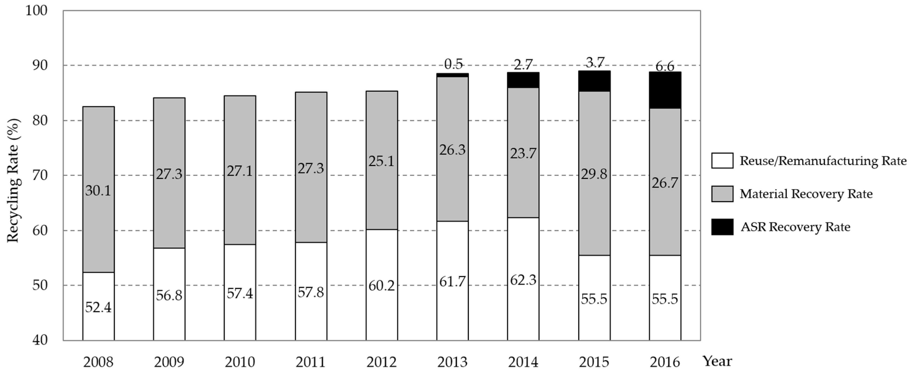
Figure 3.
Information system framework in this study.
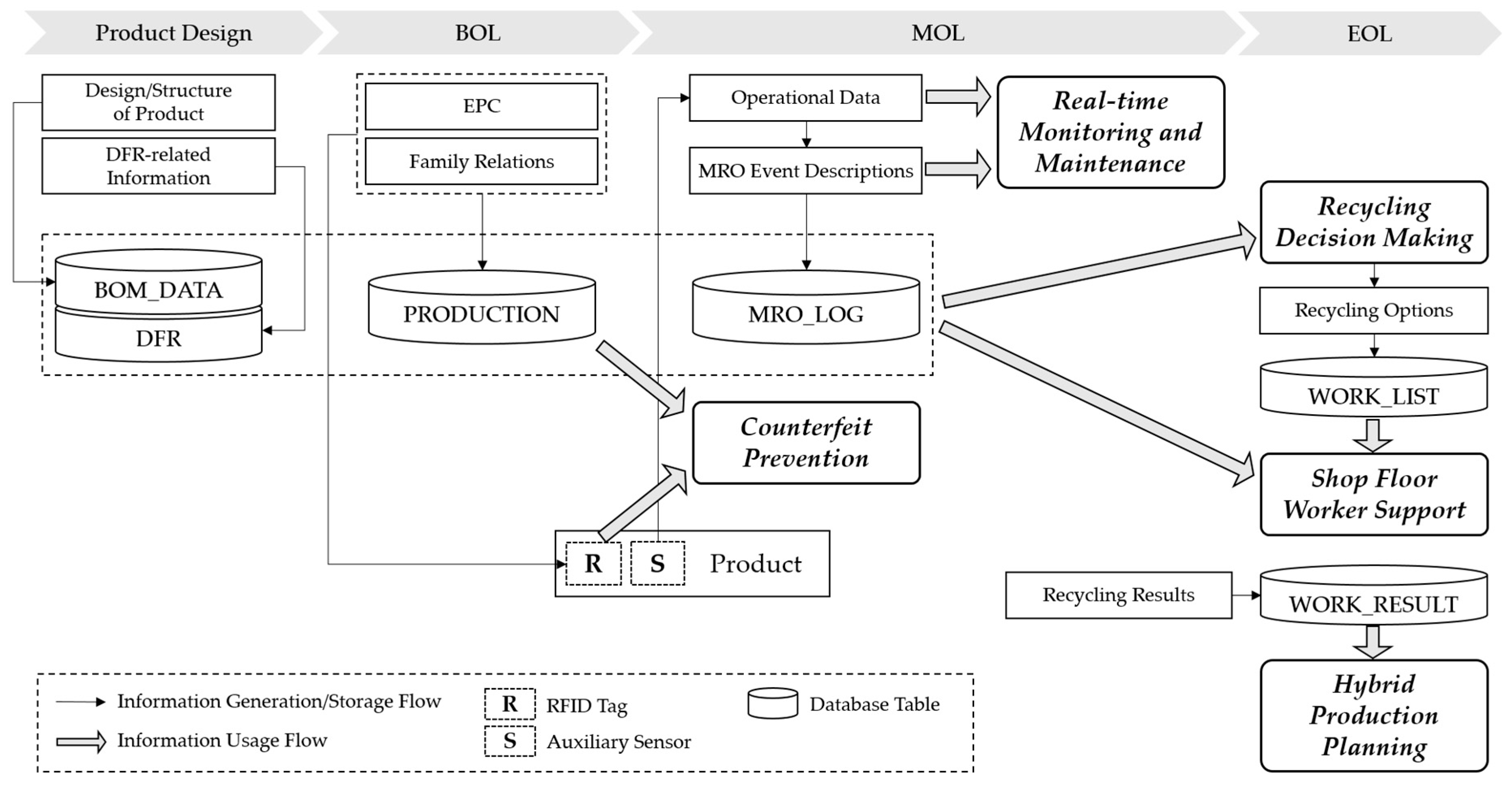
Figure 4.
Proposed partial ring structure.

Figure 5.
Overall Gen2 radio frequency identification (RFID) tag memory map.

Figure 6.
Schematic design of the overall database.

Figure 7.
Counterfeit prevention methods: (a) Sweeping scan; (b) Cross-checking.

Figure 8.
Improved reverse process.

Figure 9.
Example: returned products and qualities of items.
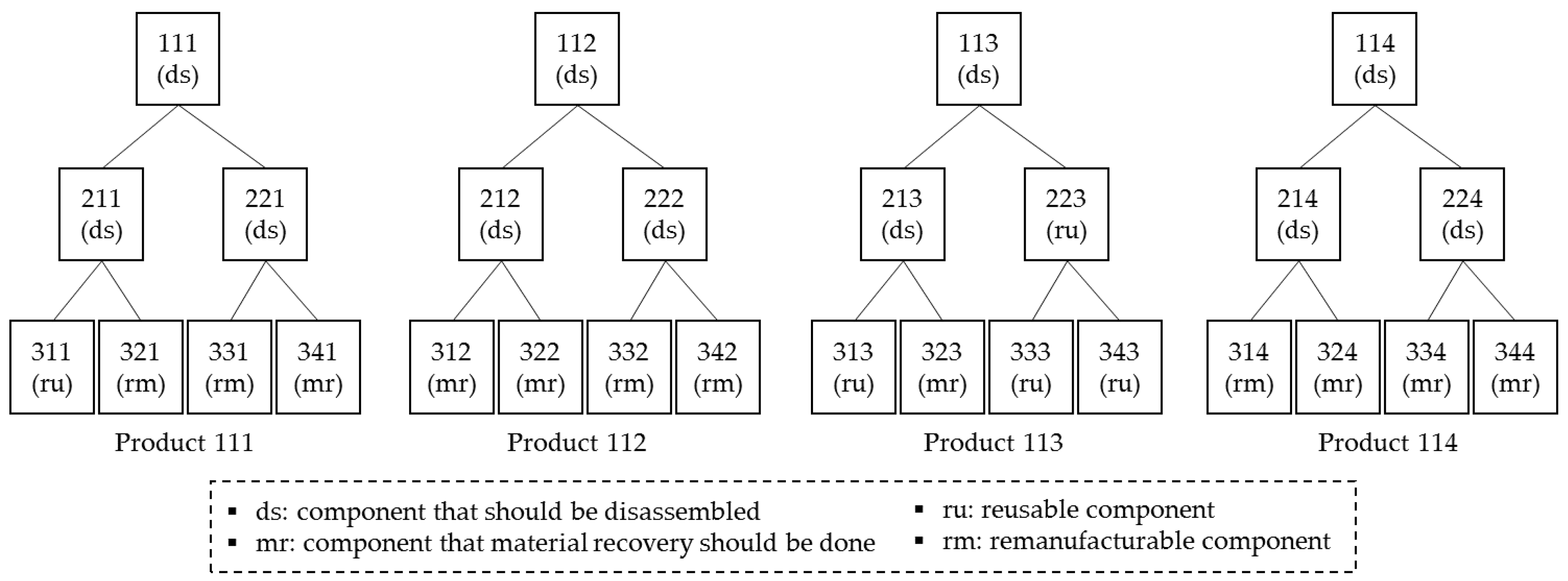
Figure 10.
Process sequence chart for Example 1.

Figure 11.
Process sequence chart for Example 2.

Figure 12.
Process sequence chart for Example 3.

Figure 13.
Potential impacts of the proposed system.

Table 1.
Theoretical Hierarchy of Recycling Options.
| Recycling Options | Descriptions [8] | Cost/Resource Circulation Efficiency |
|---|---|---|
| Reuse | An item is used for its original purpose without repair | Better |
| Remanufacture | An item maintains its identity and structure and is restored as a like-new product | |
| Material Recovery | An item is disassembled, shredded, and/or separated to recover raw materials | |
| Disposal | An item is sent to disposal sites either for landfill or incineration | Worse |
Table 2.
Number of jobs by type of process for each scenario.
| Scenario | SC1 | SC2 | SC3 | |||||||||
|---|---|---|---|---|---|---|---|---|---|---|---|---|
| Type of Process | ds 1 | ig 2 | t 3 | subtotal | ds | ig | t | subtotal | ds | ig | t | subtotal |
| Product 111 | 3 | 6 | 4 | 13 | 3 | 4 | 4 | 11 | 3 | 1 | 3 | 7 |
| Product 112 | 3 | 6 | 4 | 13 | 3 | 4 | 4 | 11 | 3 | 1 | 2 | 6 |
| Product 113 | 2 | 4 | 3 | 9 | 3 | 4 | 4 | 11 | 2 | 1 | 2 | 5 |
| Product 114 | 3 | 6 | 4 | 13 | 3 | 4 | 4 | 11 | 3 | 1 | 1 | 5 |
| Total | 11 | 22 | 15 | 48 | 12 | 16 | 16 | 44 | 11 | 4 | 8 | 23 |
1 Disassembly, 2 Identification and Grading, 3 Testing.
Table 3.
Performance measures by examples.
| Processing Time | Performance Measures | ||||||
|---|---|---|---|---|---|---|---|
| ds 1 | ig 2 | t 3 | Scenario | Makespan | Total Idle Time | Idle Ratio | |
| Example 1 | 5 | 2 | 1 | SC1 | 75 | 36 | 0.240 |
| 5 | 2 | 1 | SC2 | 67 | 26 | 0.194 | |
| 5 | 8 | 1 | SC3 | 63 | 94 | 0.497 | |
| Example 2 | 3 | 2 | 1 | SC1 | 64 | 36 | 0.281 |
| 3 | 2 | 1 | SC2 | 54 | 24 | 0.222 | |
| 3 | 8 | 1 | SC3 | 41 | 49 | 0.398 | |
| Example 3 | 1 | 2 | 1 | SC1 | 60 | 50 | 0.417 |
| 1 | 2 | 1 | SC2 | 51 | 42 | 0.412 | |
| 1 | 8 | 1 | SC3 | 35 | 54 | 0.514 | |
1 Disassembly, 2 Identification and Grading, 3 Testing.
© 2017 by the authors. Licensee MDPI, Basel, Switzerland. This article is an open access article distributed under the terms and conditions of the Creative Commons Attribution (CC BY) license (http://creativecommons.org/licenses/by/4.0/).
Share and Cite
MDPI and ACS Style
Kim, Y.-w.; Chang, T.-W.; Park, J. Gen2 RFID-Based System Framework for Resource Circulation in Closed-Loop Supply Chains. Sustainability 2017, 9, 1995. https://doi.org/10.3390/su9111995
AMA Style
Kim Y-w, Chang T-W, Park J. Gen2 RFID-Based System Framework for Resource Circulation in Closed-Loop Supply Chains. Sustainability. 2017; 9(11):1995. https://doi.org/10.3390/su9111995
Chicago/Turabian StyleKim, Young-woo, Tai-Woo Chang, and Jinwoo Park. 2017. "Gen2 RFID-Based System Framework for Resource Circulation in Closed-Loop Supply Chains" Sustainability 9, no. 11: 1995. https://doi.org/10.3390/su9111995
Note that from the first issue of 2016, this journal uses article numbers instead of page numbers. See further details here.