An Intelligent Luminance Control Method for Tunnel Lighting Based on Traffic Volume


1
School of Information Science and Technology, Dalian Maritime University, Dalian 116026, China
2
Department of Civil and Environmental Engineering, University of Houston, Houston, TX 77204, USA
3
High Grade Highway Construction Authority of Jilin Province, Jilin 130012, China
*
Author to whom correspondence should be addressed.
Sustainability 2017, 9(12), 2208; https://doi.org/10.3390/su9122208
Submission received: 1 November 2017
/
Revised: 26 November 2017
/
Accepted: 28 November 2017
/
Published: 30 November 2017
(This article belongs to the Section Energy Sustainability)
Abstract
:This paper presents an intelligent control method for tunnel lighting based on traffic volume. The monitoring data for a period of 12 days of the Chibai tunnel (located in the Jilin province of China) under different weather conditions was selected as the case study. The data used in the analysis included traffic volume, vehicle speed, the time of light-emitting diodes (LEDs) operating at their lowest luminance level, and the average time interval between two consecutive vehicles. The traffic flow analysis indicated that the tunnel has a relatively heavy traffic volume in the daytime (7:00 a.m. to 6:00 p.m.) and a relatively low traffic volume in the nighttime (12:00 a.m. to 6:00 a.m. and 7:00 p.m. to 12:00 a.m.). Thus, we propose a tunnel lighting control method that distinguishes day and night operational strategies. In the daytime, the luminance of tunnel zones depends on tunnel exterior luminance, traffic volume and vehicle speed regardless of vehicle presence. In the night, the “vehicle in, light brightens; vehicle out, light darkens” control method is adopted for the tunnel luminance, which depends on vehicle presence.
1. Introduction
Unlike an open road, a tunnel road is a relatively enclosed space where the lighting abruptly changes from bright to dark (“black hole”) at the entrance of the tunnel and from dark to bright light (“bright hole”) at the exit of the tunnel (see Figure 1). The above abrupt changes produce the “adaptation lagging phenomenon”, where drivers require an adaptation time to discern the targets and objects of the tunnel interior [1,2,3,4]. Thus, the lighting lamps should be installed in order to provide adequate luminance at the tunnel entrance and the threshold zone to allow time for eye adaptation. Currently, energy consumption of tunnel lighting is larger than half of tunnel total energy consumption [5,6]. Hence, research on tunnel lighting energy saving has received significant attention in the last few years [7,8,9,10,11,12,13].
In order to meet the requirements of traffic safety and energy saving of tunnel lighting, various methods and technologies are adopted to minimize energy consumption in tunnel lighting systems. In particular, many intelligent lighting control technologies were developed to take advantage of the latest developments of light-emitting diodes (LEDs), which provide benefits of providing high luminance, requiring less maintenance and starting up faster compared to commonly used light sources [14,15,16,17]. A commonly proposed intelligent control method consists of maintaining the LEDs in low power mode when there are no vehicles in the tunnel and adjusting the LEDs in accordance with the exterior environmental luminance when there are vehicles approaching the tunnel. According to Nagai et al. [18], the aforementioned method is limited to conditions when there are not frequent changes in the lighting operational modes or the traffic flow is relatively low (traffic volume of each day is less than 500 vehicles), which would not be suitable for relatively high-traffic volumes.
This paper describes an intelligent control method for tunnel lighting, which distinguishes day and night operational strategies. During the day, when the traffic volume is relatively heavy, the luminance of tunnel interior is determined by tunnel exterior environmental luminance, traffic volume and vehicle speed. The latter strategy avoids the frequent change of lighting operational modes, which would extend the lifetime of the lighting system. During the night, the traffic flow is relatively low, and the time interval between two consecutive vehicles is longer than daytime. For these conditions, a “vehicle in, light brightens; vehicle out, light darkens” energy-saving control strategy is adopted. The proposed intelligent control method aims to ensure traffic safety while maintaining the reliability of the lighting control system in the tunnel.
2. Tunnel Lighting Control Method Literature Review
The methods for tunnel lighting control have undergone three stages: manual control, sequential control and automatic control. Manual control, which is the earliest method employed in tunnel lighting, consists of turning lights on and off for different lighting circuits by the monitoring persons according to driving characteristics in an expressway tunnel during the day [19,20,21]. Sequential control divides the tunnel lighting operational modes into several categories according to the seasons and hours of the day [22]. Even though the two above methods are reliable and easy to implement in practice, the low degree of automation results in poor continuity and uniformity of luminance in tunnel interior [23]. Furthermore, when using the above two control methods, the lighting systems are generally not adjusted to the state of low energy consumption, even when there are no vehicles in tunnels. In addition, when using the above two control methods, the tunnel interior luminance is not adjusted according to the exterior environmental luminance, which leads to considerable waste of electrical energy [24].
Automatic control methods are designed to adjust automatically the tunnel interior luminance according to the exterior environmental luminance, traffic volume and vehicle speed, which makes it possible for more energy to be saved than the two aforementioned methods. Nagai [18] proposed an energy-saving system where the tunnel lighting is in standby mode when there are no vehicles in the tunnel. In this condition, the energy consumption can be as low as 12.5% of the maximum power. When the approach of a vehicle is detected, the tunnel interior luminance is turned up to 100% of the lighting condition. Carni [25] introduced an intelligent control method for tuning automatically the tunnel interior luminance based on input signals of external luminance, climatic condition and traffic volume. Yi [26] presented a control LED tunnel lighting system based on the external luminance of the tunnel, vehicle speed and traffic flow. In this approach, the tunnel lighting is adjusted following the illumination curve of CIE (Commission internationale de l’éclairage) standards [27], which makes the dark and bright adaptation process more natural, which in turn safeguards the driving in the tunnel. Zeng [28] designed a fuzzy control strategy with stepless dimming for tunnel lighting and energy conservation. In this strategy, the LEDs automatically adjust to their minimum illumination when there are no vehicles in the tunnel. Musa [29] developed an adaptive tunnel lighting system where tunnel LEDs’ luminance is divided into three levels according to integration of presence of vehicle and light intensity. In this system, in-tunnel lighting would be adjusted to the maximum luminance (level 3) when there are vehicles in the tunnel and the light intensity is above average. During the night when there are no vehicles in the tunnel, in-tunnel lighting would be adjusted to the minimum luminance (level 1). Otherwise, in-tunnel lighting would be adjusted to another luminance (level 2).
Until now, most research focused on methods and technologies for reducing energy consumption and related costs. One very common method for reducing energy consumption is to reduce the luminance level whenever there is no traffic flow in the tunnel. Although this method is proposed by many researchers, it has not been widely adopted in practice due to the frequent and fast switching of different control modes in relatively high-traffic tunnels.
3. Demand Luminance for Tunnel Interior
In order to ensure that the vehicular traffic traverses the tunnel in the most comfortable and safe way possible [30], the demand luminance of each zone in a tunnel is calculated based on tunnel exterior environmental luminance, driving speed and traffic flow. The adaptation curve of the tunnel luminance is shown in Figure 1. The CIE Publ. 88 [27] and the “Guidelines for Design of Lighting of Highway Tunnels (China, JTG-2014)” [31] standards divide the longitudinal section of the tunnel into five zones with different levels of demand luminance [32]: Access zone (Lacc); Threshold zone (Lth); Transition zone (Ltr); Interior zone (Lin), and; Exit zone (Lex).
The calculation of zone lengths and interior luminance varies depending on the standards adopted or developed by a country. It is worth mentioning that the standard in CIE Publ. 88 (2004) was used by most countries for adapting the zone lengths and interior luminance to their specific regulations and conditions.
The equations in Table 1 for luminance calculation are obtained by linear regression according to the data in JTG-2014 [33,34]. In Table 1, L20(S) is the real-time exterior environmental luminance (cd/m2), which is the average luminance in the 20° conical field of view defined at the stopping distance (SD) from the tunnel entrance ; v is the vehicle speed (km/h), and N is the traffic volume (veh/(h·ln).
4. Traffic Flow Data Analysis
4.1. Structure of Tunnel Lighting Control System
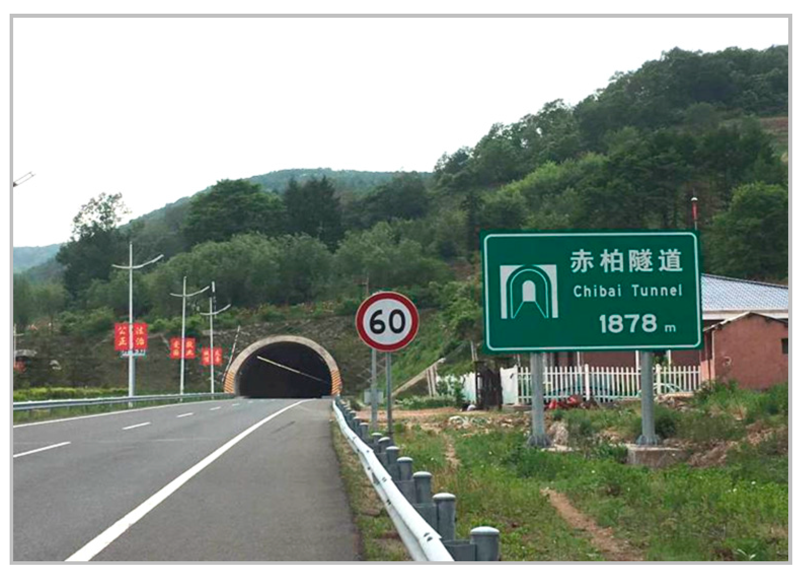
The proposed tunnel lighting energy-saving control method uses the Chibai Tunnel (Tonghua City), in the direction from Tonghua City to Shenyang City as a case study. The Chibai tunnel (Figure 2), which is located on TongShen highway in the Jilin Province of China, has a length of 1878 m, a width of 10.5 m, a height of 7.45 m, a speed limit of 60 km/h and a design vehicle speed of 80 km/h.
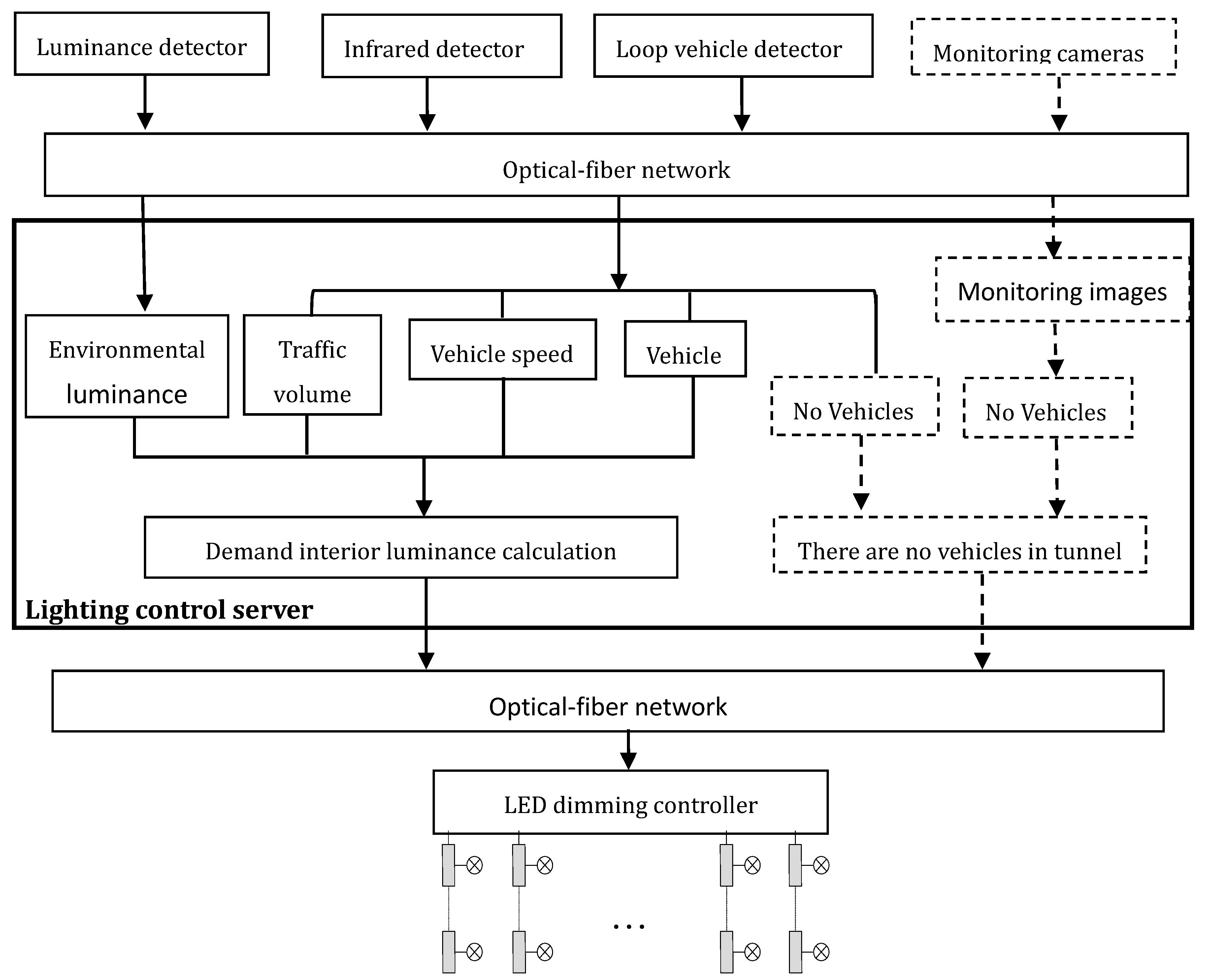
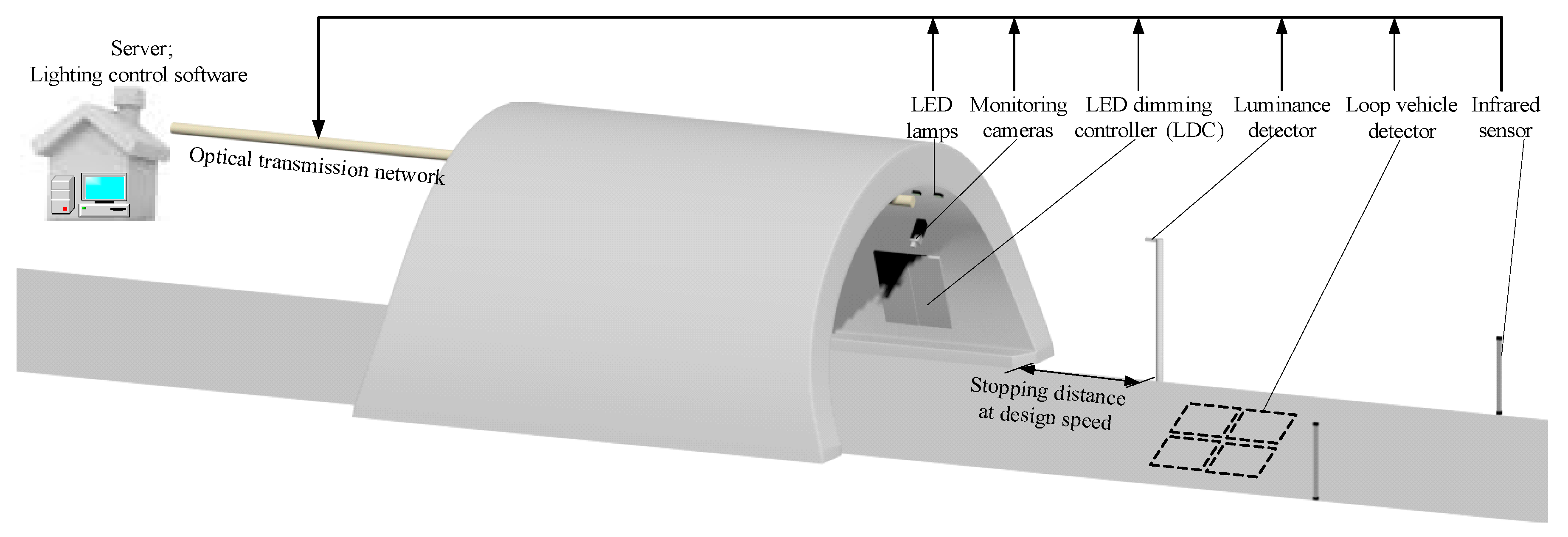
Figure 3 depicts the schematic of the hardware architecture of the Chibai tunnel lighting control system [35].
The hardware system mainly consists of vehicle detectors, luminance detector, LED dimming controllers, monitoring cameras, optical transmission network, tunnel lighting lamps, server and lighting control software in the tunnel operational monitoring center. The vehicle detectors [36] include the infrared detector and loop vehicle detector, and they are installed outside of the tunnel entrance to detect if vehicles are about to enter the tunnel, vehicle speed and traffic volume [37]. The luminance detector is placed about a stopping distance (which varies according to design vehicle speed) from the tunnel entrance. The monitoring cameras are placed 3.5 m above the right wall of the tunnel at intervals of 120 m to obtain an optimal view of the road and passing vehicles. The processing of image signals captured by the monitoring cameras is used to detect if there are vehicles in the tunnel [38,39,40]. The tunnel lighting software fully controls the tunnel lighting system by sending commands to LED dimming controllers through an optical transmission network and adjusting LED lamps’ power.
4.2. Traffic Statistical Analysis of the Chibai Tunnel
The monitoring data of 12 days that includes various conditions, such as weekends, weekdays, holidays, sunny days, cloudy days, and so forth, was selected for the present analysis.
Figure 4 shows the vehicle speed percentage distribution for each of the 12 days [41]. As can be observed in this figure, most vehicles speed range between 51 km/h and 90 km/h, and few of them exceed a speed of 110 km/h.
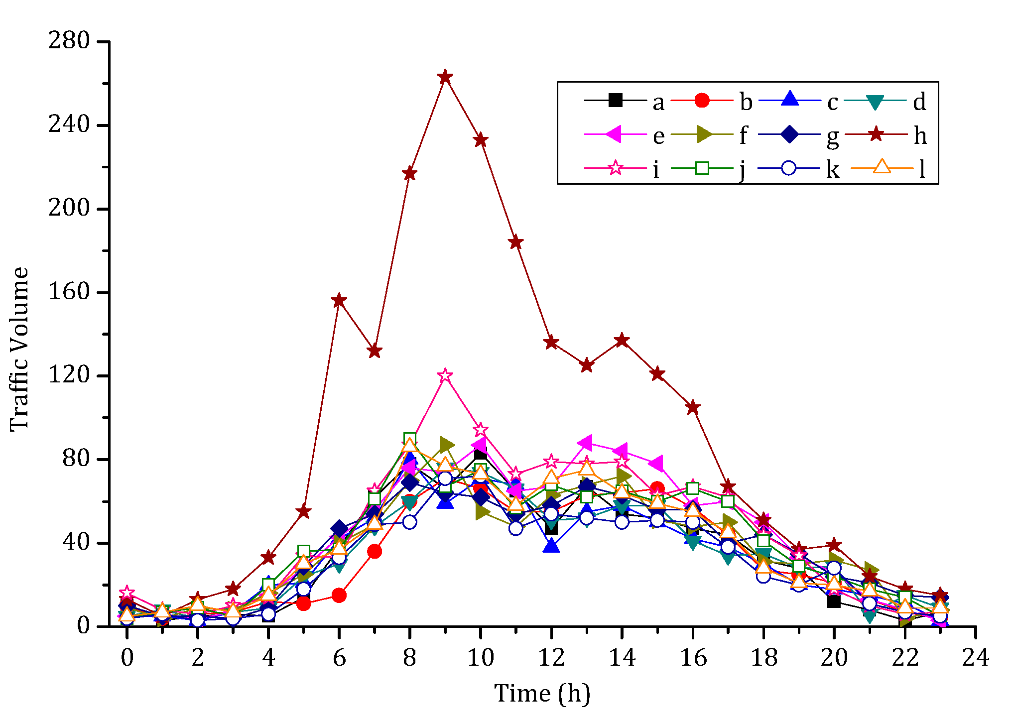
Figure 5 shows the traffic volume distribution for each of the 12 days. As shown in Figure 5, there are two peak periods, the first between 8:00 a.m. and 10:00 a.m., and the second between 1:00 p.m. and 3:00 p.m. Figure 5 also shows that the hourly traffic volume between 8:00 a.m. and 3:00 p.m. is higher than any other hours of the day. Furthermore, Figure 5 shows that the number of vehicles from 12:00 a.m. to 6:00 a.m. and from 8:00 p.m. to 12:00 a.m. is less than about 40 vehicles per hour, excluding the h line, which corresponds to the traffic volume of Labor Day in China. Moreover, the number of vehicles from 12:00 a.m. to 4:00 a.m. and from 10:00 p.m. to 12:00 a.m. is less than about 20 vehicles per six hours. Moreover, and not surprisingly, the traffic volume on Labor Day is substantially higher than the regular working days.
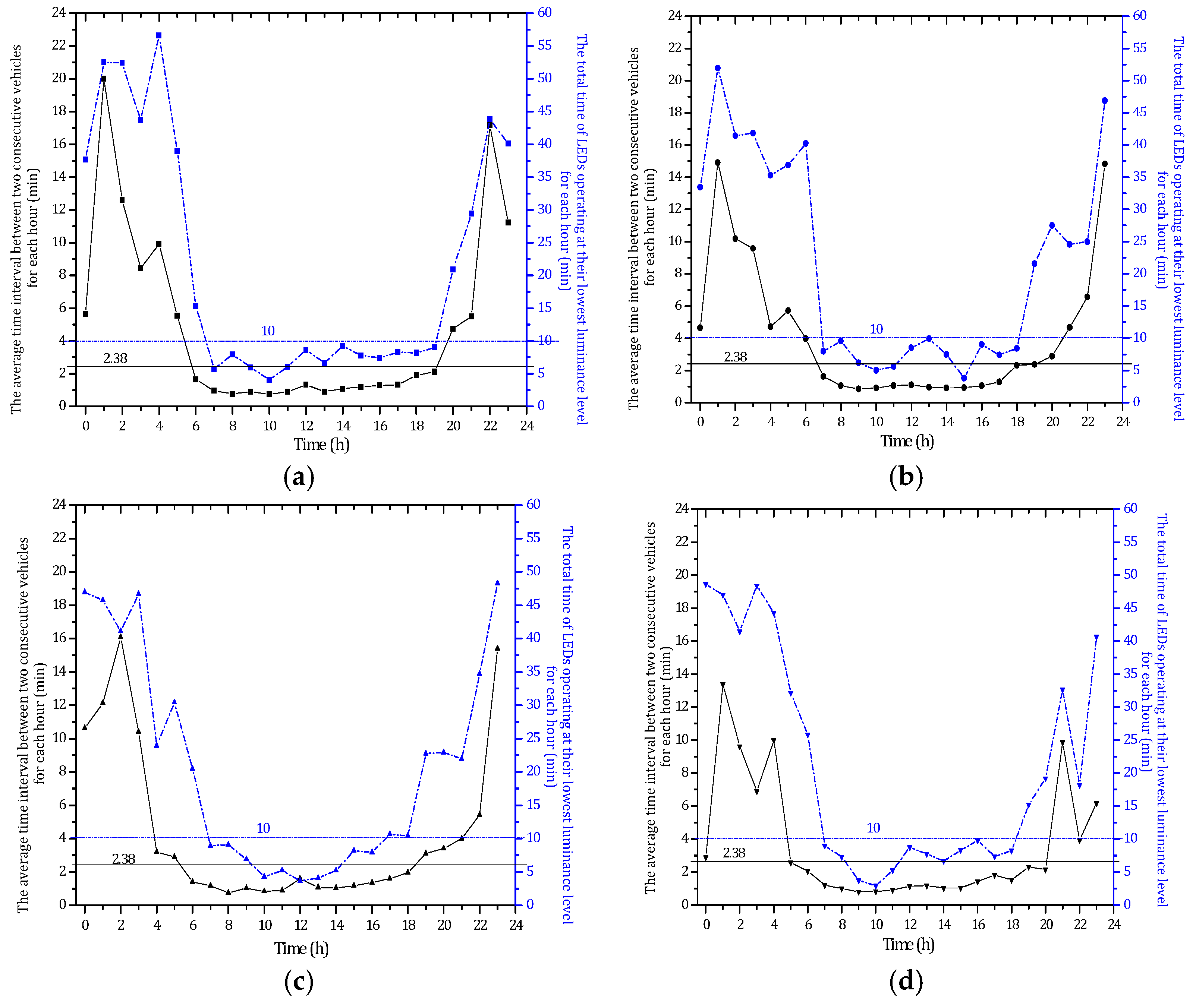
As mentioned above, when there are no vehicles in the tunnel, the tunnel lighting is set at the lowest luminance level. For this condition, the blue dashed lines in Figure 6a–l show the total time of LEDs operating at their lowest luminance level at each hour for day 1 to day 12, respectively. The black solid lines in these figures show the corresponding average time interval between two consecutive vehicles at each hour for each of the 12 days. According to the analysis of vehicle speed for the period of 12 days, the average vehicle speed is 59.9 km/h. And vehicle detectors are about 500 m outside the entrance to tunnel, so it will take 2.38 min ((1878 + 500 m)/(59.9 km/h)) for a vehicle to drive out of the tunnel from vehicle detected by detectors.
Thus, if the time interval between two consecutive vehicles is less than 2.38 min (black solid lines in Figure 6), there is no time for LEDs to operate at their lowest luminance level. In fact, as shown in Figure 6, when the average time interval between two consecutive vehicles is less than 2.38 min, LEDs operated at their lowest luminance level for a period of less than 10 min.
Table 2 presents the time period when the time interval between two consecutive vehicles (TP1) is less than 2.38 min for each of the 12 days. This table also shows the time period when LEDs are operating at their lowest luminance level (TP2) is less than 10 min.
As can be inferred from Table 2, a TP1 of less than 2.38 min corresponds to the time between 7:00 a.m. and 6:00 p.m. for each of the 12 days. Likewise, a TP2 less than 10 min corresponds to the time between 7:00 a.m. and 6:00 p.m. for each of the 12 days. A small value of TP1 in Figure 6 indicates a relatively large traffic volume as the time interval between two consecutive vehicles is small. On the contrary, a large value of TP1 indicates a relatively low traffic volume. Similarly, a large value of TP2 indicates a relatively low traffic volume as the LED system operated at their lowest luminance level for a relative long time due to the presence of no vehicles in the tunnel. On the contrary, a small value of TP2 indicates a relatively large traffic volume. In the proposed method, we consider as daytime the period from 7:00 a.m. to 6:00 p.m. and as nighttime the period from 12:00 a.m. to 6:00 a.m. and from 7:00 p.m. to 12:00 a.m. During the daytime (heavy traffic volume), the tunnel interior luminance is determined by tunnel exterior environmental luminance, traffic volume and vehicle speed. During the nighttime (low traffic volume), the tunnel interior luminance adopts the “vehicle in, light brightens; vehicle out, light darkens” energy-saving control strategy, which depends on the presence of vehicles in the tunnel.
In order to implement the proposed intelligent control method, it is important to distinguish between the periods for daytime and nighttime. The results in Section 4 are based on the data collected in March, April and May of 2017. The traffic volume in the summer or winter would be significantly different from these months. However, in any season, the traffic volume is relatively heavy in the daytime and low during nighttime.
5. Proposed Tunnel Lighting Control Method
This paper proposes an intelligent tunnel lighting control method that distinguishes operational strategies during daytime and nighttime. The operational strategy of the nighttime (from 12:00 a.m. to 6:00 a.m. and 7:00 p.m. to 12:00 a.m.) adopts a “vehicle in, light brightens; vehicle out, light darkens” control method, which depends on vehicle presence in the tunnel. During the daytime (from 7:00 a.m. to 6:00 p.m.), the tunnel interior luminance would be adjusted according to the tunnel exterior luminance, traffic volume and vehicle speed, whose luminance is calculated using the equations in Table 1.
Figure 7 presents the schematic of the operation of the tunnel lighting system. The infrared and loop vehicle detector together are used to detect the vehicle speed and the traffic volume. The luminance detector is used to collect the exterior environmental luminance in real time. Monitoring cameras installed in the tunnel are used to detect if there are vehicles inside the tunnel. During the day and night, the lighting control server calculates the demand luminance of each zone in the tunnel using the equations in Table 1 (see the ticker solid line rectangular box in Figure 7). Following this, the server sends commands to the LED dimming controller to adjust the tunnel LEDs’ luminance. This process is repeated continuously. During the night, when no vehicles are detected in the tunnel and no vehicles are about to enter the tunnel (dashed line box in Figure 7), the LED lamps are adjusted to their lowest luminance level, which is 10% of the maximum.
6. Conclusions
This study aimed to propose an intelligent control method for tunnel lighting based on traffic flow. The Chibai Tunnel, which is located in Tonghua City of Jilin Province of China, is used as the case study. The monitoring data of 12 days that includes various conditions, such as weekends, weekdays, holidays, sunny days, cloudy days, and so forth, was selected for the present analysis. The traffic flow analysis indicated that the tunnel has a relatively heavy traffic volume in the daytime (7:00 a.m. to 6:00 p.m.), and a relatively low traffic volume in the nighttime (12:00 a.m. to 6:00 a.m. and 7:00 p.m. to 12:00 a.m.). Thus, we propose a tunnel lighting control method that distinguishes day and night operational strategies. In the daytime, the luminance of tunnel zones depends on tunnel exterior luminance, traffic volume and vehicle speed regardless of vehicle presence. In the night, the “vehicle in, light brightens; vehicle out, light darkens” control method is adopted for the tunnel luminance, which depends on vehicle presence. The proposed method does not require image signal processing of the lighting control system during the daytime, which significantly simplifies the control system. The proposed method also reduces the average number of control switching in about 310 times per day, which would extend the system’s service life.
Acknowledgments
This paper was supported in part by the National Natural Science Foundation of China under Grant 61701069, the Fundamental Research Funds for the Central Universities of China under Grant 3132016351 and 3132017077, and the Project Sponsored by the Transportation Science & Technology of Jilin Province of China under Grant 2014-4-1-3.
Author Contributions
Li Qin analyzed the data, and wrote and revised the paper. Lili Dong and Wenhai Xu designed the whole system of tunnel control and supervised the whole process. Lidong Zhang collected the data from the experiment site and analyzed the data. Arturo S. Leon provided critical comments to the statistical analysis and gave suggestions/edits to improve the overall flow of the paper. All authors have read and approved the final manuscript.
Conflicts of Interest
The authors declare no conflict of interest.
References
- Roberts, A.C.; Christopoulos, G.I.; Car, J.; Soh, C.K.; Lu, M. Psycho-biological factors associated with underground spaces: What can the new era of cognitive neuroscience offer to their study? Tunn. Undergr. Space Technol. 2016, 55, 118–134. [Google Scholar] [CrossRef]
- Yeung, J.S.; Wong, Y.D. The effect of road tunnel environmental on car following behaviour. Accid. Anal. Prev. 2014, 70, 100–109. [Google Scholar] [CrossRef] [PubMed]
- Salata, F.; Golasi, I.; Poliziani, A.; Futia, A.; de Lieto Vollaro, E.; Coppi, M.; de Lieto Vollaro, A. Management optimization of the luminous flux regulation of a lighting system in road tunnels. A first approach to the exertion of predictive control systems. Sustainability 2016, 8, 1092. [Google Scholar] [CrossRef]
- Ferlazzo, F.; Piccardi, L.; Burattini, C.; Barbalace, M.; Giannini, A.M.; Bisegna, F. Effects of new light sources on task switching and mental rotation performance. J. Environ. Psychol. 2014, 39, 92–100. [Google Scholar] [CrossRef]
- Moretti, L.; Cantisani, G.; Di Mascio, P.; Caro, S. Technical and economic evaluation of lighting and pavement in Italian road tunnels. Tunn. Undergr. Space Technol. 2017, 65, 42–52. [Google Scholar] [CrossRef]
- He, S.; Liang, B.; Pan, G.; Wang, F.; Cui, L. Influence of dynamic highway tunnel lighting environment on driving safety based on eye movement parameters of the driver. Tunn. Undergr. Space Technol. 2017, 67, 52–60. [Google Scholar] [CrossRef]
- Peña-García, A.; Gil-Martín, L.M. Study of pergolas for energy savings in road tunnels. Comparison with tension structures. Tunn. Undergr. Space Technol. 2013, 35, 172–177. [Google Scholar] [CrossRef]
- Gil-Martín, L.M.; Peña-García, A.; Hernández-Montes, E.; Espín-Estrella, A. Tension structures: A way towards sustainable lighting in road tunnels. Tunn. Undergr. Space Technol. 2011, 26, 223–227. [Google Scholar] [CrossRef]
- Abdul Salam, A.O.; Mezher, K.A. Energy saving in tunnels lighting using shading structures. In Proceedings of the 2014 International Renewable and Sustainable Energy Conference (IRSEC), Ouarzazate, Morocco, 17–19 October 2014; pp. 519–524. [Google Scholar]
- Drakou, D.; Burattini, C.; Bisegna, F.; Gugliermetti, F. Study of a daylight “filter” zone in tunnels. In Proceedings of the IEEE International Conference on Environment and Electrical Engineering, Rome, Italy, 10–13 June 2015. [Google Scholar]
- Peña-García, A.; López, J.C.; Grindlay, A.L. Decrease of energy demands of lighting installations in road tunnels based in the forestation of portal surroundings with climbing plants. Tunn. Undergr. Space Technol. 2015, 46, 111–115. [Google Scholar] [CrossRef]
- Qin, X.; Zhang, X.; Qi, S.; Han, H. Design of solar optical fiber lighting system for enhanced lighting in highway tunnel threshold zone: A case study of Huashuyan Tunne in China. Int. J. Photoenergy 2015, 2015, 1–10. [Google Scholar] [CrossRef]
- Lu, Y.X.; Liu, G.G.; Wang, X.; Zhang, Q. A highway tunnel lighting method based on solar energy. Tunnel Constr. 2015, 35, 674–678. [Google Scholar]
- He, Y.; Lang, Z.; Wu, A.; Li, C. Research on intelligent control of tunnel lighting system based on LED. In Proceedings of the 2010 International Conference on Optoleectronics and Image Processing, Haikou, China, 11–12 November 2010; pp. 247–250. [Google Scholar]
- Mao, B.; Niu, P.; Huang, C. The design of the drive control chip for the solar LED lighting system. Modern Appl. Sci. 2008, 2, 75–80. [Google Scholar] [CrossRef]
- Elejoste, P.; Angulo, I.; Perallos, A.; Chertudi, A.; Zuazola, I.J.G.; Moreno, A.; Azpilicueta, L.; Astrain, J.J.; Falcone, F.; Villadangos, J. An easy to deploy street light control system based on wireless communication and LED technology. Sensors 2013, 13, 6492–6523. [Google Scholar] [CrossRef] [PubMed]
- Leccese, F. Remote-Control System of High Efficiency and Intelligent Street Lighting Using a ZigBee Network of Devices and Sensors. IEEE Trans. Power Deliv. 2013, 28, 21–28. [Google Scholar] [CrossRef]
- Nagai, S.; Ishida, S.; Shinji, M.; Nakagawa, K. Energy-saving Lighting System for Road Tunnel. In Proceedings of the Underground Space Use: Analysis of the Past and Lessons for the Future, Istanbul, Turkey, 7–12 May 2005; pp. 625–631. [Google Scholar]
- Li, L. Research on highway tunnel lighting control strategies. Sci. Technol. Assoc. Forum 2008, 2, 46–47. [Google Scholar]
- Duan, W. An intelligent highway tunnel lighting control. J. Changchun Univ. Technol. 2015, 36, 596–600. [Google Scholar]
- Huang, Y.G.; Yan-Ming, N.I.; Lun-Hui, X.U. Tunnel Illuminance Unlimited Dimming Method Based on Fuzzy Control. J. Guangxi Normal Univ. 2011, 29, 10–14. [Google Scholar]
- Ożadowicz, A.; Grela, J. Energy saving in the street lighting control system—A new approach based on the EN-15232 standard. Energy Effic. 2017, 10, 563–576. [Google Scholar] [CrossRef]
- Bellido-Outeiriño, F.J.; Quiles-Latorre, F.J.; Moreno-Moreno, C.D.; Flores-Arias, J.M.; Moreno-García, I.; Ortiz-López, M. Streetlight control system based on wireless communication over DALI protocol. Sensors 2016, 16, 597. [Google Scholar] [CrossRef] [PubMed]
- Fan, S.; Yang, C.; Wang, Z. Automatic Control System for Highway Tunnel Lighting. In Computer and Computing Technologies in Agriculture IV, Proceedings of the 4th IFIP TC 12 Conference, CCTA 2010, Nanchang, China, 22–25 October 2010; Advances in Information and Communication Technology; Springer: Boston, MA, USA, 2010; Volume 347, pp. 116–123. [Google Scholar]
- Carni, D.L.; Grimaldi, D.; Lamonaca, F.; Martirano, L. A smart control to operate the lighting system in the road tunnels. In Proceedings of the IEEE International Conference on Intelligent Data Acquisition and Advanced Computing Systems, Berlin, Germany, 12–14 September 2013; pp. 786–790. [Google Scholar]
- Yi, H.; Li, C.; Wu, A.; Feng, S. LED lighting control system in tunnel based on intelligent illumination curve. In Proceedings of the International Conference on Intelligent Computation Technology & Automation, Huangshan, China, 25–29 July 2012; pp. 698–701. [Google Scholar]
- Commission Internationale de l’Éclairage, CIE. Guide for the Lighting of Road Tunnels an Underpasses; CIE Publication: Vienna, Austria, 2004; Volume 88. [Google Scholar]
- Zeng, H.; Qiu, J.; Shen, X.; Dai, G. Fuzzy Control of LED Tunnel Lighting and Energy Conservation. Tsinghua Sci. Technol. 2011, 16, 576–582. [Google Scholar] [CrossRef]
- Musa, M.S.; Nallagownden, P.; Chiu, K.W.; Sarwar, M.B. Design and development of intelligent adaptive tunnel lighting system. In Proceedings of the IEEE Conference on Energy Conversion, Johor Bahru, Malaysia, 19–20 October 2015; pp. 289–292. [Google Scholar]
- Salata, F.; Golasi, I.; Bovenzi, S.; Vollaro, E.D.L.; Pagliaro, F.; Cellucci, L.; Coppi, M.; Gugliermetti, F.; Vollaro, A.D.L. Energy Optimization of Road Tunnel Lighting Systems. Sustainability 2015, 7, 9664–9680. [Google Scholar] [CrossRef]
- China Communications Press. Guidelines for Design of Lighting of Highway Tunnels; China Communications Press: Beijing, China, 2014; Available online: https://wenku.baidu.com/view/9d69f263bb68a98271fefafa.html (accessed on 26 November 2017).
- Moretti, L.; Cantisani, G.; Di Mascio, P. Management of road tunnels: Construction, maintenance and lighting costs. Tunn. Undergr. Space Technol 2016, 51, 84–89. [Google Scholar] [CrossRef]
- Fan, S.; Li, W. Auto-control System for Highway Tunnel Lighting. J. East China Jiaotong Univ. 2011, 28, 9–13. [Google Scholar]
- Qin, L.; Dong, L.; Xu, W.; Zhang, L.; Yan, Q.; Chen, X. A “vehicle in, light brightens; vehicle out, light darkens” energy-saving control system of highway tunnel lighting. Tunn. Undergr. Space Technol. 2017, 66, 147–156. [Google Scholar] [CrossRef]
- Daely, P.T.; Reda, H.T.; Satrya, G.B.; Kim, J.W.; Shin, S.Y. Design of smart LED streetlight system for smart city with web-based management system. IEEE Sens. J. 2017, 17, 6100–6110. [Google Scholar] [CrossRef]
- Todorović, B.M.; Samardžija, D. Road lighting energy-saving system based on wireless sensor network. Energy Effic. 2017, 10, 239–247. [Google Scholar] [CrossRef]
- Masek, P.; Masek, J.; Frantik, P.; Fujdiak, R.; Ometov, A.; Hosek, J.; Andreev, S.; Mlynek, P.; Misurec, J. A harmonized perspective on transportation management in smart cities: The novel IoT-driven environment for road traffic modeling. Sensors 2016, 16, 1872. [Google Scholar] [CrossRef] [PubMed]
- Castañeda, J.N.; Jelaca, V.; Frías, A.; Pižurica, A.; Philips, W.; Cabrera, R.R.; Tuytelaars, T. Non-Overlapping Multi-camera Detection and Tracking of Vehicles in Tunnel Surveillance. In Proceedings of the International Conference on Digital Image Computing: Techniques and Applications, Noosa, Australia, 6–8 December 2011; pp. 591–596. [Google Scholar]
- Rios-Cabrera, R.; Tuytelaars, T.; Gool, L.V. Efficient multi-camera vehicle detection, tracking, and identification in a tunnel surveillance application. Comput. Vis. Image Underst. 2012, 116, 742–753. [Google Scholar] [CrossRef]
- Marino, F.; Leccese, F.; Pizzuti, S. Adaptive Street Lighting Predictive Control. Energy Procedia 2017, 111, 790–799. [Google Scholar] [CrossRef]
- Wei, Z.; Lu, Q.; Shang, Y. Analysis of Traffic Flow Characteristics under Large Volume in Highway Tunnel Group Region. In Proceedings of the International Conference on Remote Sensing, Environment and Transportation Engineering, Nanjing, China, 1–3 June 2012; pp. 1–5. [Google Scholar]
Figure 1.
Tunnel lighting system subsection diagram and demand luminance curve.
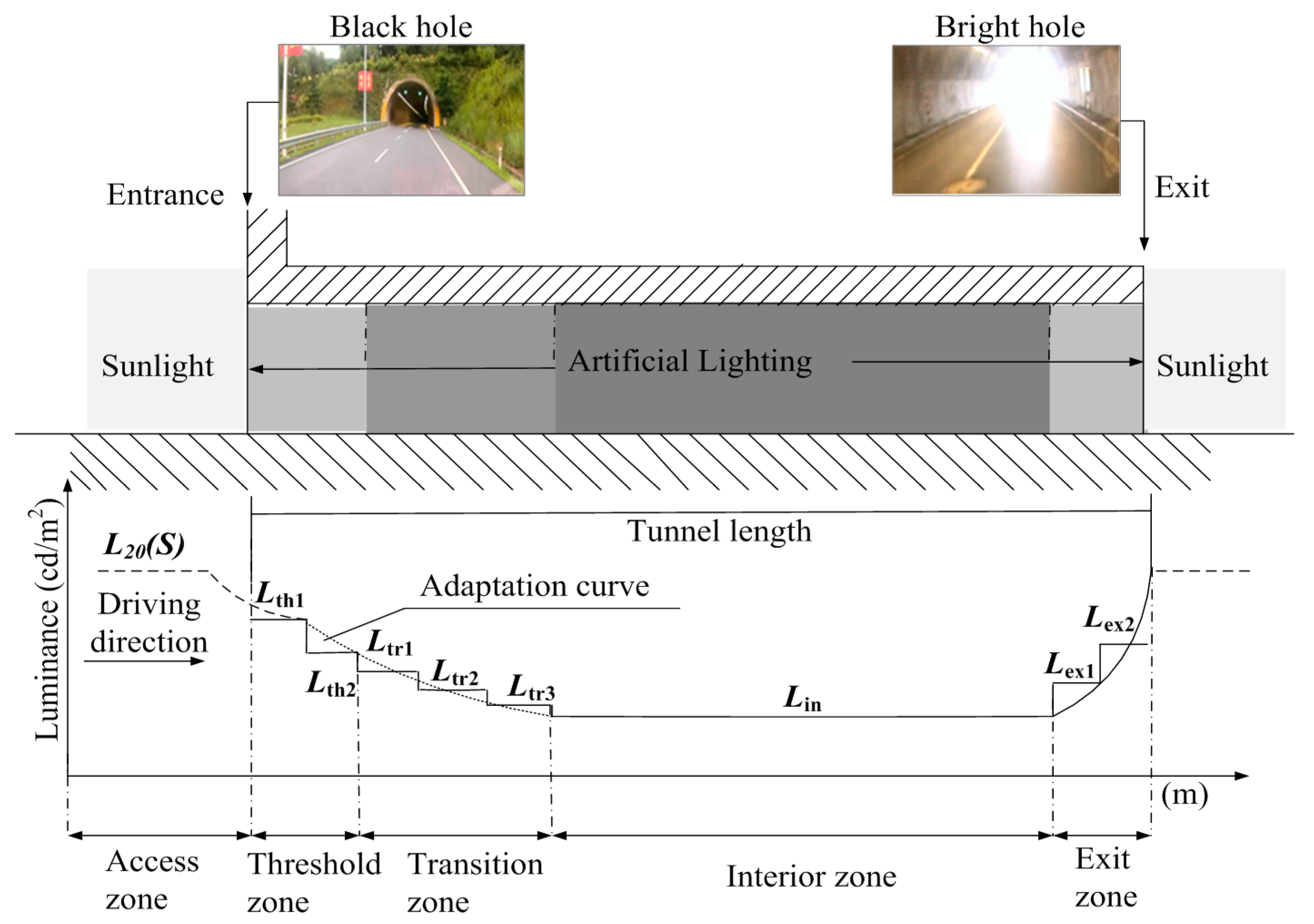
Figure 2.
Entrance to the Chibai tunnel in the direction from Tonghua City to Shenyang City.

Figure 3.
Tunnel lighting control system architecture.

Figure 4.
Vehicle speed percentage distribution for a period of 12 days: (a) Weekday/cloudy to sunny; (b) Weekday/sleet to light rain; (c) Weekday/sunny; (d) Weekend/sunny; (e) Weekday/cloudy; (f) Weekday/sunny to light rain; (g) Weekday/cloudy to light rain; (h) Labor Day in China/light rain to cloudy; (i) Weekday/light rain; (j) Weekday/shower to cloudy; (k) Weekend/sleet to sunny, and; (l) Weekday/moderate rain to light rain.
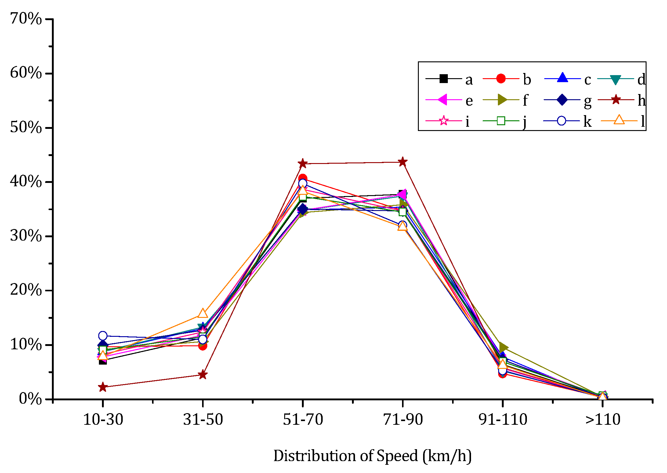
Figure 5.
Traffic volume distribution for a period of 12 days: (a) Weekday/cloudy to sunny; (b) Weekday/sleet to light rain; (c) Weekday/sunny; (d) Weekend/sunny; (e) Weekday/cloudy; (f) Weekday/sunny to light rain; (g) Weekday/cloudy to light rain; (h) Labor Day in China/light rain to cloudy; (i) Weekday/light rain; (j) Weekday/shower to cloudy; (k) Weekend/sleet to sunny, and; (l) Weekday/moderate rain to light rain.

Figure 6.
Average time interval between two consecutive vehicles and total time of light-emitting diodes (LEDs) operating at their lowest luminance level for each hour of the 12 days: (a) Weekday/cloudy to sunny; (b) Weekday/sleet to light rain; (c) Weekday/sunny; (d) Weekend/sunny; (e) Weekday/cloudy; (f) Weekday/sunny to light rain; (g) Weekday/cloudy to light rain; (h) Labor Day in China/light rain to cloudy; (i) Weekday/light rain; (j) Weekday/shower to cloudy; (k) Weekend/sleet to sunny, and; (l) Weekday/moderate rain to light rain.

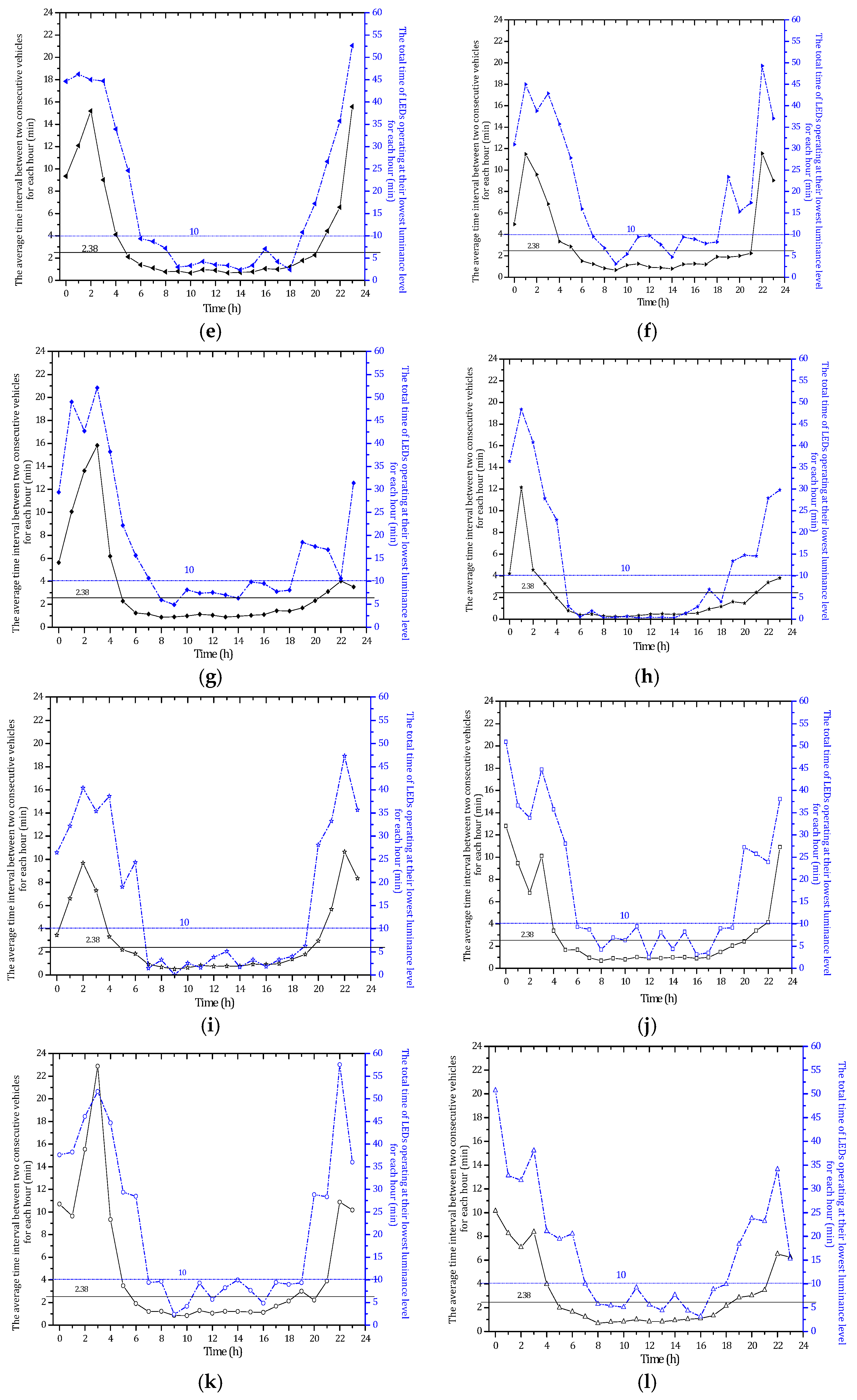
Figure 7.
Schematic of the operation of the tunnel lighting system.

Table 1.
Equations for luminance calculation in the zones shown in Figure 1.
Table 1.
Equations for luminance calculation in the zones shown in Figure 1.
| Tunnel Section | Luminance (cd/m2) |
|---|---|
| Threshold zone 1 | |
| Threshold zone 2 | |
| Transition zone 1 | |
| Transition zone2 | |
| Transition zone 3 | |
| Interior zone | |
| Exit zone 1 | |
| Exit zone 2 |
Notes: Access zone (Lacc); Threshold zone (Lth); Transition zone (Ltr); Interior zone (Lin); Exit zone (Lex). Lth1, Lth2, Ltr1, Ltr2, Ltr3, Lin, Lex1 and Lex2 are luminance of Threshold zone 1, Threshold zone 2, Transition zone 1, Transition zone 2, Transition zone 3, Interior zone, Exit zone 1, and Exit zone 2, respectively; (v) vehicle speed (km/h); (N) traffic volume (veh/(h·ln).
Table 2.
TP1 less than 2.38 min and TP2 less than 10 min for each of the 12 days. Time period when the time interval between two consecutive vehicles (TP1); time period when LEDs are operating at their lowest luminance level (TP2).
Table 2.
TP1 less than 2.38 min and TP2 less than 10 min for each of the 12 days. Time period when the time interval between two consecutive vehicles (TP1); time period when LEDs are operating at their lowest luminance level (TP2).
| Figure | TP1 Less Than 2.38 min | TP2 Less Than 10 min |
|---|---|---|
| Figure 6a | 6:00 a.m.~7:00 p.m. | 7:00 a.m.~7:00 p.m. |
| Figure 6b | 7:00 a.m.~6:00 p.m. | 7:00 a.m.~6:00 p.m. |
| Figure 6c | 6:00 a.m.~6:00 p.m. | 7:00 a.m.~6:00 p.m. |
| Figure 6d | 5:00 a.m.~8:00 p.m. | 7:00 a.m.~6:00 p.m. |
| Figure 6e | 5:00 a.m.~8:00 p.m. | 6:00 a.m.~6:00 p.m. |
| Figure 6f | 6:00 a.m.~9:00 p.m. | 7:00 a.m.~6:00 p.m. |
| Figure 6g | 5:00 a.m.~8:00 p.m. | 7:00 a.m.~6:00 p.m. |
| Figure 6h | 4:00 a.m.~9:00 p.m. | 5:00 a.m.~6:00 p.m. |
| Figure 6i | 5:00 a.m.~7:00 p.m. | 7:00 a.m.~7:00 p.m. |
| Figure 6j | 5:00 a.m.~8:00 p.m. | 6:00 a.m.~7:00 p.m. |
| Figure 6k | 6:00 a.m.~6:00 p.m. | 7:00 a.m.~7:00 p.m. |
| Figure 6l | 5:00 a.m.~6:00 p.m. | 7:00 a.m.~6:00 p.m. |
© 2017 by the authors. Licensee MDPI, Basel, Switzerland. This article is an open access article distributed under the terms and conditions of the Creative Commons Attribution (CC BY) license (http://creativecommons.org/licenses/by/4.0/).
Share and Cite
MDPI and ACS Style
Qin, L.; Dong, L.-L.; Xu, W.-H.; Zhang, L.-D.; Leon, A.S. An Intelligent Luminance Control Method for Tunnel Lighting Based on Traffic Volume. Sustainability 2017, 9, 2208. https://doi.org/10.3390/su9122208
AMA Style
Qin L, Dong L-L, Xu W-H, Zhang L-D, Leon AS. An Intelligent Luminance Control Method for Tunnel Lighting Based on Traffic Volume. Sustainability. 2017; 9(12):2208. https://doi.org/10.3390/su9122208
Chicago/Turabian StyleQin, Li, Li-Li Dong, Wen-Hai Xu, Li-Dong Zhang, and Arturo S. Leon. 2017. "An Intelligent Luminance Control Method for Tunnel Lighting Based on Traffic Volume" Sustainability 9, no. 12: 2208. https://doi.org/10.3390/su9122208
Note that from the first issue of 2016, this journal uses article numbers instead of page numbers. See further details here.