1. Introduction
The low air permeability in coal seams restricts the effectiveness of pre-mining gas extraction and tends to cause significantly high gas concentrations at the upper part of the working space during mining. Such low air permeability carries various risks at the working space. Therefore, the air permeability of the working space should be increased to minimize the risk related to the gas concentration. On the other hand, the air permeability of the fractured zone decreases several hundred times compared to the original air permeability immediately after the mining due to the stress concentrations, and pressurized gas should be extracted properly at this stage [
1,
2,
3,
4]. Pressurized gas has been extracted from goaf mainly through borehole extraction and roadway extraction. Researchers have conducted numerous studies to determine the optimal pressurized gas extracting methods. Li Shugang et al. [
4,
5,
6] reported that pressurized gas accumulates mainly in the fractures in the elliptic–parabolic zones of goaf once the coal seam is mined, and borehole extraction can achieve good extraction results. Yuan Liang and Lu Ping et al. [
7,
8,
9] effectively controlled the levels of gas accumulation and removed the risk in the affected areas through integrating borehole extraction, protected seam mining, and Y-shaped ventilation based on the mining conditions of the low air permeability coal seam groups in Huainan. Liu Hongyong et al. [
10,
11] classified the migration areas of overburden fractures gas and developed an artificial gas diversion method mainly through the use of high drainage roadways as transitional gas migration channels or areas. Liu Zegong et al. [
12] conducted a comprehensive study on the key technologies involved in the extraction of goaf gas through a high roadway as well as the principles of the high roadway layout. In addition to the aforementioned studies, other studies on pressurized gas extraction have been conducted [
13,
14,
15,
16]. Currently, all high drainage roadways are located in the fractured zone beside the air-return roadway. However, each of these high drainage roadways serves only one working face and is discarded after mining.
This paper proposed the layout of a lateral high drainage roadway (LHDR) using borehole-based gas extraction technology. The suggested LHDR can perform two functions: a drainage roadway and extraction of pressurized gas. A theoretical study and numerical simulation were carried out to identify the mining-induced fractures and stress distribution due to mining. Field observations were adopted to determine the layout of the LHDR and derive the optimal final position of the boreholes based on the geological conditions in the Liyazhuang Coal Mine in China. Furthermore, a derived borehole and LHDR were installed at the specified mining site. The rock displacement of the LHDR and gas concentration at the branch pipelines, boreholes of the LHDR, and upper part of working face were monitored during mining, and the performance of the proposed LHDR is validated.
2. Introduction to the Lateral High Drainage Roadway
2.1. Proposed Layout of Lateral High Drainage Roadway
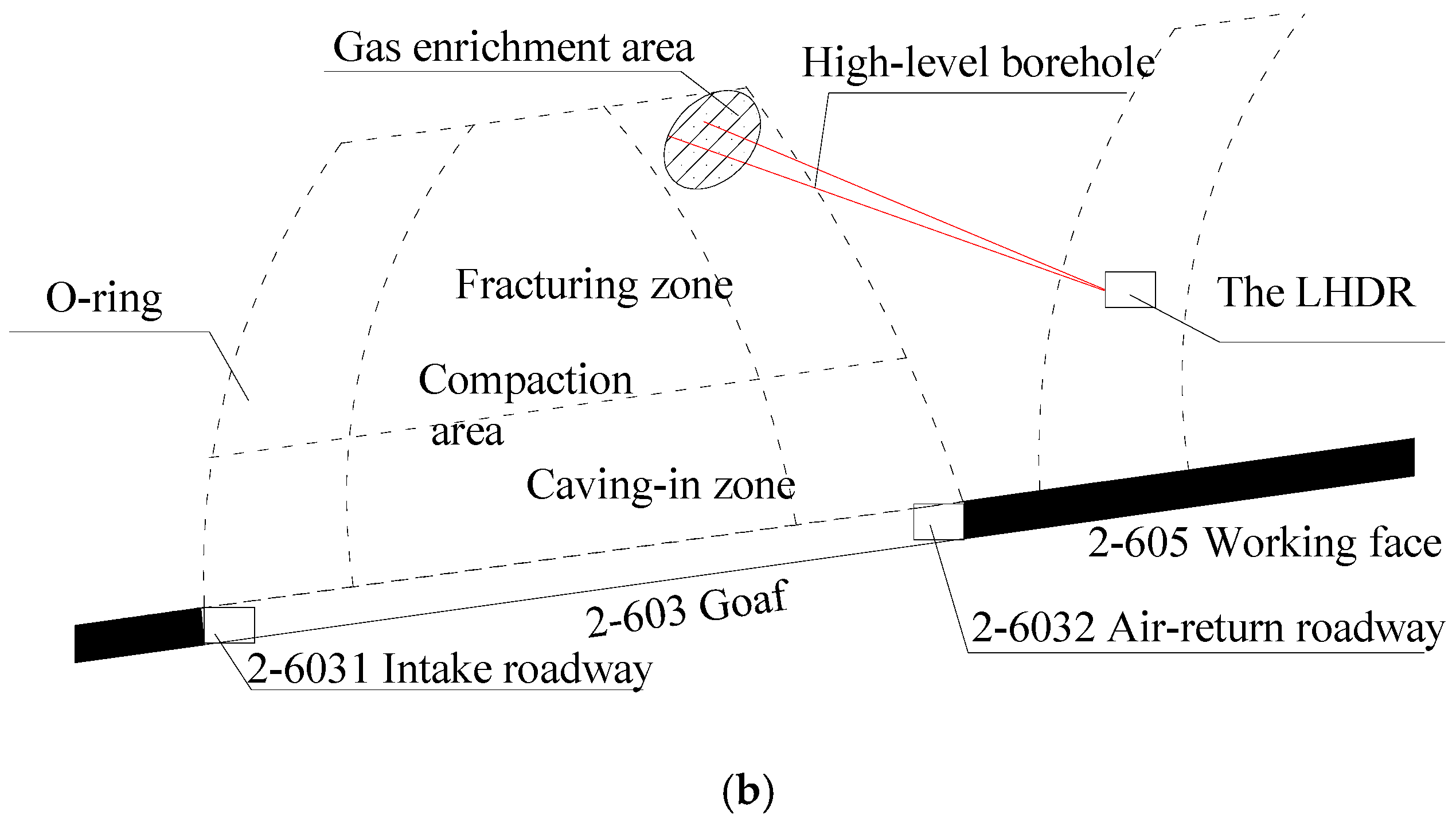
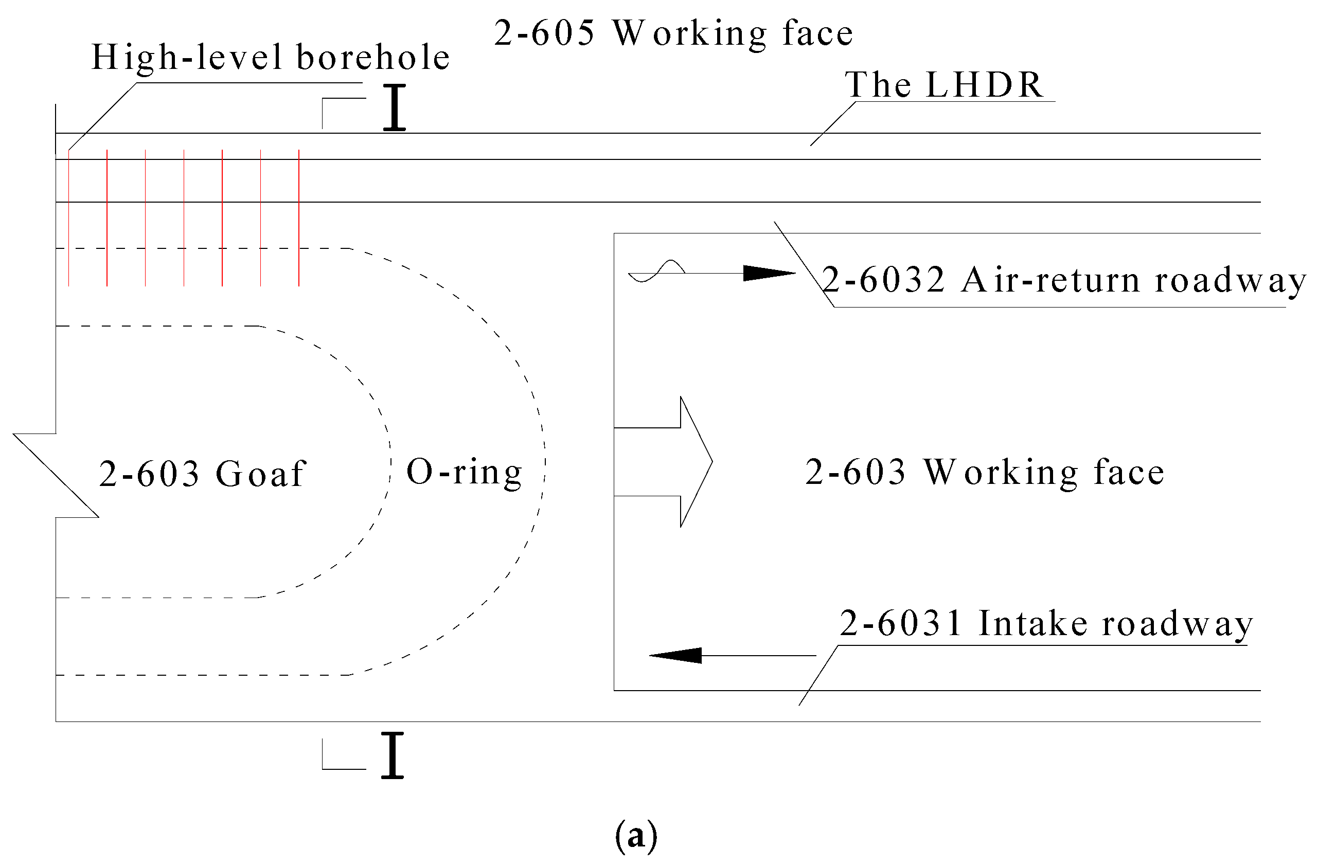
Figure 1 presents the layout of the proposed LHDR considering the geological conditions of the Liyazhuang Coal Mine [
17]. Before the excavation of the 2-603 working face, a LHDR was constructed in the roof strike direction and was dislocated laterally from the 2-603 working face (inwardly dislocated from the 2-605 working face). The boreholes should be installed from the LHDR to fractured zone to extract the pressurized gas during mining at the 2-603 working face. The roadway was then used to extract the pressurized gas from the fractured zone of the 2-605 working face. The high drainage roadway can serve two adjacent working faces within the same coal seam to extract the pressurized gas in the fractured zones, and the gas concentrations of the upper part of the working space can be reduced.
2.2. Key Technical Considerations
The following considerations are important to ensure the effective performance of the LHDR:
- (1)
The stress distribution around the LHDR due to excavation at the working face should be examined carefully considering the geological conditions of the mining site. The stress distribution can provide the theoretical foundation for determining the optimal position of the LHDR and the boreholes for pressurized gas extraction.
- (2)
Because the LHDR serves two adjacent working faces within the same coal seam to extract the pressurized gas, it undergoes two separated mining activities. Therefore, the LHDR should have a reasonable layout. In this study, the roadway should be affected only slightly by mining at the 2-603 working face during the first cycle. The lengths of the high-level borehole should be as short as possible to reduce the amount of drilling work at this stage. During the second cycle, the LHDR should ensure the optimal performance of pressurized gas extraction in the mining-induced overburdened area from the 2-605 working face.
- (3)
For the optimal layout of the LHDR, a determination of the lateral and vertical position of boreholes is essential. The boreholes should be laid out accurately to extract the pressurized gas in the mining-induced overburdened fractures, and to reduce the gas concentrations at the upper part of working face.
The following sections discuss the aforementioned key considerations.
3. Distribution of Fractures and Stress Due to Mining
The 2-603 working face is located in the deepest part of the sixth mining area’s right wing, its southeast part is the coal field’s boundary and its northwest part is the 2-605 working face that has not been mined. The thickness of the coal seam is 3.14–3.70 m, and the dip angle ranges from 5° to 16° (8° on average). A numerical model was established using the commercial software UDEC 2D 4.0 (Itasca Consulting Group, Minneapolis, MN, USA) based on the geological conditions of the 2-603 working face [
17]. The 2-603 and 2-605 working faces presented in
Figure 1 were excavated successively to examine the distribution of fractures and stresses. The distribution characteristics of the fractures and stresses provide a theoretical foundation for the optimal positions of the LHDR and the boreholes for pressurized gas extraction.
3.1. Distribution of Fractures Due to Mining
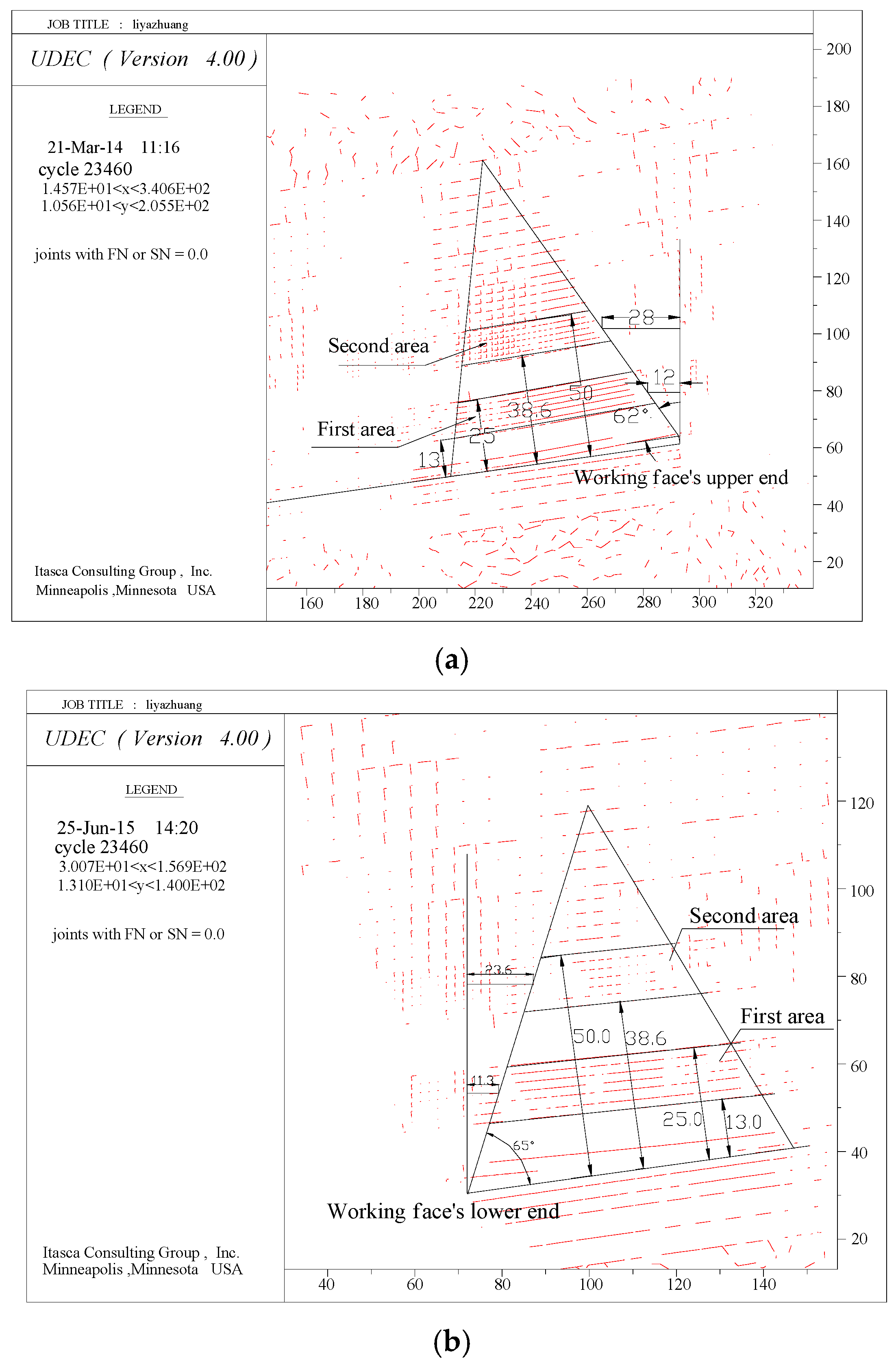
Figure 2 shows the distribution of the mining-induced fractures at the ends of the working face. Horizontal fractures developed mainly 13–25 m away from the floor and 12 m away from the goaf boundary. The fractures area was approximately 65 m wide. Horizontal fractures were also concentrated in the area 38.6–50 m from the floor and 28 m from the goaf boundary. The fractures area was approximately 50 m wide for this layer. Both areas were within the uphill subsidence angle of 62° and downhill subsidence angle of 65°. Therefore, the position of the extraction boreholes should be located above the second area.
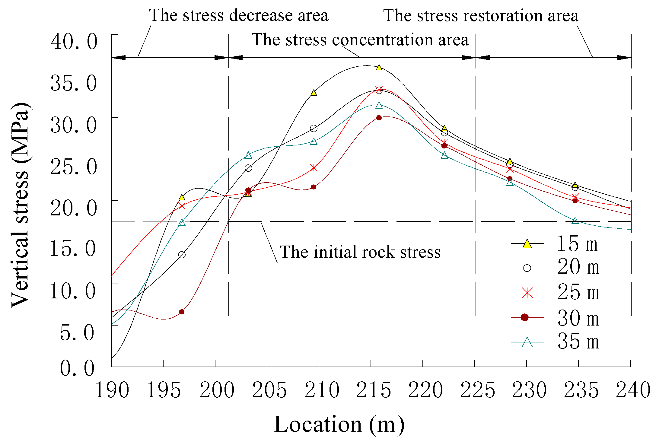
3.2. Distribution of Stress Due to Mining at the Upper End of the Working Face
Figure 3 presents the vertical stress distribution at the upper end of the 2-603 working face. The vertical stress was measured to be 15 m, 20 m, 25 m, and 35 m from the floor. Vertical stress varies according to the location; it initially increases and then decreases with increasing distance from the working face. Owing to mining at the 2-603 working face, stress is released up to 201 m, and the stress is concentrated at the range of 201–225 m due to an arching effect. The peak stress is found approximately 10–15 m from the mining section. The vertical stress decreases rapidly within the range of 215–220 m. As the distance from the mining section increases further, the stress recovers its initial far field stress. In
Figure 3, the vertical stresses are restored gradually to the initial state beyond 240 m.
3.3. Determination of the Lateral High Drainage Roadway Position
3.3.1. Determination of the Lateral Position
As shown in
Figure 3, in order to minimize the effects on mining activities, the LHDR should not be located in the concentrated stress zone. At the same time, the extraction boreholes should be placed behind the working face to reduce the influence on the borehole stability due to mining activities. By considering the vertical stress distribution and the drilling of extraction boreholes at an early stage, the LHDR should be 25 m away laterally from the 2-603 working face. Positioning the LHDR in a relatively low-stress area allows easy maintenance of the LHDR and a decrease in work load induced by extraction borehole drilling.
3.3.2. Determination of the Vertical Position
The performance of the LHDR is dependent on the relative vertical position with respect to the working face. In particular, deformation and the extraction efficiency of the pressurized gas are affected by the vertical position of the LHDR. In this study, three cases were adopted to derive the optimal vertical position of the LHDR with respect to the working face; the vertical position of the LHDR was varied 20, 25, and 30 m from the working face. Rock deformation and the development of fractures due to mining were compared and analyzed for three different vertical positions.
The stress and displacement around the LHDR were obtained. Commonly, the tensile stress develops around the LHDR, and the overall deformation is insignificant due to mining at the 2-603 working face. In addition, deformation is found mainly at the left wall, which is close to the 2-603 working face, and the floor of the LHDR. For all cases, the vertical position satisfies the requirement for the extraction of pressurized gas from the 2-605 working face.
The behavior of the LHDR is affected significantly by mining at the 2-605 working face depending on the vertical distance. When the distance from the LHDR to the working face is 20 m, the LHDR is located between the 9 m-thick medium-grained sandstone layer and the 12 m-thick powder sandstone layer, and the LHDR can communicate well with the overburdened fractured zone. This is a favorable condition for the extraction of pressurized gas.
When the distance is 25 m, the LHDR is located in the upper zone between the 9 m-thick medium-grained sandstone layer and the 12 m-thick powder sandstone layer, and the LHDR can communicate completely with the overburdened fractured zone because the 12 m-thick powder sandstone facilitates gas accumulation and extraction.
When the LHDR is located 30 m above the working face, the LHDR is situated in the 12 m-thick powder sandstone layer and has difficulties for communication with the overburdened fractured zone. Therefore, this case is unfavorable for the extraction of pressurized gas.
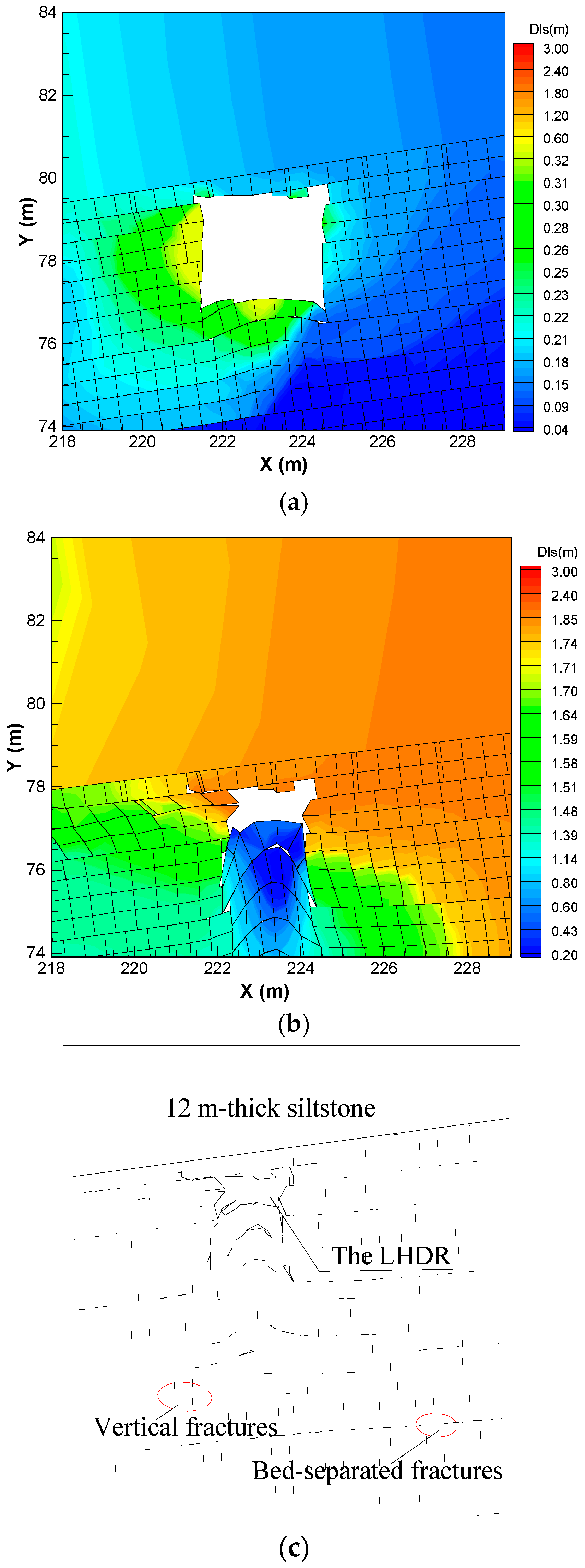
Figure 4 presents the rock deformations and development of fractures due to mining when the vertical position is 25 m from the 2-605 working face.
Based on the case study, the optimal vertical position of the LHDR can be obtained. In this particular site, when the vertical displacement from the working face to LHDR is 25 m, the rock deformation due to two separated mining activities is minimal, and the 12 m-thick powder sandstone layer is favorable for the extraction of pressurized gas.
3.3.3. Optimal Layout of the Lateral High Drainage Roadway
To obtain the reasonable position of the LHDR with respect to the working space, analyses of the mining-induced fractures and stress distribution as well as the communicability should be considered carefully. The optimal LHDR layout obtained in this study was as follows. The LHDR should be located in the roof strike of the 2-603 working face, 25 m away from the 2-603 working face in the lateral direction, and 25 m above the 2-605 working face in the vertical direction.
4. Field Application
4.1. Layout of LHDR and Extraction Borehole
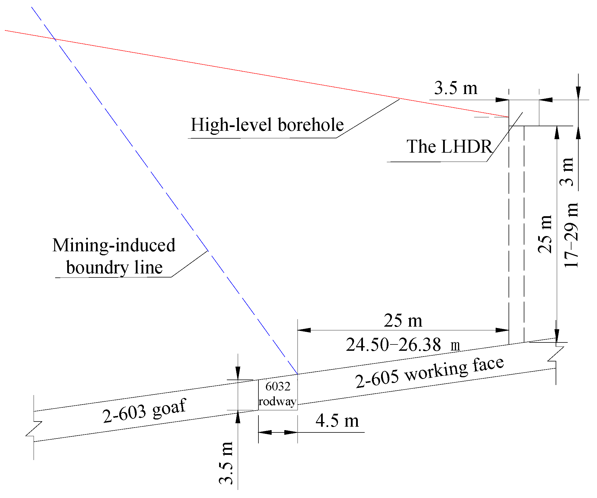
The height and width of the rectangular LHDR is 3 and 3.5 m, respectively. The LHDR is located approximately 25 m from the 2-603 working face, as shown in
Figure 5, and the high drainage roadway is excavated parallel to the 2-603 air-return roadway. Based on the result obtained from a numerical study, the bottom of the high drainage roadway is situated approximately 17 m to 29 m away from the 2-605 working face. An extraction pipeline system (1420 m-long and 280 mm in diameter) was established along the LHDR. The control valve and an orifice flow meter are equipped at both ends of the pipeline for monitoring.
Figure 5 shows the layout of the LHDR.
4.2. Optimization of the Extraction Borehole Position
4.2.1. Layout of Extraction Boreholes
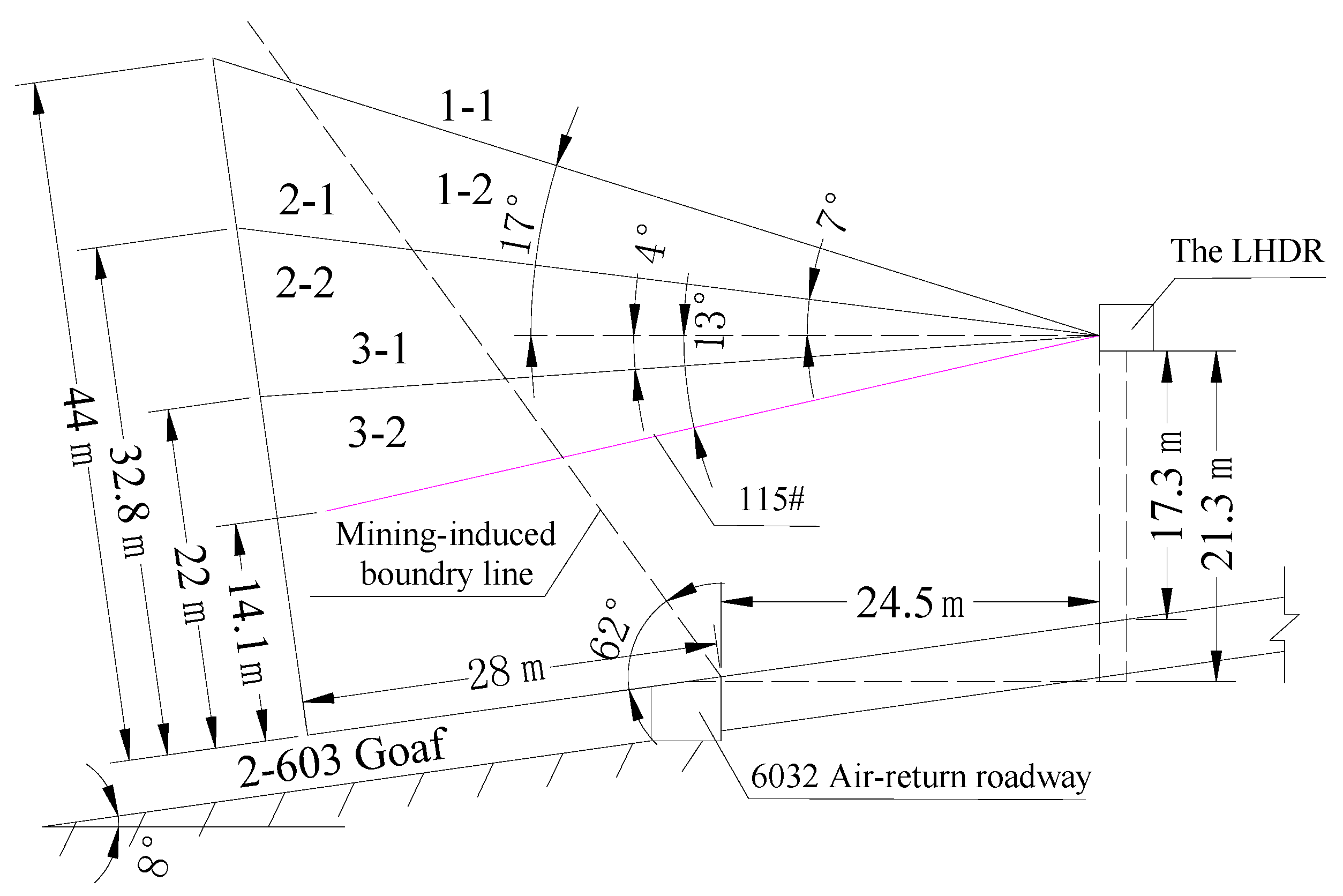
Test extraction boreholes were placed 15 m behind the working face to determine a reasonable location for the extraction boreholes. Six test boreholes were installed in the vicinity of borehole 115# in the LHDR. For boreholes 1-1 and 1-2, the dip angle, length, and height (distance from the final position of the boreholes from the coal seam roof) was 17°, 61 m, and 44 m, respectively. For boreholes 2-1 and 2-2, dip angle, length, and height was 7°, 57 m, and 32.8 m, respectively. For boreholes 3-1 and 3-2, dip angle, length, and height was −4°, 55 m, and 22 m, respectively. The projection of the boreholes onto the goaf should be longer than 28 m. The six boreholes were laid out in a fan shape at 5 m intervals. The opening position of test borehole is located 1 m above the floor of LHDR. The diameter of test boreholes was 133 mm.
Figure 6 presents the layout of the test boreholes.
4.2.2. Variation of Gas Concentration
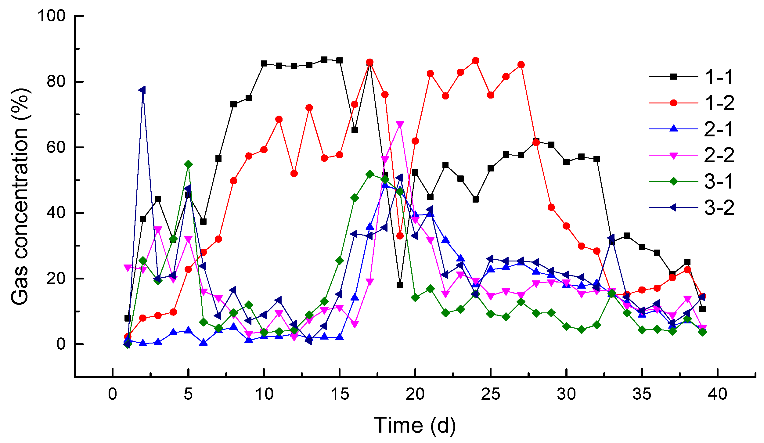
The concentration of gas was monitored for 40 days and its variation is presented in
Figure 7 for six test boreholes. The gas concentration obtained from boreholes 1-1 and 1-2 was outstanding compared to the other test boreholes. Approximately 40 days were needed to reduce the gas concentration using extraction boreholes.
For boreholes 1-1 and 1-2, the number of days when the gas concentration is higher than 80% are 12 and 13, respectively, and the numbers of days when the gas concentration ranges from 50% to 80% are 17 and 3, respectively. For boreholes 2-1 and 2-2, the number of days when the gas concentration is higher than 30% is 6. For boreholes 3-1 and 3-2, the number of days when the gas concentration is higher than 30% is 6 and 7, respectively. Therefore, the design of test boreholes 1-1 and 1-2 is reasonable.
5. Validation for the Performance of Proposed LHDR
5.1. Rock Deformation of Lateral High Drainage Roadway Due to Mining
The deformation of the LHDR was monitored from six stations during mining at the 2-603 working face.
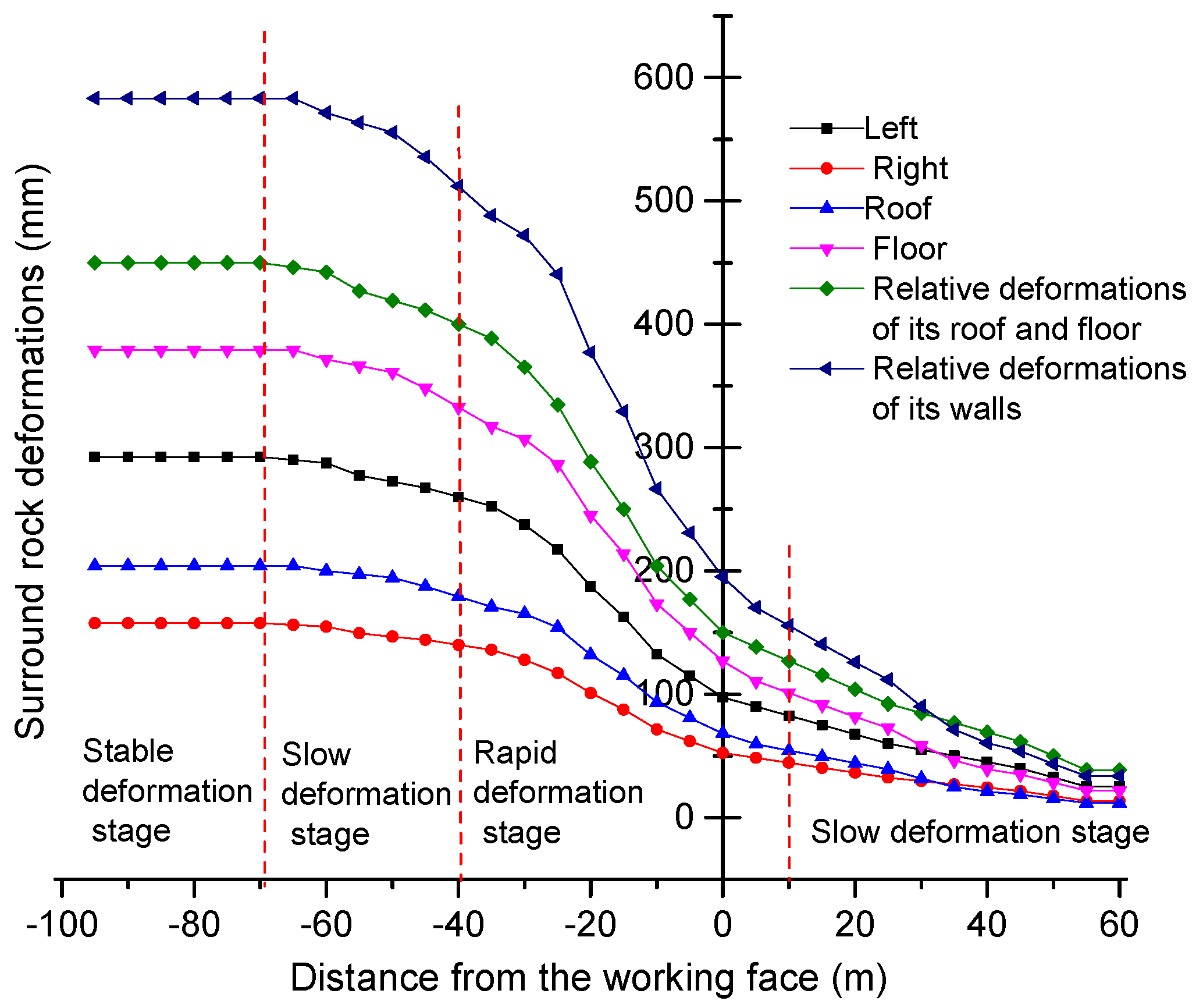
Figure 8 presents the deformation obtained from the second station. The deformation of the LHDR is closely related to the advancement of the 2-603 working face, and it is significant at the left wall and floor of the LHDR. Four deformation stages were observed: slow deformation stage, rapid deformation stage, slow deformation stage, and stable deformation stage. The LHDR showed slow deformation until the working face was far beyond three times the LHDR width. Rapid deformation occurred approximately 10–11 times the LHDR width behind the working face due to mining. As the distance from the working face increases, it transforms to a second slow deformation stage. The deformation of LHDR reaches the stable condition 20 times of the LHDR width behind the working face. When the rock deformation converges to stable condition, the relative deformation in the walls and in the roof and floor of the LHDR were 583 and 450 mm, respectively. Although the deformation at the left wall and floor was significant and the shrinkage ratio ranged from 21.52% to 25.32%, the deformation converges to the stable condition. This suggests that the deformations in the LHDR were acceptable with regard to mining at the 2-603 working face.
5.2. Effect of Borehole Extraction
The bottom of the high drainage roadway is situated approximately 17 m to 29 m away from the 2-605 working face. The angles of the extraction boreholes of the LHDR should be adjusted in the real-time, so as to ensure that the final boreholes would be 44 m above the second coal seam’s roof, and the projections of the boreholes in the goaf shall be at least 28 m long. The boreholes are drilled 15 m behind the working face, at intervals of 1.8 m and with their openings 1.0 m away from the bottom board of the LHDR.
During mining at the 2-603 working face, the gas concentration was monitored every day at the branch pipelines, boreholes of the LHDR, and upper part of the working face. From the continuous monitoring data over a 13 month period, the gas flow rate in the branch pipelines was 90 m3/min, and the pure gas flow rates were 16.6–28.3 m3/min and 22.3 m3/min on average. Furthermore, the gas concentration ranges from 18.4% to 31.4%, and 24.8% on average. The extraction branches were connected to 15–20 boreholes. For these boreholes, the extraction durations can reach up to 20–40 days, and the gas concentrations vary between 10% and 65%. The ratios of the numbers of days when the gas concentration was at least 50% to the total number of extraction days ranged from 16% to 36%. The ratios of the numbers of days when the gas concentration was 30%–50% to the total number of extraction days ranged from 23% to 50%.
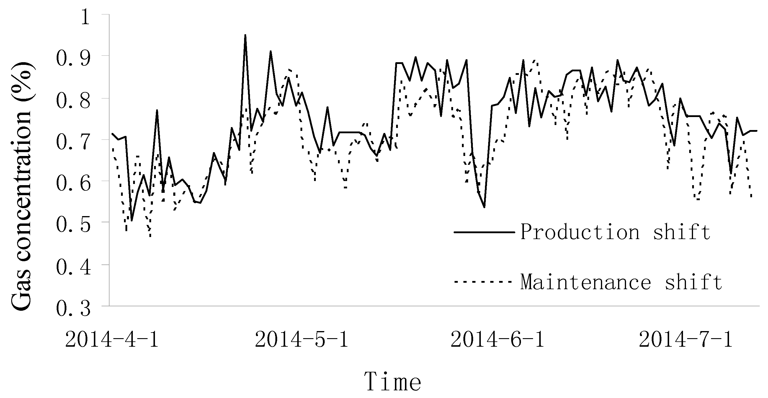
The gas concentration was measured at the upper part of the working face after commencing the project since April 2014. The gas concentrations varied from 0.50% to 0.95% for the production shift and 0.47% to 0.89% for the maintenance shifts, respectively.
Figure 9 shows the variation of the gas concentration from April to July 2014. The results show that the gas concentration at the upper part of the working face was reduced significantly. Therefore, extremely high gas concentrations are avoided and a safe working face is obtained.
6. Conclusions
To improve the sustainability at the mining site, a new drainage roadway that can serve two adjacent working faces was proposed. A schematic layout of the proposed LHDR was presented. The LHDR suggested in this study can be used to extract pressurized gas from two neighboring mining zones.
A theoretical study, numerical simulation, and field observations were performed to identify the mining-induced fractures and stress distribution to the optimal layout of the LHDR. The layout of the LHDR was derived considering the geological conditions in the Liyazhuang Coal Mine in China. The LHDR should be located in the roof strike of the 2-603 working face, 25 m away from the 2-603 working face in the lateral direction, and 25 m above the 2-605 working face in the vertical direction.
In addition, the optimal position of the extraction boreholes was obtained from a field test. From the monitoring data of the gas concentration, boreholes with a 17° dip angle, 61 m long and 44 m above the coal seam roof showed the best performance.
To validate the derived borehole position and LHDR layout, the LHDR and extraction borehole were installed at the specified mining site, and the rock displacement of LHDR and gas concentration at the branch pipelines, boreholes of the LHDR, and upper part of the working face were monitored during mining. Although the deformation at the left wall and floor close to the working face was significant, the deformation converged to a stable condition. The highly concentrated pressurized gas flowed continuously through the branch pipelines and boreholes of the LHDR. Moreover, the gas concentration at the upper part of the working face can be reduced significantly.
Acknowledgments
This research was supported by the National Basic Research Program of China (973 Program) (No. 2015CB251600); the National Natural Science Foundation of China (No. 51674188, No. 51504182, No. 51327007), the Natural Science Basic Research Plan in Shaanxi Province of China (No. 2015JQ5187), the Scientific Research Program Funded by Shaanxi Provincial Education Department (No. 15JK1466), and the Project funded by China Postdoctoral Science Foundation (No. 2015M582685). This research was supported by Development of Design and Construction Technology for Double Deck Tunnel in Great Depth Underground Space(14SCIP-B088624-01) from Construction Technology Research Program funded by Ministry of Land, Infrastructure and Transport of Korean government.
Author Contributions
Shu-gang Li and Hai-qing Shuang conceived the research. Hai-qing Shuang analyzed the data and wrote the paper. Hong-sheng Wang, Ki-Il Song and Lang Liu participated in the design of the study and verified the results. All authors have read and approved the final manuscript.
Conflicts of Interest
The authors declare no conflict of interest.
References
- Yuan, L. Theory and practice of integrated coal production and gas extraction. J. Coal Sci. Eng. 2015, 2, 3–11. [Google Scholar] [CrossRef]
- Wang, H.; Cheng, Y.; Wang, L. Regional gas drainage techniques in Chinese coal mines. Int. J. Min. Sci. Technol. 2012, 22, 873–878. [Google Scholar]
- Yuan, L. Key technique of safe mining in low permeability and methane-rich seam group. Chin. J. Rock Mech. Eng. 2008, 27, 1370–1379. (In Chinese) [Google Scholar]
- Li, S.; Xiao, P.; Pan, H. Experimental investigation on the seepage law of pressure-relieved gas under the influence of mining. Saf. Sci. 2012, 50, 614–617. [Google Scholar] [CrossRef]
- Lin, H.; Li, S.; Cheng, L. Experiment alanalysis of dynamic evolution model of mining-induced fissure zone in overlying strata. J. Min. Saf. Eng. 2011, 28, 298–303. (In Chinese) [Google Scholar]
- Li, S.; Lin, H.; Zhao, P. Dynamic evolution of mining fissure elliptic paraboloid zone and extraction coal and gas. J. China Coal Soc. 2014, 38, 1455–1462. (In Chinese) [Google Scholar]
- Xue, S.; Yuan, L.; Xie, J. Advances in gas content based on outburst control technology in Huainan. China Int. J. Min. Sci. Technol. 2014, 24, 385–389. [Google Scholar] [CrossRef]
- Lu, P.; Li, P.; Chen, J.; Zhang, C. Gas drainage from different mine areas: Optimal placement of drainage systems for deep coal seams with high gas emissions. Int. J. Coal Sci. Technol. 2015, 2, 84–90. [Google Scholar] [CrossRef]
- Lu, P.; Yuan, L.; Chen, H. Theory and experimental studies of enhanced gas drainage in the high gas face of low permeability coal multi-seams. J. China Coal Soc. 2010, 35, 580–585. (In Chinese) [Google Scholar]
- Liu, H.; Cheng, Y.; Zhou, H. Fissure evolution and evaluation of pressure-relief gas drainage in the exploitation of super-remote protected seams. Min. Sci. Technol. 2010, 20, 178–182. [Google Scholar] [CrossRef]
- Liu, H.; Cheng, Y.; Chen, H. Characteristics of mining gas channel expansion in the remote overlying strata and its control of gas flow. Int. J. Min. Sci. Technol. 2013, 23, 481–487. [Google Scholar] [CrossRef]
- Liu, J.; Liu, Z.; Xue, J. Application of deep borehole blasting on fully mechanized hard top-coal pre-splitting and gas extraction in the special thick seam. Int. J. Min. Sci. Technol. 2015, 25, 755–760. [Google Scholar] [CrossRef]
- Lin, H.; Li, S.; Suo, L. Numerical simulation on reasonable position of strike high roadway with FLUENT. J. Liaoning Tech. Univ. (Nat. Sci.) 2014, 33, 172–176. (In Chinese) [Google Scholar]
- Lou, J. Research on the Deformation Mechanism and the Location Optimization of High-Level Entry for Gas Extraction. Master's Thesis, China University of Mining & Technology, Xuzhou, China, 2008. [Google Scholar]
- Liu, L.; Cheng, Y.; Wang, H. Principle and engineering application of pressure relief gas drainage in low permeability outburst coal seam. Min. Sci. Technol. 2009, 19, 342–345. [Google Scholar] [CrossRef]
- Xie, S.; Zhao, Y.; Zhang, S. Mechanism and experiment of substituting high drainage roadway with directional long drilling group to extract pressure-relief gas. J. Cent. South Univ. 2012, 19, 2591–2597. [Google Scholar] [CrossRef]
- Shuang, H.; Wang, H.; Li, S. High level borehole drainage technique of the overlying strata mining-induced press-relief gas. J. Xi’an Univ. Sci. Technol. 2015, 35, 682–687. (In Chinese) [Google Scholar]
© 2017 by the authors. Licensee MDPI, Basel, Switzerland. This article is an open access article distributed under the terms and conditions of the Creative Commons Attribution (CC BY) license ( http://creativecommons.org/licenses/by/4.0/).


