
Cooperative Downlink Listening for Low-Power Long-Range Wide-Area Network

1
Creative Informatics & Computing Institue, Korea University, Seoul 02841, Korea
2
Department of Embedded Systems Engineering, Incheon National University, Incheon 22012, Korea
*
Author to whom correspondence should be addressed.
Sustainability 2017, 9(4), 627; https://doi.org/10.3390/su9040627
Submission received: 31 March 2017
/
Revised: 7 April 2017
/
Accepted: 12 April 2017
/
Published: 17 April 2017
(This article belongs to the Collection Advanced IT based Future Sustainable Computing)
Abstract
:Recently, the development of the Internet of Things (IoT) applications has become more active with the emergence of low-power wide-area network (LPWAN), which has the advantages of low-power and long communication distance. Among the various LPWAN technologies, long-range wide-area network (LoRaWAN, or LoRa) is considered as the most mature technology. However, since LoRa performs uplink-oriented communication to increase energy efficiency, there is a restriction on the downlink function from the network server to the end devices. In this paper, we propose cooperative downlink listening to solve the fundamental problem of LoRa. In particular, the proposed scheme can be extended to various communication models such as groupcasting and geocasting by combining with the data-centric model. Experiments also show that the proposed technology not only significantly reduces network traffic compared to the LoRa standard, but also guarantees maximum energy efficiency of the LoRa.
1. Introduction
Over the last decades, rapid advances in low-cost low-power wireless communication technologies have accelerated the development of the Internet of Things (IoT) applications and services. These wireless technologies are generally based on short range communication such Bluetooth low energy (BLE), IEEE 802.15.4, and Wi-Fi (IEEE 802.11). However, the range limitation of IoT applications based on these communication technologies has made communication links unreliable and thus it has led to the degradation of communication reliability. Therefore, the demand for wide communication coverage is increased. Finally, these strong demands have led to the advent of low-power, long-range wireless communication systems, called low-power wide-area network (LPWAN). Various research groups are developing new LPWAN systems based on the new standards. These include long-range wide-area network (LoRaWAN) [1] by the LoRa Alliance, Long Term Evolution for machine to machine (LTE-m) [2] and Narrow Band Internet of Things (NB-IoT) [3] by 3GPP, ultra-narrow band communication by Sigfox [4], etc. Among these new technologies, LoRa is widely being accepted as the most promising LPWAN technologies in terms of power efficiency, low-cost chipset, and regional ISM bands. One of the key technologies of LoRa is to use chirp spread spectrum (CSS) for modulation, while the legacy low-power communications are based on frequency shift keying (FSK) to achieve low-power. For decades, the CSS modulation has been used in specific areas such as space communications or the military, since it has advantages of long communication capability and robustness to interference. That is, the LoRaWAN has long-range characteristics while maintaining robustness to interference.
Due to its advantages, interesting applications [5,6,7] are already being introduced based on LPWAN; the LoRaWAN has also attracted many researchers. Adelantado et al. [8] revealed the capabilities and limitations of LoRaWAN. In particular, they emphasized that the following challenges should be addressed: new multiple access mechanism and energy efficient multi-hop solution. Mikhylov et al. [9] presented the results of an analysis of LoRaWAN in terms of uplink throughput and data transmission time. According to the results, LoRaWAN duty-cycle-based Medium Access Control (MAC) scheme may increase packet collision probability and delay. In addition, they also showed that LoRaWAN has critical drawbacks in reliability and delay, especially in terms of downlink traffic. Kim et al. [10] pointed out some problems of LoRa gateway capability, and proposed new data transmission network architecture for long-range sensor networks, which are based on a hybrid approach combining LoRa infrastructure and sensor networks. Taneja et al. [11] proposed the hybrid network architecture of LoRaWAN and 802.11ah, and Schroder et al. [12] also proposed LoRaWAN use for smart grid network instead of RF mesh networks (Wi-SUN). Toussaint et al. [13] proposed a Markov chain model of the OTAA. They analyzed the impact of several parameters on traffic conditions, duty cycles, and channel availability. Petajajarvi et al. [14] studied the indoor performance of LoRaWAN based on health and well-being monitoring equipment. The authors also studied the coverage of LoRaWAN [15]. According to the results, the maximum communication range is over 15 km on ground and close to 30 km on water. Pham et al. [16] designed a low-cost DIY LoRa gateway which has a number of functionalities.
Even though LoRaWAN has several advantages including low-power and long-range capability, it also has some limitations and problems as already discussed in several literatures [5,6,7]. In particular, a key problem arises from the class A for the low-power operation of end device. Therefore, in this paper we first point out the limitations and problems of downlink communication in LoRa class A, and then propose a cooperative downlink listening (CDL) algorithm, which can solve the downlink limitations of class A while maintaining low-power characteristics. In addition, we also propose various data-centric models such as groupcasting and geocasting, based on CDL.
The major contribution of this paper is that we propose a novel algorithm to enhance downlink availability which is considered the most critical drawback of LoRa class A. Nevertheless, the new algorithm and protocol are designed compatible with the LoRa standard. In addition, we also open the new area of a data-centric IoT model for LPWAN, which is introduced in wireless sensor networks.
The remainder of this paper is organized as follows: Section 2 presents the technical overview and limitations of LoRaWAN. In Section 3, to address the problem, a new algorithm, CDL, is presented. In Section 4, IoT data-centric models associated with CDL are introduced. The performance evaluation of the proposed algorithm is presented in Section 5. Finally, this paper concludes with Section 6.
2. Overview of LoRaWAN
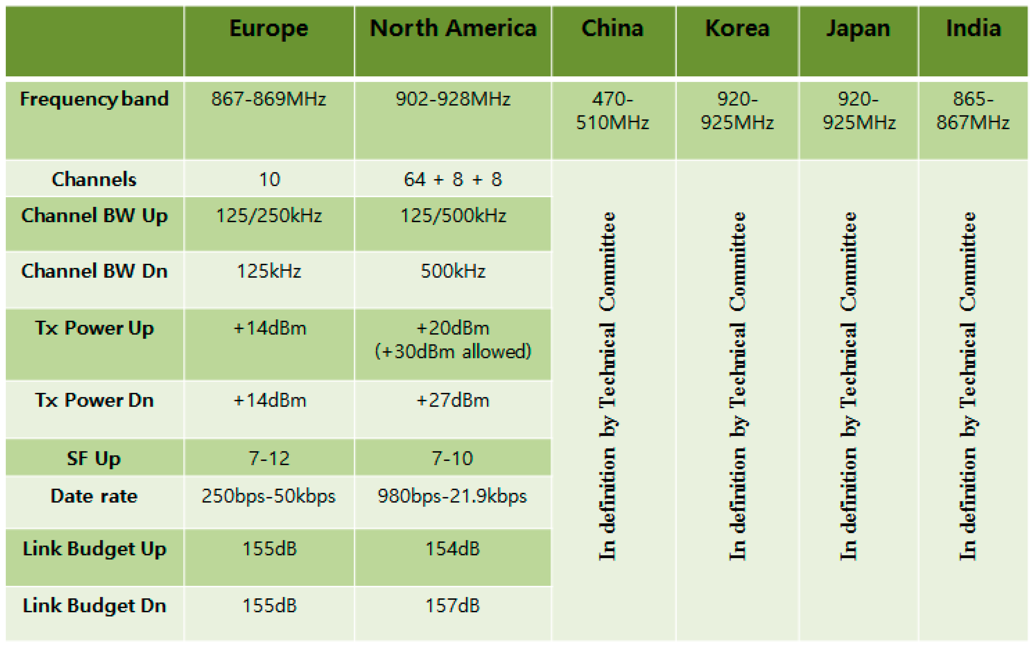
Long-range wide-area networks (LoRaWANs) specify a physical (PHY) and medium access control (MAC) layer protocol for an extremely long-range and low-power network, which is standardized by LoRa alliance. The major advantage of LoRa is in the long-range capability. According to LoRa Whitepaper [17], entire cities or hundreds kilometers in radius can be covered by a single LoRa base station or LoRa gateway. Using chirp spread spectrum (CSS), LoRa can significantly increase communication range while maintaining robustness to interference. These characteristics are attractive for many IoT applications, and many regions and countries are trying to accept the LoRa technology on their regional ISM band. Figure 1 shows the LoRa regional spectrum usage.
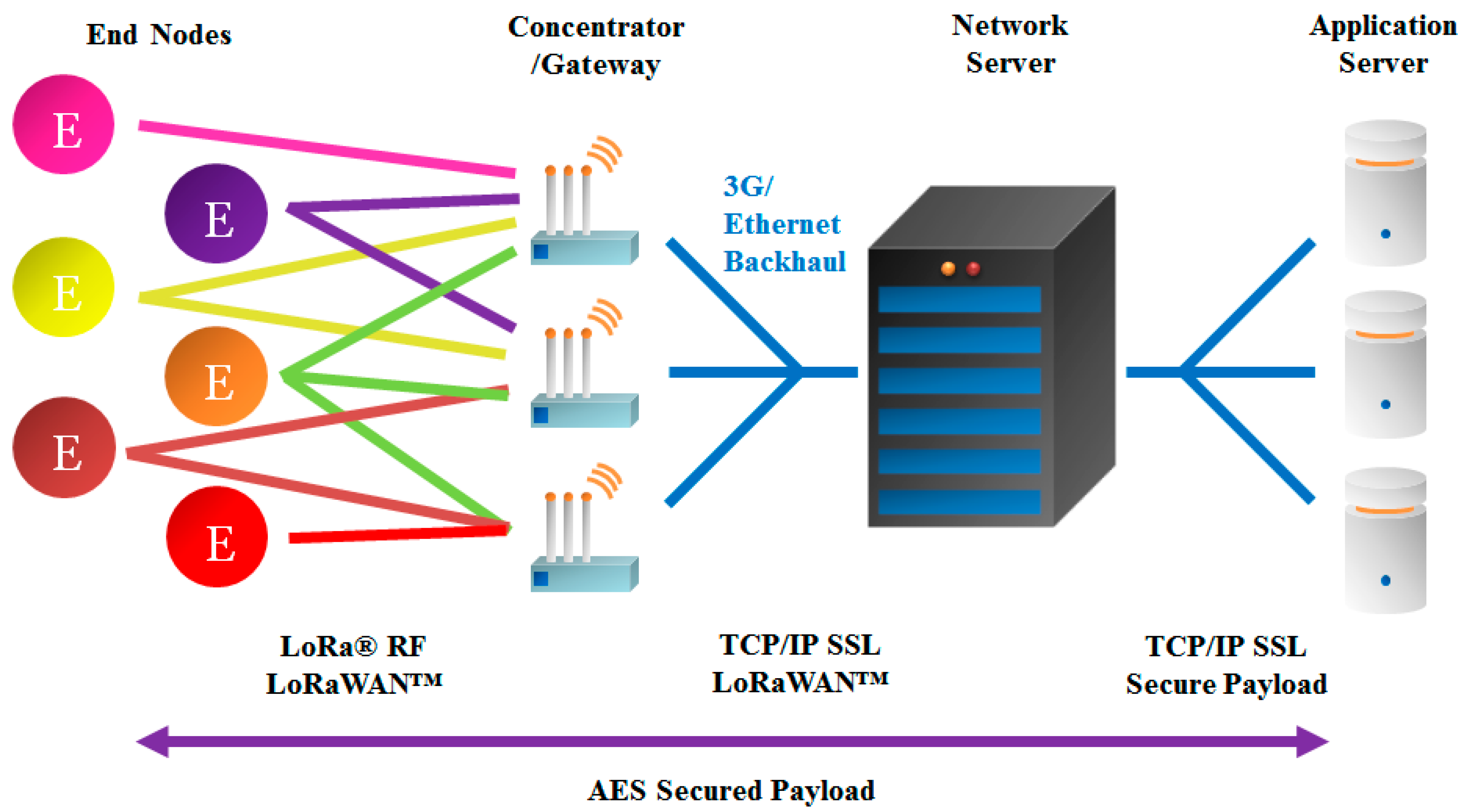
One of the outstanding features of LoRaWAN is based on a star topology connected to the network server in which gateways play a role in relaying messages between end devices and the network server as shown in Figure 2. Gateways have two independent communication links: LoRa communication and IP backhaul. The supported data rates are 0.3–50 kbps. In addition, LoRa provides an adaptive data rate (ADR) function.
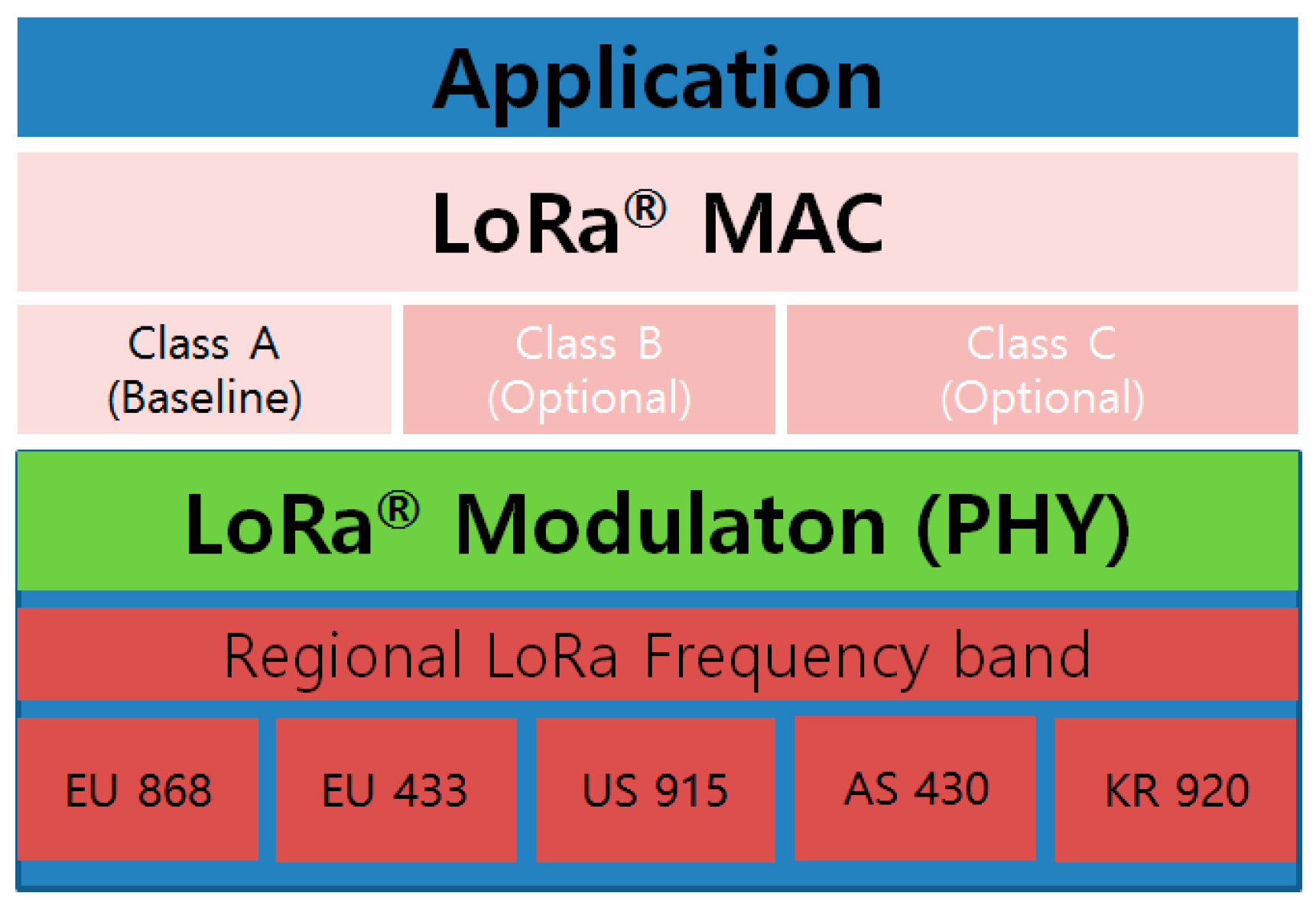
Figure 3 shows LoRa protocol stack (PHY and MAC). Based on regional ISM band, physical layer includes LoRa modulation, and according to application characteristics, MAC has three different classes: Class A (baseline), Class B and C (optional). Class A is used for the low-energy end devices and allows bi-directional communication between end devices and network server. However, downlink communication from network server to each end device is only allowed shortly after the end of uplink transmission of an end device.
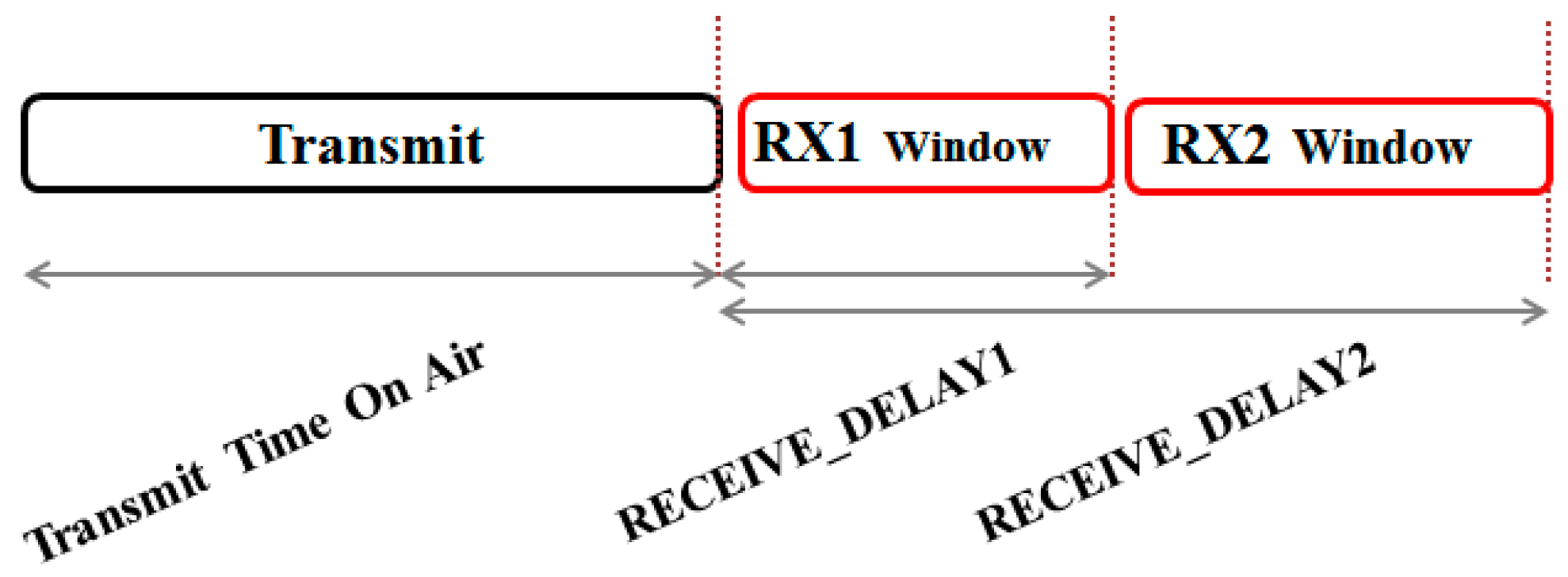
As shown in Figure 4, shortly after uplink transmission, the end device allows two RX windows 1 and 2 during RECEIVE_DELAY1 and 2, respectively. For RX1 window, the same channel and data rate as those used in uplink transmission are used, but RX2 window is allowed to use a different channel and data rate from the uplink transmission.
LoRaWAN has two different types of join methods: over-the-air activation (OTAA) and activation by personalization (ABP). OTAA is an automatic join process performed during deployment of nodes and ABP is a manual join process.
The DevAddr is composed of a 32-bit identifier in which seven bits are used as the network identifier (NwkID) and 25 bits are used as the network address (NwkAddr) which is assigned to each end device by a network manager.
3. CDL: Cooperative Downlink Listening
LoRa defines different classes for low-power long-range characteristics, and enables to use the appropriate class according to the requirements of applications. Since most IoT applications operate with battery, LoRa class A is considered as a MAC layer for most applications. Class A enables end devices to transmit data uplink to the network server via gateway, but it also has some limitations and problems for the data reception downlink from network server. In this section, in order to address limitations and problems with LoRa class A, a cooperative downlink listening algorithm is proposed.
3.1. Limitations and Problems of LoRaWAN Downlink Communication
To minimize power consumption, end devices in class A perform uplink-oriented data transmission as already shown in Figure 4. This approach has an advantage of minimizing power consumption by allowing the device to wake up at some events or scheduled time, transmit data, and then go to sleep mode. However, this approach has a problem with downlink communication from network server to each end device. That is, for the reception downlink from network server, each end device should wait until its own uplink data transmission to network server is completed, and the downlink communication is only available by RX window1 and window2 followed by uplink transmission. Furthermore, in the approach, downlink broadcasting is not possible.
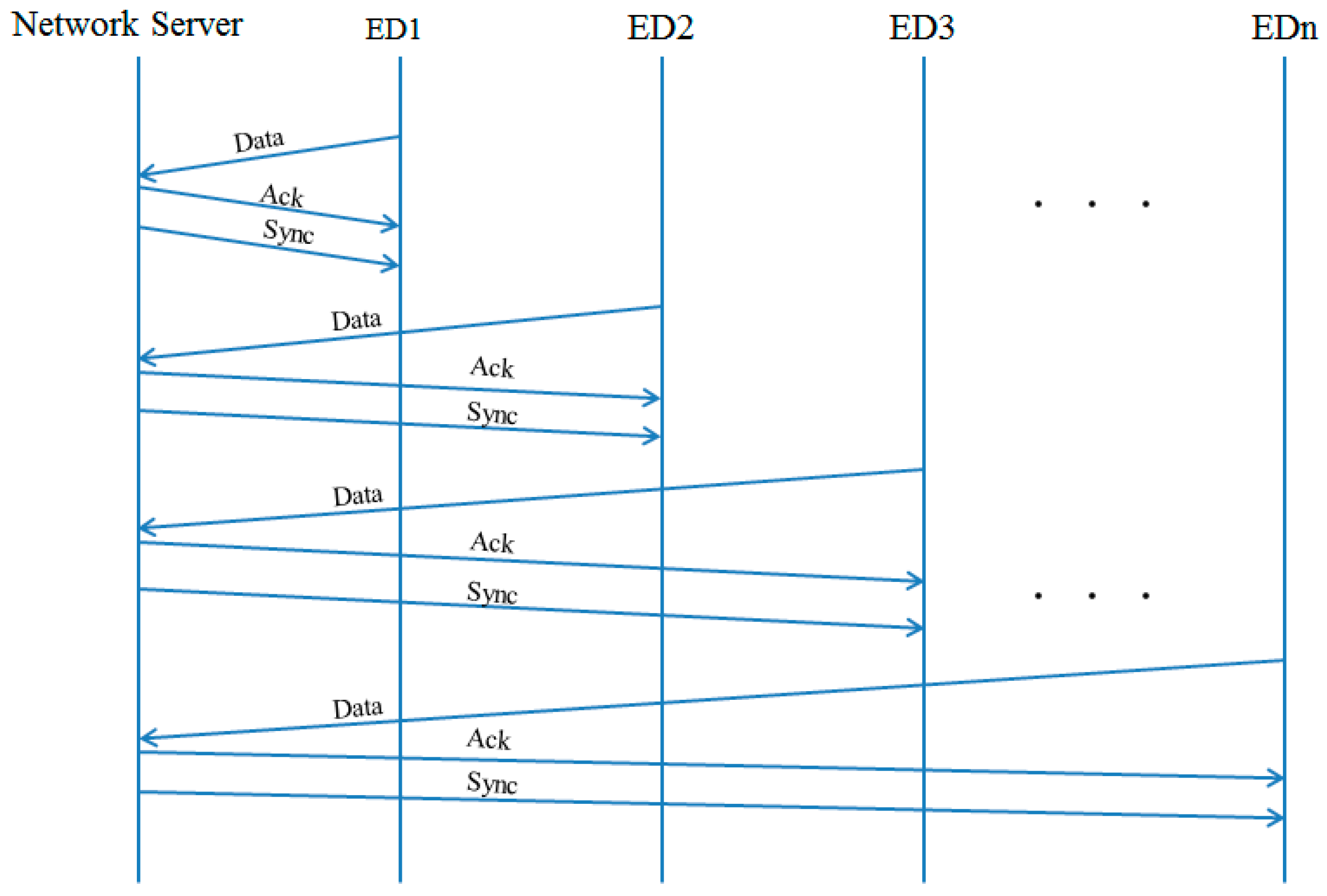
In general, end devices transmit sensing data periodically to the network server. In this case, time synchronization between devices and the network server is required. Such time synchronization tasks should be not often but periodically executed. In the case of LoRa standard (class A), for all end devices to be synchronized with network server, the only way is to use its own RX window followed by individual uplink data transmission. However, this results in significant traffic increase in the network as shown in Figure 5.
This problem might make not only traffic increase but also storage wastage in the network server. Each node transmits sensing data periodically at the scheduled time and the network server stores all uplink data from the end device managed. As a matter of fact, after that application, the server is responsible for performing various analyses based on the stored data. Even though the same sensing value for the long time is kept, the network server should store all data from the end device. This can lead to the unnecessary increase of storage in the network server, and it also makes the application server difficult to monitor the sensor field in the near real-time, because data analysis is based on the storage accumulated in the network server. All of these problems are caused by the limitation of downlink availability.
3.2. Partitioning of Device Address Block
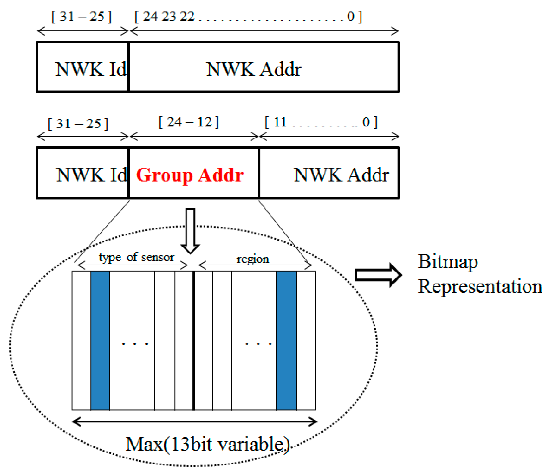
In order to address the downlink limitation of LoRa standard, cooperative downlink listening (CDL) is proposed. First, we modify the DevAddr used in the standard, as shown in Figure 6. During the ‘join’ process, DevEUI is used but the network server assigns a logical network address (DevAddr) and after the join procedure, all communications are based on the assigned DevAddr.
As shown in Figure 6, the standard DevAddr is divided into NwkId field and NwkAddr field. Without changes in the NwkId field, we partition the NwkAddr field into Group Addr field and NwkAddr field. It is important to note that unlike the other id field, the Group Addr field is represented not by a numeric number but by a bitmap. The Group Addr field is variable from 8 to 13 bits and the rule is defined by network server. The Group Addr field can also be divided into Type of Sensors (TOS) field and Region field. TOS is used to define the type of sensors equipped in an end device. For instance, Temperature, Humidity, Infrared, Light sensors can be represented respectively as follows: ‘1000’, ‘0100’, ‘0010’, ‘0001’. Representation of multiple sensors is also available. The bitmap ‘1100’ means temperature and humidity sensors. In addition, since LoRa can have long coverage, a single LoRa BS or LoRa Gateway can cover more than a few kilometers. Therefore, the divided subareas can be represented in the region field in the Group Addr. For example, as shown in Figure 6, the area which is covered by a single gateway is divided into four subareas such as A, B, C, and D. So, the information of subareas can be represented as follows: ‘1000’, ‘0100’, ‘0010’, and‘0001’. Based on the type of sensors and regional information, Group Addr is determined and then NwkAddr is arbitrarily assigned by network server.
Compared with DevAddr address system, since the NwkAddr field is reduced by adding the Group Addr field, the address space to be assigned in CDL is smaller than those of standard. That is, the address space is calculated by
where Nn is NwkId size, Nt is sensor type size, and Nr is region size.
Let us suppose that a device transmits its sensed data to the network server once an hour. Then, each node needs at least three seconds’ slot duration (including uplink, ACK, and downlink data slots), and thus only 3600 s/3 s = 1200 nodes can be covered by a single gateway in the area. So, the maximum number of address space of CDL is 4096 and the space is sufficient for a single gateway.
3.3. Basic Algorithm of CDL
LoRa end device can send data uplink to the gateway using various channels as shown in Table 1. In addition, as shown in Figure 4, RX1 and RX2 windows followed by uplink data transmission are used for downlink. In general, the RX1 window is used for ACK frame with respect to uplink transmission, and the channel and data rate of RX1 are the same as those used in uplink transmission. Unlike the RX1 window, the RX2 window can use different channel and data rate regardless of uplink transmission. Here, the key ideas of CDL are to utilize the new DevAddr system in which types of sensors and regional information are represented, and to enable broadcasting using the RX2 window. To achieve this, network server determines a fixed channel out of channels available in BS or Gateway, to be used for the RX2 window, and sends broadcast message using the RX2 window. We also define DownLink (DL) Initiator, which is responsible that all the nodes in the network wake up and listen to broadcast message of network server via gateway at its RX2 window by transmitting a downlink request to the network server periodically.
The network manager configures the Group Addr field with the area information and type of sensors. This can be preconfigured in factory or configured in the field using a specific device, such as installer, which can configure each device by establishing a connection to an end device using UART or wirelessly. After installation and deployment, each device starts the join process by sending ‘join’ request message to a nearby BS (or Gateway) based on DevEUI, AppEUI, AppKey. RFU bit in the ‘join’ request frame is set to ‘001’, which is to be notified of the CDL device, and its Group Addr information is included in MAC Payload. The BS, which listens to the ‘join’ request frame of a device, forwards it to network server, and the network server accepts the device to join its network. At that time, if the MType field is ‘000’ (join request) and RFU field is ‘001’ (CDL device) in the received MAC frame header, network server stores Group Addr information in the frame payload, and assigns DevAddr based on the Group Addr information received. A ‘join accept’ message is sent to the requestor, with DevAddr including the newly assigned NwkAddr (12 bits), NwkId, and Group Addr information.
After completion of the join process, irrespective of sensor type or its region, a DL initiator sends a downlink request message to the network server periodically. On the reception of downlink request message, the network server transmits a broadcast message using the RX2 window. The broadcast message of the network server may be time synchronization or instant query from the application server. Other devices wake up at every period and then listen to broadcast message of network server, more specifically BS, switching its channel to the RX2 channel. Here, downlink messages can be delivered to all the nodes or selective nodes through Group Addr information.
3.4. Network Time Synchronization
One of the key features of LoRaWAN is the low-power communication characteristic. In order to extend the lifetime of each end device that operates with battery, LoRa employed an uplink-oriented communication method. Therefore, each device transmits sensed data uplink to network server periodically based on its clock. It is well known that real time clock (RTC), used in IoT devices, might drift over time and thus it might cause various timing errors between device and network server. Therefore, one of the important issues in IoT applications is an efficient time synchronization service.
Due to its inherent downlink limitation, time synchronization of devices with the network server is not specified by LoRa specification. So, individual devices should be synchronized by receiving current time information of the network server. That is, when a device transmits its sensed data to the network server, time information from the network server can be achieved by being received at the following RX slots, as shown in Figure 5. However, this results in significantly increased additional network traffic, and it can also affect the communications of other devices.
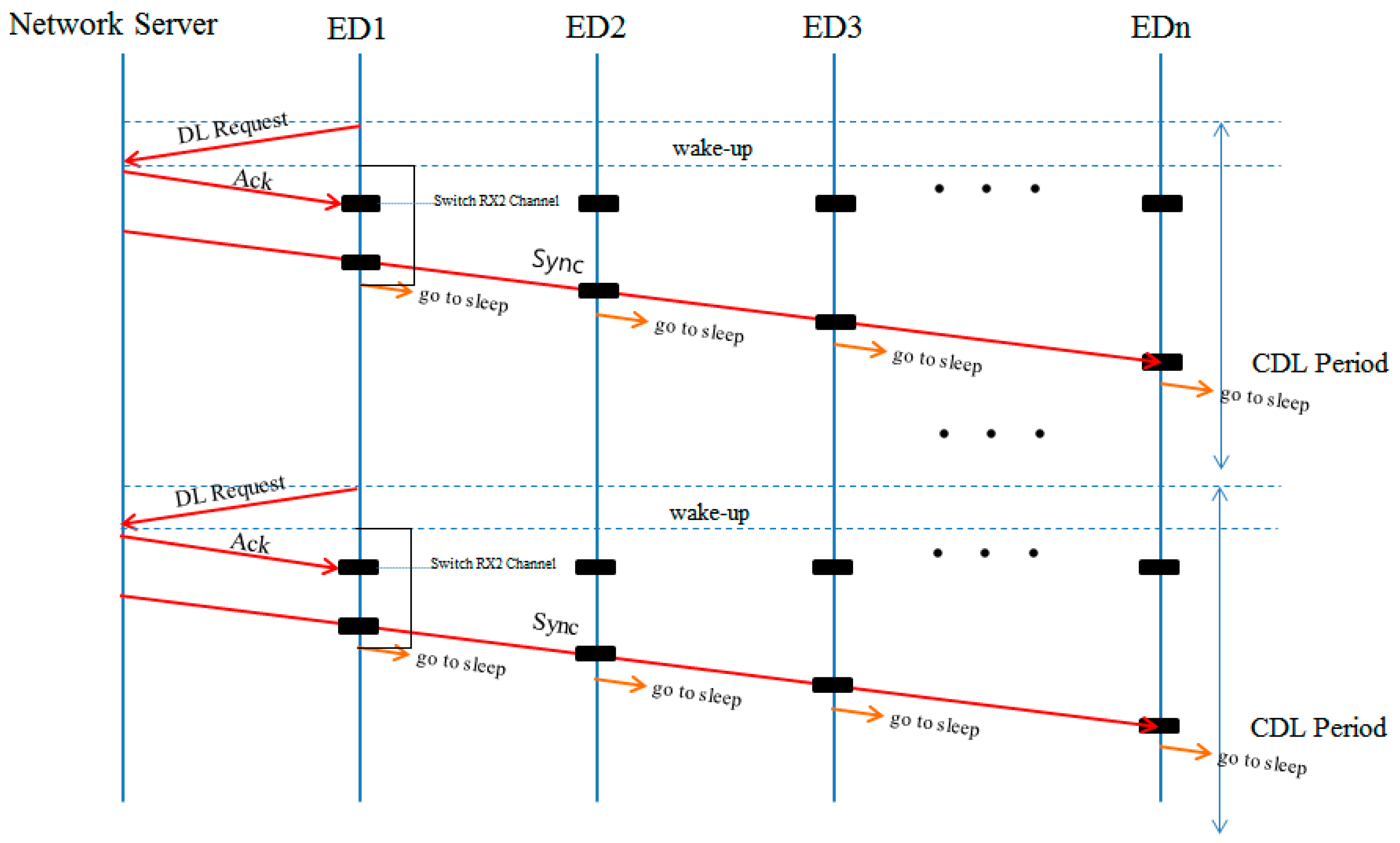
On the other hand, CDL enables devices to be synchronized concurrently with the network server utilizing broadcast RX window triggered by a DL initiator. As shown in Figure 7, in order to make the RX window broadcast, the DL initiator sends a DL request message to the network server periodically (generally, we consider every hour), and network server can use the broadcast RX window for broadcasting time information. Considering average clock drift, time synchronization may be performed at most once a day. The first RX window for downlink following DL request message is used for transmitting an ACK frame to the DL initiator, the network server captures the current time at the end of the first RX window, and then at the beginning of the second RX window, the captured time information is broadcasted. All the nodes in the network wake up at the beginning of the RX2 window and wait for the broadcast message from network server for the RX2 windows duration. On the reception of time synchronization message, nodes reconfigure their RTC to the time information received from the network server. It is important to note that unlike LoRa standard in which individual device should each be synchronized with a network sensor, since all nodes in CDL are capable of being synchronized by receiving time information of network server at the same time, traffic in the network is significantly reduced and thus the time difference between devices may be reduced.
3.5. Power Balancing
One of the outstanding features of CDL is that all nodes in the network utilize a common RX window for downlink periodically triggered by the DL initiator. However, this feature might also lead to more power consumption of the DL initiator than other normal listener nodes. Therefore, in order to avoid intensive power consumption of a specific node and balance power of all nodes in the network, the DL initiator is dynamically changed. DL initiator change is based on Fcnt (Frame Counter), which is managed by network server and each node. The Fcnt is also separated into FcntUp for uplink counter and FcntDown for downlink counter. Therefore, whenever a network server receives DL request message, it checks the following:
If the sum of two counter values is greater than or equivalent to the Threshold value, to elect a new DL initiator, the network server seeks a new DL candidate by the following:
where N is the set of nodes in the network.
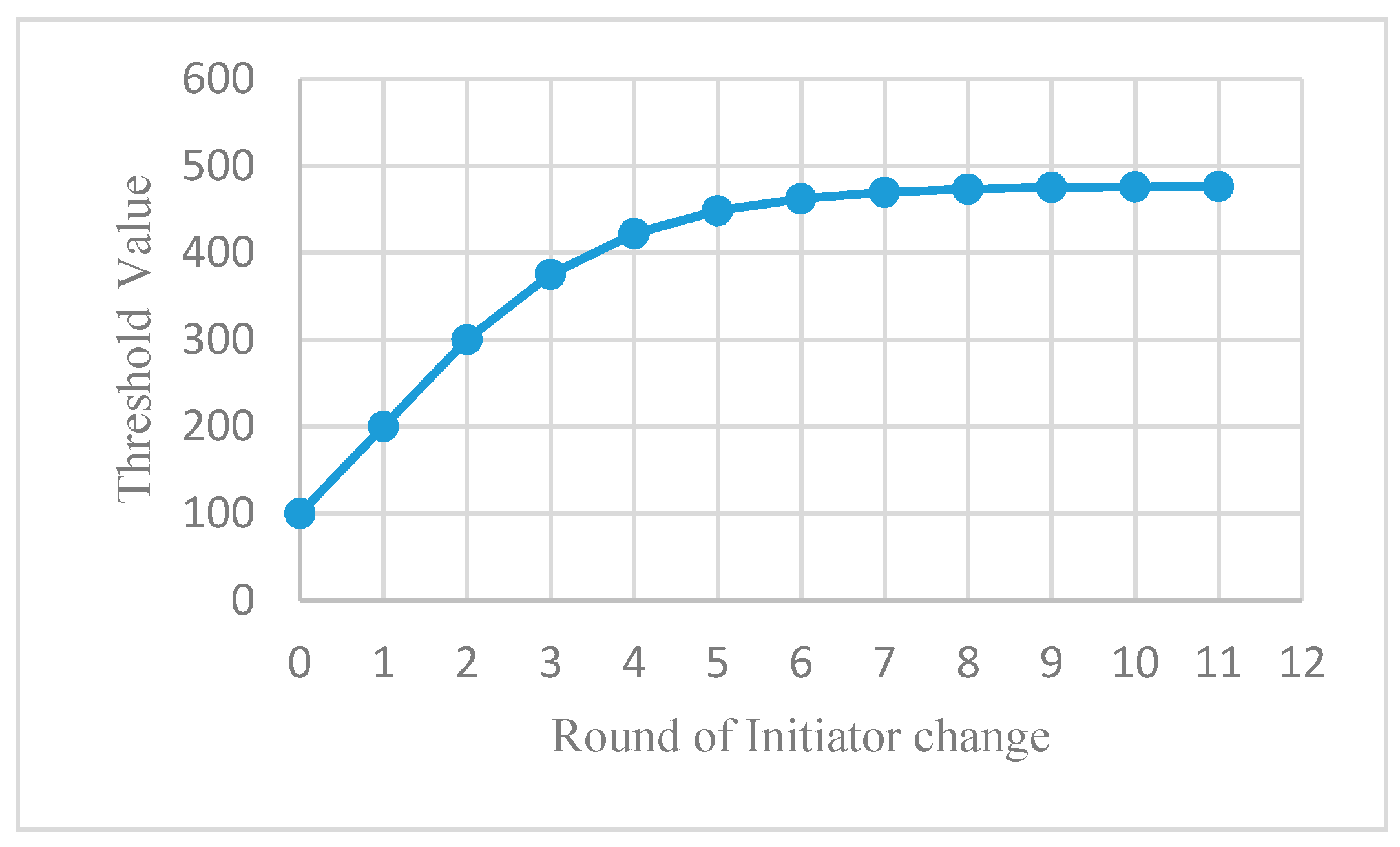
Here, the problem is what the best threshold value is. In case of taking a too small value, if the Fcnt value of all nodes in the network is greater than threshold, a new DL initiator cannot be elected. On the other hand, in case of taking too big of a threshold value, energy of original DL initiator can only be consumed intensively. Therefore, to resolve this problem, CDL changes the threshold value dynamically as follows:
This results in log scale variation of threshold value as shown in Figure 8. That is, it starts with small value but threshold value is maintained with a similar value when reaching almost maximum value. This makes it possible to continuously find a candidate node, which consumed the least energy, and enables the node to become a new DL initiator. Threshold value change is also performed together with a DL initiator change event. Therefore, since CDL dynamically elects a DL initiator node considering the Fcnt value of all nodes in the network, the power imbalance problem occurring due to periodic DL request message transmission can be resolved.
4. IoT Query Dissemination Based on CDL
CDL is capable of enabling not only downlink broadcasting by sharing cooperatively a downlink slot among devices, but also data-centric communication utilizing group address field efficiently. In this section, we introduce groupcasting and geocasting in association with CDL.
4.1. DL Groupcasting
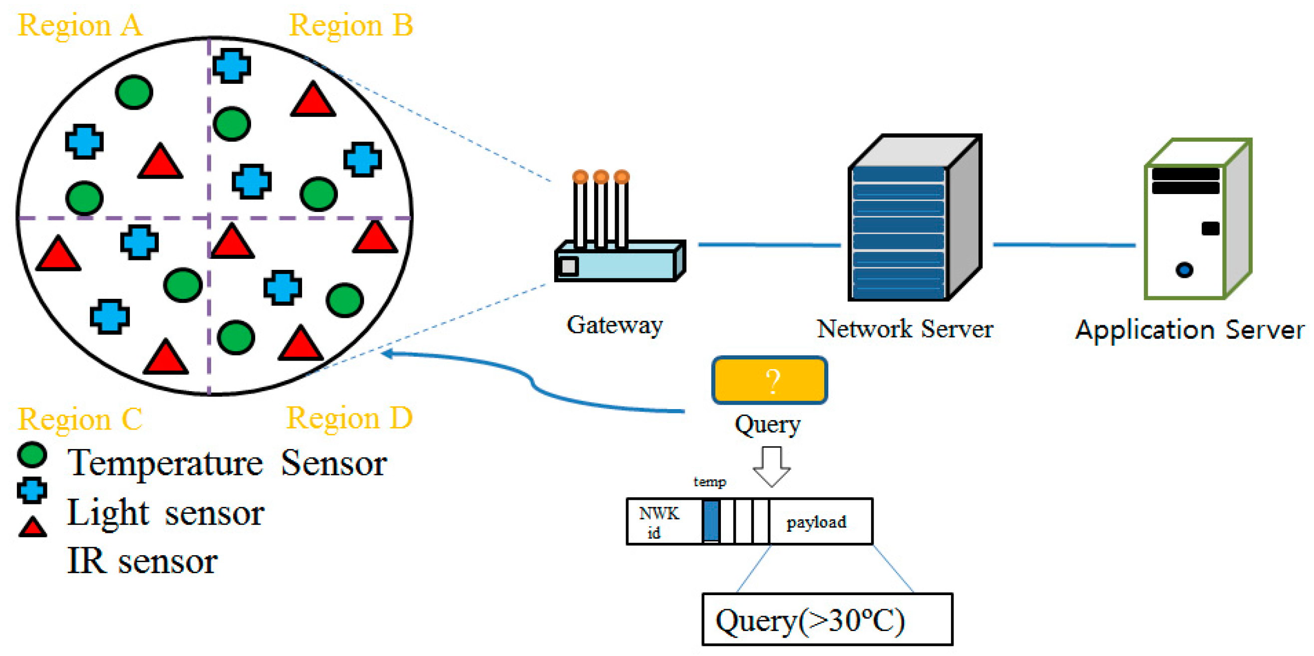
Groupcasting, which is a kind of multicasting, is used when data is requested only from the specific types of sensors in the network. For instance, as shown in Figure 9, the application server wants to know the sensors for which the temperature is higher than 30 degrees. In this case, the application server can request a query to the network server and it broadcasts to the nodes the message containing the Addr field, in which the temperature sensor bit is set, and the query as shown in Figure 9. As a result of the query, only the sensors which satisfy the condition (>30 °C) respond to the network server. The network server aggregates data and then the aggregated results might be sent to the application server. This groupcasting capability can reduce entire network traffic as well as excessive data storage in the network server.
4.2. CDL Geocasting
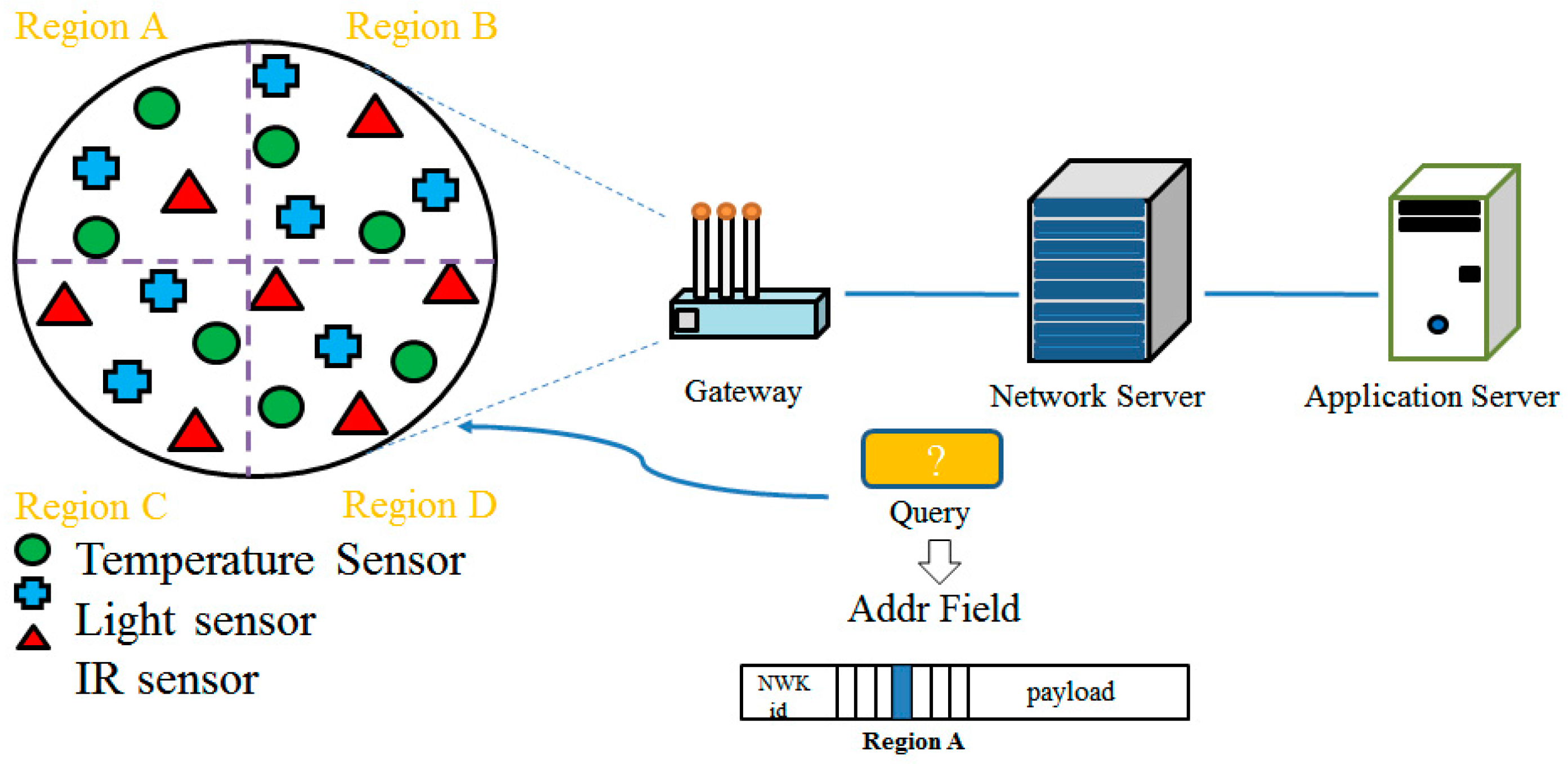
The Group Addr field already includes functionality capable of configuring a region field as well as sensor type field. Using the region field, the network server can receive data only from the sensors which are in a specific area without assistance of GPS. In particular, since the LoRa can cover more than a few kilometers in radius, it is necessary to divide into subareas the area which is covered by a single gateway. For instance, as shown in Figure 10, if a sensor field can be divided into four subareas (A, B, C, and D), CDL enables gathering sensor data only from sensors which are in a specific area. In this case, a user (application server) requests the recent data in the particular area, then the network server sets the corresponding bitmap in the region field and broadcasts the message into the network. Only the nodes in the interest area (e.g., area A) can respond to the network server. In addition, since the region field is expressed by bitmap, data gathering from multiple areas is also possible. For example, if the region field contains ‘0101’, it means both regions B and D. In addition, more advanced data-centric aggregation is available by utilizing a combination of sensor type field and region field. For example, the query can be as follows: only the nodes of which temperature is below 0 °C in the area A and D.
5. Performance Evaluations
In this section, we test each function of CDL, and conduct performance comparison with LoRa standard. While using basic functions of standard as it is, CDL is implemented by adding additional functionalities at the high level, so that data success ratio and delay analysis are skipped in this performance evaluation. As a result of our experiments, it is shown that the two metrics have almost similar performance to those of the standard, so that they are not arguable in this paper. Instead, we evaluate entire network traffic compared with LoRa standard, and energy consumption, which is the most important feature of LoRa, is analyzed.
5.1. Experimental Environment
In order to implement a LoRa network, we used off-the-shelf LoRa products [18]: Multitech mDot for end device and Conduit for LoRa gateway. Both end device and gateway are configured with Korean frequency regulation specified in the LoRa specification ver. 1.02, and 1 gateway and 5 end devices were used in our experiments. Since mDot and Conduit contains the LoRa standard stack, LoRa standard performance is tested based on the original systems, and on the top of LoRa standard, CDL is implemented. Our experiments are conducted on 5 end devices but based on the results from the real experiments we evaluated the performance in extensive environments as shown in Table 2.
5.2. Traffic Analysis
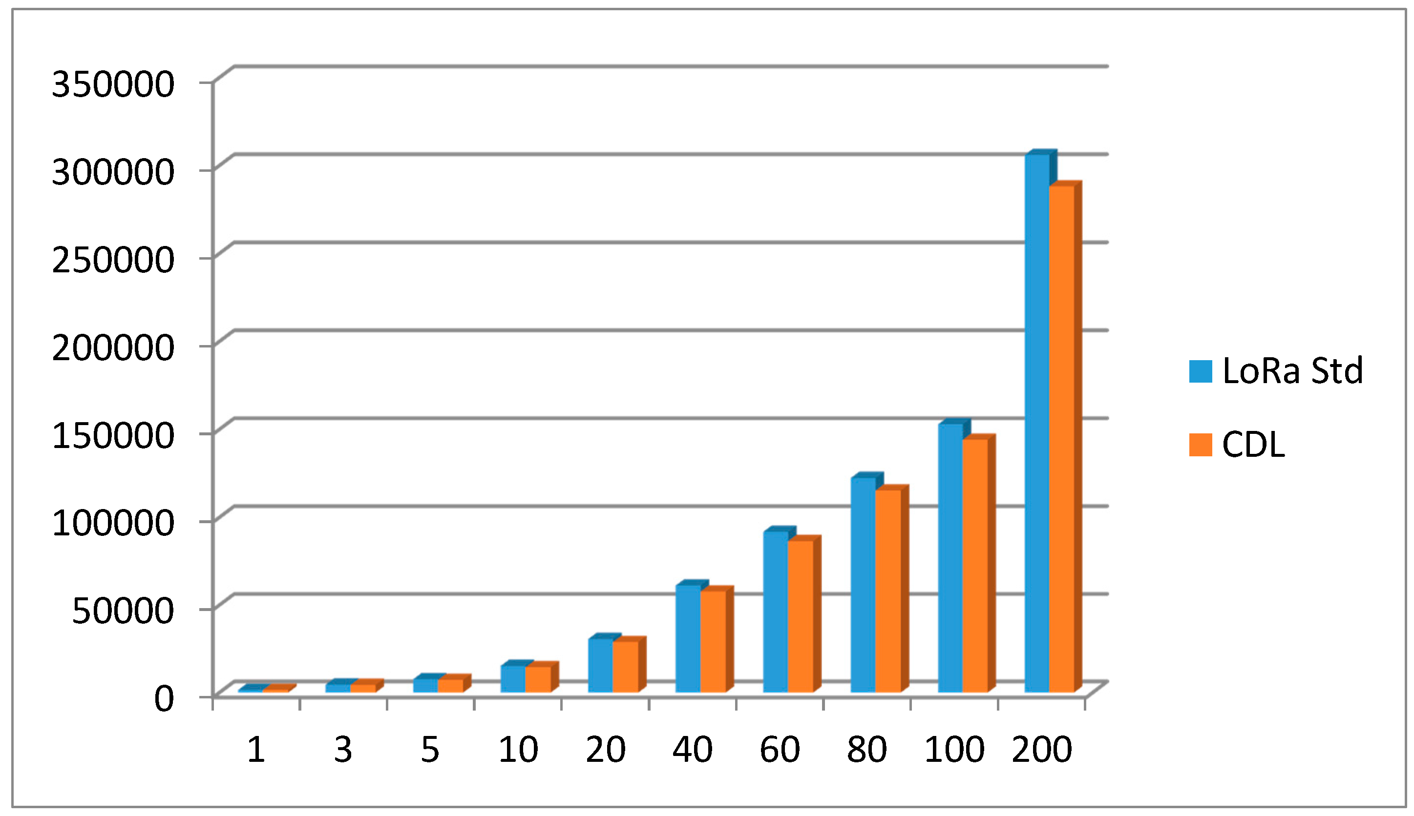
One of the critical features of the CDL is that by using a shared downlink slot, the network server is able to process broadcast messages transmitted to each ED. In particular, the time synchronization message of this broadcast message must be used periodically to synchronize all the nodes. Thus, in this experiment, each node is synchronized from the network server once a day, and the total amount of packets (i.e., traffic) generated in the network is measured when the network is maintained for 30 days. For more extended experiments, we measured the number of packets generated by increasing the number of nodes from 1 to 5, and based on this data, we calculated the number of packets when the number of nodes was increased from 10 to 100. In addition to the synchronization message once a day, each node sends its sensing data to the network server once an hour and uses a model that receives ACK for it. Figure 11 shows the total number of packets generated during a month in LoRa and CDL. The results show that when the number of nodes is small, the amount of traffic of LoRa standard and CDL does not show much influence on broadcasting, so there is no great difference in the total amount of traffic, but the amount of traffic is remarkable as the number of nodes increases. This is because the CDL broadcast function has been effective in reducing the traffic. In particular, in LoRa, a large number of nodes are accommodated in a single gateway due to a long communication distance. However, the larger the network, the more the traffic reduction effect becomes.
5.3. Energy Consumption and Battery Lifetime
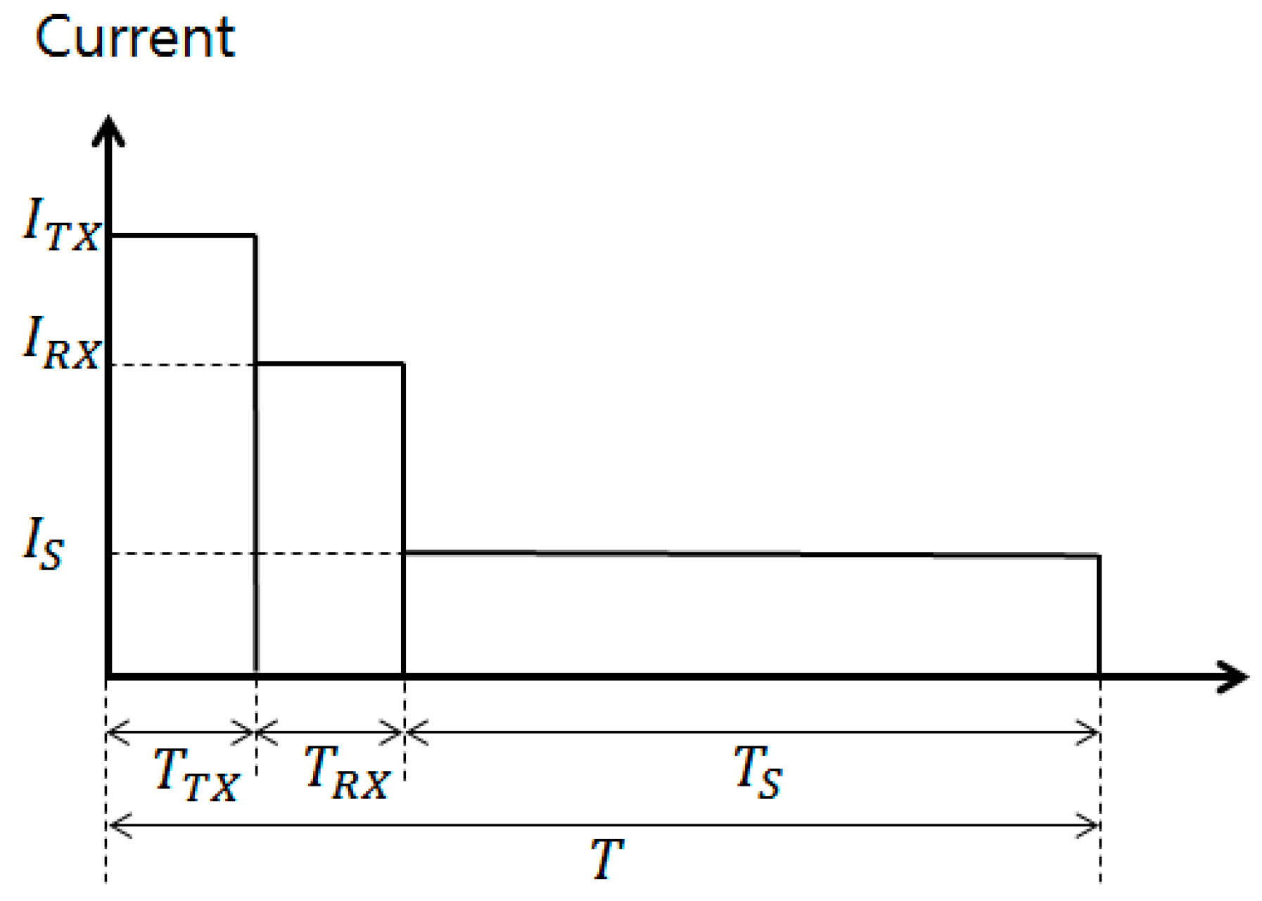
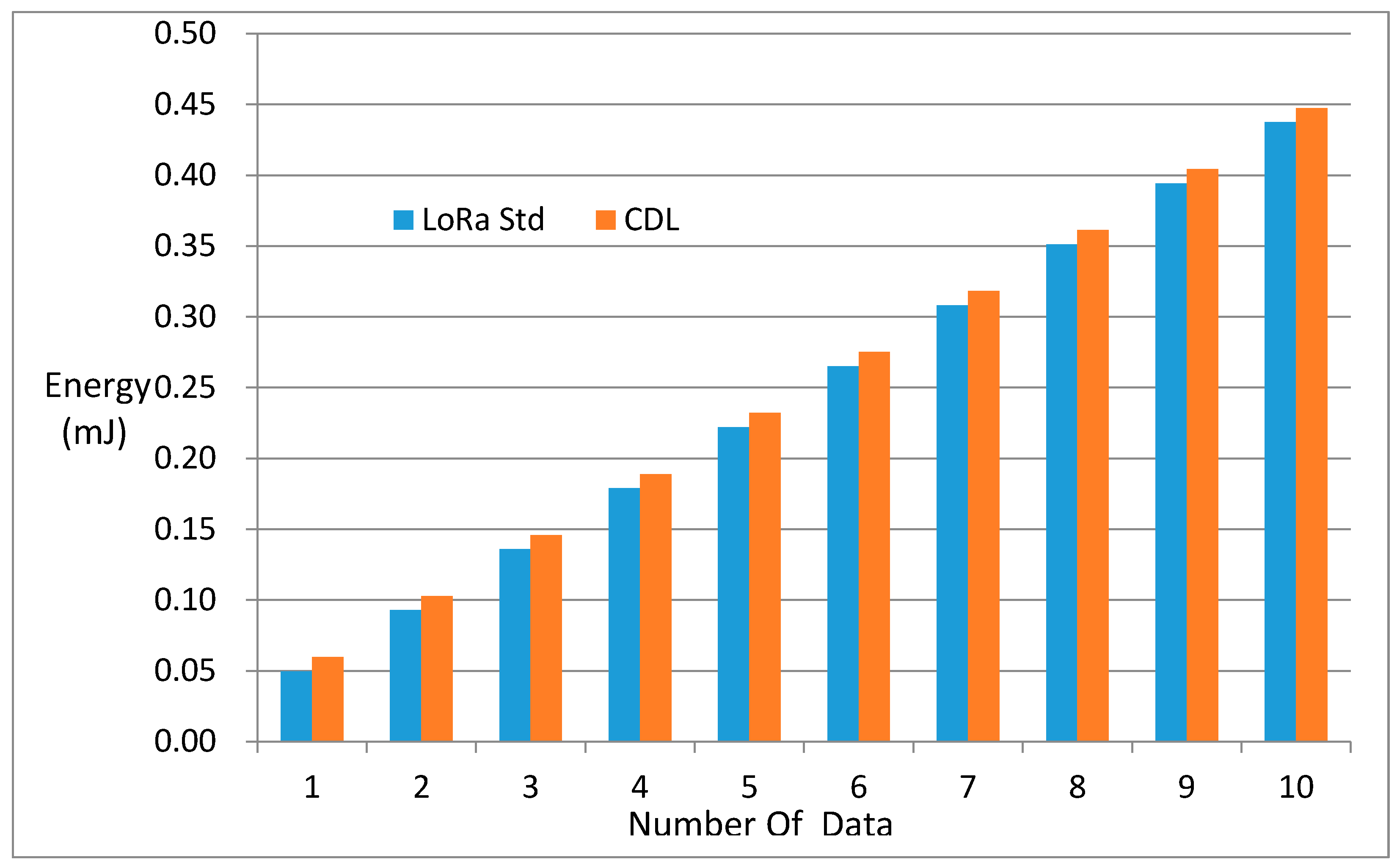
One of the most important features of LoRa is its low-power communication capability. This low-power capability is very attractive for a variety of IOT applications. This experiment evaluates energy consumption of LoRa standard and CDL. LoRa gateways are not considered because they are supplied with AC power. The current consumption at each state is shown in Table 2. (They include MCU current consumption). As shown in Figure 12, to measure the power consumption, we divide into the following three states (TX state, RX state, SLEEP state), integrate the consumption current according to each state into each state time, The power consumption was calculated by multiplying the power consumption by the power consumed during one hour. Figure 13 shows the results of increasing the number of data transfers per node from 1 to 10 for one cycle (1 h). In fact, CDL is an extended version of the standard LoRa, yet it accommodates all of the low-power features in LoRa, so the energy consumption of each node is not significantly different. This does not take into account the effects of broadcasts, and if time synchronization is taken into consideration, energy consumption may be slightly less than that of the standard LoRa.
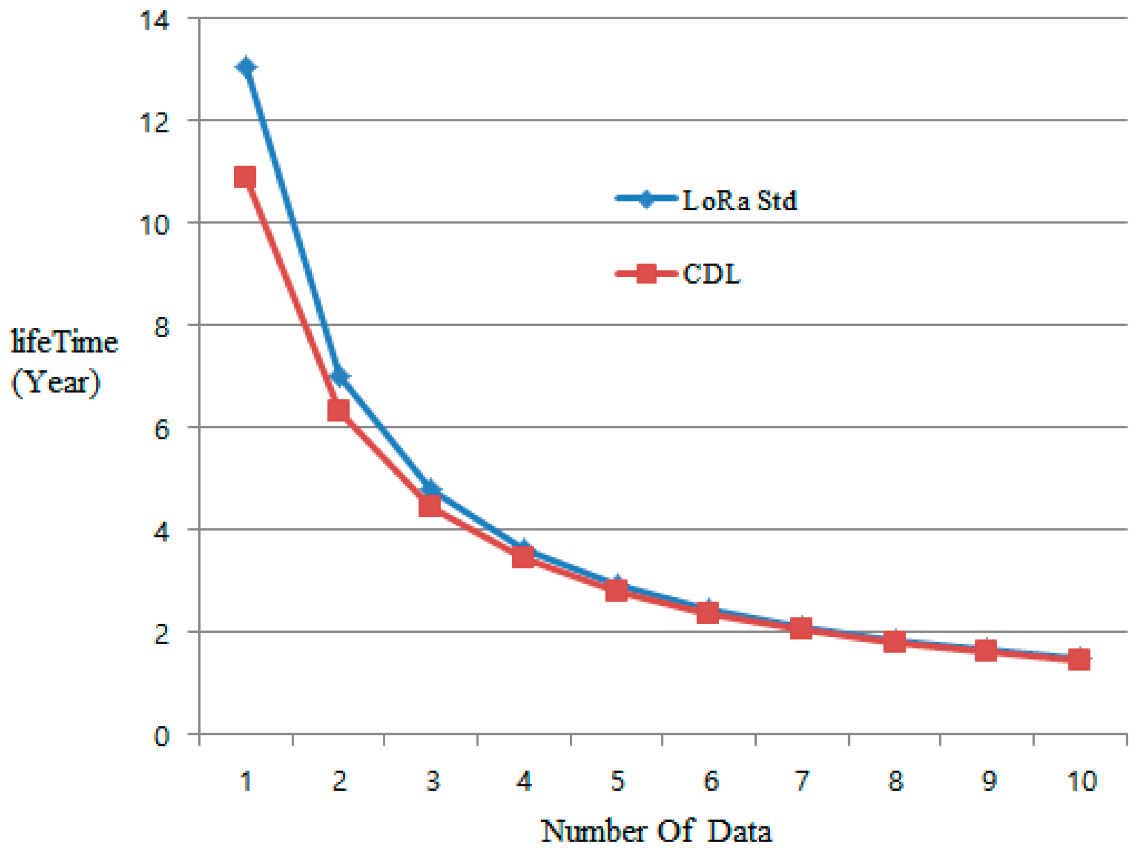
To further understand the more intuitive energy consumption, we also calculated the battery life of a node based on two AA batteries. Figure 14 shows the battery life when transferring data from 1 to 10 times per hour. As shown in the figure, when the data is sent once or twice in one hour, the CDL tends to be somewhat shorter than the standard LoRa due to the additional energy consumption for maintaining the shared downlink slot. However, as the number of data increases, it converges to the consumed amount. Also, considering the data transmission once per hour, CDL can guarantee a lifetime of more than 10 years as well as LoRa, which is also suitable for long life applications such as remote meter reading.
6. Conclusions
In this paper, we have dealt with LoRaWAN, a representative technology of LPWAN. In particular, we addressed a fundamental problem in LoRaWAN, the DOWNLINK constraint, by cooperative downlink listening, which is based on a shared downlink slot triggered periodically by the DL initiator. In addition, energy balancing has been achieved through the selection of a dynamic DL initiator to avoid intensive energy consumption of the DL initiator. In addition, it shows that various data-centric models, groupcasting and geocasting, are possible in association with CDL. The CDL was implemented with minimal modifications to the existing LoRa standard and maintained compatibility with the LoRa standard. Experiments have shown that the CDL significantly reduces traffic over the LoRa standard, especially when the number of nodes in a network increases significantly. In addition, CDL showed almost similar energy consumption compared to LoRa, and it was shown that it can guarantee battery life of more than 10 years considering one hour communication. Based on the results of this paper, it is expected that it can be applied to various application fields based on LoRaWAN.
Acknowledgments
This research was supported by Basic Science Research Program through the National Research Foundation of Korea (NRF) funded by the Ministry of Education (Grant No. 2015R1D1A1A01059317).
Author Contributions
The authors listed all contributed to the development of the idea and experiments contained within this paper. More specifically, the first version of this paper was written by the corresponding author, Kwang-il Hwang, and structure and revisions of this paper were led by the 1st author.
Conflicts of Interest
The authors declare no conflict of interest.
References
- LoRa Alliance, Inc. LoRaWAN™ Specification; LoRa Alliance, Inc.: San Ramon, CA, USA, 2015. [Google Scholar]
- LTE-M Optimizing LTE for the Internet of Things. White Paper. Available online: https://novotech.com/docs/default-source/default-document-library/lte-m-optimizing-lte-for-the-internet-of-things.pdf?sfvrsn=0 (accessed on 3 February 2016).
- Cellular System Support for Ultra-Low Complexity and Low Throughput Internet of Things. Available online: https://portal.3gpp.org/desktopmodules/Specifications/SpecificationDetails.aspx?specificationId=2719 (accessed on 16 August 2016).
- Sigfox Homepage. Available online: http://www.sigfox.com (accessed on 13 January 2016).
- Fernández-Garcia, R.; Gil, I. An alternative wearable tracking system based on a low-power wide-area network. Sensors 2017, 17, 592. [Google Scholar] [CrossRef] [PubMed]
- Trasviña-Moreno, C.A.; Blasco, R.; Marco, Á.; Casas, R.; Trasviña-Castro, A. Unmanned aerial vehicle based wireless sensor network for marine-coastal environment monitoring. Sensors 2017, 17, 460. [Google Scholar] [CrossRef] [PubMed]
- Aquino-Santos, R.; González-Potes, A.; Edwards-Block, A.; Virgen-Ortiz, R.A. Developing a new wireless sensor network platform and its application in precision agriculture. Sensors 2011, 11, 1192–1211. [Google Scholar] [CrossRef] [PubMed]
- Adelantado, F.; Vilajosana, X.; Tuset-Peiro, P.; Martinez, B.; Melia, J. Understanding the limits of LoRaWAN. Available online: https://arxiv.org/pdf/1607.08011.pdf (accessed on 27 July 2016).
- Mikhaylov, K.; Petäjäjärvi, J.; Haenninen, T. Analysis of capacity and scalability of the LoRa low power wide area network technology. In Proceedings of the European Wireless 2016, 22th European Wireless Conference, Oulu, Finland, 18–20 May 2016; pp. 119–125. [Google Scholar]
- Kim, D.Y.; Jung, M. Data transmission and network architecture in long range low power sensor networks for iot. Wirel. Pers. Commun. 2017. [Google Scholar] [CrossRef]
- Taneja, M. 802.11 ah-LPWA interworking. In Proceedings of the 2016 IEEE NetSoft Conference and Workshops (NetSoft), Seoul, Korea, 6–10 June 2016. [Google Scholar]
- Schroder Filho, H.G.; Pissolato Filho, J.; Moreli., V.L. The adequacy of LoRaWAN on smart grids: A comparison with RF mesh technology. Proceeding of the 2016 IEEE International Smart Cities Conference (ISC2), Trento, Italy, 12–15 September 2016. [Google Scholar]
- Toussaint, J.; EI Rachkidy, N.; Guitton, A. Performance analysis of the on-the-air activation in LoRaWAN. Proceeding of the 2016 IEEE 7th Annual Information Technology, Electronics and Mobile Communication Conference (IEMCON), Vancouver, BC, Canada, 13–15 October 2016. [Google Scholar]
- Petäjäjärvi, J.; Mikhaylov, K.; Hämäläinen, M.; Iinatti, J. Evaluation of LoRa LPWAN technology for remote health and wellbeing monitoring. Proceeding of the 10th International Symposium on Medical Information and Communication Technology (ISMICT), Worcester, MA, USA, 20–23 March 2016. [Google Scholar]
- Petäjäjärvi, J.; Mikhaylov, K.; Roivainen, A.; Hanninen, T.; Pettissalo, M. On the coverage of LPWANs: Range evaluation and channel attenuation model for LoRa technology. Proceeding of the 2015 14th International Conference on ITS, Copenhagen, Denmark, 2–4 December 2015. [Google Scholar]
- Pham, C. Building Low-Cost Gateways and Devices for Open LoRa IoT Test-Beds. In Testbeds and Research Infrastructures for the Development of Networks and Communities, Proceeding of the 11th International Conference TRIDENTCOM, Hangzhou, China, 14–15 June 2016; Springer: Cham, Switzerland, 2016; pp. 70–80. [Google Scholar]
- LoRa Alliance. A Technical Overview of LoRa and LoRaWAN. White Paper. Available online: https://www.lora-alliance.org/portals/0/documents/whitepapers/LoRaWAN101.pdf (accessed on 1 November 2015).
- Multitech Product. Available online: https://www.multitech.net (accessed on 1 January 2017).
Figure 1.
Long-range (LoRa) regional spectrum usage (Adapted from the specification Ver.1.02 regional Parameters, LoRa Alliance, 2016).
Figure 1.
Long-range (LoRa) regional spectrum usage (Adapted from the specification Ver.1.02 regional Parameters, LoRa Alliance, 2016).

Figure 2.
Long-range wide-area network (LoRaWAN) architecture (Adapted from LoRa Whitepaper, LoRa Alliance, 2015 [16]).
Figure 2.
Long-range wide-area network (LoRaWAN) architecture (Adapted from LoRa Whitepaper, LoRa Alliance, 2015 [16]).

Figure 3.
LoRa protocols stack (Adapted from LoRa Specification Ver.1.02, LoRa Alliance, 2016).

Figure 4.
Class A end device slot timing (Adapted from LoRa Specification Ver.1.02, LoRa Alliance, 2016).
Figure 4.
Class A end device slot timing (Adapted from LoRa Specification Ver.1.02, LoRa Alliance, 2016).

Figure 5.
Device time synchronization in LoRa standard.

Figure 6.
DevAddr block partition.

Figure 7.
Cooperative downlink listening (CDL) time synchronization.

Figure 8.
Threshold variation.

Figure 9.
Groupcasting based on CDL.

Figure 10.
Geocasting based on CDL.

Figure 11.
Network traffic observation.

Figure 12.
Power state in terms of communications.

Figure 13.
Energy consumption.

Figure 14.
Battery life.


Table 1.
LoRa frequency usage (in Korea ISM band).
| Channel Index | Frequency (MHz) | Power Index | Tx Power Value (dBm) | Description | |
|---|---|---|---|---|---|
| 1 | 922.1 | 0 | 14 | Default channel | RX1 channel |
| 2 | 922.3 | 0 | 14 | ||
| 3 | 922.5 | 0 | 14 | ||
| 4 | 921.9 | 4 | 10 | RX2 channel | |
| 5 | 922.7 | 0 | 14 | ||
| 6 | 922.9 | 0 | 14 | ||
| 7 | 923.1 | 0 | 14 | ||
| 8 | 923.3 | 0 | 14 | ||
Table 2.
Experimental environments.
| Parameter | Value |
|---|---|
| Current on Tx | 36 mA |
| Current on Rx | 11 mA |
| Current on sleep | 2 uA |
| RX1 window duration | 1 s |
| RX2 window duration | 1 s |
| TX duration | 1 s |
| Supply Voltage | 3.3 V |
| CDL period | 1 h |
© 2017 by the authors. Licensee MDPI, Basel, Switzerland. This article is an open access article distributed under the terms and conditions of the Creative Commons Attribution (CC BY) license (http://creativecommons.org/licenses/by/4.0/).
Share and Cite
MDPI and ACS Style
Kim, B.; Hwang, K.-i. Cooperative Downlink Listening for Low-Power Long-Range Wide-Area Network. Sustainability 2017, 9, 627. https://doi.org/10.3390/su9040627
AMA Style
Kim B, Hwang K-i. Cooperative Downlink Listening for Low-Power Long-Range Wide-Area Network. Sustainability. 2017; 9(4):627. https://doi.org/10.3390/su9040627
Chicago/Turabian StyleKim, Byoungwook, and Kwang-il Hwang. 2017. "Cooperative Downlink Listening for Low-Power Long-Range Wide-Area Network" Sustainability 9, no. 4: 627. https://doi.org/10.3390/su9040627
Note that from the first issue of 2016, this journal uses article numbers instead of page numbers. See further details here.