Validation of Sensing Ocean Surface Currents Using Multi-Frequency HF Radar Based on a Circular Receiving Array


1
School of Electronic Information, Wuhan University, Wuhan 430072, China
2
Collaborative Innovation Center for Geospatial Technology, Wuhan University, Wuhan 430072, China
3
National Center of Ocean Standard and Metrology, Tianjin 300112, China
*
Author to whom correspondence should be addressed.
Remote Sens. 2018, 10(2), 184; https://doi.org/10.3390/rs10020184
Submission received: 29 November 2017
/
Revised: 20 January 2018
/
Accepted: 23 January 2018
/
Published: 26 January 2018
(This article belongs to the Special Issue Ocean Surface Currents: Progress in Remote Sensing and Validation)
Abstract
:To reduce the floor space of receiving antenna arrays, the Radio Ocean Remote SEnsing (RORSE) laboratory of Wuhan University developed a circular receiving array for a multi-frequency high frequency (MHF) radar system in 2014, consisting of seven uniformly spaced antenna elements positioned on a circle with a diameter of 5 m. The new system, which is abbreviated MHF-C radar, adopts frequency modulated interrupted continuous wave (FMICW) chirps and is capable of simultaneously operating at a maximum of four frequencies in the band of 7.5–25 MHz, and providing current, wave and wind maps every ten minutes. The phase direction-finding method is utilized to estimate the directions of the current signals, and array phase uncertainties are also taken into consideration in the signal model. This paper introduces the system in detail and investigates the performance of current measurements using MHF-C radars installed at Shengshan and Zhujiajian along the coast of the East China Sea. Radial current measurements derived from 8.27 MHz and 19.20 MHz at the same range are compared. Observations and comparisons between MHF-C radars and acoustic Doppler current profilers (ADCPs) are also presented in this paper. The results preliminarily demonstrate that the MHF-C radar system is capable of maintaining the same performance for current measurements whenever it steers to any other azimuth in the coverage and has a good ability to measure currents.

1. Introduction
With the theoretical and technological developments over the past several decades [1], coastal high frequency (HF) radar has achieved widespread acceptance for sensing ocean surface currents. Many countries have reportedly built HF radar systems with the ability to provide currents from close to the coast to more than 200 km offshore [2,3,4,5,6]. The two most representative HF radar systems, SeaSonde and WEllen RAdar (WERA), have already been used for various oceanic applications, such as coastal current observation, oil spill prediction, and maritime security, in different countries all around the world [7,8,9,10].
The majority of HF radar systems in operation around the world generally operate at a fixed frequency. HF radars, operating at more than one frequency, have the advantage of simultaneously providing current maps with different maximum ranges and various range resolutions. Previous studies indicated that the depth of HF radar-derived current depends on the frequency at which it operates by theory and very limited observations [11]. The potential application of multi-depth current data obtained by HF radar offers the option of exploring the coupling mechanism between winds and currents, and more information may be extracted from multi-frequency echoes. However, few studies have focused on HF radar with the ability to operate at multiple frequencies. Teague et al. showed current observations measured from 4.8 MHz to 21.8 MHz data by multi-frequency coastal radar (MCR) [12]. The Radio Ocean Remote SEnsing (RORSE) laboratory of Wuhan University designed and developed a multi-frequency HF (MHF) radar system with a planar receiving antenna array in 2007 [13]. To reduce the floor space of the receiving antenna array, we designed a seven-element circular receiving array that is uniformly located on a circle with a diameter of 5 m, and it was fully finished in 2014.
The accuracy of using HF radar to obtain radial current maps depends on numerous factors that may be divided into two aspects: estimating the velocity of current signals and estimating their direction of arrival (DOA). The velocity resolution of current measurements can be determined by the Doppler sampling period, radio wavelength and integration time. However, accurately determining the DOA of current signals and assessing the estimation performance are much more complex. Studies focused on current measurements with different HF radar systems have been previously performed by researchers all over the world in the past several decades, and a number of studies have evaluated the MUltiple SIgnal Characterization (MUSIC) algorithm or antenna pattern for direction-finding HF radar [14,15]. Many studies comparing HF radar current measurements with in situ current measurements have been developed by researchers interested in radar performance [16,17,18,19,20,21]. Other studies that compare HF radar-derived currents with drift buoy data were also conducted over the past several years [22,23,24,25,26]. More recently, studies have been performed to develop a method of calibrating the receiving antenna (array), and promising results have also been reported for direction-finding and beam-forming HF radar systems [27].
This paper introduces the newly designed MHF radar system based on a circular receiving antenna array (MHF-C radar). The performance of this system for current measurements is analyzed and validated by observations and comparisons. The paper is structured as follows. Section 2 shows the methods of obtaining current maps by MHF-C radar. Section 3 presents the experimental results of the MHF-C radar current measurements. Section 4 discusses the results. Section 5 provides the conclusions.
2. Methods
2.1. MHF-C Radar System
To enable monostatic operation, the MHF-C radar, which is capable of simultaneously operating at a maximum of four frequencies in the band from 7.5 MHz to 25 MHz, adopts frequency modulated interrupted continuous wave (FMICW) chirps for radio energy radiation. The waveform presents several differences from the traditional FMICW waveform, which has already been widely used in the field of HF radar oceanic remote sensing [7]. During one Doppler sampling period, the radar transmits a maximum of four FMICW chirps with different frequencies, bandwidths and sweep lengths in chronological order and then receives the backscattered signals modulated by sea surface movements at corresponding frequencies. The range spectra are obtained from sea surface echoes via a series of signal processing steps, such as frequency mixing, A/D sampling and fast Fourier transformation (FFT).
After coherent integration, four frequencies of Doppler spectra can be estimated by FFT after 512 or 1024 Doppler sampling periods. Then, every ten minutes, the MHF-C radar is able to simultaneously extract currents, waves and winds from the Doppler spectra of different frequencies. Preliminary results have already indicated that this mechanism has the ability to provide ocean surface current and wave maps with multiple operating frequencies for a number of parameters, such as radial currents, current vectors, significant wave heights and averaged wave periods [28,29,30].
The receiving array consists of seven uniformly spaced dipole antenna elements positioned on a circle with a diameter of 5 m, as shown in Figure 1. Each wide band antenna is designed for receiving signals from 7.5 MHz to 25 MHz with a height of 3 m and a standing-wave ratio (SWR) below 1.8. The transmitting part, which consists of three 7.5-m monopole antennas that occupy an area of m, is capable of radiating omnidirectional electromagnetic energy in the band of 7.5–25 MHz to the sea surface. The transmitting antennas were installed on a ground mat realized by alloy wires. The distance between the transmitting antennas and receiving antennas is approximately 100 m. Table 1 shows more details of the MHF-C system.
2.2. Radial Current Measurements
The corresponding Doppler frequency, , in the absence of surface currents is expressed as follows:
where represents the velocity of the Bragg waves, and it can be derived from the deep water gravity wave dispersion relation for grazing incidence:
where is the radar wavelength and g is the acceleration caused by gravity.
When currents are present, the frequency offsets from this first-order Bragg peak () are proportional to the radial current for a wave advancing (positive) or receding (negative) from the radar station:
where is the radial component of the current along the direction of the radar. HF radar radial current measurements consist of determining (first-order peak offsets from its theoretical value) and (angle of arrival with respect to the surface current signal). can be easily estimated, and its performance mainly depends on the power spectrum frequency resolution and radio wavelength. However, the method of estimating requires more improvements, and it has been the subject of considerable research in recent years.
2.3. Signal Model and Estimation Method
The MHF-C radar system adopts a direction-finding approach (MUSIC algorithm) rather than the beam-forming technique to estimate the direction of the current signal arrival. The MUSIC algorithm estimates the DOA of current signals by taking advantage of the phase differences that occur from an ocean surface cell to antenna elements. This algorithm takes Doppler power spectra input from all antenna elements at a specific first-order frequency bin (current velocity) away from the non-current Bragg frequency (defined by Equation (1)) and inverts this input to a spatial spectrum from which we can obtain the direction of the current signal arrival. Theoretically, the number of directions that can be resolved from a single radial current shift is limited to six for this seven-element array.
Considering M disparate sources received in N non-linear array elements, a conventional data model for each source can be written as follows:
where is the observation vector corresponding to the ith source; denotes the steering vector of the bearing ; is the wavenumber relative to the operating frequency; signifies the nth sensor position in rectangular coordinates; is defined as the gain matrix; and represents the phase error matrix. We take the first sensor as the reference sensor defining ; is the received signal; and designates the additive noise vector.
For the ith independent signal, the covariance matrix of the signal is estimated as follows:
The MUSIC algorithm is applied to estimate the N signal directions-of-arrival:
where represents the noise subspace derived from the eigen-decomposition of the covariance matrix of i th source. For a phased direction-finding HF radar system, array phase uncertainties significantly degrade the performance of estimating the azimuth of the current signal. In this paper, an auto-calibration method is utilized to estimate to calibrate the array signals before estimating the current maps [31,32]. As shown in Equation (6), the number of disparate sources M must be accurately estimated before using Equation (6) to determine the DOAs of current signals. In the MHF-C radar, seven eigenvalues satisfying are derived from the eigen-decomposition of the covariance matrix. The biggest gradient of the eigenvalues ( ) is calculated as the boundary between the signal subspace and noise subspace. Thus, the number of disparate sources is determined.
3. Results
Two MHF-C radar systems were installed at the Shengshan and Zhujiajian sites located along the coast of the East China Sea in 2014. Since then, these two MHF-C radars have functioned to provide current, wave and wind fields for the users. As shown in Table 2, four periods of observations are presented in the paper to demonstrate the performance of the MHF-C radar current measurements. Observation Period I and II of this paper were collected using the two radars from 11 March to 15 March 2016 and from 14 June to 30 June 2016, respectively. The MHF-C radar at the Shengshan site operated at 8.27 MHz (f1) and 19.20 MHz (f2), whereas the MHF-C radar at the Zhujiajian site operated at 7.88 MHz during Observation Period I and II. Observation Period III includes the radial current measurements that were obtained from the MHF-C radar at the Shengshan site operated at 8.27 MHz and acoustic Doppler current profilers (ADCPs) from 16 June to 12 August 2015. Observation Period IV includes the radial current measurements that were obtained from the MHF-C radars at the two sites and ADCPs in April 2015.
3.1. Spatial Coverage of Radial Currents
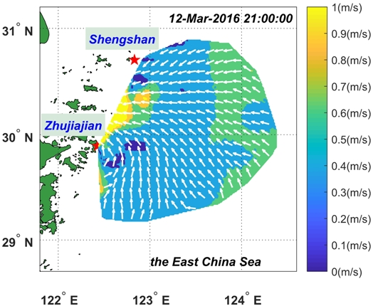
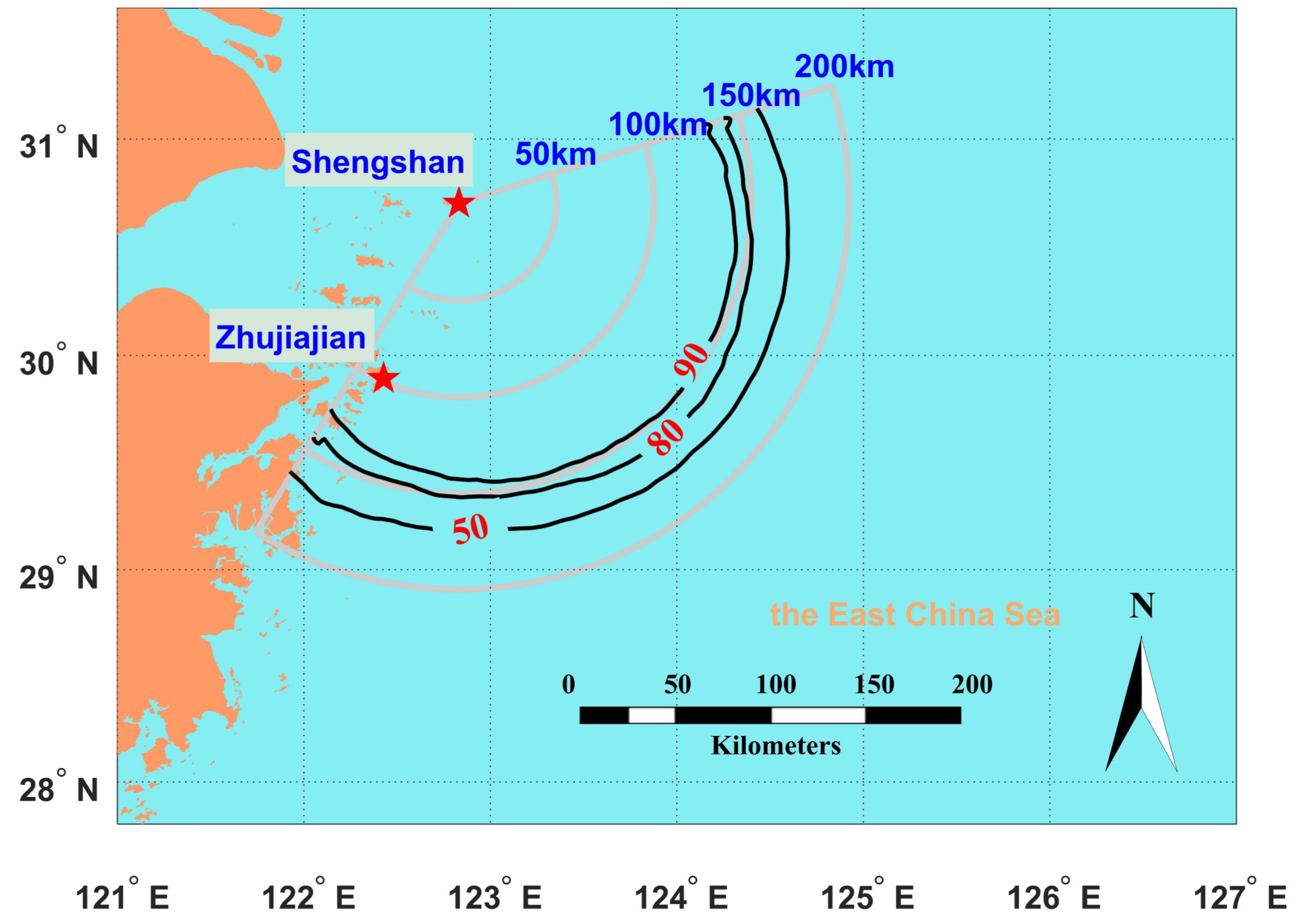
Analyzing the percent coverage map is a possible method of examining the actual spatial coverage of radar current measurements. For the MHF-C radar, the signal to noise ratio (SNR) threshold of the first-order signal, which is related to the spatial coverage and accuracy of current measurements, is set to 8 dB for the current estimation. Figure 2 shows the spatial coverage of radial currents estimated from the 8.27 MHz data that were obtained from the Shengshan radar from 11 March to 15 March 2016. The gray lines indicate the range of the Shengshan radar, and the black contour lines indicate the percent spatial coverage of current measurements. The percent coverage of currents at the range of 150 km is approximately 90%. As shown in Figure 3, from 11 March to 15 March 2016, the Zhujiajian radar operating at 7.88 MHz shows a similar detection distance with a percent coverage of 90% at the range of 150 km, and the 50% contour line reaches 190 km.
3.2. Comparisons between Two Operating Frequencies
Because the MHF-C radar is capable of radiating an ocean patch with diverse operating frequencies in every Doppler period, the constant current velocity in the patch can be extracted from different Doppler spectra obtained from the echoes at corresponding operating frequencies. During Observation Period I and II, the signals at 8.27 MHz (f1) were able to sense sea surface currents up to 200 km offshore with a range resolution of 5 km, and echoes operating at 19.20 MHz (f2) were used to provide near shore radial current maps with a range resolution of 1 km. Both operating frequencies (f1 and f2) are able to provide radial current measurements at the range of 25 km every ten minutes. Comparisons between f1-derived and f2-derived radial current series at the same sampling cell provide a direct approach to evaluate the consistency of current measurements.
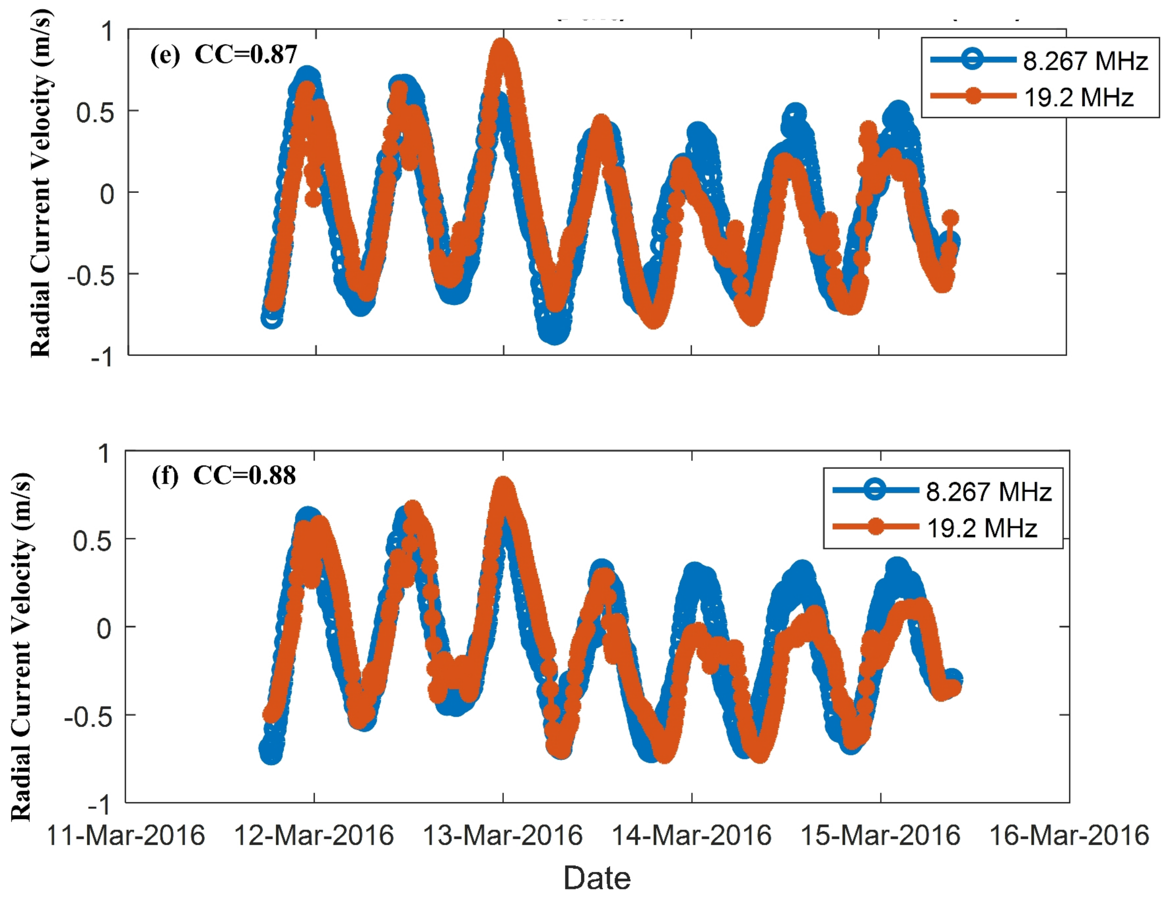
The blue line in Figure 4 shows that thirty sampling cells are in the range of 25 km by varying the azimuthal angle from −75 to 70 with a uniform interval of 5 . For Observation Period I, thirty comparisons are performed between the f1-derived and f2-derived radial current series at these cells, and several typical comparisons are shown in Figure 5. Figure 5a shows the comparison between f1-derived and f2-derived radial current series at the azimuthal angle of −75 . The f1-derived currents match well with the f1-derived time series with a correlation coefficient (CC) of 0.93. The time series at azimuthal cells of −45 , −30 , 0 , 15 and 45 are also shown in Figure 5b–f, respectively, with a CC > 0.87. Figure 6 shows the CCs and root mean square (RMS) differences of the radial current measurements derived from 8.27 MHz and 19.20 MHz at the different azimuthal angles, with CCs varying from 0.83 to 0.93 and RMS differences varying from 0.12 m/s to 0.21 m/s. These results clearly show that the current measurements at 8.27 MHz are consistent with the time series at 19.20 MHz at different azimuth cells. The same type of test was conducted during Observation Period II, and results are shown in Figure 7 and Figure 8. These results illustrate that the Shengshan MHF-C radar maintains the same sampling performance when it steers from −75 to 70 , and in theory, this circular array is capable of maintaining the same angle resolution from 0 to 360 if shelter areas, e.g., buildings or hills, are not observed in the direction of radio radiation.
3.3. Comparisons between Two Radars
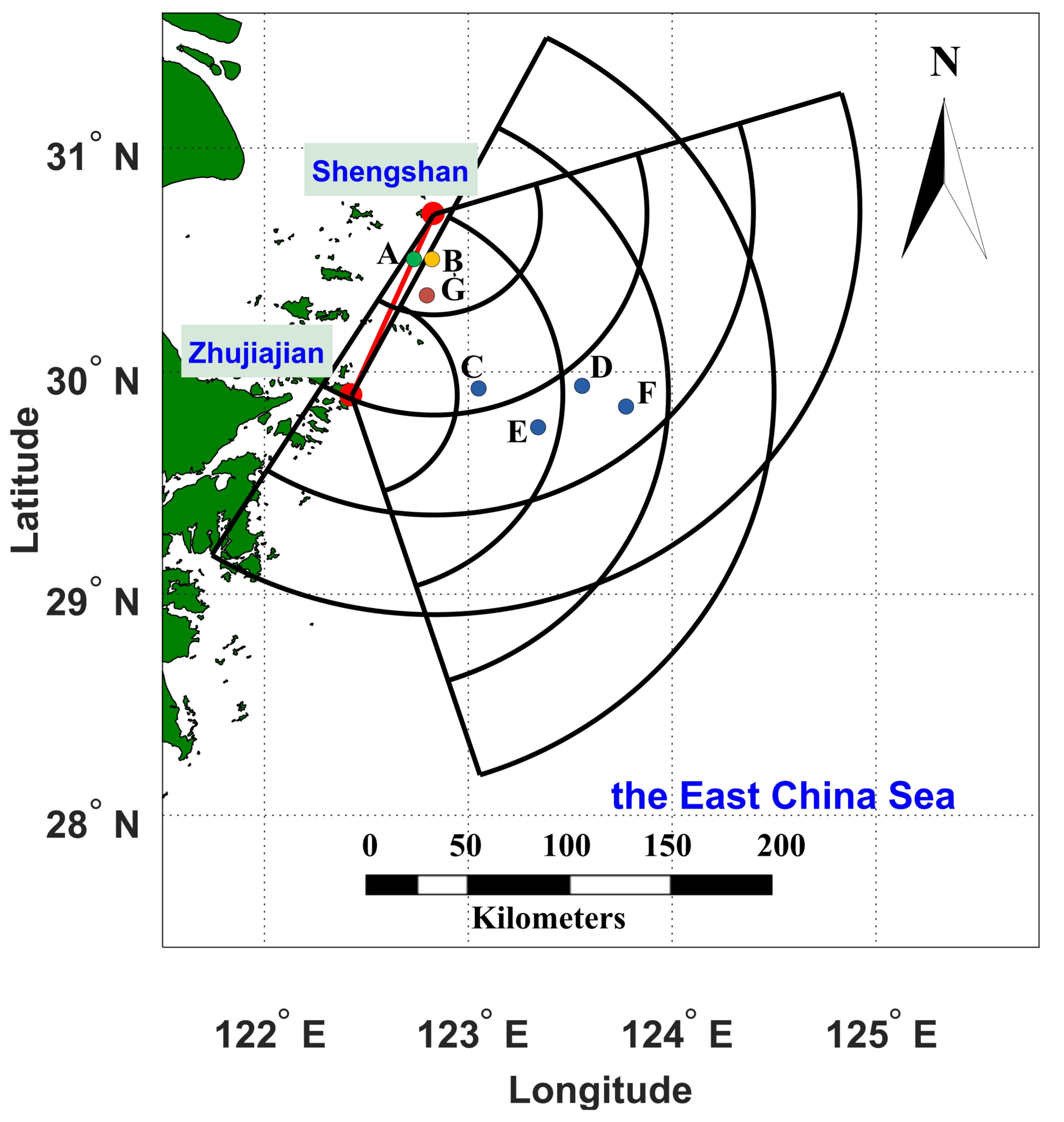
The map in Figure 9 shows that Point A is located on the baseline of the Zhujiajian and Shengshan sites. Assuming that the current speed and direction at Point A are v and , respectively, then the radial currents measured by the Shengshan and Zhujiajian MHF-C radars, denoted as and , respectively, are equal to the following:
where is the direction of the baseline. Obviously, . This relationship facilitates the comparison of the radial currents between the two Shengshan and Zhujiajian radars to assess the performance of MHF-C radar.
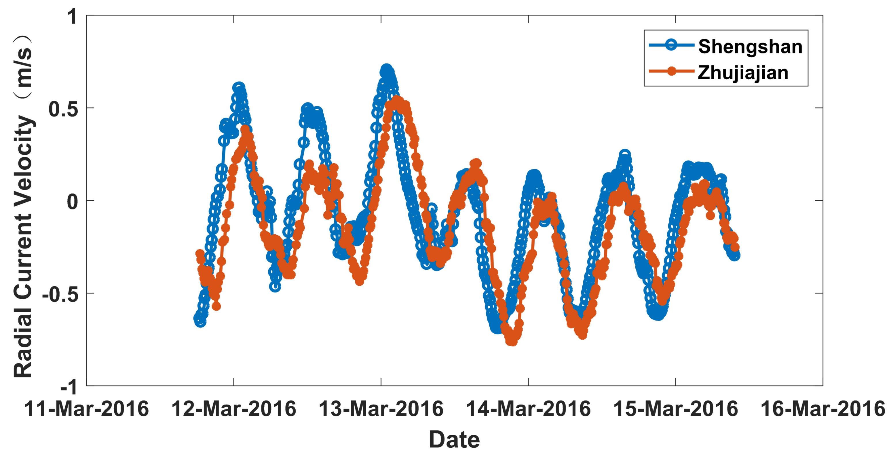
Figure 10 displays the comparison of the radial current series derived from the Shengshan and Zhujiajian radars at Point B, which is located close to Point A during Observation Period I. Moreover, the Zhujiajian radial current values have an added minus sign. The radial current measurements at Point B are utilized for this comparison instead of Point A because Point A is outside of radar coverage. The CC and RMS difference of this comparison are 0.81 and 0.2 m/s, respectively. Figure 11 shows the same type of comparison at Point B during Observation Period II, with a CC of 0.77 and a RMS difference of 0.23 m/s. A good performance of both the Shengshan and Zhujiajian MHF-C radars is likely required to generate the consistency between the series in Figure 10 and Figure 11.
3.4. Comparisons between Radars and ADCPs
In April 2015, we performed an experiment to evaluate the current measurement performance of MHF-C radars using in situ equipment. The staff drove a ship and deployed an ADCP at Point C, D, E and F shown in Figure 9. At each point, the ship stayed for a 25-h observation. The distances from the radar sites to the in situ observation points are shown in Table 3. Only the MHF radar measurements at operating frequencies below 10 MHz are reported because these locations were far away for operating frequencies over 10 MHz to sense currents. Previous literature estimated that the HF radar can sense currents at a depth of ( is radio wavelength), or approximately 4% of the radio wavelength using linear current profiles [11]. Thus, 7.88 MHz and 8.27 MHz data provide currents at an approximate depth of 1.5 m.
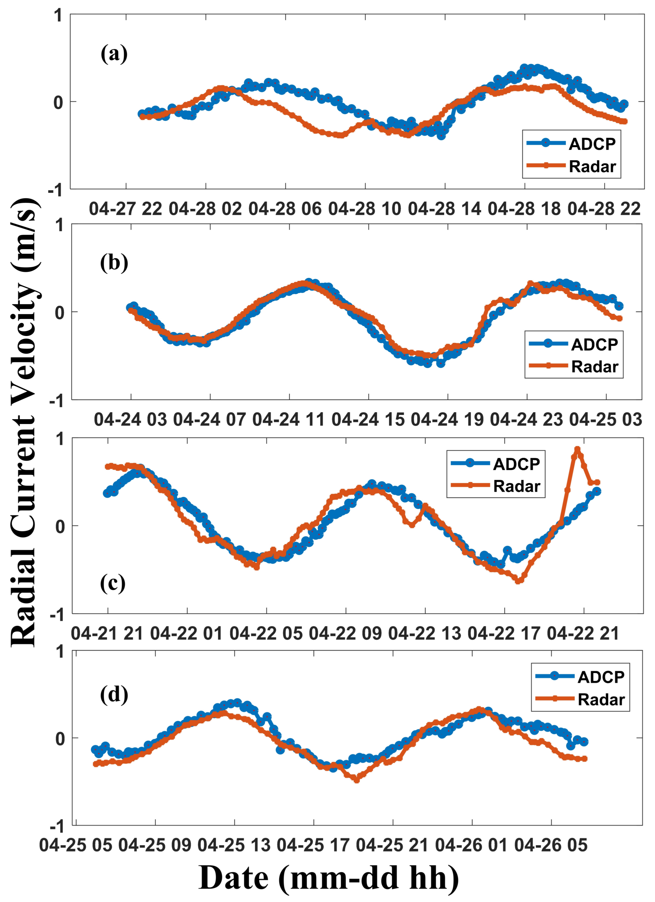
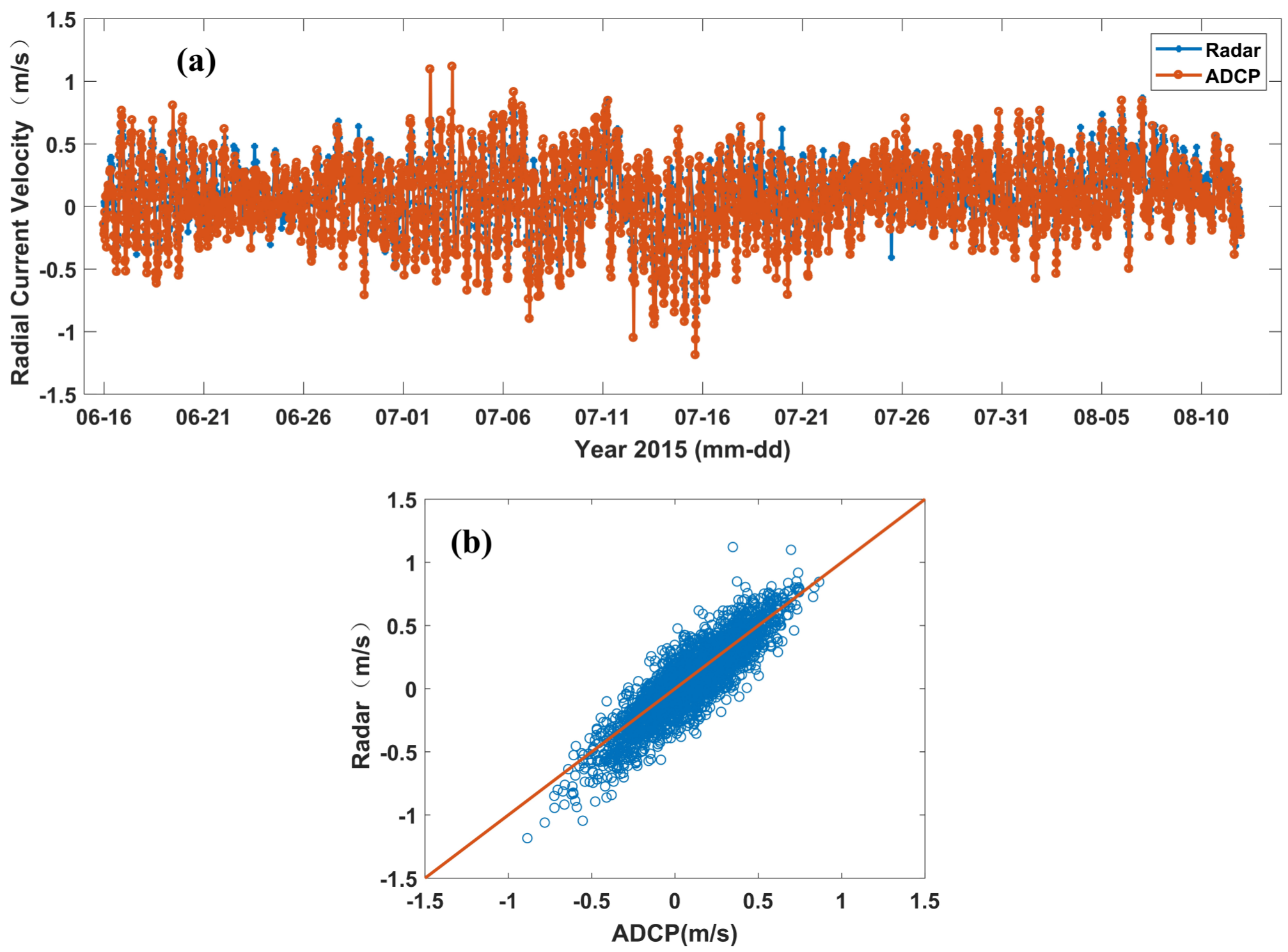
A buoy-mounted downward-looking ADCP provided the current vector profiles from approximately 2 m depth to 10 m depth at a resolution of 0.5 m and an interval of 5 min at these points. The MHF-C radar provides current maps every 10 min, and for convenience, the ADCP-derived currents at 3 m depth are averaged every 10 min. Figure 12 shows radial current comparisons using the Zhujiajian MHF-C radar during Observation Period IV, and Figure 13 shows the radial current comparisons using the Shengshan MHF-C radar. The RMS differences of these comparisons are shown in Table 3, with CC varying from 0.85 to 0.96 and root mean square error (RMSE) ranging from 0.07 m/s to 0.14 m/s. Another radial current comparison was conducted in Observation Period III at Point G, and the results are shown in Figure 14, with a CC of 0.91 and a RMSE of 0.13 m/s. A buoy-mounted downward-looking ADCP provided the current profiles at an interval of 30 min at Point G, and the ADCP-derived currents at 3 m depth were adopted. These comparisons demonstrate that the MHF-C radar is capable of measuring sea surface currents with reasonable performance.
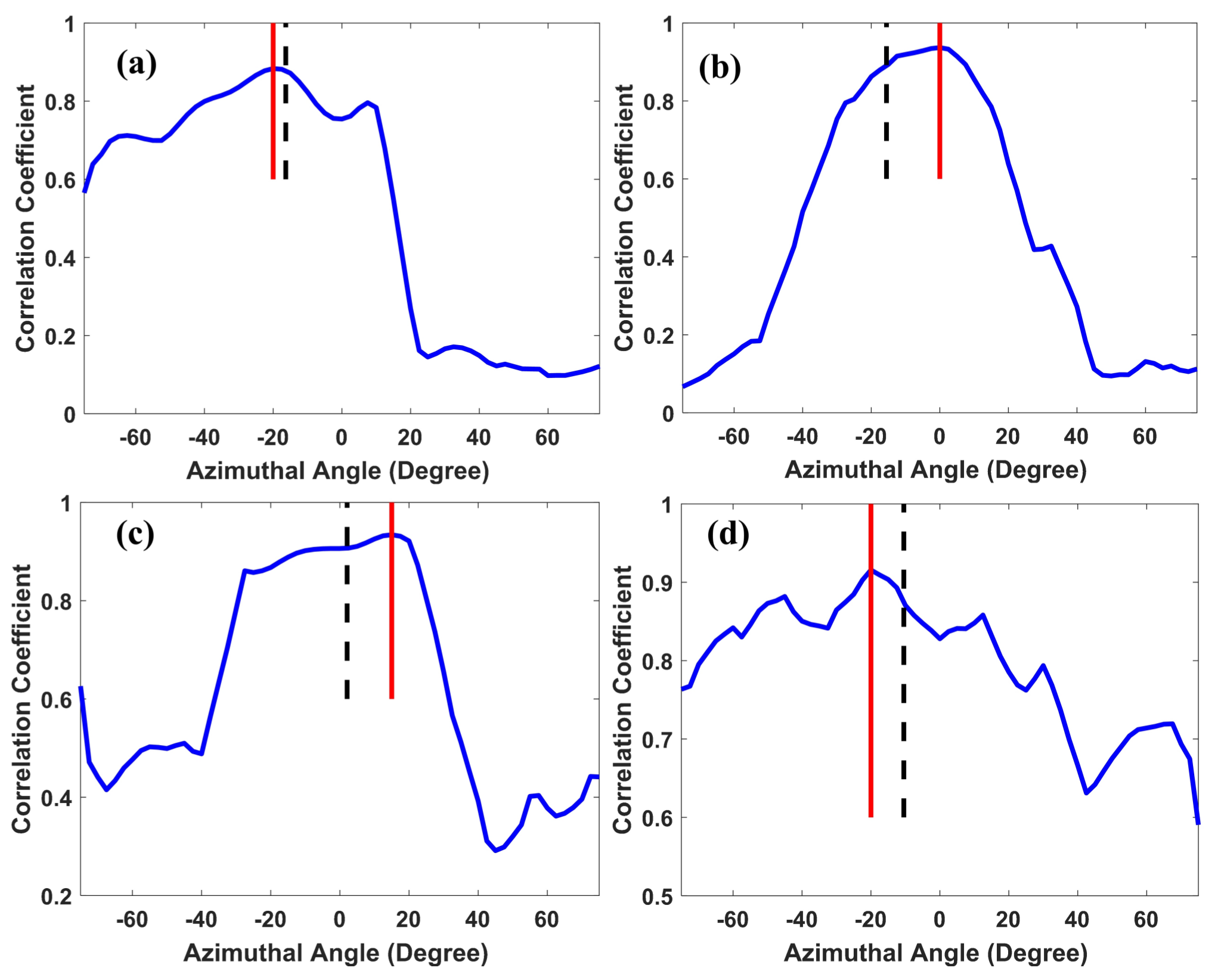
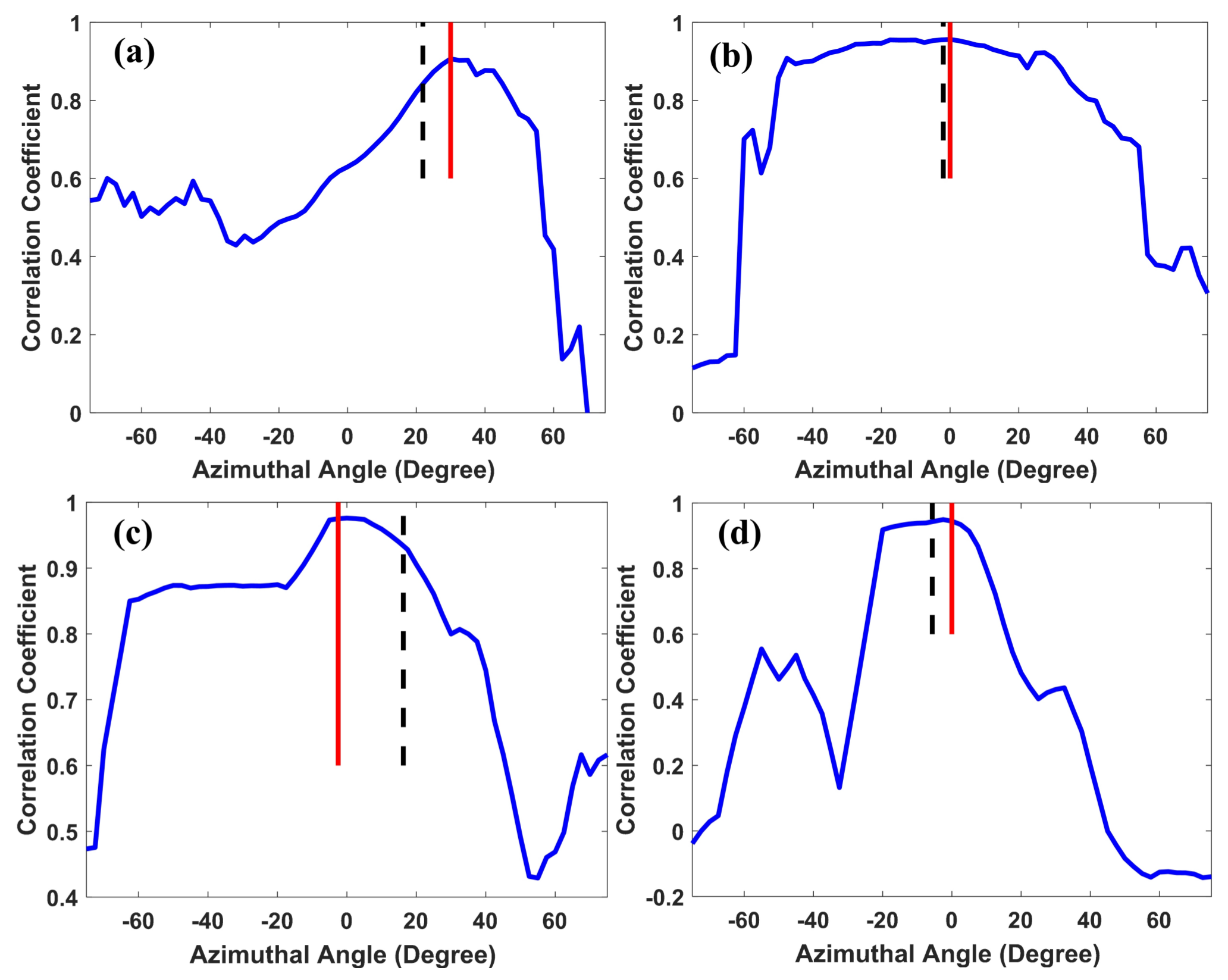
We also calculate the bearing offset using CCs between the ADCP-derived and HF radar-derived radial velocities at a fixed range (ADCP deployed) and all angles [33]. The bearing offset is thus expressed as:
where is the bearing angle closest in angle to the ADCP, and is the angle with the maximum CC.
The CC profiles of the Shengshan MHF-C radar radial current measurements are shown in Figure 15 with bearing offset angles that vary from 2.5 to 20 . Figure 16 shows the CC profiles of the Zhujiajian MHF-C radar radial current measurements with bearing offset angles that vary from 2.5 to 15 . The results show that small bearing offsets exist in the radial current measurements.
4. Discussion
The percent coverage map of radial currents shows the real coverage of the Shengshan and Zhujiajian MHF-C radars. Both of the radars have similar detection ranges and an percent coverage of approximately 90% at the range of 150 km for an operating frequency of approximately 8 MHz. Because large hills surround the Shengshan and Zhujiajian radar sites, the azimuthal ranges of the two systems assessed by the percent coverage map are approximately 150 . The field of view becomes larger than the previous type of MHF radar that was installed at the Shengshan site with typical in azimuth [30]. The improvement in the field of view also provides us with a direct way to evaluate the current measurement performance using a radar-to-radar comparison. This type of verification could not be conducted on the previous type of MHF radar that was installed at the same sites.
The MHF-C radar is capable of simultaneously providing current maps with multiple operating frequencies, different range resolutions and various depths, and the comparison between the two operating frequencies illustrates that making use of different operating frequencies to sense the ocean patch achieves similar measurements, with the Shengshan MHF-C radar nearly maintaining the same sampling performance when it steers from −75 to 70 . However, small differences are observed between the current measurements obtained from the 8.27 MHz and 19.20 MHz data, which may be caused by their different sampling range resolutions (5 km for 8.27 MHz and 1 km for 19.20 MHz). The depth of the measured current, which depends on the operating frequency, is another factor underlying the differences in measurements.
Comparisons of radial current measurements at five locations with a total duration of approximately sixty days between MHF-C radar and ADCP were conducted. The results illustrate that the utilization of the circular receiving array based on phase direction-finding mode provides current measurements with CC values that vary from 0.85 to 0.96 and RMSE values that range from 0.07 m/s to 0.14 m/s at different locations. Similar levels of current measurement performance were preliminarily obtained compared to other types of HF radar that have been reported in previous literature [10,30]. This type of compact design and signal processing method provides a practicable way to generate HF radar remotely sensed current maps.
5. Conclusions
This paper has introduced the MHF-C radar system, which has been the focus of our research over the past five years. The basic principles of the multiple operating frequencies and the design of a circular array are presented. The performance of current measurements using a circular receiving array is investigated by frequency-to-frequency, radar-to-radar, and radar-to-ADCP comparisons. Small pointing errors still exist in the system. In future work, we plan to find the causes of pointing errors and improve the performance of the circular receiving array.
Acknowledgments
This work was supported in part by the National Natural Science Foundation of China under Grant No. 41506201 and No. 41376182; in part by the Public Science and Technology Research Funds Projects of Ocean under Grant No. 201205032; in part by the National Key Research and Development Plan No. 2017YFF0206404 and No. 2016YFC1400504; and in part by the Project of Hubei Province Science and Technology Support Program under Grant No. 2014BEC057.
Author Contributions
Chen Zhao developed the method to extract currents and participated in the experiment; Zezong Chen designed the MHF-C system; Chao He, Fei Xie and Xi Chen participated in the experiment and data processing; and Changqing Mou participated in the experiment.
Conflicts of Interest
The authors declare no conflict of interest.
Abbreviations
The following abbreviations are used in this manuscript:
| HF | High Frequency |
| WERA | WEllen RAdar |
| MCR | Multi-frequency Coastal Radar |
| RORSE | Radio Ocean Remote SEnsing |
| MHF | multi-frequency HF |
| DOA | direction of arrival |
| MUSIC | MUltiple SIgnal Characterization |
| FMICW | Frequency Modulated Interrupted Continuous Wave |
| FFT | Fast Fourier Transformation |
| SWR | standing-wave ratio |
| ADCPs | Acoustic Doppler Current Profilers |
| SNR | Signal to Noise Ratio |
| RMS | Root Mean Square |
| CC | correlation coefficient |
| RMSE | root mean square error |
References
- Barrick, D.E. First-Order Theory and Analysis of MF/HF/VHF Scatter from the Sea. IEEE Trans. Antennas Propag. 1972, 20, 2–10. [Google Scholar] [CrossRef]
- Anderson, S.J. Optimizing HF Radar Siting for Surveillance and Remote Sensing in the Strait of Malacca. IEEE Trans. Geosci. Remote Sens. 2013, 51, 1805–1816. [Google Scholar] [CrossRef]
- Kirincich, D.E.; Paolo, T.; Terrill, E. Improving HF Radar Estimates of Surface Currents Using Signal Quality Metrics, with Application to the MVCO High-Resolution Radar System. IEEE Trans. Antennas Propag. 2011, 29, 1377–1390. [Google Scholar] [CrossRef]
- Lipa, B.J.; Barrick, D.E. Least-squares methods for the extraction of surface currents from CODAR crossed-loop data. IEEE J. Ocean. Eng. 1983, 8, 226–253. [Google Scholar] [CrossRef]
- Huang, W.; Wu, S.; Gill, E.W.; Wen, B.; Yang, Z.; Hou, J. HF radar wind and wave measurement over the Eastern China Sea. IEEE Trans. Geosci. Remote Sens. 2002, 40, 1950–1955. [Google Scholar] [CrossRef]
- Wyatt, L.R.; Green, J.J.; Middleditch, A.; Moorhead, M.D.; Howarth, J.; Holt, M.; Keogh, S. Operational Wave, Current, and Wind Measurements With the Pisces HF Radar. IEEE J. Ocean. Eng. 2006, 31, 819–834. [Google Scholar] [CrossRef]
- Liu, Y.G.; Weisberg, R.H.; Merz, C.R. Assessment of CODAR SeaSonde and WERA HF Radars in Mapping Surface Currents on the West Florida Shelf. J. Atmos. Ocean. Technol. 2014, 31, 1363–1382. [Google Scholar] [CrossRef]
- Shay, L.K.; Martinez-Pedraja, J.; Cook, T.M.; Haus, B.K.; Weisberg, R.H. High-Frequency Radar Mapping of Surface Currents Using WERA. J. Atmos. Ocean. Technol. 2007, 24, 484–503. [Google Scholar] [CrossRef]
- Stanev, E.V.; Ziemer, F.; Schulz-Stellenfleth, J.; Seemann, J.; Staneva, J.; Gurgel, K.W. Blending Surface Currents from HF Radar Observations and Numerical Modeling: Tidal Hindcasts and Forecasts. J. Atmos. Ocean. Technol. 2015, 32, 256–281. [Google Scholar] [CrossRef]
- Paduan, J.D.; Washburn, L. High-frequency radar observations of ocean surface currents. Annu. Rev. Mar. Sci. 2013, 5, 115–136. [Google Scholar] [CrossRef] [PubMed]
- Stewart, R.H.; Joy, J.W. HF radio measurements of surface currents. Deep-Sea Res. 1974, 21, 1039–1049. [Google Scholar] [CrossRef]
- Teague, C.C.; Vesecky, J.F.; Hallock, Z.R. A comparison of Multifrequency HF Radar and ADCP Measurements of Near-Surface Currents During COPE-3. IEEE J. Ocean. Eng. 2001, 26, 399–405. [Google Scholar] [CrossRef]
- Chen, Z.; Zhao, C.; Jiang, Y.; Hu, W. Wave Measurements with Multi-Frequency HF radar in the East China Sea. J. Electromagn. Waves Appl. 2011, 25, 1031–1043. [Google Scholar] [CrossRef]
- Paolo, T.D.; Terrill, E. Skill assessment of resolving ocean surface current structure using compact-antenna-style HF radar and the MUSIC direction-finding algorithm. J. Atmos. Ocean. Technol. 2007, 24, 1277–1300. [Google Scholar] [CrossRef]
- Laws, K.E.; Fernandez, D.M.; Paduan, J.D. Simulation based evaluations of HF radar ocean current algorithms. IEEE J. Ocean. Eng. 2000, 25, 481–491. [Google Scholar] [CrossRef]
- Emery, B.M.; Washburn, L.; Harlan, J.A. Evaluating radial current measurements from CODAR high-frequency radars with moored current meters. J. Atmos. Ocean. Technol. 2004, 21, 1259–1271. [Google Scholar] [CrossRef]
- Kohut, J.T.; Roarty, H.J.; Glenn, S.M. Characterizing Observed Environmental Variability With HF Doppler Radar Surface Current Mappers and Acoustic Doppler Current Profilers: Environmental Variability in the Coastal Ocean. IEEE J. Ocean. Eng. 2006, 31, 876–884. [Google Scholar] [CrossRef]
- Lorente, P.; Soto-Navarro, J.; Fanjul, E.A.; Piedracoba, S. Accuracy assessment of high frequency radar current measurements in the Strait of Gibraltar. J. Oper. Oceanogr. 2014, 7, 59–73. [Google Scholar] [CrossRef]
- Robinson, A.M.; Wyatt, L.R.; Howarth, M.J. A two year comparison between HF radar and ADCP current measurements in Liverpool Bay. J. Oper. Oceanogr. 2011, 4, 33–45. [Google Scholar] [CrossRef]
- Cosoli, S.; Bolzon, G. Accuracy of surface current mapping from High-Frequency (HF) ocean radars. Boll. Geofis. Teor. Appl. 2015, 56, 55–70. [Google Scholar]
- Liu, Y.; Weisberg, R.H.; Merz, C.R.; Lichtenwalner, S.; Kirkpatrick, G.J. HF Radar Performance in a Low-Energy Environment: CODAR SeaSonde Experience on the West Florida Shelf. J. Atmos. Ocean. Technol. 2010, 27, 1689–1710. [Google Scholar] [CrossRef]
- Kaplan, D.M.; Largier, J.; Botsford, L.W. HF radar observations of surface circulation off Bodega Bayn (northern California, USA). J. Geophys. Res. 2005, 110, C10020. [Google Scholar] [CrossRef]
- Bellomo, L.; Griffa, A.; Cosoli, S.; Falco, P.; Gerin, R.; Iermano, I.; Kalampokis, A.; Kokkini, Z.; Lana, A.; Magaldi, M.G.; et al. Toward an integrated HF radar network in the Mediterranean Sea to improve search and rescue and oil spill response: The TOSCA project experience. J. Oper. Oceanogr. 2015, 8, 95–107. [Google Scholar] [CrossRef]
- Molcard, A.; Poulain, P.M.; Forget, P.; Griffa, A.; Barbin, Y.; Gaggelli, J.; De Maistre, J.C.; Rixen, M. Comparison between VHF radar observations and data from drifter clusters in the Gulf of La Spezia (Mediterranean Sea). J. Mar. Syst. 2009, 78, S79–S89. [Google Scholar] [CrossRef]
- Kokkini, Z.; Potiris, M.; Kalampokis, A.; Zervakis, V. HF Radar observations of the Dardanelles outflow current in North Eastern Aegean using validated WERA HF radar data. Mediterr. Mar. Sci. 2014, 15, 753–768. [Google Scholar] [CrossRef]
- Kalampokis, A.; Uttieri, M.; Poulain, P.M.; Zambianchi, E. Validation of HF radar-derived currents in the Gulf of Naples with Lagrangian data. IEEE Geosci. Remote Sens. Lett. 2016, 13, 1452–1456. [Google Scholar] [CrossRef]
- Flores-Vidal, X.; Flament, P.; Durazo, R.; Chavanne, C.; Gurgel, K.-W. High-frequency radars: Beamforming calibrations using ships as reflectors. J. Atmos. Ocean. Technol. 2013, 30, 638–648. [Google Scholar] [CrossRef]
- Zhao, C.; Chen, Z.; Jiang, Y.; Fan, L.; Zeng, G. Exploration and Validation of Wave-Height Measurement Using Multifrequency HF Radar. J. Atmos. Ocean. Technol. 2013, 30, 2189–2202. [Google Scholar]
- Zhao, C.; Chen, Z.; Zeng, G.; Zhang, L. A new multi-frequency HF radar system based on small circular antenna array for sea surface current measurement. In Proceedings of the IEEE Oceans Conference, Shanghai, China, 10 April 2016; pp. 1–5. [Google Scholar]
- Zhao, C.; Chen, Z.; Zeng, G.; Zhang, L.; Xie, F. Evaluating Radial Current Measurement of Multi-frequency HF radar with Multi-depth ADCP Data during a small storm. J. Atmos. Ocean. Technol. 2015, 32, 1071–1087. [Google Scholar] [CrossRef]
- Zhao, C.; Chen, Z.; Zeng, G.; Zhang, L. Evaluating Two Array Auto-calibration Methods with Multi-frequency HF Radar Current Measurements. J. Atmos. Ocean. Technol. 2015, 32, 1088–1097. [Google Scholar] [CrossRef]
- Chen, Z.; Zeng, G.; Zhao, C.; Zhang, L. A phase error estimation method for broad beam High-Frequency radar. IEEE Geosci. Remote Sens. Lett. 2015, 12, 1526–1530. [Google Scholar] [CrossRef]
- Paduan, J.D.; Kim, K.C.; Cook, M.S.; Chavez, F.P. Calibration and Validation of Direction-Finding High-Frequency Radar Ocean Surface Current Observations. IEEE J. Ocean. Eng. 2007, 31, 862–875. [Google Scholar] [CrossRef]
Figure 1.
Circular receiving array with seven elements.
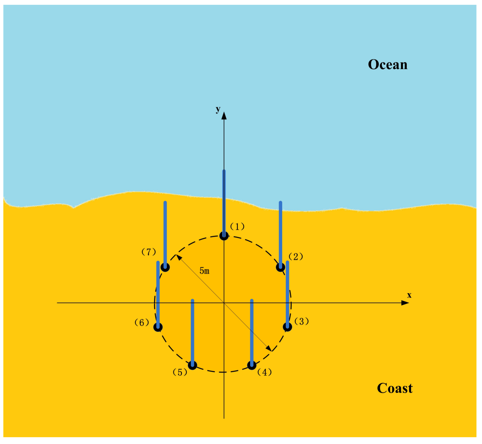
Figure 2.
Spatial coverage of the radial current measurements of the Shengshan radar at 8.27 MHz from 11 March to 15 March 2016.
Figure 2.
Spatial coverage of the radial current measurements of the Shengshan radar at 8.27 MHz from 11 March to 15 March 2016.

Figure 3.
Spatial coverage of the radial current measurements of the Zhujiajian radar at 7.88 MHz from 11 March to 15 March 2016.
Figure 3.
Spatial coverage of the radial current measurements of the Zhujiajian radar at 7.88 MHz from 11 March to 15 March 2016.
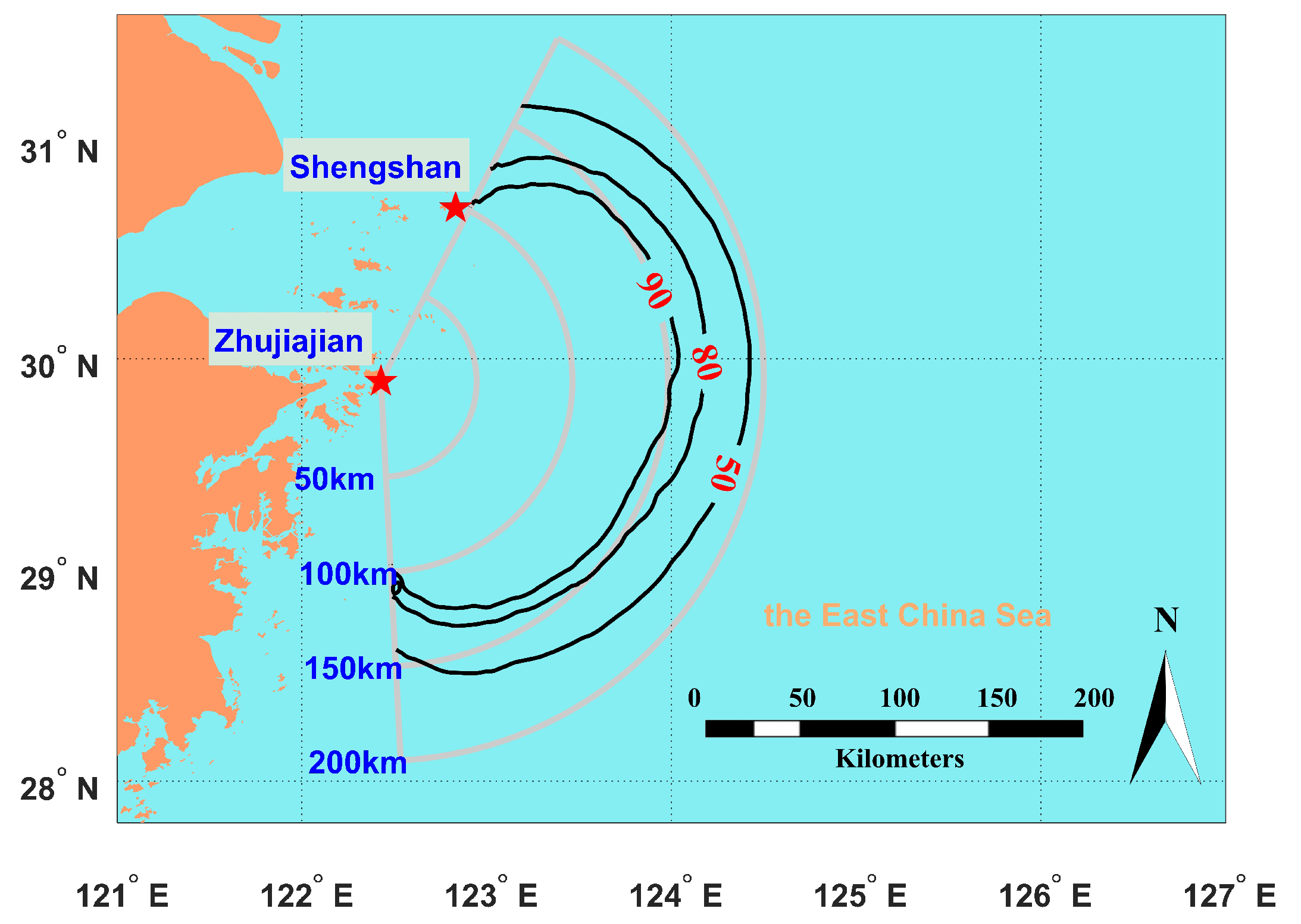
Figure 4.
Map of the comparisons between the 8.27 MHz and 19.20 MHz measurements by the Shengshan radar.
Figure 4.
Map of the comparisons between the 8.27 MHz and 19.20 MHz measurements by the Shengshan radar.
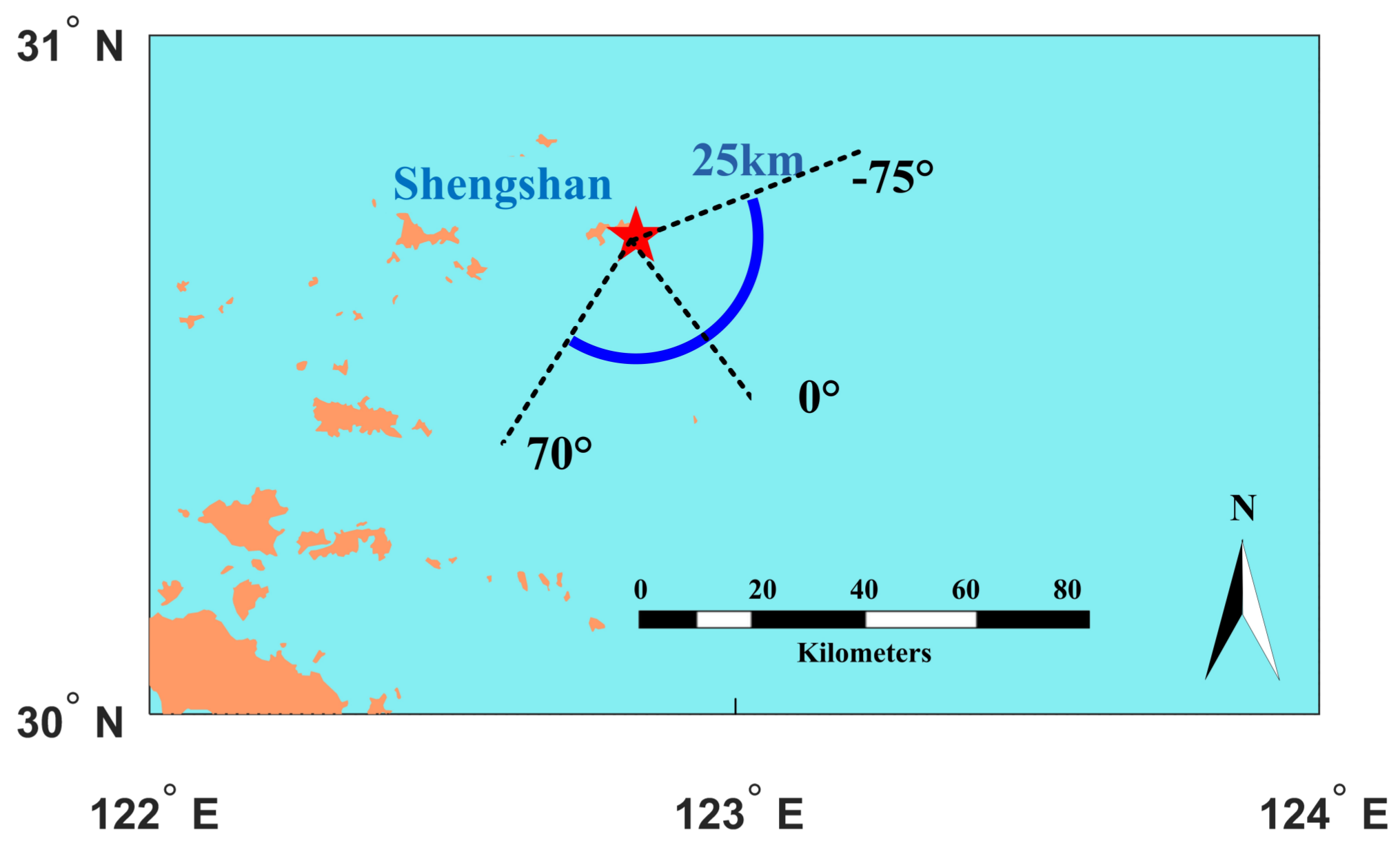
Figure 5.
For Observation Period I, a comparison of the radial current time series derived from frequency 1 (8.27 MHz) and frequency 2 (19.20 MHz) at the range of 25 km and azimuthal cells of: (a) −75 ; (b) −45 ; (c) −30 ; (d) 0 ; (e) 15 ; and (f) 45.
Figure 5.
For Observation Period I, a comparison of the radial current time series derived from frequency 1 (8.27 MHz) and frequency 2 (19.20 MHz) at the range of 25 km and azimuthal cells of: (a) −75 ; (b) −45 ; (c) −30 ; (d) 0 ; (e) 15 ; and (f) 45.
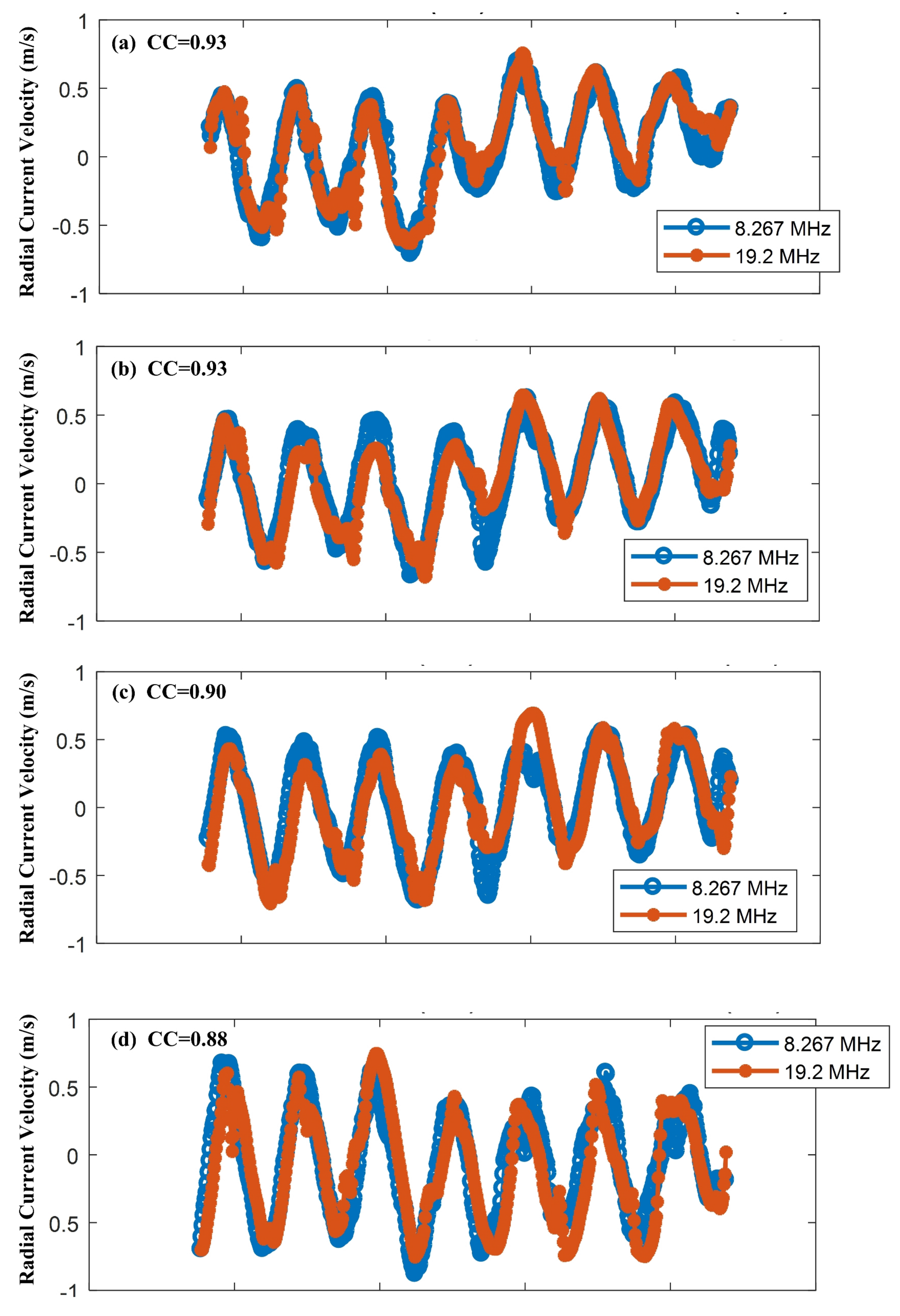

Figure 6.
For Observation Period I, CCs and RMS differences of the radial current measurements at different azimuthal angles.
Figure 6.
For Observation Period I, CCs and RMS differences of the radial current measurements at different azimuthal angles.
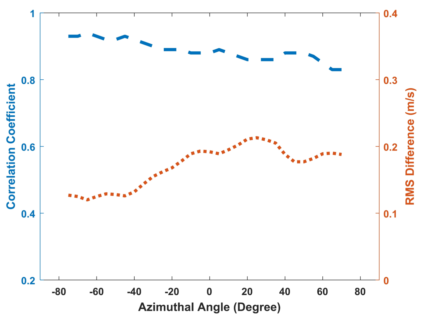
Figure 7.
For Observation Period II, a comparison of the radial current time series derived from frequency 1 (8.27 MHz) and frequency 2 (19.20 MHz) at a range of 25 km and azimuthal cells of: (a) −75 ; (b) −45 ; (c) −30 ; (d) 0 ; (e) 15 ; and (f) 45.
Figure 7.
For Observation Period II, a comparison of the radial current time series derived from frequency 1 (8.27 MHz) and frequency 2 (19.20 MHz) at a range of 25 km and azimuthal cells of: (a) −75 ; (b) −45 ; (c) −30 ; (d) 0 ; (e) 15 ; and (f) 45.
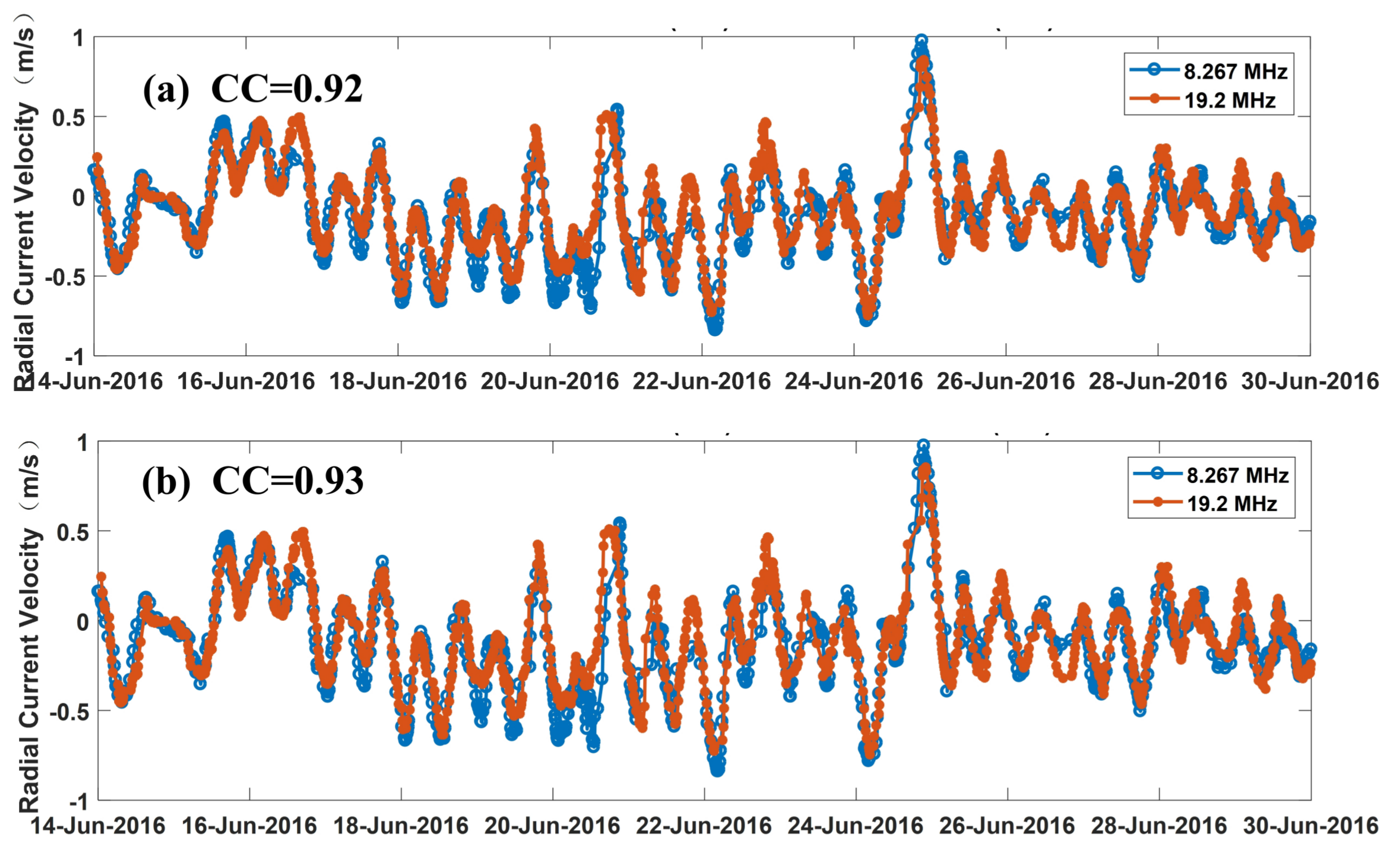
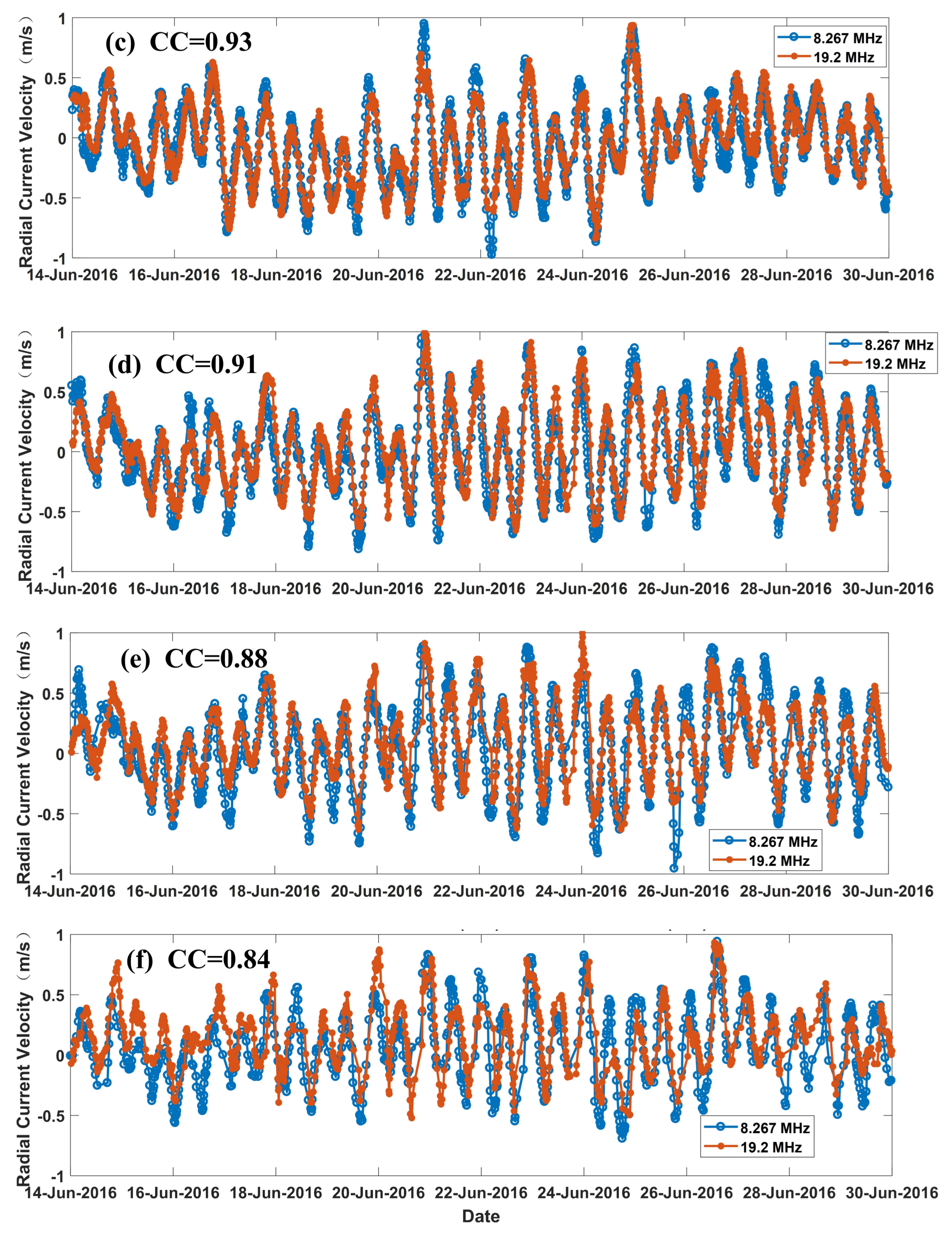
Figure 8.
For Observation Period II, CCs and RMS differences of the radial current measurements at different azimuthal angles.
Figure 8.
For Observation Period II, CCs and RMS differences of the radial current measurements at different azimuthal angles.
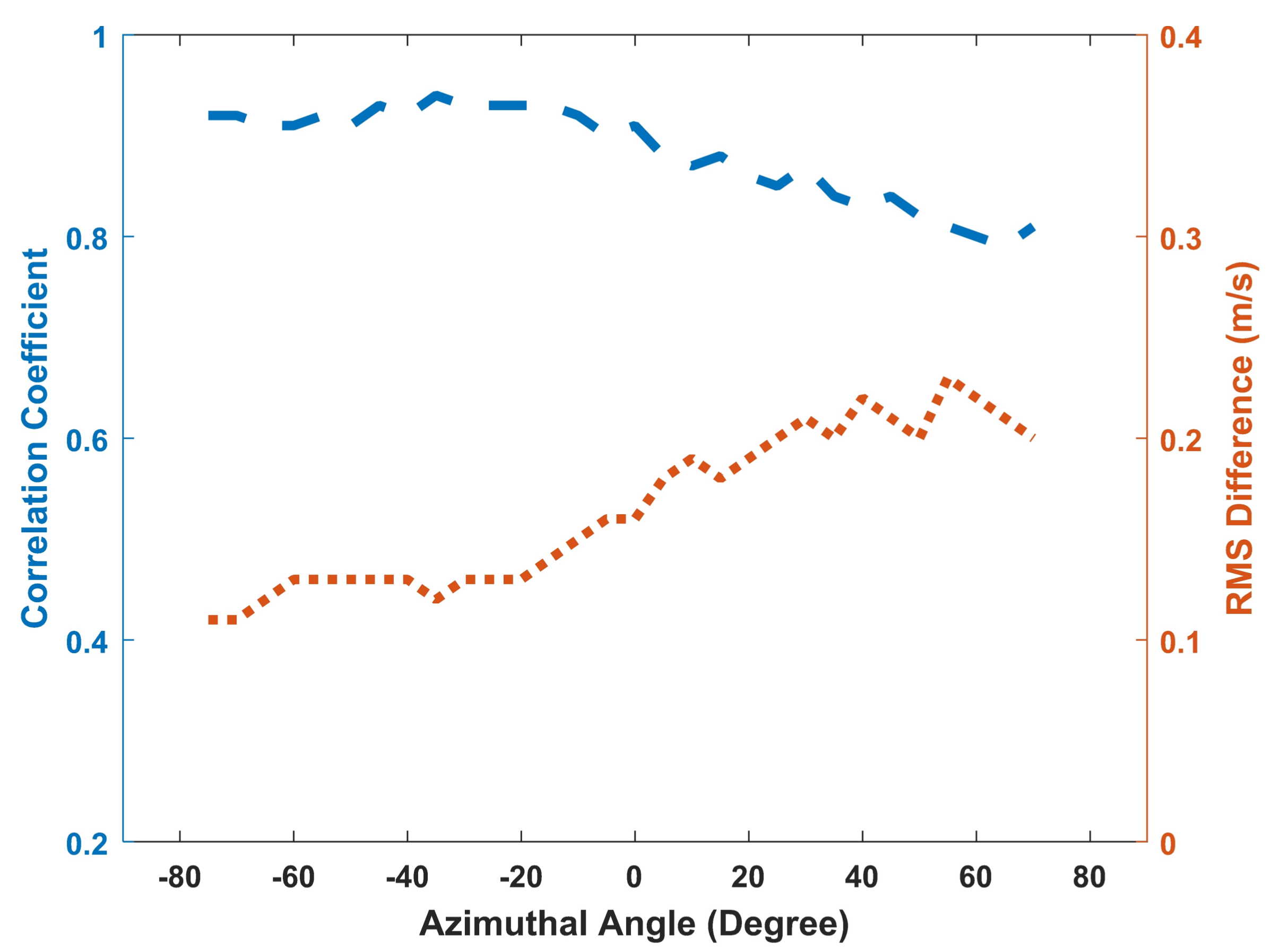
Figure 9.
Experiment setup for the Shengshan and Zhujiajian MHF radars.

Figure 10.
For Observation Period I, a comparison between the radial current series derived from the Shengshan and Zhujiajian radars at Point B; the Zhujiajian radial current values have an added minus sign.
Figure 10.
For Observation Period I, a comparison between the radial current series derived from the Shengshan and Zhujiajian radars at Point B; the Zhujiajian radial current values have an added minus sign.

Figure 11.
For Observation Period II, a comparison between the radial current series derived from the Shengshan and Zhujiajian radars at Point B; the Zhujiajian radial current values have an added minus sign.
Figure 11.
For Observation Period II, a comparison between the radial current series derived from the Shengshan and Zhujiajian radars at Point B; the Zhujiajian radial current values have an added minus sign.
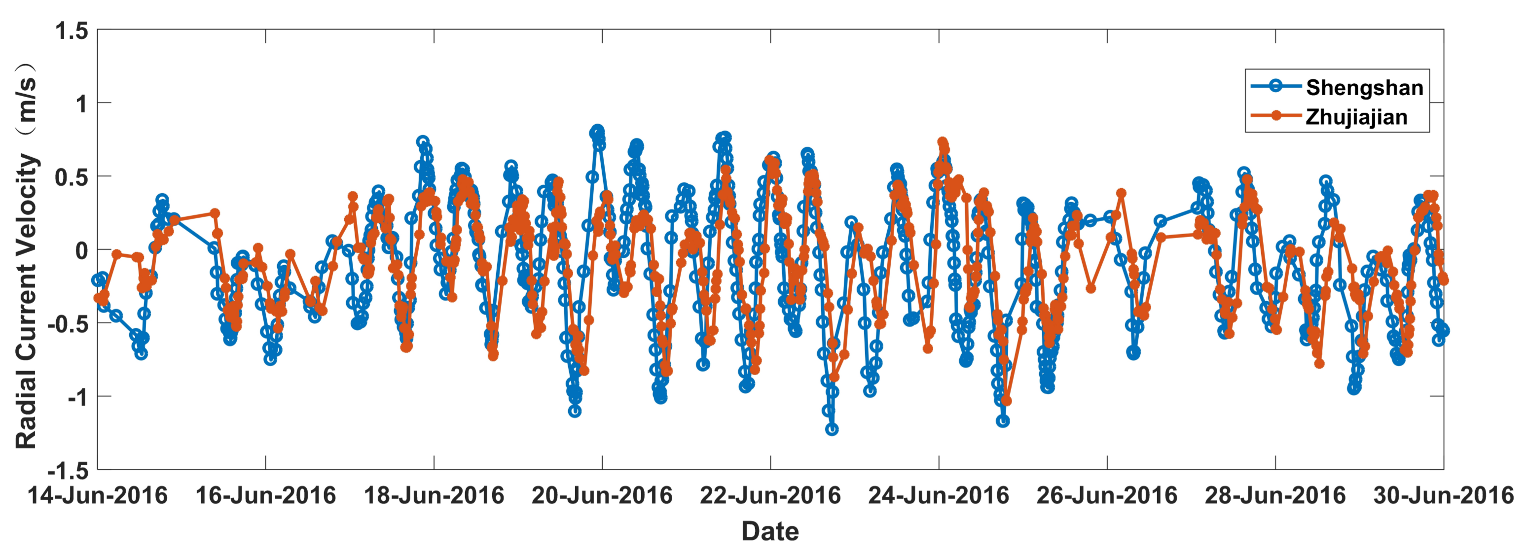
Figure 12.
Radial current comparisons using the Zhujiajian MHF-C radar at: (a) Point C; (b) Point D; (c) Point E; and (d) Point F.
Figure 12.
Radial current comparisons using the Zhujiajian MHF-C radar at: (a) Point C; (b) Point D; (c) Point E; and (d) Point F.
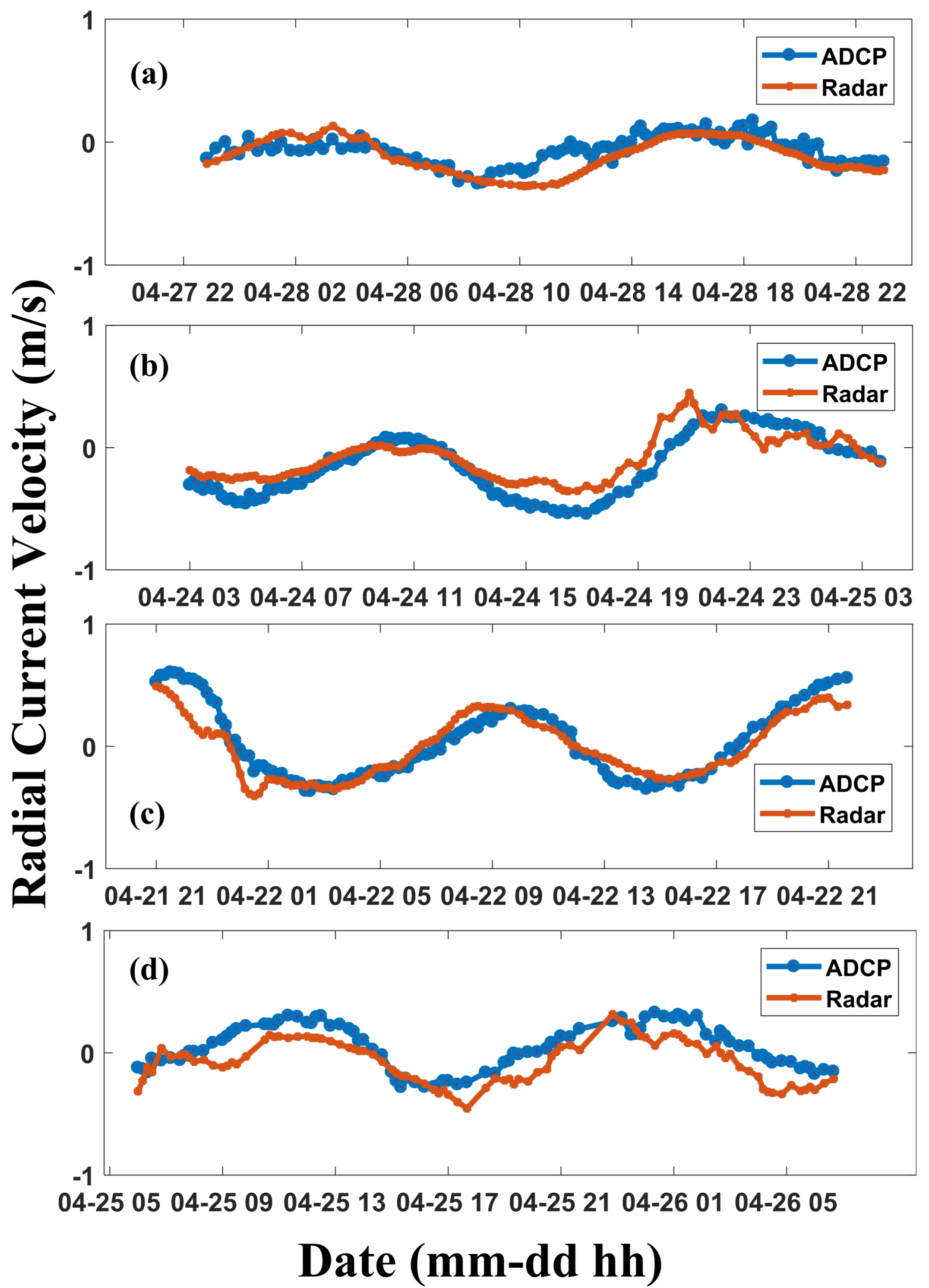
Figure 13.
Radial current comparisons using the Shengshan MHF-C radar at: (a) Point C; (b) Point D; (c) Point E; and (d) Point F.
Figure 13.
Radial current comparisons using the Shengshan MHF-C radar at: (a) Point C; (b) Point D; (c) Point E; and (d) Point F.

Figure 14.
Radial current comparisons using the Shengshan MHF-C radar at Point G during Observation Period III: (a) time series; and (b) scatter diagram.
Figure 14.
Radial current comparisons using the Shengshan MHF-C radar at Point G during Observation Period III: (a) time series; and (b) scatter diagram.

Figure 15.
The CC profiles of the Shengshan MHF-C radar radial current measurements at: (a) Point C with a bearing offset of 7.5; (b) Point D with a bearing offset of 2.5; (c) Point E with a bearing offset of 20; and (d) Point F with a bearing offset of 5. Red solid line indicates the angle with the maximum CC, and the black dashed line indicates the expected angle.

Figure 16.
The CC profiles of the Zhujiajian MHF-C radar radial current measurements at: (a) Point C with a bearing offset of 2.5; (b) Point D with a bearing offset of 15; (c) Point E with a bearing offset of 12.5; and (d) Point F with a bearing offset of 10. Red solid line indicates the angle with the maximum CC, and the black dashed line indicates the expected angle.

Table 1.
Capabilities of the MHF-C system.
| Parameter | Value |
|---|---|
| Operating frequency range (MHz) | 7.5–25 |
| Number of operating frequencies | ≤4 |
| Transmitter peak power (W) | 300 |
| Maximum detection range (km) | 200 |
| Range cell resolution (km) | 1–5 |
| Doppler sampling cycle (s) | 0.4–0.6 |
| Measurement cycle (min) | 10 |
Table 2.
Details of the data presented in the paper.
| Observation Period | Duration | Shengshan Site | Zhujiajian Site | ADCP | ||
|---|---|---|---|---|---|---|
| Frequency (MHz) | Range Resolution (km) | Frequency (MHz) | Range Resolution (km) | |||
| I | 11 March–15 March 2016 | 8.27 and 19.20 | 5 and 1 | 7.88 | 5 | None |
| II | 14 June–30 June 2016 | 8.27 and 19.20 | 5 and 1 | 7.88 | 5 | None |
| III | 16 June–12 August 2015 | 8.27 and 19.20 | 5 and 1 | None | None | Available |
| IV | 21 April–28 April 2015 | 8.27 and 19.20 | 5 and 1 | 7.88 | 5 | Available |
Table 3.
Comparisons of current measurements at different points.
| Point | Shengshan Site | Zhujiajian Site | ||||
|---|---|---|---|---|---|---|
| The Distance to the Point (km) | CC | RMSE (m/s) | The Distance to the Point (km) | CC | RMSE (m/s) | |
| C | 90 | 0.85 | 0.08 | 65 | 0.88 | 0.08 |
| D | 110 | 0.96 | 0.07 | 110 | 0.89 | 0.14 |
| E | 120 | 0.93 | 0.14 | 90 | 0.90 | 0.11 |
| F | 130 | 0.94 | 0.09 | 130 | 0.87 | 0.13 |
| G | 37 | 0.91 | 0.13 | None | None | None |
© 2018 by the authors. Licensee MDPI, Basel, Switzerland. This article is an open access article distributed under the terms and conditions of the Creative Commons Attribution (CC BY) license (http://creativecommons.org/licenses/by/4.0/).
Share and Cite
MDPI and ACS Style
Zhao, C.; Chen, Z.; He, C.; Xie, F.; Chen, X.; Mou, C. Validation of Sensing Ocean Surface Currents Using Multi-Frequency HF Radar Based on a Circular Receiving Array. Remote Sens. 2018, 10, 184. https://doi.org/10.3390/rs10020184
AMA Style
Zhao C, Chen Z, He C, Xie F, Chen X, Mou C. Validation of Sensing Ocean Surface Currents Using Multi-Frequency HF Radar Based on a Circular Receiving Array. Remote Sensing. 2018; 10(2):184. https://doi.org/10.3390/rs10020184
Chicago/Turabian StyleZhao, Chen, Zezong Chen, Chao He, Fei Xie, Xi Chen, and Changqing Mou. 2018. "Validation of Sensing Ocean Surface Currents Using Multi-Frequency HF Radar Based on a Circular Receiving Array" Remote Sensing 10, no. 2: 184. https://doi.org/10.3390/rs10020184
Note that from the first issue of 2016, this journal uses article numbers instead of page numbers. See further details here.