Review

Near-Space Microwave Radar Remote Sensing: Potentials and Challenge Analysis

1
School of Communication and Information Engineering, University of Electronic Science and Technology of China, 611731 Chengdu, China
2
The Institute of Plateau Meteorology (IPM), China Meteorological Administration (CMA), China
*
Author to whom correspondence should be addressed.
Remote Sens. 2010, 2(3), 717-739; https://doi.org/10.3390/rs2030717
Submission received: 16 November 2009 / Revised: 11 January 2010 / Accepted: 26 January 2010 / Published: 9 March 2010
(This article belongs to the Special Issue Microwave Remote Sensing)

Abstract

:
Near-space, defined as the region between 20 km and 100 km, offers many new capabilities that are not accessible to low earth orbit (LEO) satellites and airplanes, because it is above storm and not constrained by either the orbital mechanics of satellites or the high fuel consumption of airplanes. By placing radar transmitter/receiver in near-space platforms, many functions that are currently performed with satellites or airplanes could be performed in a cheaper way. Inspired by these advantages, this paper introduces several near-space vehicle-based radar configurations, such as near-space passive bistatic radar and high-resolution wide-swath (HRWS) synthetic aperture radar (SAR). Their potential applications, technical challenges and possible solutions are investigated. It is shown that near-space is a satisfactory solution to some specific remote sensing applications. Firstly, near-space passive bistatic radar using opportunistic illuminators offers a solution to persistent regional remote sensing, which is particularly interest for protecting homeland security or monitoring regional environment. Secondly, near-space provides an optimal solution to relative HRWS SAR imaging. Moreover, as motion compensation is a common technical challenge for the described radars, an active transponder-based motion compensation is also described.

1. Introduction

Current spaceborne and airborne radars have been playing an important role in remote sensing applications [1,2,3]; however, even as good as they are envisioned and employed, it is impossible to provide a staring presence on a timescale of days, weeks, or months over a selected target or area of interest. Even if we can launch a satellite for a particular application, it would only be in view for a short time. As an example, most low earth orbit (LEO) satellites have a specific target in view for less than 10 minutes at a time and revisit the same site infrequently. Persistent coverage by multiple satellite constellation costs as much as billions of US dollars, which is prohibitively expensive [4]. In contrast, conventional airplanes cannot fly too high because there will not be sufficient oxygen for the engines to operate. Generally, satellites usually operate in the orbits above 200 km, and air-breathing airplanes routinely operate at lower than 18 km. We thus have two gaps. The first is a gap in capability of persistent remote sensing observation. The second gap is the absence of sensors in the altitude between that of airplanes and satellites. To overcome these disadvantages, we should seek some alternative platforms.
Moreover, the requirements of stealth and robust survivability in military applications also call for new radar platforms other than satellites and airplanes [5]. Fortunately, those aims can be simultaneously obtained by near-space platforms at a fractional cost of the traditional platforms [6]. Near-space, defined as the region between 20 km and 100 km, is too high for conventional aircrafts and too low for LEO satellites. It offers many new capabilities that are critical to emerging remote sensing applications, but it is not accessible from satellites or airplanes. The near-space platforms, as considered in this paper, involves stationary vehicles and maneuvering vehicles flying in near-space where the wind is mild and weather is virtually non-existent [7,8]. More importantly, not constrained by orbital mechanics like satellites and high fuel consumption like airplanes, near-space platforms can stay at a specific site for a long time to provide a persistent region coverage.
A literature search in the area of near-space reveals that most work concentrated on designing near-space platforms including stationary vehicles and maneuvering vehicles [9,10]. Little work on the use of near-space sensors for communication and navigation applications has been reported [11,12]. Even less effort has been devoted to new radar imaging techniques based on near-space platforms [13]. In fact, by placing radar transmitter/receiver inside near-space platforms, many functions that are currently performed with satellites or airplanes could be performed in a cheaper. Inspired by recent advances in near-space technology and radar techniques [14,15], this paper describes several near-space radars for remote sensing applications. The system concepts, signal models and corresponding performance analysis are described, along with the potential applications, technical challenges and possible solutions.
The remaining sections are organized as follows. The superiorities of near-space platform are outlined in Section 2. Next, several near-space vehicle-based microwave remote sensing techniques including passive bistatic radar imaging and high-resolution and wide-swath (HRWS) SAR imaging, along with their potentials and challenges, are investigated in Section 3 and Section 4, respectively. Strict position and altitude information are required to ensure success, but high-precision motion measurement assets widely used in current radar systems may not be reachable for near-space platforms because of its limited load capability. Hence, motion compensation is investigated in Section 5, and an active transponder-based motion compensation is described. This paper is concluded in Section 6.

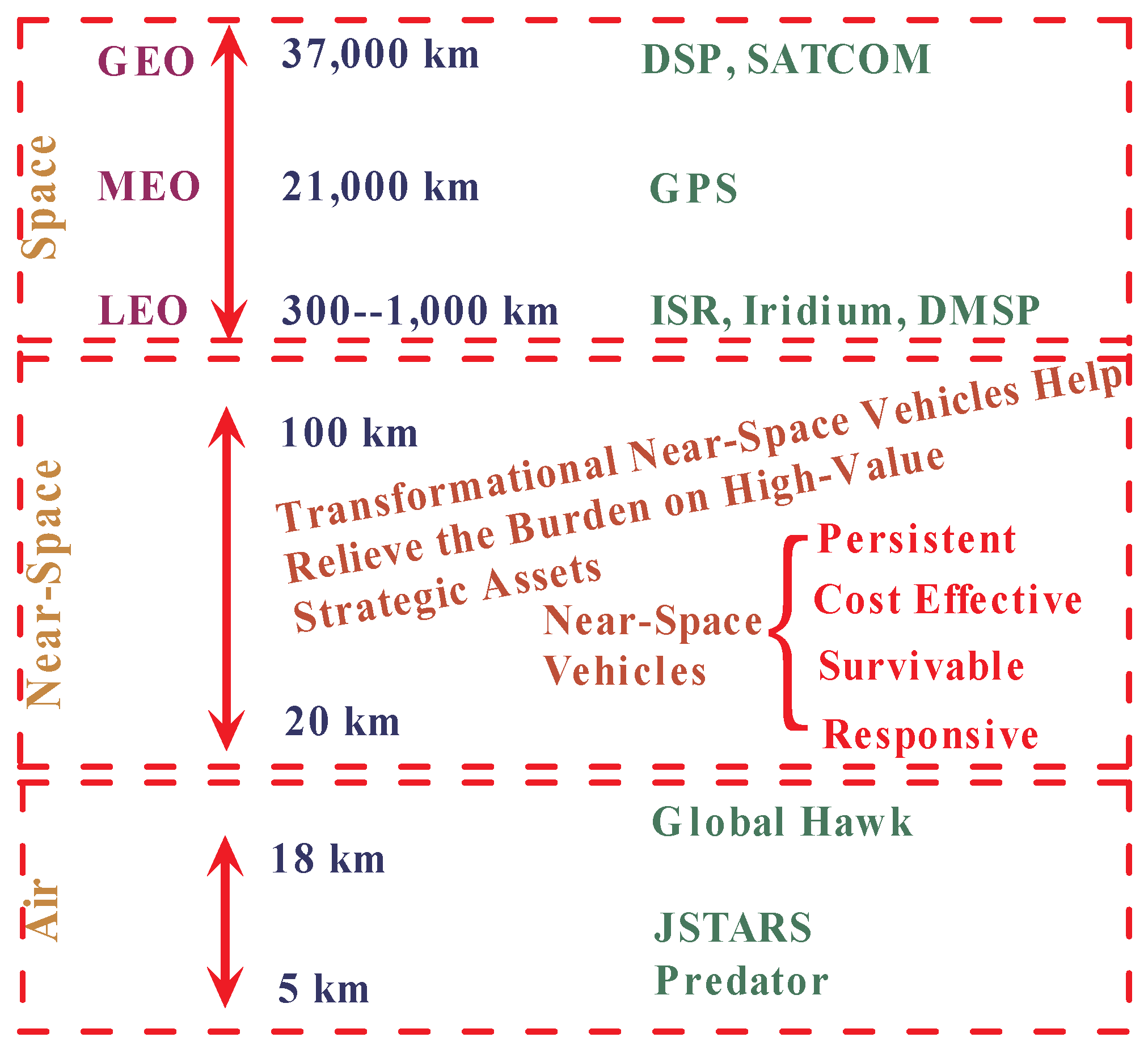
2. Superiorities of Near-Space Radar Platform

As shown in Figure 1, while compared to current satellite and airplane platforms, near-space platform has many superiorities for microwave remote sensing applications:
Figure 1. Near-space definition and its advantages while compared to space including geosynchronous earth orbit (GEO), middle earth orbit (MEO) and low earth orbit (LEO), and airspace.
Remotesensing 02 00717 g001

2.1. Persistent Region Coverage or Fast Re-Visiting Frequency

The first superiority of near-space platform is persistent region coverage or fast re-visiting frequency. Space technologies have revolutionized modern battlefield and remote sensing techniques greatly [16]; however, persistent coverage, which is highly desired, is still unavailable through satellites or airplanes. Table 1 shows the observation time for selected LEO orbits. Fortunately, these can be achieved by using near-space platforms. The altitude of near-space is above troposphere and atmosphere region where most weather occurs. There are no cloud, thunderstorm, or precipitation [17]. Moreover, propulsion technique can be applied to offset possible mild winds in near-space. Near-space stationary vehicles can stay at a specific site for a long time, so a persistent region coverage is possible. This advantage has a particular value for applications that require persistent monitoring. Such platforms are the functional cross between satellites and airplanes. They can fast-fly or station-keep over a specific position, to provide large footprint and long mission duration.
Table 1. Pass Times of LEO satellites.
Orbital Altitude(km)Maximum Pass Time (minutes:seconds)
Angle Above Horizon (degrees)
05103045
2007:495:374:081:401:00
3009:357:165:342:241:27
40011:108:446:543:081:54

2.2. Inherently Survivable

Near-space platforms, especially stationary vehicles, are inherently survivable. They have extremely small radar cross and thermal cross sections, making them relatively invulnerable to most traditional tracking and positioning methods. Estimates of stationary vehicle’s radar cross sections (RCS) are on the order of hundredths of a square meter. In fact, at near-space altitude, stationary vehicles will be small optical targets, only showing up well when the background is much darker than them. Consequently, the acquisition and tracking problem will be very difficult, even without considering what sort of weapon could reach them. Surface-to-air missiles (SAMs) may be a threat, but they are most likely not designed to engage a non-maneuvering target at that altitude. Economics also discourage such as exchange because near-space vehicles are inexpensive.
Moreover, even if the acquisition and tracking problems are overcome, near-space sensors are difficult to destroy, particularly for the stationary vehicles. They are normally manufactured in two ways: zero-pressure and super-pressure. Zero-pressure ones are similar to hot air balloons. They are less vulnerable to puncture, since significant amount of the lifting gas must diffuse through the holes before the lift is lost. Imaging an inflated, lightweight plastic garment bag floating on the wind; even if there are many holes in such a bag, it can still float in the air for a long time. Super-pressure ones are inflated and sealed, much like a child’s toy helium balloon. However, most of them are generally constructed by strong and rip-stop material, which do not catastrophically deflate.

2.3. Low Cost

The inherent simplicity, recoverability, and relative less requirements of complex infrastructure all contribute to this advantage. Near-space platforms require extremely minimal launch infrastructure. Only a simple tie-down and an empty field are required, but complex launch infrastructure or even runway must be built for satellites and airplanes. Moreover, if the carried payloads have malfunctions, they can be brought back and repaired. When they become obsolete, they can be easily replaced. Additionally, not being exposed to electronic radiation common to space environment, payloads flown in near-space platforms require no costly space-hardening manufacture.

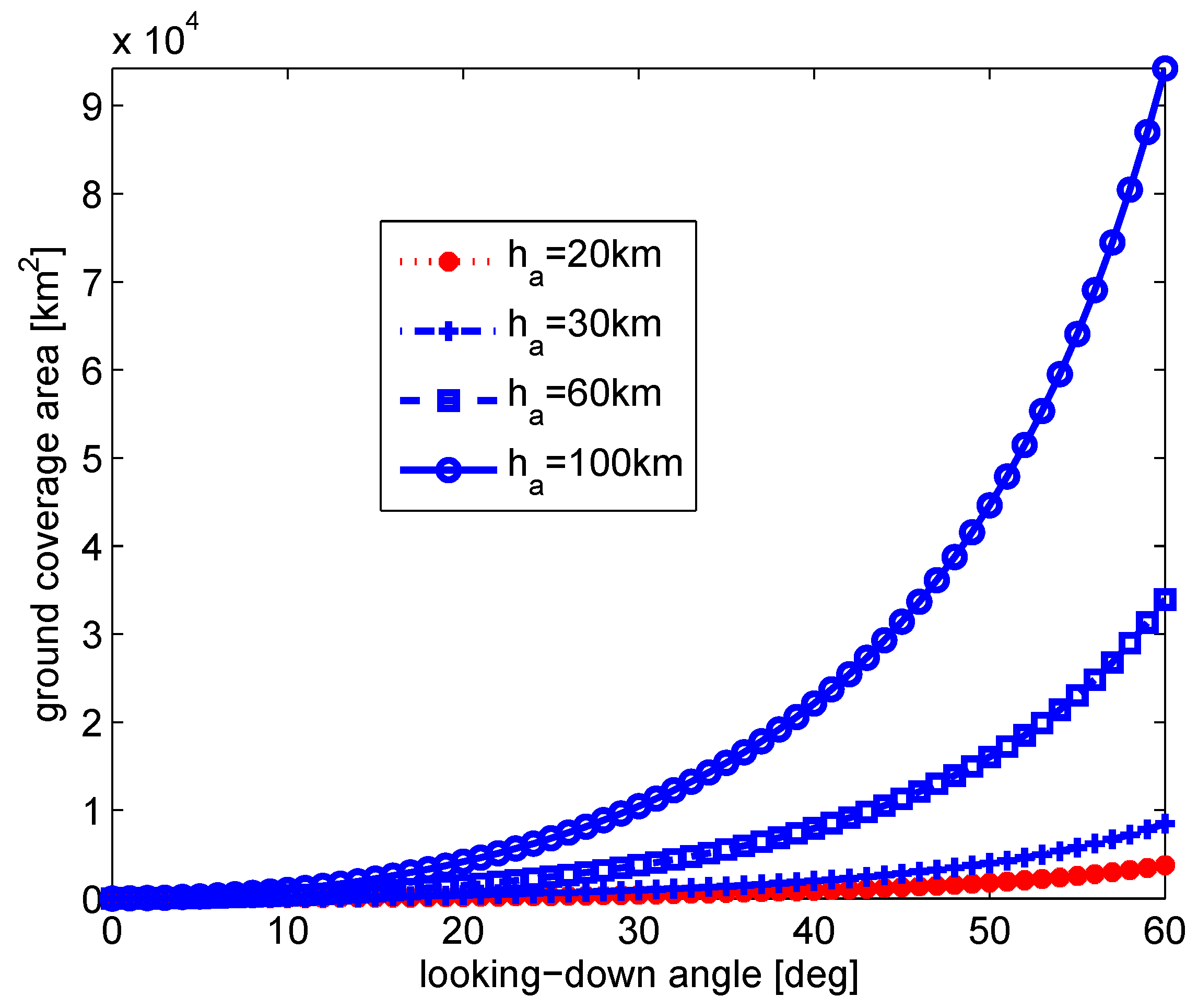
2.4. Relative High Sensitivity and Large Footprint

Near-space platforms are much closer to the targets than their orbital cousins. Distance is critical to receiving low-power signals. From the radar equation [18] we know that the received power attenuates in the square of the distance from the transmitter to the target, while that of an active antenna attenuates in the fourth power of the transmitter distance. Considering a point at nadir, near-space platforms are 10–20 times closer to their targets than a typical 400 km LEO satellite. This distance differential implies that it could detect much weaker signals (10 dB to 13 dB weaker). Moreover, the footprint covered by near-space sensors are also satisfactory. Figure 2 shows the ground coverage area as a function of looking-down angle for different flying altitude.
Figure 2. Ground coverage area as a function of looking-down angle for different flying altitude.
Remotesensing 02 00717 g002
Additionally, being lower than satellites also brings about another advantage to near-space platforms: they fly below the ionosphere. Ionospheric scintillation can have significant effects on radio communication and navigation accuracy. Ionospheric scintillation is very difficult to predict, but it can disrupt satellite significantly. Fortunately, ionospheric scintillation has no impact on near-space sensors.

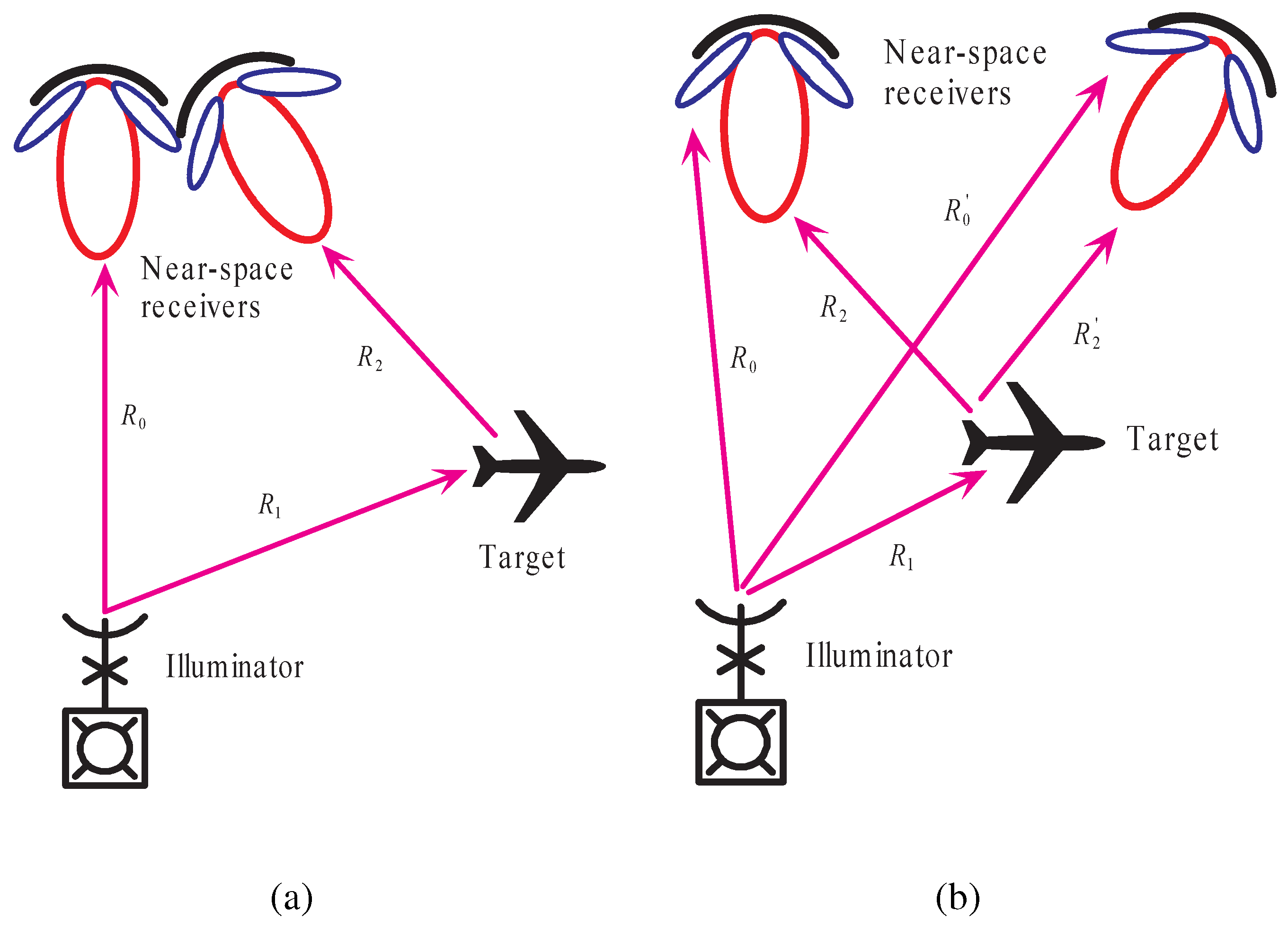
3. Near-Space Passive Radar Remote Sensing

Passive radar is a receiver-only radar that usually dissociates the receiving antenna at a different location from the transmitter [19]. The interest in bistatic radar, particularly synthetic aperture radar (SAR) has rapidly increased in recent years [22,23,24,25,26,27,28]. This is based on the specific advantages of bistatic radar configurations in comparison to monostatic systems like increased information with regard to feature extraction and classification. This could be worthwhile, e.g., for topographic features, surficial deposits, and drainage, to show the relationships that occur between forest, vegetation and soils. Even for objects that show a low RCS in monostatic radar images, one may find distinct bistatic angles to increase their RCS to make these objects visible in the final radar image. At the same time, there has been a resurgence of the interest in passive bistatic radar systems [29,30,31], partly because they do not require fielding expensive transmitters and partly fueled by technology developments in digital signal processors and processing algorithms [32,33].

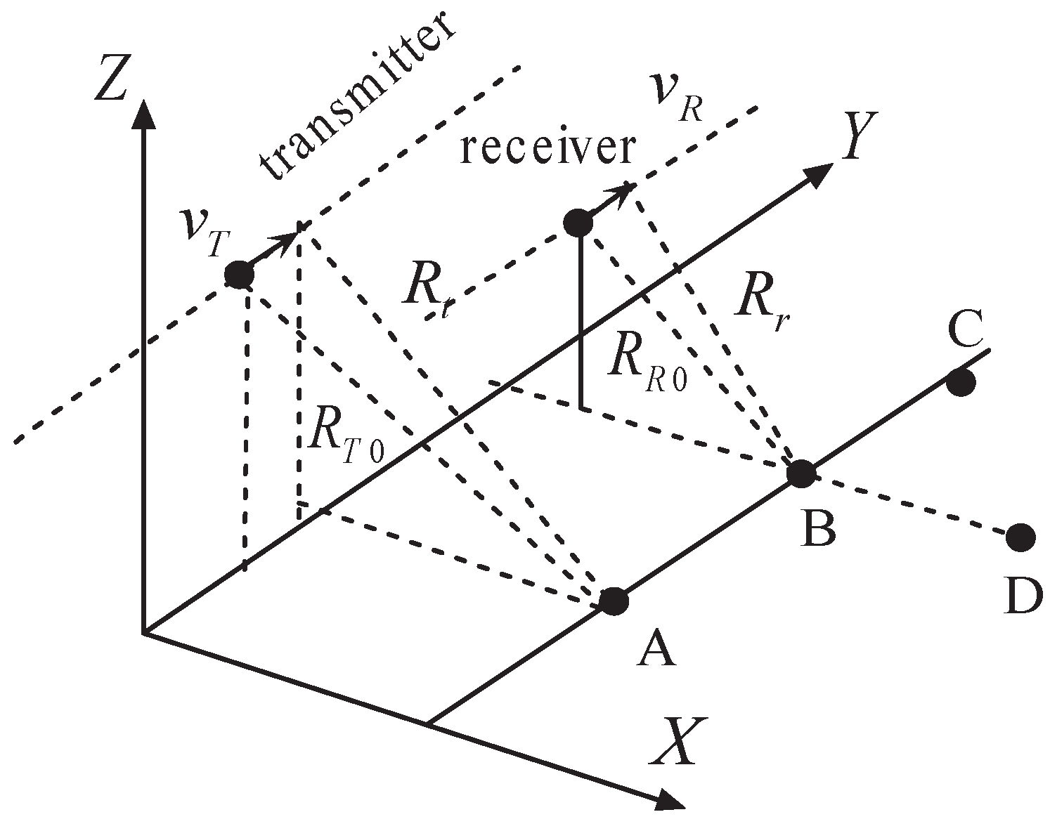
3.1. Radar Configurations

To achieve persistent regional remote sensing, we proposed the concept of near-space platform-based passive radar imaging. This concept involves placing a passive receiver inside a near-space platform and utilizing opportunistic illuminators such as frequency modulation (FM) radio [34], digital television [35], digital broadcasters [36] or spaceborne imaging radars [37]. A promising opportunistic illuminator is global navigation satellite systems (GNSS). Taking global position systems (GPS) as an example, GPS broadcasts a civilian-use signal at 1.57542 GHz, referred to as ‘‘L1’’. Additionally, a second carrier signal for military use is also broadcasted at 1.2276 GHz, referred to as ‘‘L2’’, but civilian reception of this signal requires complicated processing algorithms. Both ‘‘L1’’ and ‘‘L2’’ signals are constantly scattered off earth surface, and are known to contain valuable and varied information on the targets or environment [38,39,40,41,42]. The use of GNSS signals has many advantages such as entire planet coverage, simple transmitter-receiver synchronization, and precise knowledge of the transmitter position information. Although the near-space receiver may be stationary, an aperture synthesis can still be achieved with the motion of the GPS satellite only [43,44]. This configuration provides many specific advantages, like the exploitation of additional information contained in the bistatic reflectivity of targets [45,46], reduced vulnerability in military systems [47], forward-looking SAR imaging [48], and improved detection capability of slowly moving targets [49]. More importantly, this passive bistatic SAR has a particular value for persistent region monitoring. Rather than emitting signals, it relies on opportunistic illuminators to monitor the area of interest without influencing normal communication and broadcast systems.
One attractive configuration is the two-channel receiver configuration, as shown in Figure 3(a). One channel is fixed to collect the direct-path signals, which can be used as the reference signal for matched filtering. The second channel is configured to gather the scattered signals with which the detection of targets is being attempted. Typically, the signals scattered from a target are much weaker than the direct-path signals. Unless the transmit antenna attenuates sufficiently in the direction of the illuminator, the reflected channel will contain more energy from the direct-path signals than from the scattered signals. The use of array antennas is being considered to overcome this problem.
The configuration using two or more near-space receivers located far apart is also feasible. Each using its independent antenna, as shown Figure 3b. In this configuration, each near-space receiver performs its own matched filtering using the received signal, the results of which can then be combined in some manner to provide a single target positioning and imaging. In fact, the configuration using only a single-channel near-space receiver is also feasible. In this case, the received signals would contain energy from both the direct-path signals and the scattered signals. Once they are separated, successful matched filtering can then be performed.
Another promising configuration is digital beamforming on receive [50]. As shown in Figure 4, the satellite antenna footprint exceeds by far the size of the near-space receiver footprint. To prevent the simultaneous data collection area from being restricted by the small receiver footprint, the receiver antenna is split into multiple subapertures. This idea for spaceborne bistatic SAR has been proposed by Krieger and Moreira [22]. In this way, each subaperture signal is separately amplified, down-frequency converted and digitized. The digital signals are then combined in a dedicated processor to form multiple antenna-beams with arbitrary shapes. Digital beamforming on receive also allows for a selective interference suppression. Interferences from nadir and/or direct-path signals can then be suppressed by appropriate null-steering. A further potential is moving target indication (MTI). This becomes possible by a combined spatial and temporal processing of the recorded signals that allows for a directly selective suppression of narrow Doppler frequency bands from stationary clutter [51]. Furthermore, optimum processing schemes for MTI may be derived from the theory of space-time adaptive processing (STAP) [52,53].
Figure 3. Configurations of near-space passive radar system: (a) one receiver with two channels; (b) multiple receivers.
Remotesensing 02 00717 g003
Figure 4. Near-space passive radar with digital beamforming on receive.
Remotesensing 02 00717 g004

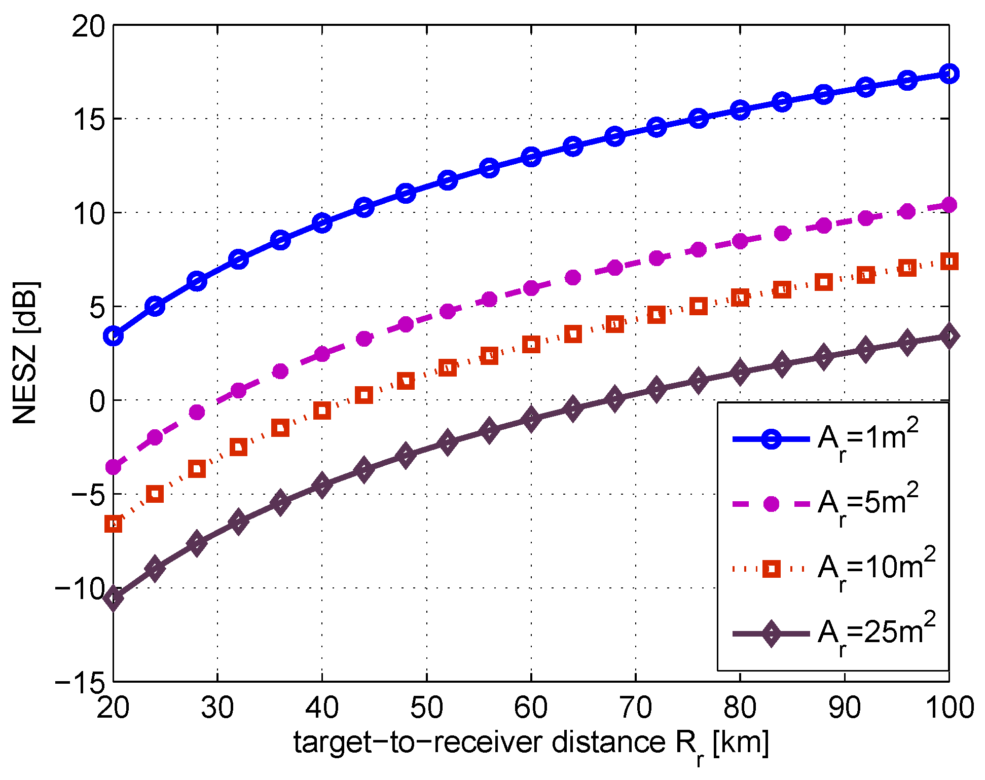
3.2. Power Budget Analysis

Using opportunistic illuminator, particularly GPS satellite as the transmitter for near-space passive radar imaging brings a problem of signal detection because the received signal will be very weak. Thus, power budget analysis is necessary. The power of the target reflection available at the near-space receiver antenna is determined by
P r = P t G t 4 π R t 2 · σ 0 4 π R r 2 · λ 2 G r 4 π
where P t is the transmit power, G t is the transmit antenna gain, R t is the transmitter-to-target distance, R r is the target-to-receiver distance, σ 0 is the target RCS per unit area, λ is the wavelength and G r is the receive antenna gain, respectively. In radar imaging applications, the total data samples are processed coherently to produce a single image resolution cell. The thermal noise samples can be taken as independent from sample to sample within each pulse, and from pulse to pulse.
After coherent range and azimuth compression, the image signal-to-noise ratio (SNR) can be represented by [23]
S N R i m a g e = P t G t 4 π R t 2 · A r σ 0 4 π R r 2 · 1 K T 0 β F n · τ i τ 0 · P R F · R · λ v a · ρ a · η
where P R F is the pulsed repeated frequency (PRF), A r is the antenna area, R s is the distance from the moving carrier that provides the synthetic aperture to the target, the power flux density near the Earth’s surface produced by GPS satellite is assumed to be ( P t G t ) / ( 4 π R t 2 ) = Π 0 3 × 10 - 14 W t / m 2 [43]. The ratio of the compressed signal duration τ 0 and uncompressed signal duration τ i is equivalent to the SNR gain after range compression, which is the correlation between the reflected signal and reference signal. ( P R F · R s · λ ) / ( v a · ρ a ) is the processing gain during the time of the aperture synthesis with P R F , v a and ρ a are the pulse repeated frequency, relative velocity and azimuth resolution cell, respectively. Assuming the receiver bandwidth and transmitting signal bandwidth are matched and η = 0 . 5 , then there is β τ 0 1 . The receiver noise coefficient F n is considered to be 2 d B . Additionally, K and T 0 denote the Boltzmann constant, and system noise temperature, respectively.
As the potential azimuth resolution can be rewritten as
ρ a = λ R s v a T s
where T s is the integration time, we can get [54]
S N R i m a g e = Π 0 A r λ η 4 π F n K T 0 ρ a σ 0 R s v a
A quantity directly related to radar imaging performance is noise equivalent sigma zero (NESZ), which is the mean RCS necessary to produce a S N R i m a g e of unity. NESZ can be interpreted as the smallest target cross section which is detectable by the SAR system against thermal noise. Setting S N R i m a g e = 1 Equation (4) gives
N E S Z = 4 π F n K T 0 ρ a R s v a Π 0 A r λ η .
In a like manner as [43], assuming a typical system with the following parameters: σ 0 = 20 2 , T s = 1 , 000 s , T 0 = 300 , η = 0 . 5 , and F n = 2 d B , the calculated SNR can be illustrated as in Figure 5. Here the SNR is favorable owing to an essentially long integration time. Although this SNR can be further improved by using non-coherent integration of the signals from more than one receiver channel, weak signal detection and processing is a technical challenge for near-space passive radars.
Figure 5. Calculated NESZ with a function of target-to-receiver distance.
Remotesensing 02 00717 g005

3.3. Potential Applications

The near-space passive radar provides many promising potentials due to the superiorities of persistent region coverage, robust survivability, bistatic observation and low cost. Henderson et al. [55] have presented a status report on the applications of SAR for detecting human settlement, estimating population, assessing the impact of human activities on physical environment, mapping urban land use patterns and change, and interpreting socioeconomic condition. Certainly, all of these applications are also possible for near-space passive radar. Moreover, near-space passive radar can provide the following additional potentials:
One promising potential application is homeland security. To protect civilian population, mass transit, civil aviation and critical infrastructure from terrorist attacks employing explosive devices, significant improvement in our capability to detect and mitigate explosive threats are required, so that we can efficiently combat these threats without impacting normal day-to-day human activities and commerce activities. To reach this aim, radar has long been used in a variety of military and civilian applications and has been an essential component of current defensive systems. Presently, many countries have civil aviation radar networks. Such radar networks are specifically designed to ensure early alert against potential hostile targets. However, the range and nature of potential threat targets are becoming even more diverse. The tragic event on 11 September 2001 is just one example. Others might include missile attack and unmanned aerial vehicles (UAV). This means that the source of attack can be in a much wider variety of new and different forms, and cannot be well dealt with current radar systems. Fortunately, it appears that passive radar using opportunistic illuminators can provide a potential solution to these problems. More importantly, synthetic aperture (i.e., SAR) can be obtained for the near-space passive radar. In this way, it can not only detect moving targets but also monitor regional scene persistently.
Another advantage is that, rather than emitting signals, this passive imaging system relies on opportunistic transmitters to image potential targets or scene. This allows the receiver to operate without emitting signals. This is particularly attractive for homeland security applications, because it is desirable for such sensor to also serve other purposes like traffic monitoring and weather prediction. In addition, the fact that they require no dedicated transmitters also means significant cost savings.
Another promising potential application is persistent region environment monitoring. A good example is disaster monitoring. In recent years, the frequency of natural disasters has shown rapid increase [56]. Examples of this trend are related to floods, earthquakes, tsunamis, hurricanes, and forest fires [57]. The tsunami that killed thousands of people in the coastal areas of India, Indonesia, Thailand and Sri Lanka has brought the awareness that we cannot no longer take natural disasters as something inevitable or unavoidable and remain as helpless observers. Methods and strategies along with effective devices have to be developed to predict and fight natural disasters. To reach this aim, immediately after that tsunami, natural disaster monitoring has received much recognition [58], but there is still lack of feasible and practicable solution. Near-space passive radar remote sensing does indeed seem to be a promising solution. Moreover, since natural disasters are relatively infrequent events, it is desirable for such sensor to serve also as other purpose like weather and ocean monitoring (floods, sea-swells, cyclones) as well as surveillance, reconnaissance, and traffic monitoring [59,60].

3.4. Technical Challenges

Near-space passive radar shows much promise for remote sensing applications, but several challenges must be overcome. The most important one, besides synchronization compensation (including phase [61,62], spatial [63,64] and time [65] synchronization) is image formation algorithm. In near-space passive bistatic SAR system, the illuminator (take also GPS satellite as an example) follows a rectilinear trajectory, while the receiver follows also a rectilinear trajectory but with a different velocity.
Consider the geometry depicted in Figure 6, the instantaneous slant range of a given point target is
R ( τ ) = R T 0 2 + ( v T τ ) 2 + R R 0 2 + ( v R τ ) 2
where R T 0 is the closest slant range to the transmitter, R R 0 is the closest slant range to the receiver, v T is the transmitter velocity, v R is the receiver velocity, τ is the slow time in azimuth, respectively. It is noticed that the range history of a given point target does not depend any more only on the zero-Doppler distance and the relative distance from the target to the transmitter, but also on the absolute distance to the receiver. The instantaneous Doppler frequency is
f d ( τ ) = - 1 λ d R ( τ ) d τ = - 1 λ ( v T 2 τ R T 0 2 + ( v T τ ) 2 + v R 2 τ R R 0 2 + ( v R τ ) 2 )
The corresponding Doppler chirp rate can be derived as
k d ( τ ) = - 1 λ d 2 R ( τ ) d 2 τ - 1 λ [ v T 2 R T 0 cos ( v T τ R T 0 ) + v R 2 R R 0 cos ( v R τ R R 0 ) ]
Figure 6. System geometry of ear-space passive bistatic SAR.
Remotesensing 02 00717 g006
As near-space passive SAR is an azimuth-variable bistatic SAR, from Figure 7 we find that there is a range ambiguity that does not exist in monostatic or azimuth-invariable bistatic cases. Two or more point targets located at different positions can have the same range delay at zero-Doppler but will have different range histories. Further analysis shows that its Doppler chirp rate will be azimuth variable, as shown in Figure 8. Note that the simulation parameters used in this plot are: transmitter velocity and altitude are 3,870 m/s and 20,183 km, near-space receiver velocity and altitude are 5 m/s and 20 km, respectively. The results show that there is a technical challenge towards developing efficient focusing algorithms. This situation will get more complicated for unflat digital earth model (DEM) topography. In monostatic or azimuth-invariable bistatic SAR systems, scene topography is ignored in image formation processing because the measured range delay is related with the double target distance and the observed range curvature; Hence, topography is only used to project the compressed image, which is in slant range to the ground range. However, for near-space passive SAR, because of its azimuth-variant configuration, it is a mandatory to know both transmitter-to-target distance and target-to-receiver distance to properly focus its raw data.
Figure 7. Targets with the same range delay at zero-Doppler but will have different range histories.
Remotesensing 02 00717 g007
Figure 8. The azimuth-variable characteristics of Doppler chirp rate for near-space passive bistatic SAR.
Remotesensing 02 00717 g008
In this case, efficient monostatic SAR algorithms such as Chirp scaling [66] and ω-K [67], may be unsuitable to accurately focus the collected data due to topography dependence of the impulse response. Therefore, some new efficient image formation algorithm should be found for this near-space SAR configuration. Possible solutions are back-projection algorithm [68] and nonlinear chirp scaling algorithm [69].

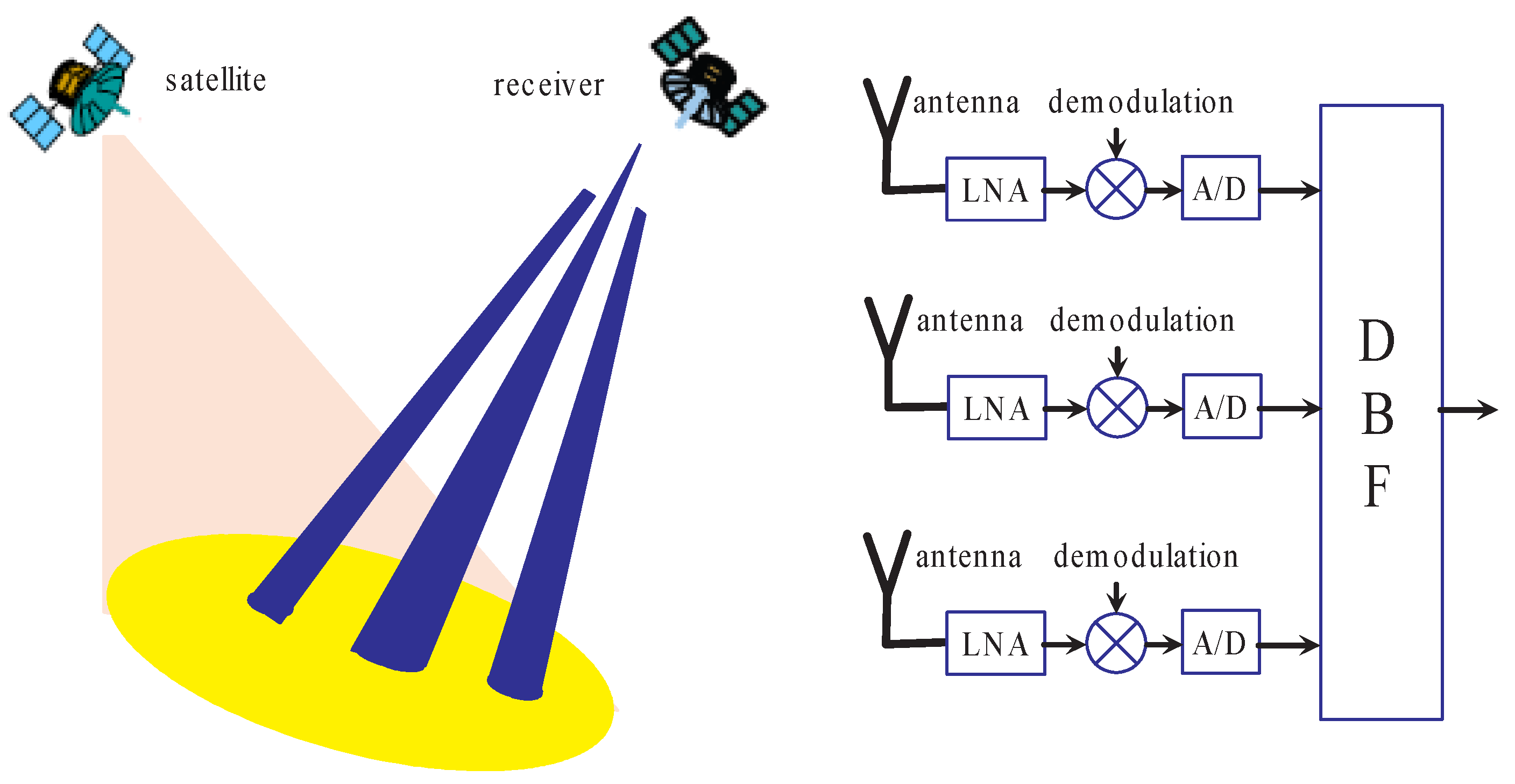
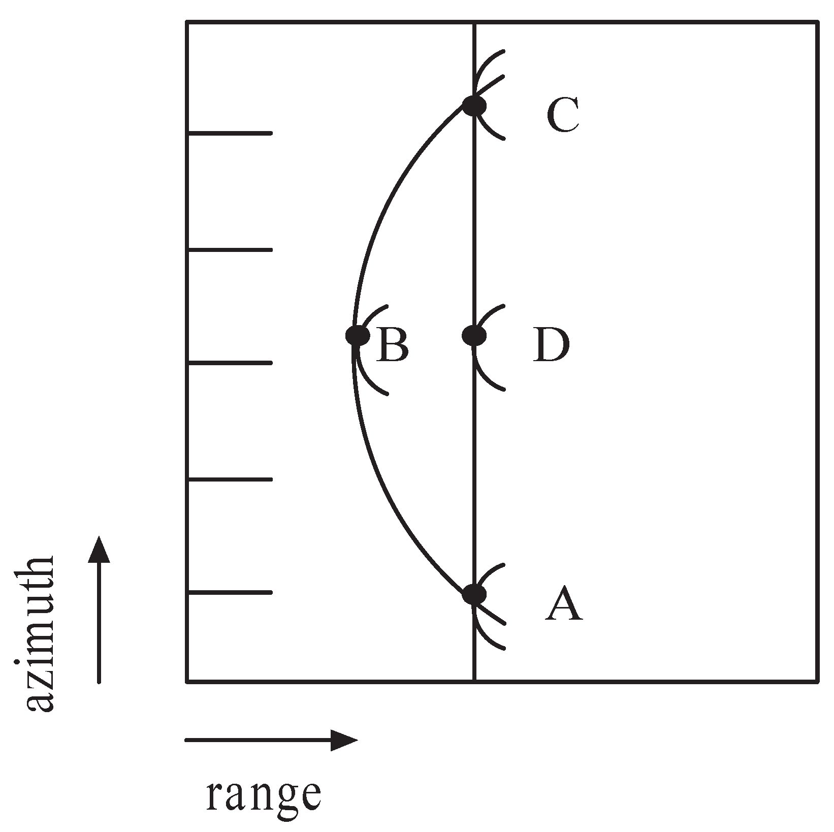
4. Near-Space High-Resolution and Wide-Swath Imaging

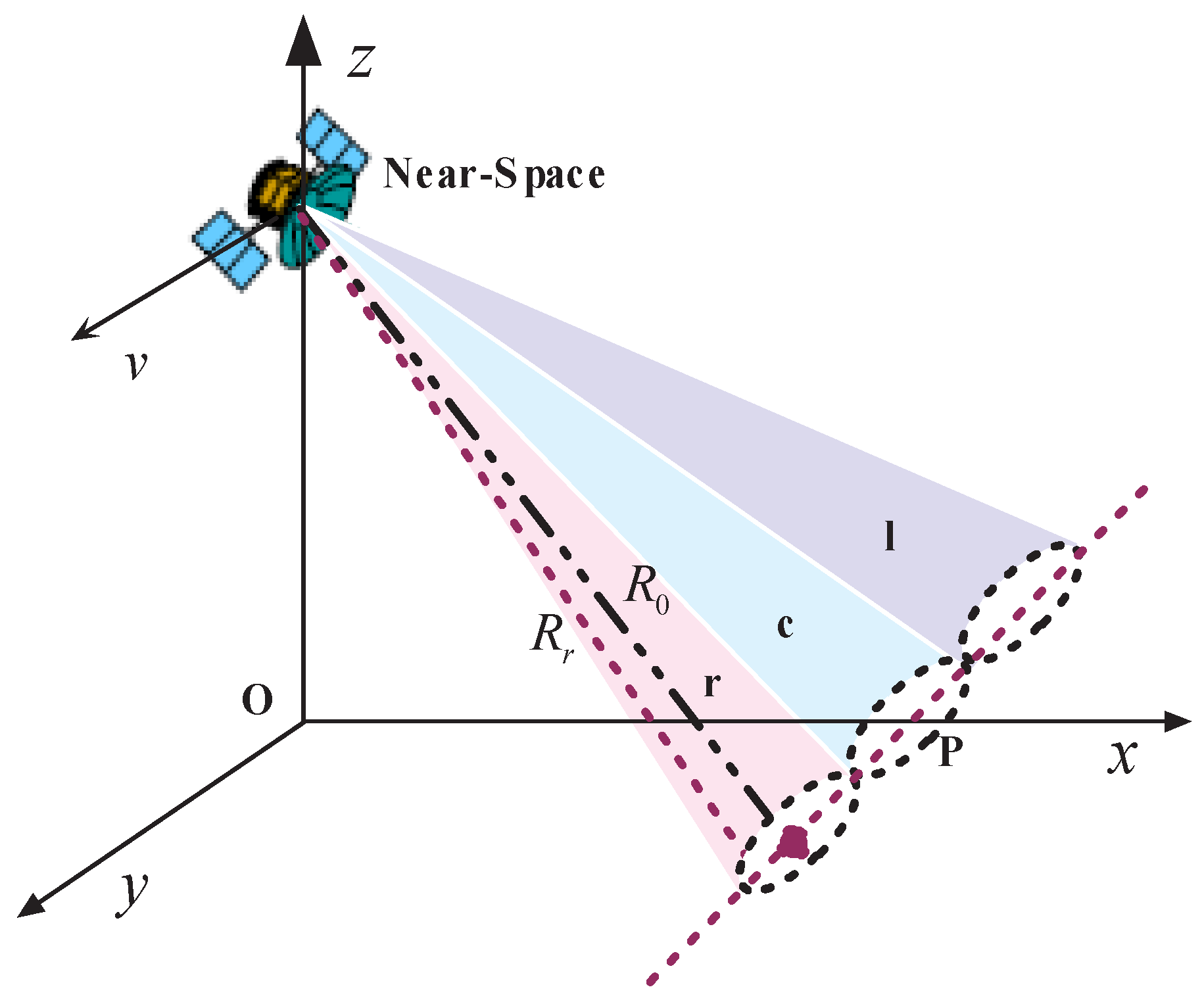
4.1. System Configuration

Future SAR will be required to produce high resolution imagery over a wide surveillance area. However, it is a contradiction to obtain both unambiguous high azimuth and wide swath. The actual achievable resolution and swath width is subject to a number of restrictions imposed by various operating factors. The details can be found in [70]. A basic limitation is the minimum antenna area constraint, which can be represented by [71]
A r = W a L a 4 v a λ R c tan ( θ ) c o
where W a and L a are the antenna width and length respectively, v a is velocity of the SAR platform, R c is the slant range from radar to the midswath, θ is the incidence angle, and c o is the speed of light. This requirement arises because the illuminated ground area must be restricted, so that the radar does not receive ambiguous echoes in range or/and azimuth (Doppler). In this respect, a high operating operational PRF is desirable to suppress azimuth ambiguity. But the magnitude of the operating PRF is limited by range ambiguity.
By rearranging the terms in Equation (9) with the expression of SAR azimuth resolution, the ratio of swath width ( W s ) to azimuth resolution ( ρ a ) is found to be
W s ρ a < c o 2 v a sin ( θ )
From Equation (10) we see that the ratio between azimuth resolution and swath width depends on platform velocity and incidence angle. Generally, c o / v a is nearly constant at 20,000 for LEO satellites and typically in the range of 300,000–750,000 for airborne systems. As near-space SAR can fly at a velocity from 0 m/s to 1,500 m/s, the c o / v a will be greater than 100,000. Therefore, compared to spacebore SAR and airborne SAR, near-space provides an optimal solution to simultaneous high-resolution and wide-swath SAR imaging. Nevertheless, to further alleviate the requirements on the minimum antenna area, applying some additional techniques is necessary. Several techniques have been suggested [72,73], but the use of a quad-element array will become difficult for high-resolution applications because synthesizing a number of apertures is required.
Figure 9. Near-space HRWS SAR with three sub-apertures.
Remotesensing 02 00717 g009
If multiple sub-apertures (e.g., N) in azimuth (see Figure 9) is employed, the area of each sub-aperture antenna is then restricted by
A r s 4 v s λ R c tan ( θ ) c 0 · 1 N .
Clearly the minimum area for each sub-aperture antenna can be N-times smaller than that of a monostatic SAR. In this case, the displaced phase centre technique [73] can then be used to gain additional samples, which enables an efficient suppression of azimuth ambiguities, i.e., the multiple sub-apertures in azimuth allows for the division of a broad Doppler spectrum into multiple narrow-band subspectra with different Doppler centroids. A coherent combination of the subspectra will then yield a broad Doppler spectrum for high azimuth resolution. A distinct channel is associated with each sub-aperture signal which is separately amplified, down-converted and digitized. In this way, the acquired data are split according to the azimuth angular position, i.e., the instantaneous Doppler centre frequency. As a result, while given knowledge of the relative squint angles of each sub-aperture (and hence the Doppler centre frequency for each sub-aperture) and assuming suitable isolation between the beams, each channel can be sampled at the Nyquist rate appropriate to the bandwidth covered by each narrow sub-aperture, instead of that covered by the full aperture.
The conclusion is unambiguous range and swath width can be further increased by using a near-space SAR with multiple antennas in azimuth. But, since a need for multiple antennas is the drawback for interbeam suppression, some additional means of interbeam suppression should be applied. One possible technique is the use of waveform diversity to provide some cross-cancellation of data in different channels.

4.2. Potentials and Challenges

It is well known that imaging radar applications include a wide range of sometimes conflicting requirements on coverage, revisit and access time. For example, security applications typically require a very high resolution image of a small area to be available within a very short time in the order of hours. On the other hand, agricultural applications require a relative low resolution image of a large area within a periodically repeated cycle. Near-space HRWS SAR can meet these requirements with adjustable resolution and coverage. This allows future imaging radar systems to simultaneously provide different end-users with high quality information products depending on their need. Particularly, near-space HRWS SAR is of great interest in evaluating natural disaster damage [74,75]. An example is the catastrophic earthquake occurred in Wenchuan (Sichuan province, China) on 12 May 2008, which killed thousands of people. In this case, near-space HRWS SAR can play a particularly important role in detecting human settlements, evaluating earthquake damages, and monitoring environment changes because of its fast revisiting capability besides relative high resolution and wide swath imaging.
Another potential application is ocean remote sensing. A good example is tsunami detection. Tsunami can be originated by earthquake, submarine landslides, volcanic eruptions or a combination of these factors. It has been proven that there is a link between tsunami wave amplitude and its microwave RCS, and significant (a few dB) variations of the RCS synchronous with the sea level anomaly has been found both at C and Ku band in the geophysical data record of the altimetry satellite Jason-1 [76,77]. From the view of microwave active remote sensing, the detectable oceanographic features of a tsunami wave can be summarized as [12]: (1) tsunami wave height, (2) tsunami orbital velocities, (3) tsunami-induced RCS modulations. It has been proved the capability of microwave radars to detect internal waves [78], which are generally triggered by tides. Along with tides, tsunamis are shallow water waves and have the potential to trigger internal waves. As such, tsunami-induced RCS modulations can be used to predict future tsunami. This involves not only detection but also an estimate of the tsunami magnitude. Due to its fast revisiting frequency, relative simultaneous high resolution and wide swath, near-space HRWS SAR does indeed seem to be the obvious solution to these remote sensing applications.
However, for optimum near-space HRWS SAR imaging performance the relation between sensor velocity v a and the along-track offsets Δ x of the N sub-apertures has to result in equally spaced effective phase centers, thus leading to a uniform sampling of the received signal. This requires the following relation [79]
P R F o p t = 2 v a N Δ x
If a non-optimum PRF is chosen, the gathered samples are spaced non-uniformly. This requires a further processing step after down-conversion and quantization of the multi-aperture azimuth signal before conventional monostatic focusing algorithm can be applied. The purpose of the azimuth processing is to combine the N channels, each of bandwidth N · P R F but sub-sampled with P R F , to obtain a signal effectively sampled with N · P R F = P R F e f f . Thus the Nyquist criterion is fulfilled in average after the processing, which yields an output signal that is free of aliasing.
Consider again Figure 7 we may view it as a conventional SAR (the central sub-aperture), operating with a PRF one third of that required to adequately sample its beamwidth, together with additional two sub-apertures, on both sides of the central one. This basic idea is that the additional samples obtained by the outer sub-aperture will fill in the gaps in a target’s azimuth phase history with a low operating PRF. The ambiguous Doppler spectrum can be recovered unambiguously by applying a system of reconstruction filters. Some reconstruction algorithms have been proposed by other authors, e.g., [80]. In this paper, another simple reconstruction algorithm is derived. A block diagram for the reconstruction from the three sub-aperture signals is shown in Figure 8 (left). This algorithm is based on considering the data acquisition in a multi-aperture near-space SAR as a linear system with multiple channels, each can be described by a linear filter. From the sampling theorem, we know that the sampled signal spectrum X s ( f ) is the sum of the unsampled signal spectrum, X 0 ( f ) , that is repeated every f s Hz with f s the sampling frequency(samples/sec.). That is:
X s ( f ) = f s n = - X 0 ( f - n f s )
If f s 2 B d , the replicated spectra do not overlap, and the original spectrum can be regenerated by chopping X s ( f ) off above f s / 2 . Thus, X 0 ( f ) can be reproduced from X s ( f ) through an ideal low-pass filter that has a cutoff frequency of f s / 2 . In this way, subsequent data processing involves interpolating the data from each channel. We then have:
y s ( n ) = x s ( n N 0 )
where N 0 is the interpolation scale. Correspondingly, its spectrum is represented by
Y s ( f ) = n = - y s ( n ) e - j 2 π f n = X s ( N 0 f )
Then, the linear filters can be derived as
H k ( f ) = N 0
where f c k is the corresponding Doppler centroid.
Finally, the filtered signals can then be combined coherently, as shown in Figure 10 (right). In this way, the capability of ambiguity suppression allows for improved resolution and an enlarged swath. Note that this technique is also useful for ambiguity suppression in a distributed near-space SAR with multiple transmitters or/and receivers. However, any cross-track separation of the receivers will introduce additional phase in the received signals, which has to be compensated. Moreover, the joint processing these data will then lead to a nonlinear combination of cross-track interferometry [81].
Figure 10. Azimuthal spectra synthesis for multichannel subsampling in case of three channels.
Remotesensing 02 00717 g010

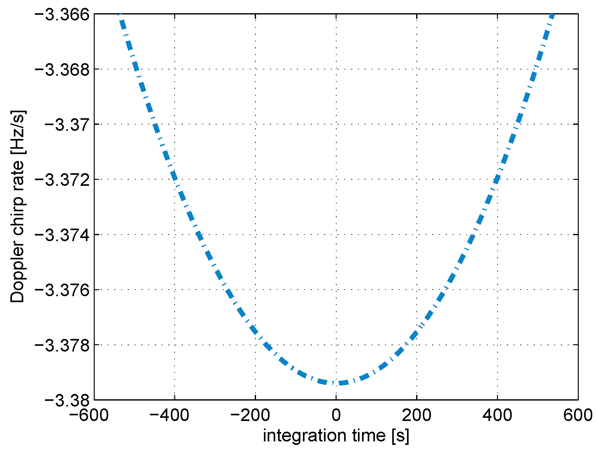
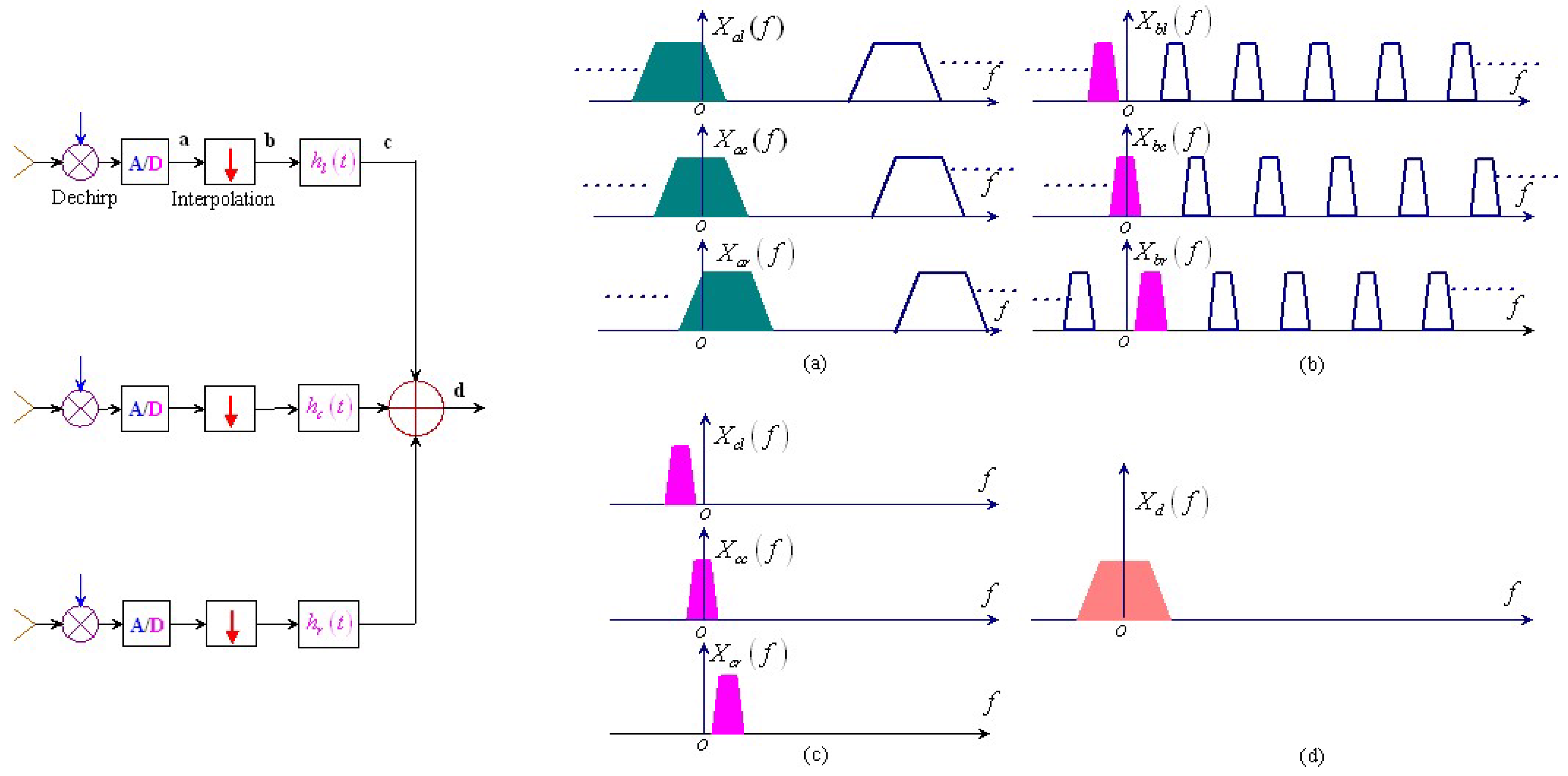
5. Motion Compensation

Strict relative position or altitude is essential for the near-space radars described above. As a matter of fact, problems arise due to the presence of atmospheric turbulence, which introduce platform trajectory deviations from normal position or altitude (roll, pitch, and yaw angles) [82,83]. Hence, motion compensation is required. In current radar systems, GPS and inertial navigation system (INS) are usually deployed for this task. However, for near-space radars, motion measurement facilities may not be reachable because of their limited load capabilities, so some new efficient motion compensation techniques should be developed.
Active transponder, which was used for calibrating high-resolution imaging radars [84,85], can be used for motion compensation. This transponder retransmits the received signal with artificial Doppler frequencies to the receiver. If the artificial Doppler drift is chosen to be larger than the Doppler bandwidth of the raw data, the transponder signals can be separated during subsequent signal processing, allowing to extract the platform’s motion information without clutter interference. In this way, successful motion compensation may be achieved.
As shown in Figure 11, the active transponder consists of a low-noise amplifier followed by a bandpass filter. A voltage controlled attenuator (VCA) is used to modulate the received signal in a manner that the retransmitted signal will show two additional Doppler frequencies. Afterwards the signal will be amplified to an appropriate level and retransmitted towards the receiver. Hence this transponder can be seen as an amplitude modulator
S c ( t ) = [ γ + β cos ( 2 π f m t + φ m ) ] · s 0 ( t ) = β 2 e j ( - 2 π f m ) t - j φ m · s 0 ( t ) + γ · s 0 ( t ) + β 2 e j ( 2 π f m ) t + j φ m · s 0 ( t )
where f m is the transponder modulation frequency, φ m is the starting phase and s 0 ( t ) is the transmitted signal. We can notice that, the retransmitted signal will show the original signal and two additional Doppler frequencies, one positively and one negatively shifted. Assuming the transmitted signal is one chirp signal, the spectrum of retransmitted radar signal modulated by the transponder is shown in Figure 12. This allows to extract the motion compensation information without clutter interferences.
Figure 11. Transponder based motion compensation.
Remotesensing 02 00717 g011
Figure 12. Spectrum of retransmitted signal modulated by the transponder.
Remotesensing 02 00717 g012
The corresponding near-space sensor received signal can be represented by
S R ( t ) = S s ( t ) + [ γ + β cos ( 2 π f m t + φ m ) ] · S m ( t )
where S s ( t ) and S m ( t ) denote the unmodulated part and the echo of the transponder without the amplitude modulation, respectively. Afterwards, S m ( f ) can be transformed back into its time-domain representation s m ( t ) using an inverse Fourier transform. Evaluating the phase of s m ( t ) leads to a motion compensation solution [86]. In this way, placement of several transponders in a planned imaging region can help to get motion information about the near-space platform and enable subsequent motion compensation. Note that the range histories to the visible transponders can be determined very accurately, particularly because of the high SNR performance. Additionally, we think raw data-based autofocus algorithm may be a good a choice for near-space radar motion compensation [83,87], but further investigations are required.

6. Conclusions

Near-space offers a significant new opportunity for radar remote sensing techniques for several reasons. Firstly, it supports uniquely effective and economical operations. Secondly, it enables a new class of especially useful intelligence data. Thirdly, it provides a crucial corridor for prompt regional strike. Inspired by the promise of near-space, this paper reviews the applications of near-space in microwave radar remote sensing. Several near-space radar configurations including passive radar and high-resolution and wide-swath SAR are described, along with the corresponding potential applications, technical challenges and possible solutions. It is shown that the novel use of cost-effective near-space radar can provide the promising solutions that were thought to be out of reach for remote sensing scientists and customers. We do not advocate eliminating satellites or airplanes; however, in many circumstances near-space platforms are indeed the best choice for providing some specific remote sensing applications. It is evident that there are large niches where near-space platforms perform much better than satellite and airplane. Once we understand that it is effects instead of the platform from which the effects are delivered, near-space makes much sense for the remote sensing applications described. Although exploring the potentials of near-space in microwave radar remote sensing applications require significant work on many fronts, we are indeed convinced the effort will be worth it.

Acknowledgements

This work was supported in part by the Specialized Fund for the Doctoral Program of Higher Education for New Teachers under the contract number 200806141101 and the Open Fund of the Institute of Plateau Meteorology(IPM), China Meteorological Administration(CMA) under Contract number LPM2008015.

References and Notes

  1. Meyer, F.; Hinz, S.; Laika, A.; Weihing, D.; Bamler, R. Performance analysis of the TerraSAR-X traffic monitoring concept. ISPRS J. Photogramm. Remote Sens. 2006, 61, 225–242. [Google Scholar] [CrossRef]
  2. Solberg, A.H.S.; Brekke, C.; Husoy, P.O. Oil spill detection in Radarsat and Envisat SAR images. IEEE Trans. Geosci. Remote Sens. 2007, 45, 746–755. [Google Scholar] [CrossRef]
  3. Trouve, E.; Vasile, G.; Gay, M. Combining airborne photographs and spaceborne SAR data to monitor temperate ciers: potentials and limits. IEEE Trans. Geosci. Remote Sens. 2007, 45, 905–924. [Google Scholar] [CrossRef]
  4. Massonnet, D. Capabilities and limitations of the interferometric cartwheel. IEEE Trans. Geosci. Remote Sens. 2001, 39, 506–520. [Google Scholar] [CrossRef]
  5. Wang, W.Q.; Cai, J.Y. A technique for jamming bi- and multistatic SAR systems. IEEE Geosci. Remote Sens. Lett. 2007, 4, 80–82. [Google Scholar] [CrossRef]
  6. Wang, W.Q. Application of near-space passive radar for homeland security. Sens. Imag. Int. J. 2007, 8, 39–52. [Google Scholar] [CrossRef]
  7. Sullivan, I.W.T.; Knowles, S.T. The near-space unwanted RF environment as observed using VHF lunar reflections. IEEE Trans. Electromag. Compat. 1985, 27, 115–118. [Google Scholar] [CrossRef]
  8. Zheng, B.; Ren, Q.H.; Liu, Y.J.; Chu, Z.Y.; Zhao, F. Characteristic and simulation of the near space communication channel. In Proceedings of International Symposium on Microwave, Antenna, Propagation, EMC Technologies for Wireless Communication,, Huangshan, China; 2007; pp. 769–773. [Google Scholar]
  9. Allen, E.H. The case for near-space. Aerosp. Am. 2006, 22, 31–34. [Google Scholar]
  10. Marcel, M.J.; Baker, J. Interdisciplinary design of a near space vehicle. In Proceedings of Southeast Conference, Richmon, VA, USA, 2007; pp. 421–426.
  11. Guan, M.X.; Guo, Q.; Li, L. A novel access protocol for communication system in near space. In Proceedings of International Conference on Wireless Communications, Networking and Mobile Computing, Shanghai, China, 2007; pp. 1849–1852.
  12. Galletti, M.; Krieger, G.; Thomas, B.; Marquart, M.; Johannes, S.S. Concept design of a near-space radar for tsunami detection. In Proceedings of IEEE International Geoscience and Remote Sensing Symposium, Barcelona, Spain, 2007; pp. 34–37.
  13. Wang, W.Q.; Cai, J.Y.; Peng, Q.C. Near-space SAR: a revolutionizing remote sensing mission. In Proceedings of Asia-Pacific Synthetic Aperture Radar Conference, Huangshan, China, 2007; pp. 127–131.
  14. Tomme, E.B. Balloons in today’s military? an introduction to the near-space concept. Air Space. J. 2005, 19, 39–50. [Google Scholar]
  15. Kuo, W.M.L.; Krithivasan, R.; Li, X.; Lu, Y.; Cressler, J.D.; Gustat, H.; Heinemann, B. A low-power X-band SiGe HBT low-noise amplifier for near-space radar applications. IEEE Microw. Wirel. Compon. Lett. 2006, 16, 520–522. [Google Scholar] [CrossRef]
  16. Pulinets, S.A. Space technologies for short-term earthquake warning. Adv. Space Res. 2006, 37, 643–652. [Google Scholar] [CrossRef]
  17. Tomme, E.B. The paradigm shift to effects-based space: near-space as a combat space effects enabler. Available online: http://www.airpower.au.af.mil (accessed on March 2008).
  18. Willis, N.J. Bistatic Radar; SciTech Publishing Inc.: Raleigh, NC, USA, 1995. [Google Scholar]
  19. Tan, D.K.P.; Sun, H.; Lu, Y.; Lesturgie, M.; Chen, H.L. Passive radar using global system for mobile communication signal: theory, implementation and measurements. IEE Proc. Radar Sonar Navig. 2005, 152, 116–123. [Google Scholar] [CrossRef]
  20. Howland, P.E. Passive radar systems. IEE Proc. Radar Sonar Navig. 2005, 152, 105–106. [Google Scholar] [CrossRef]
  21. Griffiths, H.D.; Baker, C.J. Passive coherent location radar systems. part 1: performance prediction. IEE Proc. Radar Sonar Navig. 2005, 152, 153–159. [Google Scholar] [CrossRef]
  22. Krieger, G.; Moreira, A. Spaceborne bi- and multistatic SAR: potential and challenges. IEE Proc. Radar Sonar Navig. 2006, 153, 184–198. [Google Scholar] [CrossRef] [Green Version]
  23. Cherniakov, M. Bistatic Radar: Principles and Practice; John Wiley & Sons: Chichester, England, UK, 2007. [Google Scholar]
  24. Cherniakov, M. Bistatic Radar: Emerging Technology; John Wiley & Sons: Chichester, England, UK, 2008. [Google Scholar]
  25. Wang, W.Q. Approach of adaptive synchronization for bistatic SAR real-time imaging. IEEE Trans. Geosci. Remote Sens. 2007, 45, 2695–2700. [Google Scholar] [CrossRef]
  26. Walterscheid, I.; Brenner, A.R.; Ender, J.H.G. Results on bistatic synthetic aperture radar. Electron. Lett. 2004, 40, 1224–1225. [Google Scholar] [CrossRef]
  27. Mishra, A.K.; Mulgrew, B. Bistatic SAR ATR. IET Radar Sonar Navig. 2007, 1, 459–469. [Google Scholar] [CrossRef]
  28. Martorella, M.; Palmer, J.; Homer, J.; Littleton, B.; Longstaff, I.D. On bistatic inverse synthetic aperture radar. IEEE Trans. Aerosp. Electron. Syst. 2007, 43, 1125–1134. [Google Scholar] [CrossRef]
  29. Cetin, M.; Lanterman, A.D. Region-enhanced passive radar imaging. IEE Proc. Radar Sonar Navig. 2005, 152, 185–194. [Google Scholar] [CrossRef] [Green Version]
  30. Li, G.; Xu, J.; Peng, N.Y.; Xia, X.G. Bistatic linear antenna array SAR for moving target detection, location, and imaging with two passive airborne radars. IEEE Trans. Geosci. Remote Sens. 2007, 45, 554–565. [Google Scholar] [CrossRef]
  31. Thomas, J.M.; Griffiths, H.D.; Baker, C.J. Ambiguity function analysis of digital radio mondiale signals for hf passive bistatic radar. Electron. Lett. 2007, 42, 1482–1483. [Google Scholar] [CrossRef]
  32. Morabito, A.N.; Meyer, M.G.; Sahr, J.D. Improved computational performance for distributed passive radar processing through channelised data. IEE Proc. Radar Sonar Navig. 2005, 152, 179–184. [Google Scholar] [CrossRef]
  33. Himed, B.; Soumekh, M. Synthetic aperture radar–moving target indicator processing of multi-channel airborne radar measurement data. IEE Proc. Radar Sonar Navig. 2006, 153, 532–543. [Google Scholar] [CrossRef]
  34. Howland, P.E.; Maksimiuk, D.; Reitsma, G. FM radio based bistatic radar. IEE Proc. Radar Sonar Navig. 2005, 152, 107–115. [Google Scholar] [CrossRef]
  35. Saini, R.; Cherniakov, M. DTV signal ambiguity function analysis for radar application. IEE Proc. Radar Sonar Navig. 2005, 152, 133–142. [Google Scholar] [CrossRef]
  36. Poullin, D. Passive detection using digital broadcasters (DAB, DVB) with COFDM modulation. IEE Proc. Radar Sonar Navig. 2005, 152, 143–152. [Google Scholar] [CrossRef]
  37. Antoniou, M.; Saini, R.; Cherniakov, M. Results of a space-surface bistatic SAR image formation algorithm. IEEE Trans. Geosci. Remote Sens. 2005, 45, 3359–3371. [Google Scholar] [CrossRef]
  38. Zuffada, C.; Zavorotny, V. Coherence time and statistical properties of the GPS signal scattered off the ocean surface and their impact on the accuracy of remote sensing of sea surface topography and winds. In Proceedings of IEEE Geoscience and Remote Sensing Symposium, Sydney, NSW, 2001; pp. 3332–3334.
  39. Gleason, S. Fading statistics of bistatically scattered GPS signals detected from ocean and land in low earth orbit. In Proceedings of IEEE Geoscience and Remote Sensing Symposium, Barcelona, Spain, 2007; pp. 5097–5100.
  40. Coatanhay, A.; Khenchaf, A. Model of GPS signal from the ocean based on an electromagnetic scattering theory: a two scale model (TSM) approach. In Proceedings of IEEE Geoscience and Remote Sensing Symposium, Seoul, Korea, 2005; pp. 3200–3203.
  41. Zavorotny, V.Z.; Voronovich, G. Scattering of GPS signals from the ocean with wind remote sensing application. IEEE Trans. Geosci. Remote Sens. 2000, 38, 951–964. [Google Scholar] [CrossRef]
  42. Zuffada, C.; Fung, A.; Parker, J.; Okolocanyi, M.; Huang, E. Polarization properties of the GPS signal scattered off a wind-driven ocean. IEEE Trans. Antenna Propag. 2004, 52, 172–188. [Google Scholar] [CrossRef]
  43. He, X.; Cherniakov, M.; Zeng, T. Signal detectability in SS-BSAR with GNSS non-cooperative transmitter. IEE Proc. Radar Sonar Navig. 2005, 152, 124–132. [Google Scholar] [CrossRef]
  44. He, X.; Zeng, T.; Cherniakov, M. Interference level evaluation in SS-BSAR with GNSS non-cooperative transmitter. IEE Electron. Lett. 2004, 40, 1222–1223. [Google Scholar] [CrossRef]
  45. Burkholder, R.J.; Guota, I.J.; Johnson, J.T. Comparison of monostatic and bistatic radar images. IEEE Trans. Antenna Propag. Mag. 2003, 45, 41–50. [Google Scholar] [CrossRef]
  46. Kuang, K.; Jin, Y.Q. Bistatic scattering from a three-dimensional object over a randomly rough surface using the FDTD algorithm. IEEE Trans. Antenna Propag. 2007, 55, 2302–2312. [Google Scholar] [CrossRef]
  47. Griffiths, H.D.; Baker, C.J. The signal and interference environment in passive bistatic radar. In Proceedings of Information, Decision and Control Conference, Adelaide, Australia, 2007; pp. 1–10.
  48. Balke, F. Field test of bistatic forward-looking synthetic aperture radar. In Proceedings of IEEE Radar Conference, Washington, DC, USA, 2005; pp. 424–429.
  49. Soumekh, M. Bistatic synthetic aperture radar inversion with application in dynamic object imaging. IEEE Trans. Signal Process. 1991, 39, 2044–2055. [Google Scholar] [CrossRef]
  50. Younis, M.; Fischer, C.; Wiesbeck, W. Digital beamforming in SAR systems. IEEE Trans. Geosci. Remote Sens. 2003, 41, 1735–1739. [Google Scholar] [CrossRef]
  51. Ender, J. Space-time processing for multichannel synthetic aperture radar. Electron. Commun. Eng. J. 1999, 11, 29–38. [Google Scholar] [CrossRef]
  52. Herbert, G.M.; Richardson, P.G. Benefits of space-time adaptive processing (STAP) in bistatic airborne radar. IEE Proc. Radar Sonar Navig. 2003, 150, 13–17. [Google Scholar] [CrossRef]
  53. Capraro, C.T.; Capraro, G.T.; Maio, A.D.; Farina, A.; Wicks, M. Demonstration of knowledge-aided space-time adaptive processing using measured airborne data. IEE Proc. Radar Sonar Navig. 2006, 153, 487–494. [Google Scholar] [CrossRef]
  54. Zheng, T.; Cherniakov, M.; Long, T. Generalized approach to resolution analysis in BSAR. IEEE Trans. Aerosp. Electron. Syst. 2005, 41, 461–474. [Google Scholar] [CrossRef]
  55. Henderson, F.M.; Xia, Z.G. SAR applications in human settlement detection population and urban land use pattern analysis: a status report. IEEE Trans. Geosci. Remote Sens. 1997, 35, 79–85. [Google Scholar] [CrossRef]
  56. Kouchi, K.; Yamazaki, F. Characteristics of tsunami-affected areas in moderate-resolution satellite images. IEEE Trans. Geosci. Remote Sens. 2007, 45, 1650–1657. [Google Scholar] [CrossRef]
  57. Tralli, D.M.; Blom, R.G.; Zlotnicki, V.; Donnellan, A.; Evans, D.L. Satellite remote sensing of earthquake, volcano, flood, landslide and coastal inundation hazards. ISPRS J. Photogramm. Remote Sens. 2005, 59, 185–198. [Google Scholar] [CrossRef]
  58. Bovolo, F.; Bruzzone, L. A split-based approach to unsupervised change detection in large-size multitemporal images: application to tsunami-damage assessment. IEEE Trans. Geosci. Remote Sens. 2007, 45, 1658–1679. [Google Scholar] [CrossRef]
  59. Wang, W.Q. Conceptual design of near-space radar for ocean remote sensing. In Proceedings of International Workshop Advances SAR Oceanography from ENVISAT and ERS Missions, Rome, Italy, 2008; pp. 1–5.
  60. Wang, W.Q. Near-Space Passive Remote Sensing for Homeland Security: Potential and Challenges. In Proceedings of XXI International Society for Photogrammetry Remote Sensing, Beijing, China, 2008; pp. 1021–1027.
  61. Younis, M.; Metzig, R.; Krieger, G. Performance prediction of a phase synchronization link for bistatic SAR. IEEE Geosci. Remote Sens. Lett. 2006, 3, 429–433. [Google Scholar] [CrossRef]
  62. Wang, W.Q.; Ding, C.B.; Liang, X.D. Time and phase synchronisation via direct-path signal for bistatic synthetic aperture radar systems. IET Radar Sonar Navig. 2008, 2, 1–11. [Google Scholar] [CrossRef]
  63. D’Errico, M.; Moccia, A. Attitude and antenna pointing design of bistatic radar formations. IEEE Trans. Aerosp. Electron. Syst. 2003, 39, 949–960. [Google Scholar] [CrossRef]
  64. Purdy, D.S. Receiver antenna scan rate requirements needed to implement pulse chasing in a bistatic radar receiver. IEEE Trans. Aerosp. Electron. Syst. 2001, 37, 285–288. [Google Scholar] [CrossRef]
  65. Wang, W.Q. Clock timing jitter analysis and compensation for bistatic synthetic aperture radar systems. Fluct. Noise Lett. 2007, 7, 341–350. [Google Scholar] [CrossRef]
  66. Raney, R.K.; Runge, H.; Bamler, R. Precision SAR processing using chirp scaling. IEEE Trans. Geosci. Remote Sens. 1994, 32, 786–799. [Google Scholar] [CrossRef]
  67. Bamler, R. A comparison of range-Doppler and wavenumber domain SAR focus algorithms. IEEE Trans. Geosci. Remote Sens. 1992, 30, 706–713. [Google Scholar] [CrossRef]
  68. Sanz-Marcos, J.; Mallorqui, J.J. Bistatic parasitic SAR processor evaluation. In Proceedings of IEEE Geoscience and Remote Sensing Symposium, Anchorage, AK, USA, 2004; pp. 3666–3669.
  69. Wong, F.H.; Yeo, T.S. New applications of nonlinear chirp scaling in SAR data processing. IEEE Trans. Geosci. Remote Sens. 2001, 39, 946–953. [Google Scholar] [CrossRef]
  70. Currie, A.; Brown, M.A. Wide-swath SAR. IEE Proc. Radar Sonar Navig. 1992, 139, 122–135. [Google Scholar] [CrossRef]
  71. Curlander, J.C.; McDonough, R.N. Synthetic Aperture Radar: Systems and Signal Processing; John Wiley & Sons: New York, NY, USA, 1991. [Google Scholar]
  72. Callaghan, G.D.; Longsta, I.D. Wide-swath space-borne SAR using a quad-element array. IEEE Proc. Radar Sonar Navig. 1999, 146, 159–165. [Google Scholar] [CrossRef]
  73. Bellettini, A.; Pinto, M.A. Theoretical accuracy of synthetic aperture sonar micronavigation using a displaced phase-center antenna. IEEE J. Oceanic Eng. 2002, 27, 780–789. [Google Scholar] [CrossRef]
  74. Sharma, P.K.; Kumar, B.S.; Desai, N.M.; Gujraty, V.R. SAR for disaster management. IEEE Trans. Aerosp. Electron. Syst. 1983, 19, 389–397. [Google Scholar] [CrossRef]
  75. Wang, C.T.; Chen, K.S.; Lee, H.W.; Lee, J.S.; Boerner, W.M.; Wang, R.W.; Wan, H.S. Disaster monitoring and environmental alert in Taiwan by repeat-pass spaceborne SAR. In Proceedings of IEEE Geoscience and Remote Sensing Symposium, Barcelona, Spain, 2007; pp. 609–612.
  76. Smith, W.H.F.; Scharroo, R.; Titov, V.V.; Arcas, D.; Arbic, B.K. Satellite altimeters measure tsunami. Oceanography 2005, 18, 11–13. [Google Scholar] [CrossRef]
  77. Troitskaya, T.; Yuliya, I.; Ermakov, F.; Stanislav, A. Manifestations of the Indian ocean tsunami of 2004 in satellite nadir-viewing radar backscatter variations. Geophys. Rev. Lett. 2006, 33, 4607.1–4607.5. [Google Scholar] [CrossRef]
  78. Alpers, W.R. Theory of radar imaging of internal waves. Nature 1985, 314, 245–247. [Google Scholar] [CrossRef]
  79. Gebert, N.; Krieger, G.; Moreira, A. Digital beamforming for HRWS-SAR imaging: system design, performance and optimization strategies. In Proceedings of IEEE Geoscience and Remote Sensing Symposium, Denver, CO, USA, 2006; pp. 1836–1839.
  80. Gebert, N.; Krieger, G.; Moreira, A. SAR signal reconstruction from non-uniform displaced phase centre sampling in the presence of perturbations. In Proceedings of IEEE Geoscience and Remote Sensing Symposium, Seoul, Kroea, 2005; pp. 1034–1037.
  81. Krieger, G.; Moreira, A. Potentials of digital beamforming in bi- and multistatic SAR. In Proceedings of IEEE Geoscience and Remote Sensing Symposium, Toulouse, France, 2003; pp. 527–529.
  82. Fornaro, G.; Franceschetti, G.; Pema, S. Motion compensation errors: effects on the accuracy of airborne SAR images. IEEE Trans. Aerosp. Electron. Syst. 2005, 41, 1338–1351. [Google Scholar] [CrossRef]
  83. Shin, H.S.; Lim, J.T. Motion error correction of range migration algorithm for aircraft spotlight SAR imaging. IET Radar Sonar Navig. 2008, 2, 79–85. [Google Scholar] [CrossRef]
  84. Weiβ, M. Transponder for calibrating bistatic SAR systems. In Proceedings of European Conference on SAR, Ulm, Germany, 2004; pp. 925–928.
  85. Weiβ, M. A new transponder technique for calibrating wideband imaging radars. In Proceedings of European Conference on SAR, Cologne, Germany, 2002; pp. 493–495.
  86. Berens, P. Estimation of carrier track for high precision SAR imaging using active reference reflectors. In Proceedings of European Conference on SAR, Cologne, Germany, 2002; pp. 241–244.
  87. Potsis, A.; Reigber, A.; Mittermayer, J.; Moreira, A.; Uzunoglou, N. Sub-aperture algorithm for motion compensation improvement in wide-beam SAR data processing. Electron. Lett. 2001, 37, 1405–1407. [Google Scholar] [CrossRef]

