1. Introduction
With the appearance of low-cost and high-resolution consumer-grade digital cameras, a practical 3D measurement using a consumer-grade digital camera is greatly anticipated in various fields. Thus, camera calibration methods for practical 3D measurement using consumer-grade digital cameras have been proposed [
1,
2], and a great deal of software has also been designed for digital photogrammetry [
1,
3,
4,
5]. However, in order to obtain accurate object coordinates, almost all software require GCPs, scale bars (also known as reference bars), or interior orientation parameter sets acquired beforehand. These restrictions are undesirable, and they should be removed in ideal practical photogrammetry using consumer-grade digital cameras. Thus, the authors have been concentrating on developing such a practical 3D measurement system.
One photogrammetric system is the Image Based Integrated Measurement (IBIM) system. The IBIM system device consists of full/half-mirrors, a consumer-grade digital camera, and a laser distance meter [
6]. The most remarkable advantage of the IBIM system is its ability to calculate exterior orientation parameters, interior orientation parameters, and pseudo-GCPs without scale bars or the GCPs in the object field. In other words, the IBIM system fully achieves non-contact 3D measurement using a few images and distances from the IBIM system device to the pseudo-GCPs, which are feature points on the object field. Therefore, IBIM system has an advantage over general bundle adjustment software that uses scale bars. Furthermore, IBIM system has been improved through the triplet method, which uses multiple cameras of different resolutions based on the camera-variant parameter set [
7]. The practicability of the IBIM system was improved by the camera-variant parameter set, which can use the IBIM system device and other digital cameras. However, in order to realize practical photogrammetry, the IBIM system device as special equipment should be removed. With this motive, camera calibration techniques based on the camera-variant parameter set were investigated using consumer-grade digital cameras and a hand-held laser distance meter.
2. IBIM System
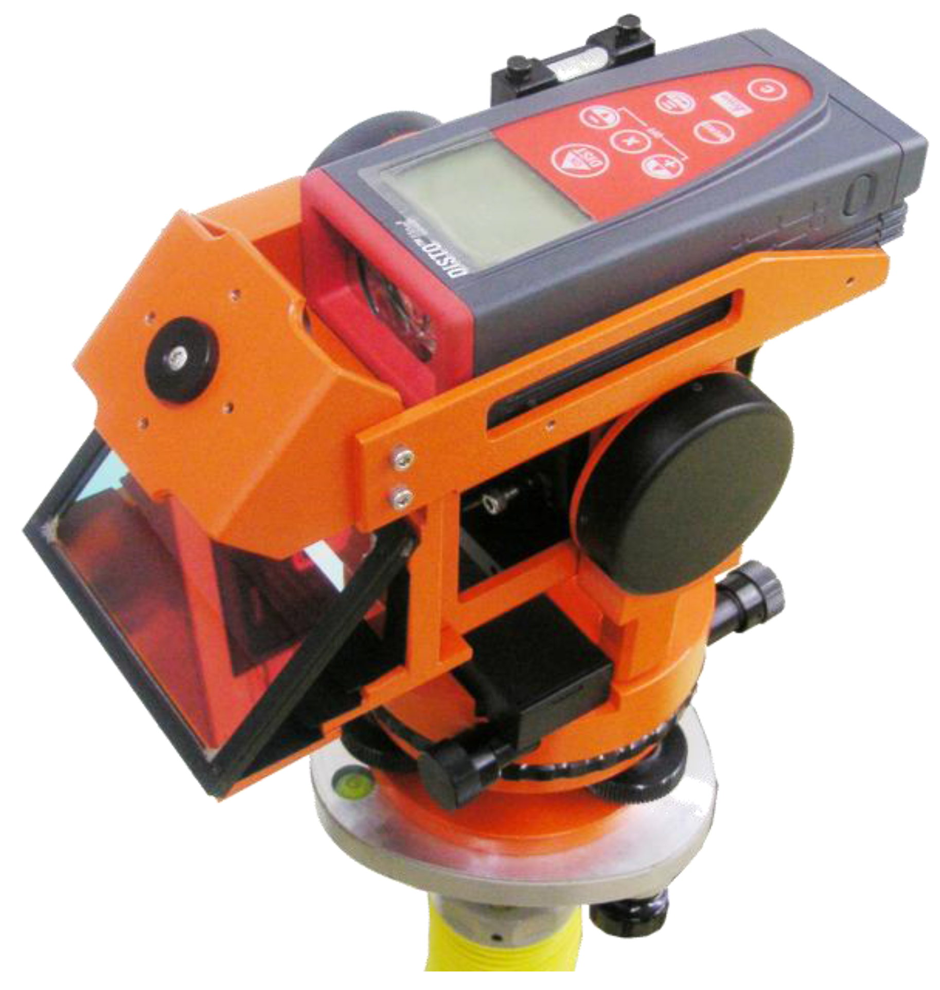
Ohdake and Chikatsu [
6] developed the IBIM system device, which consists of a consumer-grade digital camera (OLYMPUS C-770 Ultra Zoom, 4.0 megapixels), a laser distance meter (Leica Geosystems DISTO Lite 4, accuracy: ±3 mm [
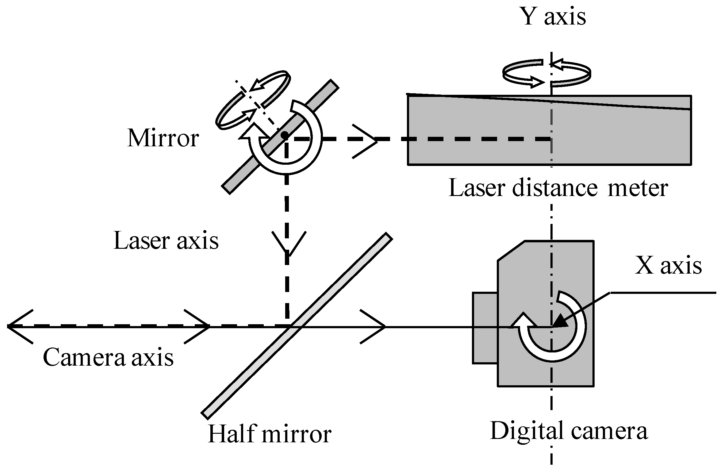
8]), and full/half-mirrors. Furthermore, the device is able to rotate both vertically and horizontally, so that precise distance from the center of the digital camera to feature points on the object field can be measured.
Figure 1 shows the IBIM system device, while
Figure 2 shows its configuration.
The IBIM system was originally proposed using the stereo method, where it is used at two different stations such as a left and right station in order to acquire stereo images and two bundles of distances. However, the stereo method has some issues when it comes to the IBIM system. One is deterioration of image quality, which is caused by acquiring images through the half-mirror, while the other is that distance measurement is laborious and time consuming when it comes to measuring the same feature points from different stations. Therefore, IBIM system was improved by authors using the triplet method, which employs triplet images and a bundle of distances [
7]. To prevent the deterioration of image quality, the images of both sides in triplet images are taken using other digital cameras, and the bundle of distances is measured at a center station to reduce labor when it comes to distance measurement. The IBIM system’s triplet method adopts a camera-variant parameter set for multiple cameras of different resolutions. The camera-variant parameter set was defined as calibration parameters for each camera and are unknown values. In other words, the unknown parameters of the camera-variant parameter set are the interior orientation parameters for each respective image.
Figure 1.
IBIM system device.
Figure 1.
IBIM system device.
Figure 2.
Configuration of the IBIM system device.
Figure 2.
Configuration of the IBIM system device.
In order to evaluate the efficiency of IBIM using the triplet method and the camera-variant parameter set, camera calibration was performed through indoor experimentation using a test target and eight digital cameras with block-invariant [
9], photo-invariant [
10], image-variant [
11], and camera-variant parameter sets.
Table 1 shows the specifications of the digital cameras.
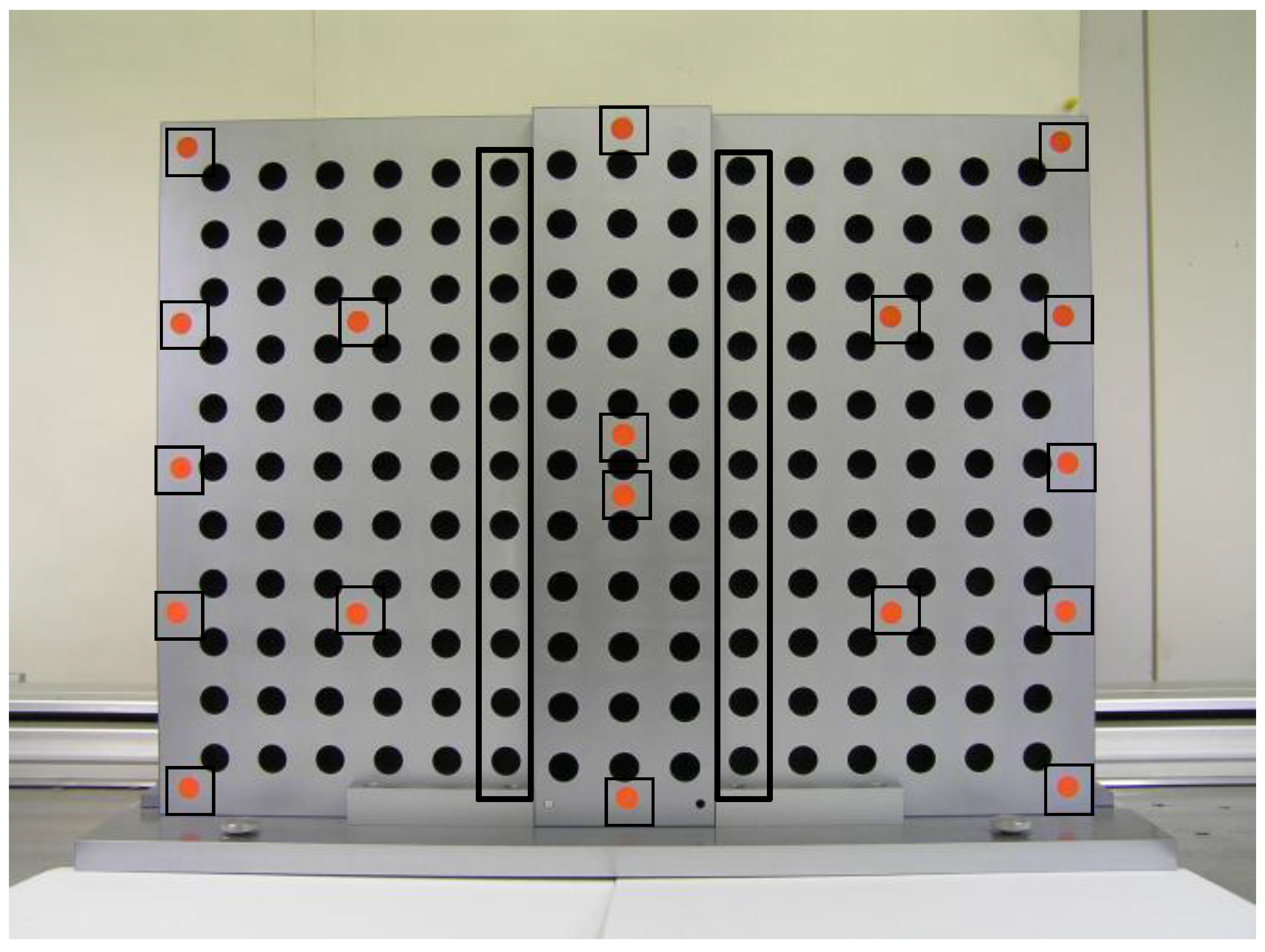
Figure 3 shows a test target (H: 640 mm, W: 480 mm, D: 20 mm) with 165 black circular points and 14 red circular points; it was used in this paper as a pseudo-GCP. It must be noted that the 3D coordinates of pseudo-GCPs are unknown, but the pseudo-GCPs are used for camera calibration in this paper. The 143 black circle points outside of the thick-line rectangle are checkpoints. Each black circular point was manufactured with ±0.05 mm accuracy, and the pixel coordinates for these points were obtained as area gravity using image-processing procedures. Five triplet images were taken for every camera with a changing altitude between 0.65 and 0.96 m so that uniform image scales could be maintained. Moreover, camera calibrations were performed by simultaneous adjustment using the pseudo-GCPs and the bundle of distances.
Table 1.
Specifications of digital cameras.
Table 1.
Specifications of digital cameras.
| Supplier | Camera model | Pixel (M) | Lens (mm) | Sensor type/size |
|---|
| OLYMPUS | C-770Ultra Zoom | 4.0 | 6.3 | 1/2.5″ |
| SONY | Cyber-shot DSC-N1 | 8.1 | 7.9 | 1/1.8″ |
| Nikon | COOLPIX S600 | 10.0 | 5.0 | 1/2.33″ |
| PENTAX | Optio W60 | 10.0 | 5.0 | 1/2.3″ |
| Panasonic | DMC-FX100 | 12.0 | 6.0 | 1/1.72″ |
| Nikon | COOLPIX S710 | 14.5 | 6.0 | 1/1.72″ |
| Canon | EOS 20D | 8.2 | 17.0 | 22.5 × 15.0 mm |
| Canon | EOS Kiss X3 | 15.1 | 17.0 | 22.3 × 14.9 mm |
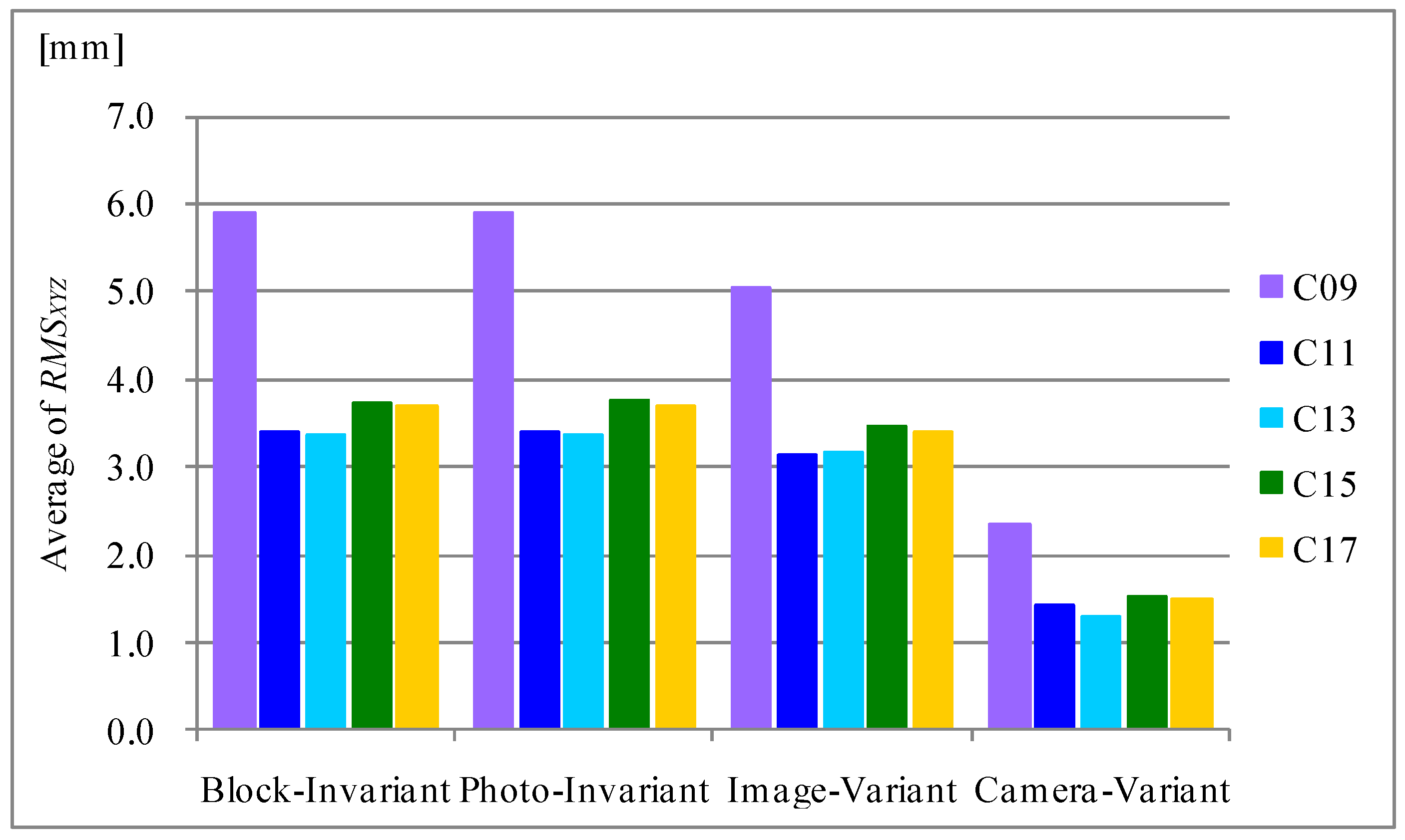
Figure 4 shows the relationship between an average of
RMSXYZ as accuracy and the number of pseudo-GCPs for each respective calibration model. In this case, the average of
RMSXYZ was computed using eight
RMSXYZ values, which were obtained from five measurements using 143 checkpoints with eight digital cameras. The
RMSXYZ represents the point error from Equation (1). Note that numbers such as C09 refer to numbers of pseudo-GCPs. The first feature of note in
Figure 4 is that it cannot find the significant differences between the block-invariant, photo-invariant, and image-variant parameter sets. On the other hand, the
RMSXYZ values of the camera-variant parameter set are small in comparison with other parameter sets, at 40%. It can be found that the accuracy of 15 and 17 pseudo-GCPs are lower than 13 pseudo-GCPs; it is inferred that accuracy is influenced by increasing the number of pseudo-GCPs located at the border. The results for nine pseudo-GCPs show the largest
RMSXYZ in each parameter set. Therefore, it is estimated that the IBIM system needs more than 11 pseudo-GCPs from the point of view of degrees of freedom. Consequently, it can be said that the camera-variant parameter set shows the most stable results.
where
σX, σY, σZ = RMSE of X, Y, Z
σXi, σYi, σZi = differences in X, Y, Z coordinates
nX, nY, nZ = numbers of checkpoints
Figure 4.
Influence of interior parameter set.
Figure 4.
Influence of interior parameter set.
Moreover, evaluation of the IBIM system using multiple cameras of different resolutions was performed using six combinations with eight digital cameras.
Table 2 shows combinations of digital cameras.
Figure 5 shows the normalized accuracy (
NA) for 143 checkpoints, which were computed from Equation (2). It should be noted that normalized accuracy means the ratio of
RMSXYZ in each type to standard error. Therefore, a ratio larger than 1 means higher accuracy than standard error, which is computed from Equation (3) [
12], and it is estimated that when accuracy exceeds standard error that pointing of image coordinates were performed using more than 1 pixel. The following results can be seen in
Figure 5:
- (i)
The IBIM system uses multiple cameras of different resolutions, and has the ability to obtain the equivalent accuracy with standard error.
- (ii)
The number of pseudo-GCPs does not have a significant influence on accuracy.
- (iii)
The IBIM system can obtain a stable result without the resolution of the digital cameras.
Table 2.
Combinations of digital cameras.
Table 2.
Combinations of digital cameras.
| Camera | Combinations | Resolutions |
|---|
| Left | Right |
|---|
| Cyber-shot DSC-N1 | COOLPIX S600 | N1-S600 | 8.1M-4.0M-10.0M |
| COOLPIX S600 | Optio W60 | S600-W60 | 10.0M-4.0M-10.0M |
| Optio W60 | DMC-FX100 | W60-FX100 | 10.0M-4.0M-12.0M |
| DMC-FX100 | COOLPIX S710 | FX100-S710 | 12.0M-4.0M-14.5M |
| COOLPIX S710 | EOS 20D | S710-20D | 14.5M-4.0M-8.2M |
| EOS 20D | EOS Kiss X3 | 20D-X3 | 8.2M-4.0M-15.1M |
Figure 5.
Normalized accuracy.
Figure 5.
Normalized accuracy.
Employing camera calibration techniques for IBIM system using the triplet method, the camera-variant parameter set exhibits about a 40% improvement from the point of view of accuracy compared with other parameter sets. Furthermore, the IBIM system using multiple cameras of different resolutions can obtain an equivalent accuracy to the standard error.
where
where
σX0, σY0, σZ0 = standard error
H = altitude: object distance
f = focal length
B = base distance
σP = pointing accuracy.
3. Application of IBIM System at Archaeological Sites
The IBIM system using the triplet method can be combined with multiple digital cameras of different resolutions, allowing it to attain non-contact measurements without scale bars or GCPs. However, a camera calibration that does not depend on the IBIM system device is required from the point of view of practical measurement. With this motive, camera calibration was investigated through a bundle of distances using a hand-held laser distance meter and images based on the concept of the IBIM system. The IBIM system that does not depend on the IBIM system device is called the generalized IBIM (G-IBIM) system.
The basic procedures of the G-IBIM system are the same as for the IBIM system using triplet digital cameras with different resolutions, excepting the method of distance measurement at the center station. In order to realize the G-IBIM system, the center image and distances were acquired using a tripod to relate each position of the hand-held laser distance meter with the digital camera. An offset between the origin of the laser distance meter and the sensor position of the digital camera that was mounted on the tripod has been measured.
The distances to the pseudo-GCPs from the camera center should be corrected by responding to the rotation. However, this correction is out of scope because the rotation value cannot be acquired; thus, the distances were measured by a hand-held laser distance meter (Leica DISTO D5, accuracy of ±1 mm [
13]) in the G-IBIM system. The hand-held distance meter has the function of a digital-point-finder mode, which shows the feature point on the display. Longer distances and precise measurements can be acquired in bright sunlight.
3.1. Coordinate System
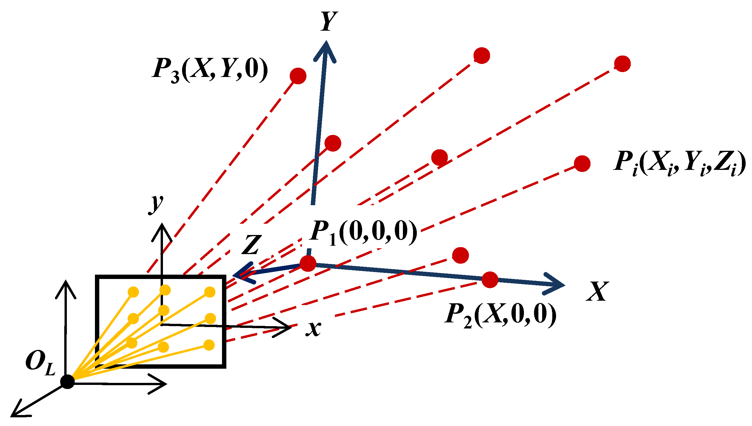
The G-IBIM coordinate system is a local coordinate system that takes an absolute orientation into account.
Figure 6 shows the coordinate system, which is defined as follows:
- (i)
The origin is OL, which is the origin of the hand-held laser distance meter. OL is not strictly equal to OC, which is the exposure point of the center of the digital camera. Therefore, the system takes offset OL to OC into account.
- (ii)
The 3D coordinates of pseudo-GCPs are computed by the image coordinates and distances, which are adjusted by an offset.
- (iii)
The 3D coordinates of the pseudo-GCPs are transformed into a local coordinate system, where P1 is the origin point.
- (iv)
The X-axis direction is given by another pseudo-GCP (P2).
- (v)
The Z value for the pseudo-GCP (P3) is given as 0.
Figure 6.
Coordinate system of the G-IBIM scheme.
Figure 6.
Coordinate system of the G-IBIM scheme.
3.2. Initial Values of the Pseudo GCPs
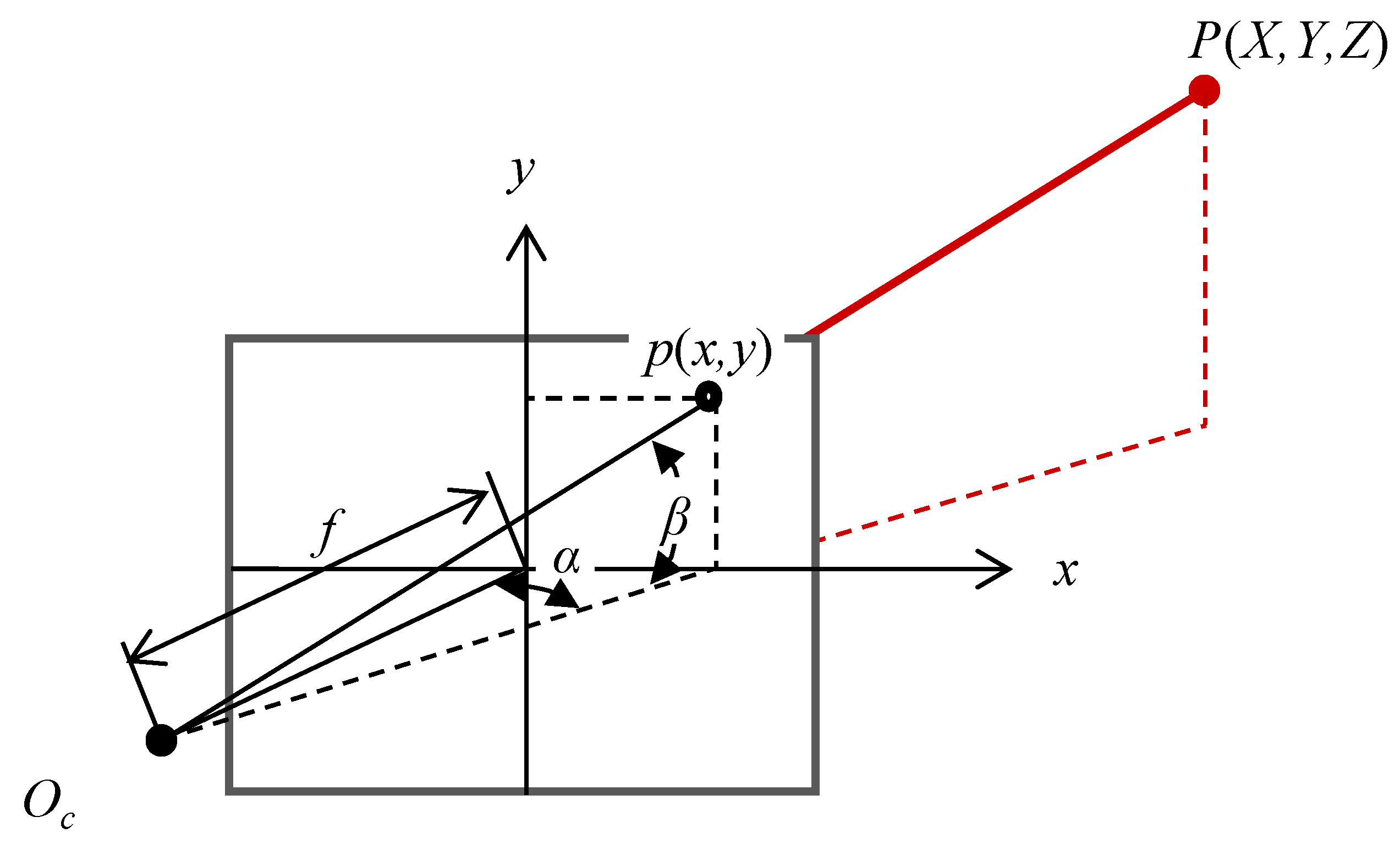
The initial values of the pseudo-GCPs are computed using their relationship with the bundle of adjusted distances, focal length, and image coordinates from the center of the digital camera. The horizontal (
α) and vertical angle (
β) are computed with the image coordinates and nominal focal length using Equation (4) [
14]. The 3D coordinates of the pseudo-GCP
Pi in
Figure 7 are obtained using the angles and the adjusted distance from the center of the digital camera (
OC) into
Pi using Equation (5).
Figure 7 shows the geometric condition of the pseudo-GCP.
Figure 7.
Angles of the pseudo-GCP.
Figure 7.
Angles of the pseudo-GCP.
where
where
X, Y, Z are the initial value of the pseudo-GCP’s on-ground coordinates
D = distance from the feature point to the perspective center.
On the other hand, each approximate exterior orientation parameter of the triplet images is calculated by perspective projection using the pseudo-GCPs and the nominal value of the interior orientation parameters.
3.3. Camera Calibration of the G-IBIM System
The unknown parameters of the G-IBIM system are the exterior parameters (X0, Y0, Z0, ω, φ, κ) and the interior parameters (f [focal length], u0, v0 [principal points], a, b [scale factor, shear factor], K1, K2 [lens distortion]) for the triplet images and the pseudo-GCPs (Xi, Yi, Zi), respectively. These unknown parameters under the local coordinate system are calculated simultaneously by the collinearity condition, distance condition, and geometric constraint condition. Here, the collinearity condition is shown as Equation (6), and the distance condition is shown as Equation (7). The camera calibration of the G-IBIM system is performed by calculating these unknown parameters, which can be calculated as values by minimizing the following function H (Equation (8)) under the least squares method.
The relationship between the number of pseudo-GCPs and accuracy is discussed above (
Section 2): nine pseudo-GCPs were adopted to take into account the fact that the geometric constraint condition was given as an observation equation and under the assumption that the interior orientation parameters do not change significantly from the initial values.
where
x, y = image coordinates
f = focal length
X, Y, Z = object coordinates of pseudo-GCP
X0, Y0, Z0 = perspective center
mij = elements of the rotation matrix.
where
where
Δxij, Δyij = residuals for image coordinates
ΔDj = residuals for distance
m = number of pseudo-GCPs
n = number of images
p1i = weight for image coordinates
p2 = weight for distance.
Regarding the lens distortion model, the radial polynomial 5th degree of Equation (9) [
15] was adopted in this paper.
where
x, y = corrected image coordinates
x', y' = image coordinates
K1, K2 = coefficients of radial distortion
r = radial distance from principal points
3.4. Evaluation
In order to evaluate the possibility and practicability of the G-IBIM system, experiments were performed in Greece using the proposed methodology.
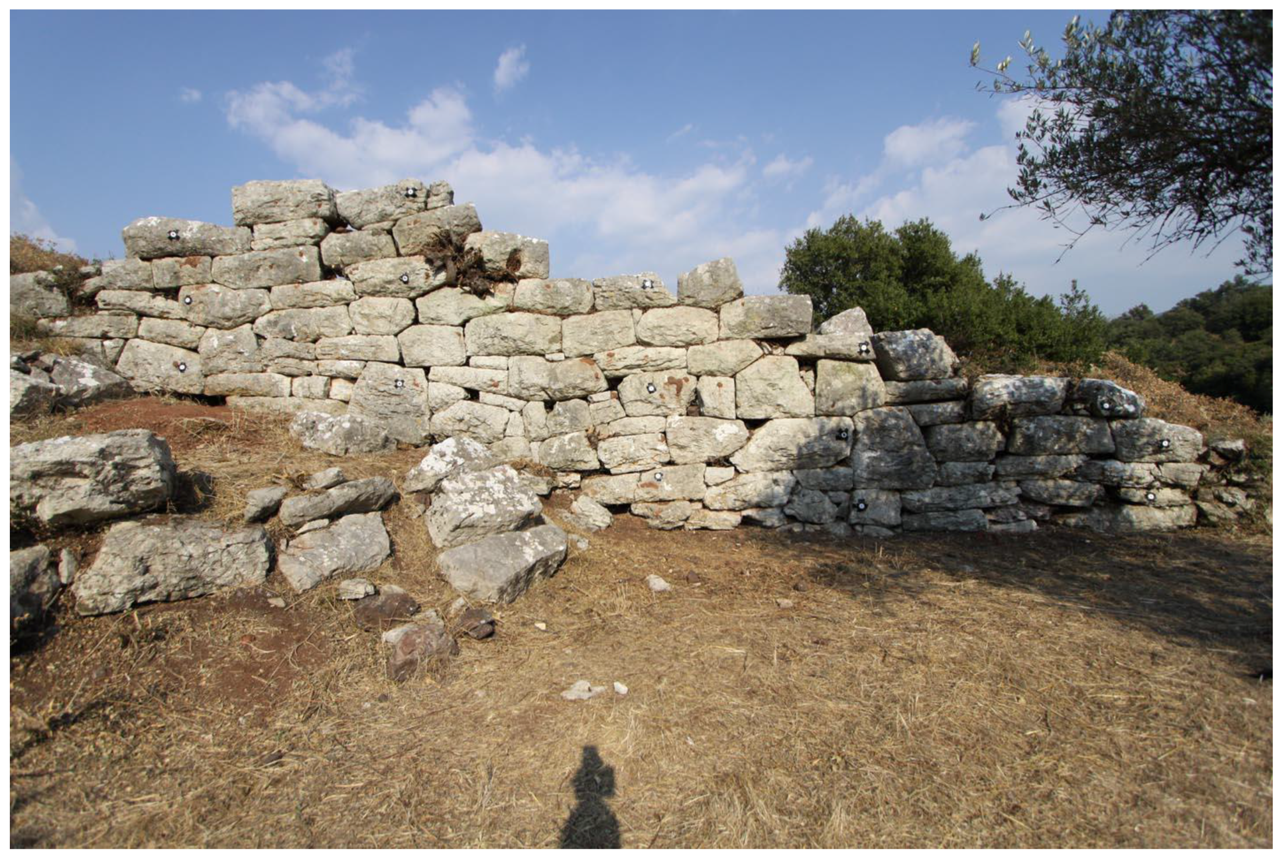
Figure 8 shows an image of a city wall, which was taken from an SLR camera at about 7 m (altitude height: distance from wall to camera). The city wall is located in Phigalia, which is an ancient Greek city in the west of Peloponnesus, and is located about 180 km southwest of Athens. It occupies an area of 2.5 km (east-west) by 1.5 km (north-south), and had many public buildings like temples, theaters, gymnasiums, and so on; it has never been excavated systematically.
Architectural scientists document ancient architecture through architectural surveys. The documentation is performed by planimetric mapping, and depth is not evaluated because this is too complicated for the traditional method. The scale for the planimetric map is selected by the architectural scientists depending on the object’s size. Generally, a 1:50 scale is adopted for appearance and a 1:20 scale for details. Thus, from a practical perspective, if the planimetric tolerance of the map is 0.5 mm, the planimetric accuracy in the object field becomes 10 mm on a 1:20 map. Similarly, planimetric accuracy is 25 mm for a 1:50 map. Therefore, it may be said that the practical objective for the G-IBIM system is 10 mm to 25 mm in planimetric accuracy.
On the other hand, length measurement error (LME) has often been used for the development of optical measurement devices [
16]. Of course, LME cannot be applied directly to the G-IBIM system; evaluation was performed using two criteria: planimetric accuracy and LME in the session.
Fifteen white circular targets for accuracy evaluation can be seen in
Figure 8; the X,Y,Z values of the points were obtained by a Total Station (Leica Geosystems FlexLine TS09, distance measurement accuracy is 1 mm + 1.5 ppm, angular accuracy is ±1″ [
17]), and the image coordinates were measured manually with one-pixel accuracy.
Table 3 shows the major data components.
Figure 8.
Appearance of city wall.
Figure 8.
Appearance of city wall.
Table 3.
Configurations of digital camera.
Table 3.
Configurations of digital camera.
| Supplier | Camera model | Pixel (M) | Lens (mm) | Sensor size |
|---|
| Canon | EOS 50D | 15.1 | 10.0 | 22.3 × 14.9 mm |
3.4.1. Accuracy
In order to evaluate accuracy, normalized accuracy was computed using 15 target points consisting of nine pseudo-GCPs and six checkpoints. The pseudo-GCPs are shown in the middle column and the columns on both edges, and the checkpoints are located in the other columns in
Figure 8. Normalized accuracy and standard error, as in
Section 2, were computed using Equations (2) and (3). Note that the standard error was computed under the assumption that image-coordinate pointing is accomplished with one-pixel accuracy.
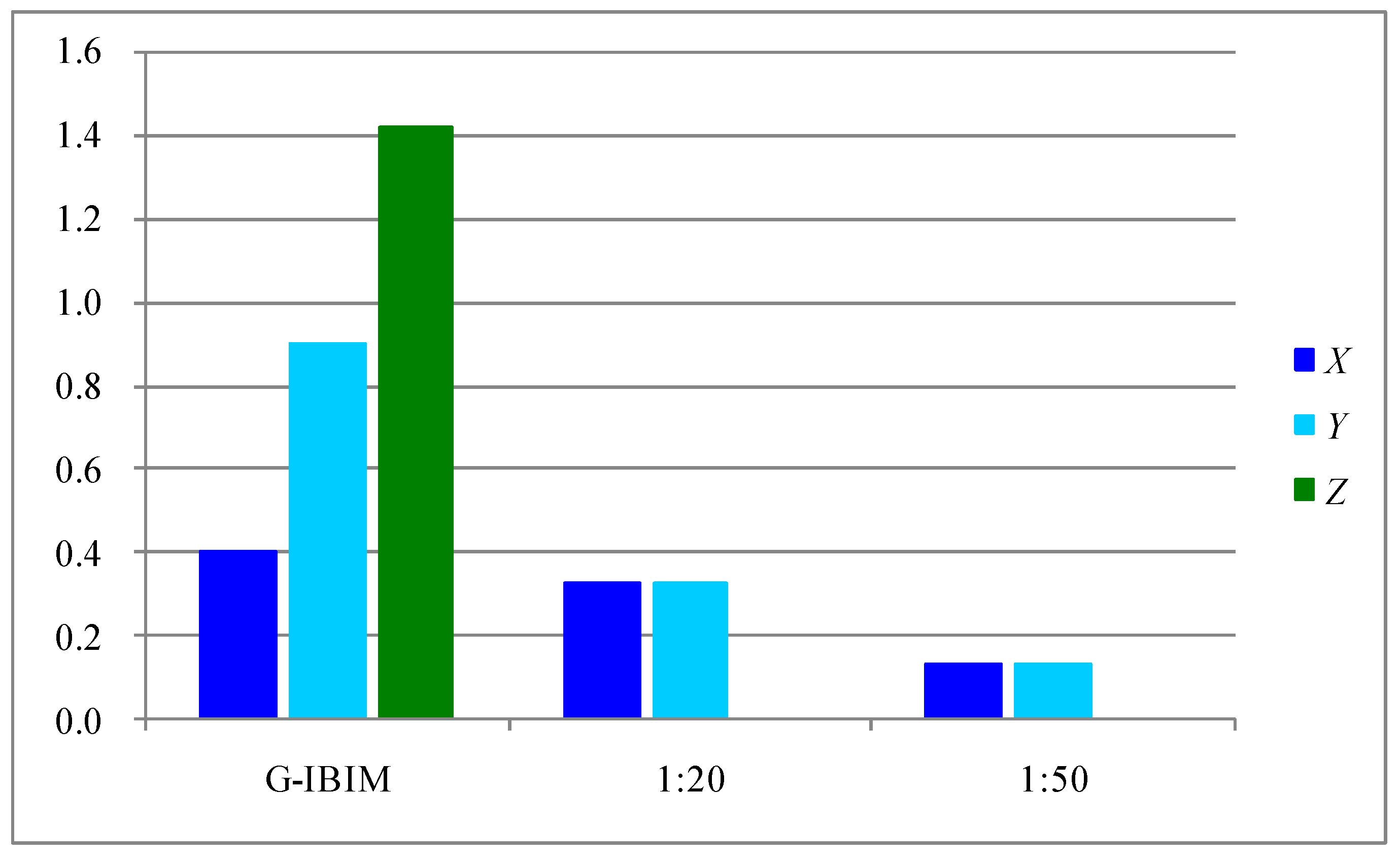
Figure 9 shows the normalized values, which are the normalized accuracy of G-IBIM system and the normalized tolerance of each scale of the planimetric maps. The normalized tolerance is computed in the same way as normalized accuracy, using standard error. Once more, it must be noted that a ratio larger than 1.0 in normalized accuracy means higher accuracy than standard error. From
Figure 9, it can be seen that the vertical coordinate value (
Z) is better than the horizontal coordinate values, since the vertical coordinates of pseudo-GCPs are constrained by measured distances as a characteristic of the G-IBIM system. By contrast, the horizontal coordinates (
X,
Y) do not satisfy the standard error. On the other hand, it is understood that the normalized accuracy of the G-IBIM system is large compared with its normalized tolerance; that is, G-IBIM system just satisfies the 1:20 map, and has obtained enough accuracy to create the 1:50 map. Therefore, it can be said that G-IBIM system can obtain practical accuracy only using distance information from the point of view of architectural survey practicability.
Figure 9.
Normalized accuracy.
Figure 9.
Normalized accuracy.
3.4.2. Length Measurement Error
The LME is the ISO-conforming criterion for the absolute accuracy of coordinate-measuring devices for high-accuracy measurement, such as in industrial photogrammetry [
18]. It is not appropriate to adopt the LME for this experiment because the LME investigates a length of 105 between all target points.
It is evaluated by using the indices of
RMSLME and
tLME, as well as Thomas
et al. [
18].
RMSXYZ as the point error is computed from Equation (1). The length deviation range is evaluated using extremal values, which consist of the minimum and maximum values.
RMSLME shows the deviation of all lengths and is computed by using Equation (10).
tLME is the theoretical threshold of the measurement of all lengths, and is given by Equation (11).
Table 4 shows each index respectively.
where
The length deviations range between −10.9 mm and +28.8 mm. With a point error RMSXYZ = 13.1 mm, a length precision of tLME = 55.7 mm can be achieved. RMSLME = 11.4 mm is smaller than tLME = 55.7 mm, and therefore the G-IBIM system has the ability to perform practicability measurements for ancient architectural documentation.
Table 4.
Results of measurements.
Table 4.
Results of measurements.
| RMS XYZ | 13.1 mm |
| RMS LME | 11.4 mm |
| LME | −10.9 ~ +28.8 mm |
| tLME | 55.7 mm |
In contrast,
Figure 10 shows the LME of the 105 distances. It can be found that the error cluster is on the plus side, and two distances are larger than 25 mm. However, almost all distances satisfy the 25 mm planimetric accuracy. This means that the G-IBIM system exhibits sufficient possibility of generating a 1:50 planimetric map.
Figure 10.
Length measurement error.
Figure 10.
Length measurement error.
3.4.3. Results for the City Wall
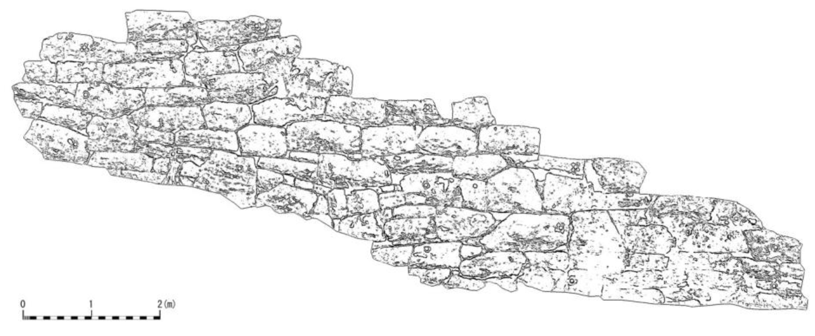
In order to investigate the adaptability and practicability of G-IBIM system, documentation of the city wall was performed. An ortho image was created using commercial photogrammetric software, which is able to import exterior and interior orientation parameters from the system. Furthermore, edge extraction for the underdrawing of the planimetric map was performed using a Canny filter [
19].
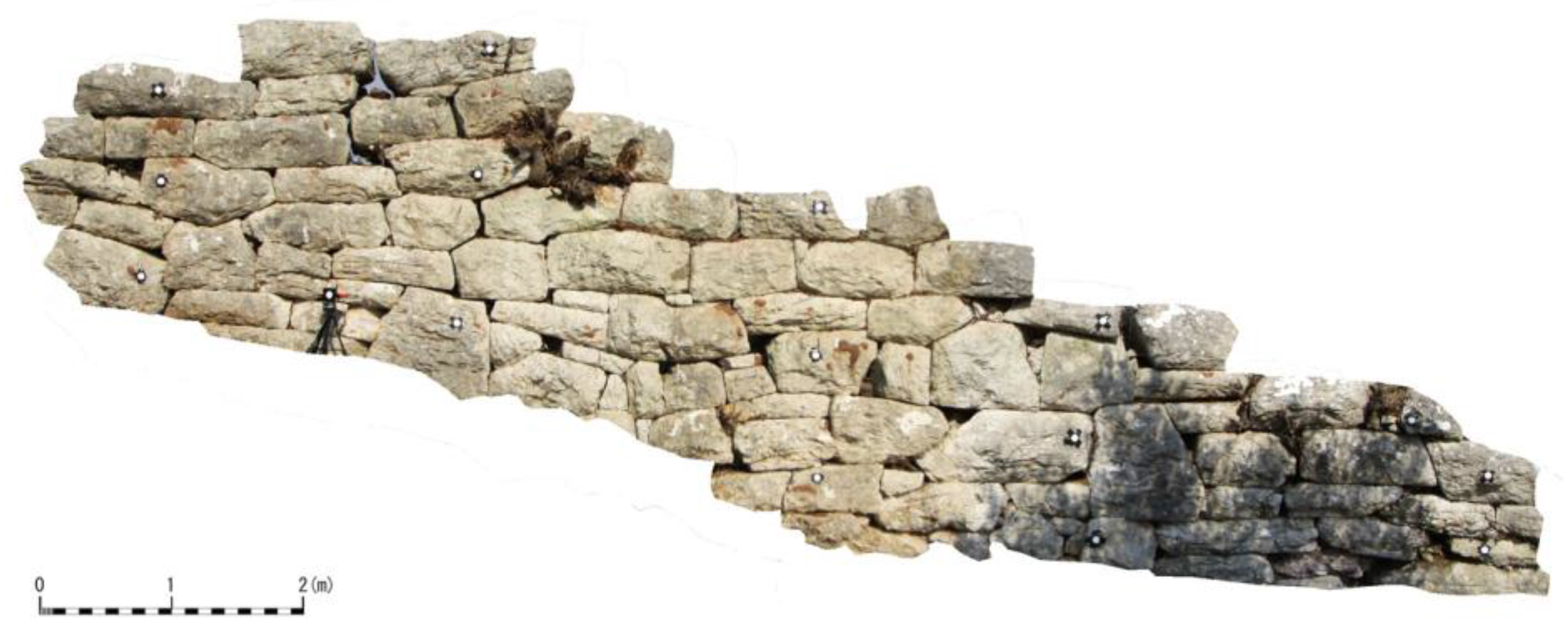
Figure 11 shows the ortho image and
Figure 12 shows the underdrawing of the planimetric map. The ground sampling distance of each image is 5 mm for a scale of 1:50. In particular,
Figure 12 constitutes a useful map for architectural scientists or archeologists in terms of generating sketch figures for architectural understanding.
Figure 11.
Ortho image of city wall.
Figure 11.
Ortho image of city wall.
Figure 12.
Edge extraction image.
Figure 12.
Edge extraction image.
4. Conclusions
The G-IBIM system, which uses digital cameras and a hand-held laser distance meter, was developed by the authors for practical digital photogrammetry. The camera calibration techniques and performance evaluation of the G-IBIM system were investigated in this paper.
The primary experiment was performed to evaluate the IBIM system, and the effectiveness of the camera-variant parameter set for triplet images and the bundle of distances were verified in the first parts of this paper.
Secondly, in order to accomplish a practical photogrammetry, a methodology was proposed using the G-IBIM system, and camera calibration techniques that do not depend on the IBIM system device were evaluated from the viewpoint of accuracy. As a result, it can be said that the G-IBIM system has the ability to generate a 1:50 planimetric map.
Thirdly, IBIM and G-IBIM system have the ability to obtain an object’s coordinates without GCPs, scale bars, or interior orientation parameter sets acquired beforehand. Note that circular targets were used to check the accuracy evaluation in this paper; however, IBIM and G-IBIM system can be utilized as the pseudo-GCPs for feature points on the images.
Consequently, it is concluded that a practical 3D measurement can be accomplished by the G-IBIM system using digital cameras and a hand-held distance meter; the IBIM system is expected to become a useful measurement system for various close-range photogrammetric application fields from the viewpoint of non-contact measurement and practicability.


