Gigapixel Imaging and Photogrammetry: Development of a New Long Range Remote Imaging Technique

1
Norwegian Geotechnical Institute, Oslo 0855, Norway
2
Classics Department, Queen’s University, Kingston, ON K7L 3N6, Canada
*
Author to whom correspondence should be addressed.
Remote Sens. 2012, 4(10), 3006-3021; https://doi.org/10.3390/rs4103006
Submission received: 18 July 2012
/
Revised: 11 September 2012
/
Accepted: 26 September 2012
/
Published: 10 October 2012
(This article belongs to the Special Issue Earth Observation Technology Cluster: Innovative Sensor Systems for Advanced Land Surface Studies)
Abstract
:The use of terrestrial remote imaging techniques, specifically LiDAR (Light Detection And Ranging) and digital stereo-photogrammetry, are widely proven and accepted for the mapping of geological structure and monitoring of mass movements. The use of such technologies can be limited, however: LiDAR generally by the cost of acquisition, and stereo-photogrammetry by the tradeoff between possible resolution within the scene versus the spatial extent of the coverage. The objective of this research is to test a hybrid gigapixel photogrammetry method, and investigate optimal equipment configurations for use in mountainous terrain. The scope of the work included field testing at variable ranges, angles, resolutions, and in variable geological and climatologically settings. Original field work was carried out in Canada to test various lenses and cameras, and detailed field mapping excursions were conducted in Norway. The key findings of the research are example data generated by gigapixel photogrammetry, a detailed discussion on optimal photography equipment for gigapixel imaging, and implementations of the imaging possibilities for rockfall mapping. This paper represents a discussion about a new terrestrial 3-dimensional imaging technique. The findings of this research will directly benefit natural hazard mapping programs in which rockfall potential must be recorded and the use of standard 3-dimensional imaging techniques cannot be applied.
1. Introduction
Mapping and monitoring of natural and man-made slopes is an extremely diverse and challenging field. As of the 2000s, a philosophical shift has occurred within the community to embrace advanced high resolution 3-dimensional (3D) digital imaging techniques. The primary applications of remote imaging tools are to enable engineers to better understand the dynamics of the mass movements, to facilitate the assessment of the hazard, and to assess the degree of instability through the detection of surface changes. This enables the development of accurate early warning systems and precautionary measures. The two most commonly employed and practiced imaging tools, and most published in the academic literature, are Light Detection and Ranging (LiDAR) and stereo-photogrammetry. The published literature is immense; common topics are hardware advances, algorithm developments, the optimization of processing workflows, and innovative applications of the data [1–3].
Remote imaging techniques have a distinct advantage over observational approaches for mapping and monitoring of landslides and rockfall. As data is collected at specific points in time, in a true 3D space, comparison of data over time can enable the calculation of rockfall rate, pre-failure deformation, and mechanics of the movement. The principle use of the equipment is the ability to generate data depicting a specific site, at a specific point in time.
LiDAR and digital stereo-photogrammetry are accepted techniques because they are easily understood, the results are visual, data are accurate, the equipment is reliable, and the processing options are diverse. There are, however, drawbacks to these imaging tools for long term detailed monitoring programs, which are explained in detail in the following sections.
The research presented in this paper outlines the development of a hybrid digital photogrammetic technique that eliminates the traditionally accepted tradeoff between spatial coverage and resolution of traditional stereo-photogrammetry. By collecting gigapixel photographic images, not standard megapixel images, the generation of extremely high resolution 3D surface models is possible using standard photography equipment. This paper will discuss the development of gigapixel photogrammetry, illustrate example data, and address the implications for geological mapping, structural evaluation, and landslide/rockfall hazard mapping. As this field of study is novel, this paper is presented only as an initial foray on the capabilities of a new approach to digital stereo-photogrammetry using gigapixel imagery. All data used in this paper will be made publicly available through the website www.rockbench.org [4] as a way to aid in the development of this technique and testing its accuracy.
2. Digital Photogrammetry
The fundamentals of gigapixel photogrammetry lie within the understanding of traditional stereo-pair photogrammetry. As such, the following sections outline the basic principles of traditional photogrammetry and how this knowledge is applied to the development of data acquisition and processing techniques for gigapixel photogrammetry.
2.1. Traditional Methodology
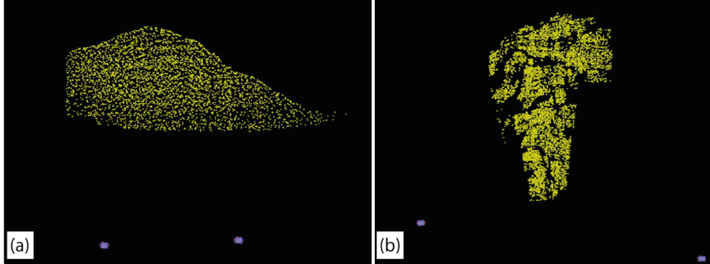
Traditional baseline stereo-photogrammetry, of the sort used for decades in both terrestrial and aerial applications, works by comparing two overlapping images (overlap typically in the range of 60–70%) to calculate by triangulation of light rays 3D points in the overlapping area. Such overlapping images can be linked up to generate long “strip” models. Non-baseline photogrammetry is used in cases where the entire subject can be captured in a single camera frame. Two or more camera positions “converge” to capture the entire subject. So-called “fan projects” are a hybrid of base-line and non-baseline techniques and are a particular strength of ADAMTech [5] 3DM CalibCam [6]. In this case several camera stations are established about which the camera pans to take many images. Each of these images in a camera station overlaps with other images taken by adjacent camera stations to create many small, but linked, convergent pairs, as illustrated in Figure 1; the linked points within the images are known as bundle points. As well, the software does not require ground control points as is necessary with various other packages [7]. A practical engineering geology example would be using several camera stations set-up at points at a constant distance to a rock face to increase the resolution of the model, much as is done in a strip project, and to minimize occlusions by reducing look-angle. This approach is common between LiDAR and photogrammetry [8].
The robust mathematics of photogrammetry permit the a priori prediction of accuracy in depth and in plane based on the parameters of the camera and geometry of the project. Chiefly, the base-to-distance ratio, where base is the distance between the cameras or stations, and distance is the distance from the cameras/station to the subject. While planimetric accuracy is high with photogrammetry, the depth accuracy is a function of base-to-distance ratio. While a low base-to-distance ratio (1:1) yields optimum depth accuracy a base-to-distance of 1:2–1:7 is more common. Good, photogrammetrically-derived models will always be the result of a compromise between base-distance ratio and look-angle that is optimized for the particular field location [9–12].
2.2. Gigapixel Photography
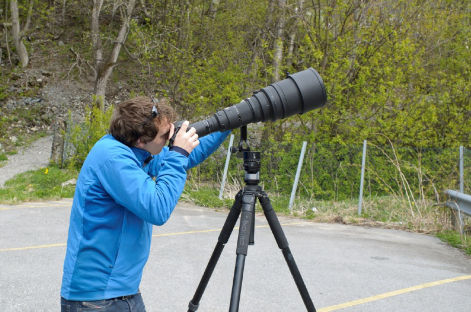
Gigapixel images are images of a resolution equal to or greater than 1,000 megapixels, a number that vastly exceeds commercially-available single-sensor cameras. There are two commercially viable ways to capture gigapixel images today, one of which is to use a robotic head developed by GigaPan, while the other is to use a manual pano-gimbal head. The GigaPan unit was developed through the Global Connection Project to create a commercial front-end to the powerful NASA Vision Workbench C++ library [11]. The robotic GigaPan head (Figure 2) automates what is otherwise the time consuming and tedious process of capturing the hundreds of images required for a high-resolution, long-range fan project.
Proper stitching of gigapixel images requires the camera and lens combination to rotate around the no-parallax point (NPP), which corresponds to the entrance pupil of the lens (the term “nodal point” has now been deprecated, and the term no-parallax point is preferred since there are multiple nodal points along a lens) [13]. Rotation around this point eliminates the effect of parallax, which is the movement of two distant objects relative to one another when viewed from different angles. The need to rotate the camera around this point necessitates the use of such specialized tripod heads. The GigaPan EPIC Pro is ideal for ease and speed of use, but with long telephoto lenses the no-parallax point can be located behind the sensor plane. This is an issue for the motors in the robotic head, which do not have enough torque to manipulate heavy lenses extended forward to their no-parallax point. The longest lens we have successfully mounted on the GigaPan at its no-parallax point is the 300 mm f4 AF on a Nikon D7000, as illustrated in Figure 2.
The GigaPan Stitch software, which automated the reconstruction of the 2D gigapixel image, is the result of a research collaboration between the NASA Ames Intelligent Robotics Group and Carnegie Mellon University with Google sponsorship to develop a high-resolution imaging technique and interactive viewing solution for use on the Mars Rovers.
GigaPan images are viewed as standalone, high-resolution landscape images, which are extremely useful for geomorphological mapping, as illustrated in Figure 3. This technique is commonly used by the authors as a documentation and evaluation tool for the identification of high mountain hazards and establishing a level of rockfall activity. Stock et al. [14] takes the process one step further and presents the use of a 2D GigaPan image as a textured overlay to 3D LiDAR data collected in Yosemite National Park for the evaluation of rockfall hazards.
2.2.1. Gigapixel Photogrammetry
Digital stereo-photogrammetry, as explained above a d published by various researchers referenced in this paper, is a standard remote sensing process. Generally speaking there is a trade-off between spatial coverage and resultant resolution of the 3D generated point cloud. This is because as one increases spatial coverage the angle of the lens must be lowered to accommodate the scene. However, using photographs collected for a 2D gigapixel panoramic image as inputs to the photogrammetry model, the only considerations are data volume and time required for image collection in the field.
The use of gigapixel imagery for photogrammetry requires that extreme care be taken concerning image overlap. Side-lap of 66% is ideal, while 20% vertical overlap is sufficient. It is critical to capture images with adequate overlap for the distortion of the lens to be modeled, calibrated, and the effects removed. Overlap applies to photos taken within a camera station, as well as to photos between camera stations. Similar to a convergent pair stereo-photogrammetry model, camera stations should have as near to 100% overlap as possible, while maintaining a good base-to-distance ratio. By capturing multiple GigaPans, one can generate high-resolution 3D data by strictly optical means using inexpensive, commercially available hardware.
3. Data Acquisition and Processing
3.1. Instrumentation and Field Setup
The basis of a good field setup for gigapixel imagery is the choice of camera and lens. A Digital Single Lens Reflex (DSLR) camera and a telephoto lens are requirements, in addition to a robust tripod and a specialized robotic or manual head. There are a number of factors that influence camera and lens selection in gigapixel imaging, chief among them is sensor size and focal length. There are pros and cons for using a full frame sensor versus a cropped sensor. For one, a full frame sensor will capture the highest quality images in terms of dynamic range, resolution and low noise. As imaging technology moves forward, however, cropped sensor cameras are increasing in quality, and, because they inherently increase the focal length of the lens, can be very useful for long range work. Most consumer DSLR cameras have cropped sensors (crop factors of 1.5× on Nikon, and 1.6× on Canon), are relatively inexpensive, and have excellent image quality. Even smaller cameras with interchangeable lens mounts have become available in the last few years with crop factors of 2× (Micro 4/3) and 2.7× (Nikon V1 and J1), which allow for more affordable telephoto lenses to be used to greater effect at long ranges. For instance, a 600 mm lens with a 2× teleconverter on a Nikon V1 has an effective focal length of 3,240 mm.
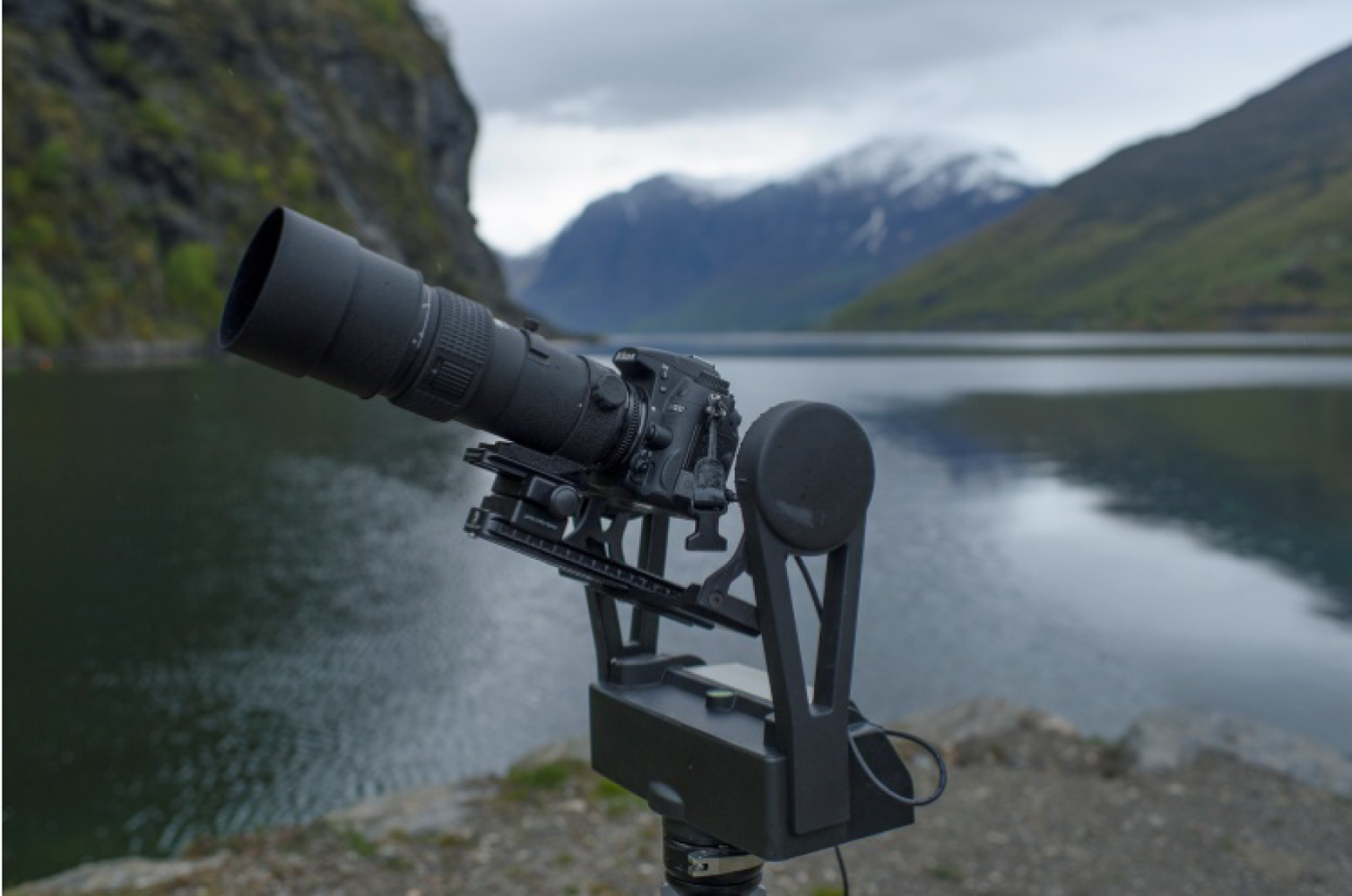
Lens selection for gigapixel image capture depends on the required resolution of the final result. One can use lenses as wide as 105 mm and achieve a good result, however the longer the focal length, the greater the pixel/ground resolution. Prime (fixed focal length) lenses are preferred, because zoom lenses have more moving parts and thus leave more room for error. Longer telephoto lenses can create an issue when used in conjunction with a robotic GigaPan unit. They are inherently long and heavy and because the GigaPan EPIC Pro is a commercial unit, it is not robust enough to handle payloads much larger than 2 kg; we were able to support a Nikon D7000 (780 g) with a 300 mm f4 AF (1,330 g). The next longer focal length, 400 mm, is in another weight class entirely, with the newest Nikon 400 mm f2.8 weighing 4.4 kg, which requires the use of a more robust, manual pano-gimbal head. Another issue with long telephoto lenses is locating the no-parallax point, which can be located behind the sensor plane. This makes mounting it on a GigaPan head unfeasible. For gigapixel setups with lenses longer than 300 mm, a heavy duty manual pano-gimbal head is required to manage the weight. However, rotation around the no-parallax point is impossible with this set-up because of the weight distribution, as illustrated in Figure 4. This causes errors in stitching gigapixel images, but can still be modelled in ADAMTech.
The general rule for sharp imagery is to shoot with a shutter speed no slower than the focal length of the lens, i.e., 1/200 s at 200 mm, but a faster shutter speed is always ideal. Telephoto lenses have very shallow depth of field, and in order to capture consistently sharp images of a highly irregular rock cut, more depth of field is needed. All lenses have an ideal aperture setting before diffraction reduces image quality. Diffraction is the effect of light waves being compressed by the diaphragm of the aperture resulting in lower resolution. With an ideal aperture selected for a particular shooting situation, the shutter speed needed for a good exposure may be too slow to yield a sharp image. In order to increase shutter speed, ISO (the sensitivity of the image sensor) must also be increased. The native ISO of a camera will yield the highest quality images (100 ISO on Canon, 200 ISO on Nikon), however in order to use a shutter speed that will allow the capture of a sharp image, ISO may need to be increased to a point where noise becomes an issue. Use of a modern, high quality DSLR is important for low noise at high ISO values, as noisy images mean noisy photogrammetric models.
3.2. Data Processing
3.2.1. RAW Image Processing
When capturing images, it is important to always capture the highest quality image possible. To do so, the camera should always be set to a RAW format, uncompressed or lossless compressed at the highest bit depth possible. Compared to JPEG images, RAW images have more latitude in post processing. This ability to post process (up to 1.7 ev with no loss in quality) is important for gigapixel image construction because of the length of time it takes to capture one (between 20 min to 3 h), changing light conditions and a wide dynamic range of landscapes. The stitching of individual gigapixel images is simple and can be done with a wide variety of dedicated software. The GigaPan Stitch software is included with the purchase of a robotic head, but other suites include PTGUI, HugIn and Microsoft ICE. Each of these software suites will blend the constituent images into a single panorama. The constituent images, however, should be saved as they will be used for the photogrammetry.
3.2.2. 3-Dimensional Reconstruction
To convert gigapixel images into a 3D point cloud image must be collected following the fan setup model—the primary difference with the traditional methodology being that at each location hundreds of images will be taken. ADAMTech Calibcam is the first step in the 3D reconstruction process. To create a model, every individual photo must be imported into one of a number of camera stations. Each camera station represents a single gigapixel capture. In the process of creating this 3D model, Calibcam can also merge the photos together and output an orthorectified 2D panoramic image.
All images must first be matched within their own camera station, and then each camera station must be matched image by image. Calibcam can do this automatically, but manual matching is sometimes necessary. At this stage the ability to reference a fully stitched gigapixel image will enable faster referencing between images collected at different camera stations. By supervising the generation of bundle points between the hundreds of image pairs we have been able to obtain an image accuracy of 0.1 pixels. That is to say, the models are accurate to within 1/10th of the size of a ground pixel, i.e., the pixel projected into the real world. The accuracies achieved by this hybrid fan based photogrammetry are equal to that of standard photogrammetry as no separate algorithms or processing is required. It should be noted that the generation of a point cloud from the gigapixel input images can take multiple tens of hours. This, however, can be optimized by using parallel computing techniques and faster workstations.
3.2.3. Three Dimensional Surface Generation
Following the generation of the 3D point cloud from the gigapixel input images, they are imported as an unorganized point cloud into the PolyWorks IMAlign module [15]. The PolyWorks suite of software programs enable the unorganized point cloud to be converted to a true 3D meshed surface. The creation of a 3D mesh is desirable as it enables complex calculations of discontinuity orientations and volumetric measurements, and directional evaluations not possible in a 2.5D TIN based environment [16].
4. Field Sites
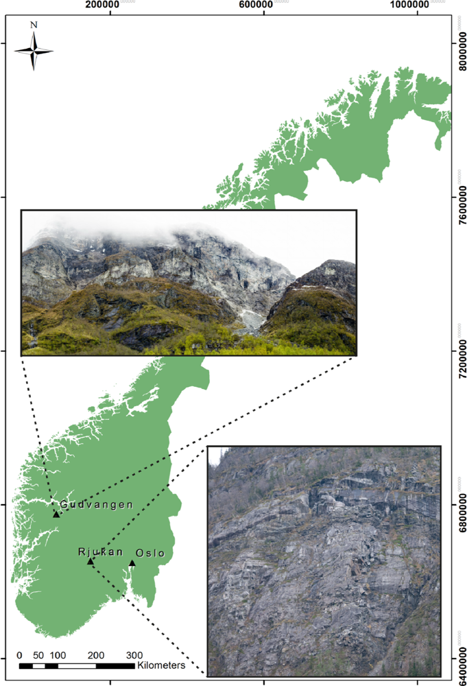
The development of data collection workflows and techniques were originally conducted in Kingston, Canada at simple outcrop settings; sites primarily consisted of highway roadcuts. This enabled rapid data collection and testing of various equipment components, setups and data processing routines. After approximately one year of detailed testing, a full scale field mission was conducted in May 2012 in Norway. The testing in Norway was conducted at two sites, one in the Rjukan Valley of central Norway and one in the Gudvangen Valley of Western Norway, as illustrated in Figure 5. The Gudvangen Valley is characterized by near vertical rock faces extending over 1,000 m above sea level from the valley floor. Both of these locations are challenging sites to conduct photogrammetry as there is a limited availability of locations from which to collect data, variable weather conditions (frequent rain, fog, and high winds), extreme topographical differences across the regions to be imaged, and no possibility of survey equipment for control on the imaged rock faces. However, the inherent challenges of the sites were the reason they were selected for this test. Information with respect to the photographic data collected at both sites that are used for the generation of the 3D photogrammetry point clouds are summarized in Table 1.
The density of the resultant 3D point clouds generated from the fan-based gigapixel images are reported in Table 2 as well as the pixel accuracy due to the reconstruction. However, it is critical to note that the accuracies reported in Table 2 represent those from the 3D reconstruction of the point cloud form the data. The errors reported are not based on a true scale. Thus meaning that for a given RMS error in the reconstruction process the effective spatial error will increase as a function of the distance between the camera and the object.
5. Results
The primary and tangible results of this preliminary research are the 3D surface models generated from the gigapixel photography. To illustrate the results in context, two 3D surface models are presented below as they would be used in a standard engineering geology evaluation of a rockmass using state-of-the-art stereo-photogrammetry or LiDAR data. These analyses are completed according to workflows and methodologies published by [17–23]. As well, data generated though this study at an early stage where used in a geological mapping exercise as published in the International Journal of Rock Mechanics and Mining Science [24].
5.1. Gudvangen
The complete Gudvangen dataset consists of two separate gigapixel images collected at the base of the slope; the resultant 2D images are 2.6 and 3.3 gigapixels. By selecting a subset of the full area that is of high interest near the peak of the mountain, a point cloud containing 22 million xyzrgb points was generated.
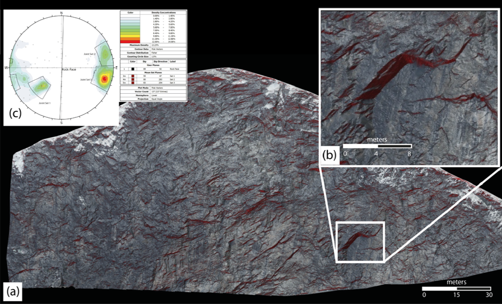
The rockmass under analysis in the Gudvangen Valley is a classical example of a mountainside that exhibits continual individual rock block failures. The engineering geological application of 3D data at this site is to assess zones of instability through evaluation of overhanging blocks and information relating to the structure of the discontinuities within the rockmass. Through the creation of the 3D surface model, which is generated from the points created in the gigapixel photogrammetric conversion, the user is able to use direction lighting to highlight specific features. In this example a red light is used to illuminate the model in the z (or upward) direction; this process allows the user to visually identify all overhanging rock blocks, as illustrated in Figure 6(a). As published by Lato et al. [18] this technique is extremely useful for a visual evaluation of the rockmass. Furthermore, as illustrated in Figure 6(c), discontinuity orientations are obtained directly from the meshed LiDAR data and plotted in a stereographic analysis program for kinematic evaluation of the geological structure [24]. Both of these typical analyses of digital data are extremely effective and efficient using gigapixel photogrammetry data.
5.2. Rjukan
The complete Rjukan dataset consists of three separate gigapixel images collected across a river and mid-way up the opposite slope face within the valley. By selecting a subset of the full area that is of high interest, a point cloud containing 93 million xyzrgb points was generated.
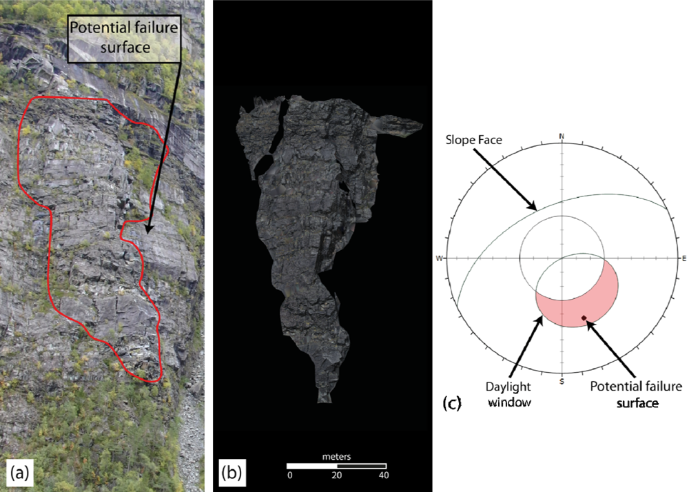
The rockmass under evaluation in the Rjukan Valley is of interest due to the unknown volume of large rock blocks positioned directly above a roadway. A potential failure surface has been mapped in the field as well as in the digital data; the potential planar sliding surface is identified in a photograph taken of the site in Figure 7(a). The orientation of this plane, as well as the slope face are measured in the 3D data and plotted on a stereonet as illustrated in Figure 7(c); thus enabling a trained engineer to assess the kinematic stability of the region. By isolating all 3D points that lie above the potential failure surface, converting the points to a mesh, as illustrated in Figure 7(b), the volume of the potentially unstable rock blocks can be measured. This evaluation process determined a maximum volume of 23,150 m3. This value compares well with the value measured using LiDAR data collected in 2010, which is calculated to be 22,700 m3, a difference of 2%.
6. Discussion
6.1. Implications of Research for Rockfall Hazard Management
There exist a plethora of remote sensing technologies and applications for the mapping and monitoring of natural geologically controlled hazards. The foremost methods, as pub ished in the academic literature, relate to landslide deformation [25], rock structure mapping [17–21,26] and automated discontinuity feature extraction from LiDAR data [23,26,27]. These methods rely on high-resolution 3D data. Data collection by LiDAR is expensive and weather-dependent. Data collection by y traditional stereo-photogrammetry is restricted in terms of distance and resolution [20]. The key benefit of gigapixel photogrammetry is that images can be collected efficiently, at a minimal cost, in variable weather conditions, and stored until 3D reconstruction is necessary. With current software, the 3D model reconstruction can be confined to critical regions within the entire gigapan image. Thus leaving full scale modeling left to a time when the computer hardware and software catches up, as surely it will. This method provides a 3D modeling solution with the range and resoluti on of terrestrial LiDAR scanners with the accuracy and affordability of digital stereo-photogrammetry.
6.2. Limitations and Future Research
The combination of gigapixel imaging and digital stereo-photogrammetry is a potent new remote sensing observational technology. The inherent scale-independence of photogrammetry allows for comparatively inexpensive modeling at ranges exceeding 1 km, and allows at the same time the capturing of colour data useful in monitoring rock falls and the identification of rock geology. The authors also believe that with increasing camera resolution important friction parameters such as surface roughness, an important metric for slide planes [28–29], may be assessed. While not currently part of a field geologist’s standard kit, the addition of a tripod, DSLR camera and GigaPan head is not unduly onerous. As addressed in the current literature, the applications and demand of high resolution photogrammetric solutions is high [30–32] and gigapixel photogrammetry should help enable an ever further implementation of this low-cost method of producing 3D topological data.
While gigapixel imaging with commercially available cameras and robotic heads can and should be implemented from today in natural hazard monitoring, several problems remain in the routine use of stereo gigapixel datasets to construct 3D models. First, the scaling and orientation of photogrammetry-derived models remain more difficult than for LiDAR. In remote areas survey-grade GPS or total stations can be difficult to bring to the field. With constant improvements, however, we believe that small decimeter or centimeter GPS receivers could be used to geo-tag photos as soon as they are acquired in the field to create a seamless recording workflow. Likewise, geotagging with a triple-axis compass could obviate the identification of vertical and/or horizontal planes in the images to establish absolute orientation. Second, the building of gigapixel-scale models remains very time consuming even with the premier software packages and fastest workstations. 64-bit software will be key for high-resolution photogrammetry projects in excess of 500 images, as will better automated tools for pair-matching hundreds or thousands of individual images. Third, a more robust survey-grade version of the GigaPan head that can support even longer professional telephoto lenses is desirable, though not essential given that the small market for such a tool may make its expense outweigh its benefits. As we have already suggested, improvements in digital sensor technology may make long telephoto lenses (focal length > 200 mm) unnecessary.
7. Conclusions
The research presented in this study illustrates an innovative approach to photogrammetry based on a hybrid fan-setup gigapixel photography, not traditional megapixel photography. The difference observed through the implementation of gigapixel images into a photogrammetry setup is the unprecedented density of the resultant 3D data. Results presented show point densities at over 9,000 pts/m2 at distances of approximately 800 m (equaling approximately 1 pt/cm2). The applied results in terms of structural mapping and geomechanics through volumetric assessment for natural hazard evaluation prove the usability of the data.
Gigapixel photography and gigapixel photogrammetry are emerging techniques in the world of ground based terrestrial remote sensing. Their potential applications are widespread as are the data collection and processing configurations. Gigapixel photogrammetry has an element of uniqueness as no literature exists on that subject within the geosciences community, and therefore it must be widely tested and validated before it will become a state-of-practice tool.
Acknowledgments
The authors would like to thank Marla Mackinnon for her assistance in the field and her assistance in building the models used. This work has been generously funded by the Norwegian Research Foundation through the Norwegian Geotechnical Institute. The authors would also like to thank Bjørn Sture Rosenvold from the Aurland Kommune for site access. As well the authors would like to thank Isabel Coderre for her editing.
References
- Remondino, F. Heritage recording and 3D modeling with photogrammetry and 3D scanning. Remote Sens 2011, 3, 1104–1138. [Google Scholar]
- Hanneberg, W. Using close range terrestrial digital photogrammetry for 3-D rock slope modeling and discontinuity mapping in the United States. Bull. Eng. Geol. Environ 2008, 67, 457–469. [Google Scholar]
- Mayer, H. Object extraction in photogrammetric computer vision. ISPRS J. Photogramm 2008, 63, 213–222. [Google Scholar]
- Lato, M.; Kemeny, J.; Harrap, R.M.; Bevan, G. Rock bench: Establishing a common repository and standards for assessing rock mass characteristics using LiDAR and photogrammetry. Comput. Geosci 2012. [Google Scholar] [CrossRef]
- ADAM Technology, 3DM Analyst Mine Mapping Suite 2.4.3, Build 1033; ADAM Technology: Belmont, Australia, 2011.
- Birch, J. Using 3DM Analyst Mine Mapping Suite for Rock Face Characterisation. In Laser and Photogrammetric Methods for Rock Face Characterization; Tonon, F., Kottensette, J.T., Eds.; Colorado School of Mines: Golden, CO, USA, 2006; pp. 13–32. [Google Scholar]
- Nakano, K.; Chikatsu, H. Camera-variant calibration and sensor modeling for practical photogrammetry in archeological sites. Remote Sens 2011, 3, 554–569. [Google Scholar]
- Lato, M.; Diederichs, M.S.; Hutchinson, D.J. Bias correction for static LiDAR scanning of rock outcrops for structural characterization. Rock Mech. Rock. Eng 2010, 23, 615–628. [Google Scholar]
- Matthews, N.A.; Noble, T. Aerial and Close-Range Photogrammetric Technology: Providing Resource Documentation, Interpretation, and Preservation. Technical Note 428; US Department of the Interior, Bureau of Land Management, National Operations Center: Denver, CO, USA, 2008. [Google Scholar]
- Kraus, K. Photogrammetry. Vol. 1: Fundamentals and Standard Processes; Dümmlers Verlag: Bonn, Germany, 1997. [Google Scholar]
- Luhmann, T.; Robson, S.; Kyle, S.; Harley, I. Close Range Photogrammetry: Principles, Techniques and Applications; John Wiley & Sons: New York, NY, USA, 2007. [Google Scholar]
- Naas Intelligent Systems Division. Ames Research Center. Intelligent Systems Division. Available online: http://ti.arc.nasa.gov/m/groups/intelligent-robotics/ARC-Partnership-News-Summer09.pdf (accessed on 2 July 2012).
- Littlefield, R. Theory of the “No-Parallax” Point in Panorama Photography. Available online: http://www.janrik.net/PanoPostings/NoParallaxPoint/TheoryOfTheNoParallaxPoint.pdf (accessed on 2 July 2012).
- Stock, G.; Hanson, E.; Downing, G. High-Resolution Imaging of Rock Falls in Yosemite National Park. Available online: http://repository.cmu.edu/gigapixel/17 (accessed on 2 July 2012).
- InnovMetric, PolyWorks V12.0.11; InnovMetric: Quebec City, QC, Canada, 2012.
- Axelsson, P. Processing of laser scanner data—Algorithms and applications. ISPRS J. Photogramm 1999, 54, 138–147. [Google Scholar]
- Lato, M.; Hutchinson, D.J.; Diederichs, M.S.; Ball, D.; Harrap, R. Engineering monitoring of rockfall hazards along transportation corridors: Using mobile terrestrial LiDAR. Nat. Hazards Earth Syst. Sci 2009, 9, 935–946. [Google Scholar]
- Lato, M.; Hutchinson, D.J.; Diederichs, M.S.; Harrap, R. Evaluating roadside rockmasses for rockfall hazards using LiDAR data: Optimizing data collection and processing protocols. Natural Hazards 2012, 60, 831–864. [Google Scholar]
- Sturzenegger, M.; Stead, D. Close-range terrestrial digital photogrammetry and terrestrial laser scanning for discontinuity characterization on rock cuts. Eng. Geol 2009, 106, 163–182. [Google Scholar]
- Sturzenegger, M.; Stead, D. Quantifying discontinuity orientation and persistence on high mountain rock slopes and large landslides using terrestrial remote sensing techniques. Nat. Hazards Earth Syst. Sci 2009, 9, 267–287. [Google Scholar]
- Kemeny, J.; Post, R. Estimating three-dimensional rock discontinuity orientation from digital images of fracture traces. Comput. Geosci 2003, 29, 65–77. [Google Scholar]
- Bonnaffe, F.; Jennette, D.; Andrews, J. A method for acquiring and processing ground-based Lidar data in difficult-to-access outcrops for use in three-dimensional, virtual-reality models. Geosphere 2007, 3, 501–510. [Google Scholar]
- Feng, Q.H.; Roshoff, K. In situ mapping and documentation of rock fases using a full-coverage 3-D laser scanning technique. Int. J. Rock Mech. Min. Sci 2004, 41, 1–6. [Google Scholar]
- Lato, M.; Vöge, M. Automated mapping of rock discontinuities in 3D lidar models. Int. J. Rock Mech. Min. Sci 2012, 53, 150–158. [Google Scholar]
- Oppikofer, T.; Jaboyedoff, M.; Keusen, H.R. Collapse of the eastern Eiger flank in the Swiss Alps. Nat. Geosci 2008, 1, 531–535. [Google Scholar]
- Hanberg, W.C. Using close range terrestrial digital photogrammetry for 3-D rock slope modelling and discontinuity mapping in the United States. Bull. Eng. Geol Environ 2008, 67, 457–469. [Google Scholar]
- Gigi, G.; Casagli, N. Semi-automatic extraction of rock mass structural data from high resolution LIDAR point clouds. Int. J. Rock Mech. Min. Sci 2011, 48, 187–198. [Google Scholar]
- Grasselli, G.; Wirth, J.; Egger, P. Quantitative three-dimensional description of a rough surface and parameter evolution with shearing. Int. J. Rock Mech. Min. Sci 2002, 36, 789–800. [Google Scholar]
- Grasselli, G. Shear strength of rock joints based on quantified surface description. Rock Mech. Rock Eng 2006, 39, 295–314. [Google Scholar]
- Honkavaara, E.; Arbiol, R.; Markelin, L.; Martinez, L.; Cramer, M.; Bovet, S.; Chandelier, L.; Ilves, R.; Klonus, S.; Marshal, P.; et al. Digital airborne photogrammetry—A new tool for quantitative remote sensing?—A state-of-the-art review on radiometric aspects of digital photogrammetric images. Remote Sens 2009, 1, 577–605. [Google Scholar]
- Harwin, S.; Lucieer, A. Assessing the accuracy of georeferenced point clouds produced via multi-view stereopsis from Unmanned Aerial Vehicle (UAV) imagery. Remote Sens 2012, 4, 1573–1599. [Google Scholar]
- De Matías, J.; de Sanjosé, J.J.; López-Nicolás, G.; Sagüés, C.; Guerrero, J.J. Photogrammetric methodology for the production of geomorphologic maps: Application to the Veleta Rock Glacier (Sierra Nevada, Granada, Spain). Remote Sens 2009, 1, 829–841. [Google Scholar]
Figure 1.
Resectioned GigaPan camera stations (blue) and corresponding bundle points (yellow) in ADAMTech CalibCam. (a) The peak from Nebbit Mountain in the Gudvangen Valley, Norway. The base-distance is 1:7. (b) An outcrop in the Rjukan Valley, Norway. The base distance is 1:4.
Figure 1.
Resectioned GigaPan camera stations (blue) and corresponding bundle points (yellow) in ADAMTech CalibCam. (a) The peak from Nebbit Mountain in the Gudvangen Valley, Norway. The base-distance is 1:7. (b) An outcrop in the Rjukan Valley, Norway. The base distance is 1:4.

Figure 2.
Giagapan Epic Pro set up with D7000 and 300 mm f4. Note that the no-parallax point (NPP) is behind the sensor plane.
Figure 2.
Giagapan Epic Pro set up with D7000 and 300 mm f4. Note that the no-parallax point (NPP) is behind the sensor plane.

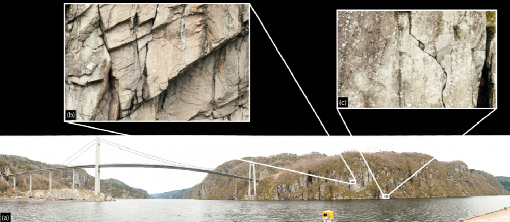
Figure 3.
(a) 1.91 gigapixel image, captured with a Nikon D300s and a 135 mm f2. (b) Gigapixel image zoomed into the natural resolution illustrating fractures contributing to rockfall. (c) Gigapixel image zoomed into the natural resolution illustrating open fractures in the rockmass
Figure 3.
(a) 1.91 gigapixel image, captured with a Nikon D300s and a 135 mm f2. (b) Gigapixel image zoomed into the natural resolution illustrating fractures contributing to rockfall. (c) Gigapixel image zoomed into the natural resolution illustrating open fractures in the rockmass

Figure 4.
Manual Pano-Gimbal head with 400 mm and 2× teleconverter on D7000: effective focal length of 1,200 mm.
Figure 4.
Manual Pano-Gimbal head with 400 mm and 2× teleconverter on D7000: effective focal length of 1,200 mm.

Figure 5.
Overview map and pictures of field sites in Norway in which gigapixel photogrammetry was tested (note scale, coordinates and north arrow apply to background map only).
Figure 5.
Overview map and pictures of field sites in Norway in which gigapixel photogrammetry was tested (note scale, coordinates and north arrow apply to background map only).

Figure 6.
(a) Three-dimensional surface model constructed from the gigapixel imagery collected in Gudvangen, Norway. Original photographic data were collected using a Nikon D3s with a 400 mm f4 lens at a distance of approximately 1,200 m. Red directional lighting (from below) highlights all overhanging surface on the rock face. (b) Zoomed in section of the 3D model illustrating failed rock blocks and the high level of detail in the data. (c) Stereonet plot of discontinuities measured from the 3D mesh, three joint set families are identified.

Figure 7.
(a) Photograph of the site under evaluation in the Rjukan Valley, the planar sliding surface as well as potentially unstable blocks are outlined. (b) Meshed gigapixel photogrammetry data of all data points positioned above the potential planar sliding surface. (c) Stereonet evaluation of the kinematic stability of the highlighted discontinuity with respect to the slope face, indicating instability.


| Site Name | Date of Image Collection | Spectral Space | # of Setup Locations | # of Images Captured | # of Megapixels | Average Base to Distance Ratio |
|---|---|---|---|---|---|---|
| Gudvangen | 13 May 2012 | RGB | 2 | 490 | 5,880 | 1:7 |
| Rjukan | 14 May 2012 | RGB | 3 | 1,164 | 13,968 | 1:4 |
Table 2.
Detailed breakdown of image and 3D data collected at the Gudvangen and Rjukan sites in Norway.
| Site Name | Average Point Cloud Density (pts/m2) | Approx. Average Distance to Object (m) | Posteriori Variance Factor | Average Image RMS |
|---|---|---|---|---|
| Gudvangen | 1,358 | 1,000 | 1.1587 | 0.166 pixels |
| Rjukan | 9,000 | 800 | 0.9273 | 0.168 pixels |
Share and Cite
MDPI and ACS Style
Lato, M.J.; Bevan, G.; Fergusson, M. Gigapixel Imaging and Photogrammetry: Development of a New Long Range Remote Imaging Technique. Remote Sens. 2012, 4, 3006-3021. https://doi.org/10.3390/rs4103006
AMA Style
Lato MJ, Bevan G, Fergusson M. Gigapixel Imaging and Photogrammetry: Development of a New Long Range Remote Imaging Technique. Remote Sensing. 2012; 4(10):3006-3021. https://doi.org/10.3390/rs4103006
Chicago/Turabian StyleLato, Matthew J., George Bevan, and Michael Fergusson. 2012. "Gigapixel Imaging and Photogrammetry: Development of a New Long Range Remote Imaging Technique" Remote Sensing 4, no. 10: 3006-3021. https://doi.org/10.3390/rs4103006