Article

Radar-to-Radar Interference Suppression for Distributed Radar Sensor Networks

School of Communication and Information Engineering, University of Electronic Science and Technology of China, Chengdu 611731, China
*
Author to whom correspondence should be addressed.
Remote Sens. 2014, 6(1), 740-755; https://doi.org/10.3390/rs6010740
Submission received: 17 October 2013 / Revised: 9 December 2013 / Accepted: 24 December 2013 / Published: 9 January 2014

Abstract

:
Radar sensor networks, including bi- and multi-static radars, provide several operational advantages, like reduced vulnerability, good system flexibility and an increased radar cross-section. However, radar-to-radar interference suppression is a major problem in distributed radar sensor networks. In this paper, we present a cross-matched filtering-based radar-to-radar interference suppression algorithm. This algorithm first uses an iterative filtering algorithm to suppress the radar-to-radar interferences and, then, separately matched filtering for each radar. Besides the detailed algorithm derivation, extensive numerical simulation examples are performed with the down-chirp and up-chirp waveforms, partially overlapped or inverse chirp rate linearly frequency modulation (LFM) waveforms and orthogonal frequency division multiplexing (ODFM) chirp diverse waveforms. The effectiveness of the algorithm is verified by the simulation results.

1. Introduction

In recent years, radar sensor networks, including bi- and multi-static radars, have received much attention [17]. In radar sensor networks, each radar can be an independent sensor that transmits a specified waveform and receives the corresponding returns. It also allows multiple passive receivers, operating at a close range, to receive the signals reflected from potentially hostile areas. These passive receivers may be teamed with the transmitters placed at a safe distance or they may make use of opportunistic illuminators, such as television and radio transmitters or, even, over-passing satellites [8]. All the radars can work cooperatively to obtain an improved performance [9]. They can be arranged to survey a large area and observe targets from different angles. For example, the radar sensor network that works in an ad hoc fashion, but is grouped together by an intelligent cluster-head was proposed in [10]. Moreover, radar sensor networks offer a potential to alleviate the blind speed problem that occurs when the Doppler frequency shift is equal to the same or a multiple of the pulse repetition frequency (PRF) [11].
However, besides the time, phase and antenna synchronization [12,13], radar-to-radar interference is a major problem in radar sensor networks [14], especially when two or more radars are concurrently operating in the same frequency band and, thereby, mutually interfering each another [15]. The occurrence of radar-to-radar interference is dictated by the radars operating within some given region juxtaposed against the available spectrum within which these radars may transmit. If operated in a cooperative manner, the collection of proximate radars may avoid the most severe interference condition, whereby one radar directly illuminates another. However, the accumulation of interferences from direct-path reflections and transmitter-receiver antenna sidelobe interaction can still yield significant sensitivity degradation from other in-band and near-band radars.
There exists several interference suppression methods that are reported to have good performance [1622], but each has some limitations or drawbacks. An intuitive method is to shift the radar carrier frequency to a frequency range that is not contaminated by the radar-to-radar interferences. However, this practice has a problem in that it is usually difficult to find a free band with sufficient bandwidth to operate for distributed radar sensor networks. An interference suppression algorithm was proposed in [23] to remove all the signals, except for the interference, similar to switching off the transmitter, for subtraction from the original radar signal. This algorithm has the limitation that the peaks must be separated from, or at least not totally occupied by, the interference. Additionally, several other methods in the time or frequency domain have been proposed to mitigate RF (radio frequency) interference in radar and radio systems, e.g., the time-frequency blanking [24], reconstructing and then subtracting [25] and range domain orthogonal projection filtering [16]. Particularly, a multistatic adaptive pulse compression algorithm was proposed in [26] to separate concurrently received radar signals within the same frequency band given the knowledge of the individual radar waveforms. This algorithm is based on a recursive implementation of a minimum mean-square error formulation. An adaptive receive filter is estimated for each resolution cell of each received radar signal by utilizing the estimated values of the contemporaneous resolution cells. Although these methods work well for sinusoidal interferences, they are not suitable for dealing with wideband or nonstationary interferences, particularly wideband radar-to-radar interferences that typically occur in distributed radar sensor networks.
An amplitude limiting algorithm is proposed in [27] to suppress the mutual interferences of the other waveforms, but how to choose the limiting threshold is not provided [28]. Moreover, only the basic up-chirp and down-chirp waveforms are considered. This paper extends this to suppress wideband radar-to-radar interferences in distributed radar sensor networks with an adaptive decision threshold. This algorithm uses first an iterative filtering algorithm to suppress the radar-to-radar interferences and then a separately matched filtering for each radar. Furthermore, the interference cancellation ratio is also investigated. The remaining sections are organized as follows. Section 2 presents the radar-to-radar interference suppression algorithm. Next, extensive numerical simulation examples and results are provided in Section 3. Finally, this paper is concluded in Section 4 with a short discussion of some other potential applications.

2. Radar-to-Radar Interference Suppression

As shown in Figure 1, the signals received by each radar are comprised of the returned signals originating from multiple concurrently transmitting radars. Note that no synchronicity can be assumed for the multiple transmitting radars, as they do not need to be cooperative for some applications (the synchronization problem is out of the scope of this paper and can be found in our previous work [12]). Without loss of generality, we assume that the illuminated scatterers and radar platforms have no excessively disparate velocities (relative to the operating center frequency and respective time-bandwidth products), such that the Doppler spread over the temporal extent of a reflected bistatic waveform is negligible. For applications in which the Doppler effects on the respective bistatic waveforms cannot be ignored, Doppler-shifted versions of the nominal bistatic waveforms will be employed in the processing framework as additional received waveforms.

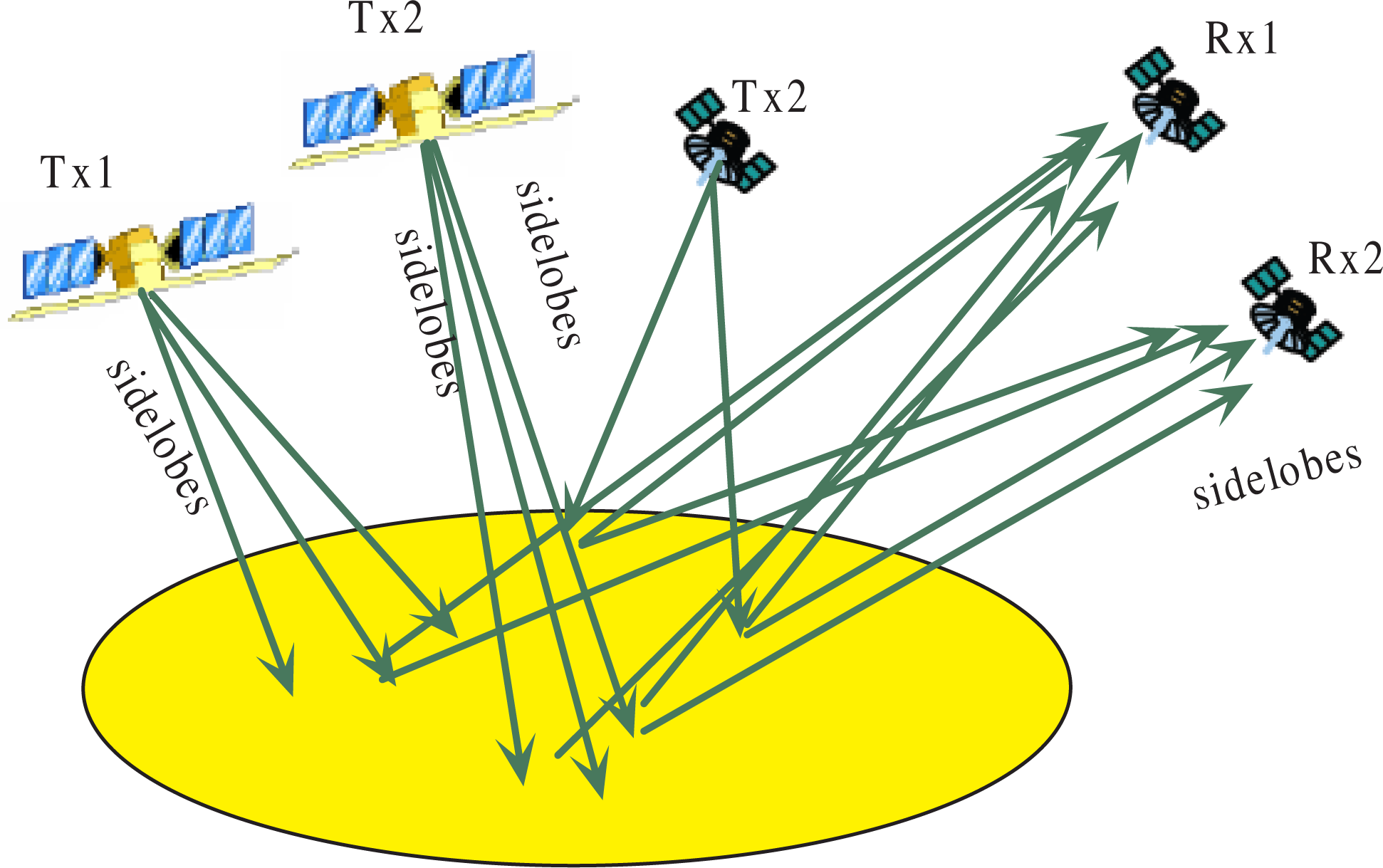
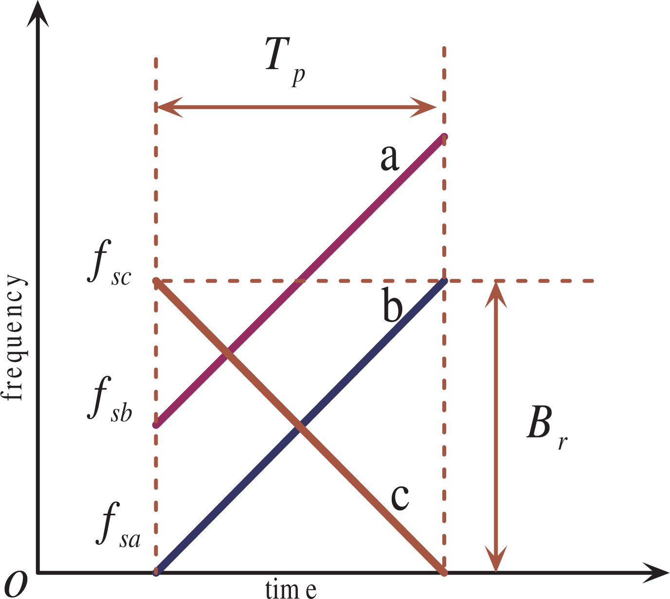
2.1. Radar-to-Radar Interference

Although directional beamforming can be steered towards the direction of the desired signal to reduce interferences, the desired radar will receive other radars’ returns from its antenna main beam and sidelobes. The signals received by the n-th radar receiver can be represented by:
x n ( t ) = m = 1 M α m , n s m ( t τ m , n ) + n ( t )
where m ∈ [1, 2, 3,..., M] and n ∈ [1, 2, 3,..., N], with M and N being the number of the transmitting and receiving radars, sm(t) is waveform transmitted by the m-th transmitting radar, αm,n is the channel coefficient for the m-th transmitting radar and the n-th receiving radar, τm,n is the time for the signal propagating from the m-th transmitting antenna to the n-th receiving antenna and n(t) is the additive noise (no statistical assumptions are made on the characteristics of the noise at this time other than being independent of the radar returns).
In typical radars, the overlapped returns expressed in Equation (1) must be extracted separately for subsequent radar signal processing. Without loss of generality, we denote m = 1 as the index corresponding to the desired signal that we want to extract. Matched filtering with the reference function h 1 ( t ) = s 1 * ( t ) with * being the conjugate operator to extract the returns associated with the first radar signal, s1(t), in the n-th radar:
y n ( t ) = x n ( t ) h 1 ( t ) = α 1 , n s 1 ( t τ 1 , n ) h 1 ( t ) + m = 2 M α m , n s m ( t τ m , n ) h 1 ( t ) + n ( t ) h 1 ( t )
where ⊗ is the convolution operator. α1,ns1(tτ1,n) ⊗ h1(t) is the desired matched filtering output, n(t)⊗h1(t) is the unavoidable output associated with various system noise and m = 2 M α m , n s m ( t τ m , n ) h 1 ( t ) is just the radar-to-radar interferences that we want to suppress in this paper.
If the waveforms used in the radar sensor network are perfectly orthogonal, then:
m = 2 M α m , n s m ( t τ m , n ) h 1 ( t ) = 0
That is to say, in this case, there will be no radar-to-radar interferences in the radar sensor networks. A typical orthogonal waveform is the Barker code [29]; however, Barker code-based waveforms have only a single carrier frequency, and consequently, they have low practicability in actual radar systems. Although waveform diversity design for multiple-input and multiple-output (MIMO) radars has received much attention in recent years [3032], their performance is based primarily on a waveform orthogonality assumption [33]. However, perfect waveform orthogonality cannot be implemented in actual radar sensor networks, and thus, we must develop some algorithms to suppress the radar-to-radar interferences. In [32], we presented the chirp diverse waveform for MIMOSARremote sensing, but we used only the simple matched filtering method to extract the desired returns without considering the mutual interferences.

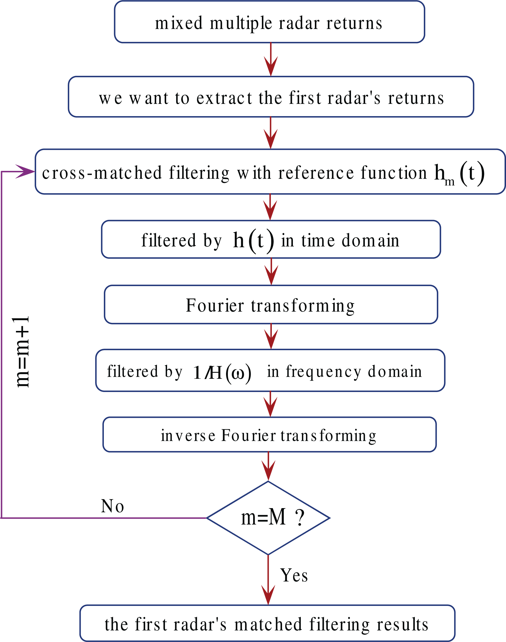
2.2. Iterative Suppression Algorithm

In distributed radar sensor networks, a conventional matched filtering algorithm may be significantly impacted by the radar-to-radar interferences, due to imperfect waveform orthogonality. To resolve this problem, we present an iterative suppression algorithm based on the cross-filtering idea discussed in [27]. In the following, we assume the transmitted waveforms either occupy the same frequency band or the receiver bandwidth is large enough to receive any of the bistatic radar returns that only partially coincide with the frequency band allocated to other radars in the sensor networks.
For simplicity and without loss of generality, the additive noise, namely n(t) expressed in Equation (1), is ignored in the following discussions. The signals received by the n-th radar receiver can then be expressed as:
x n ( t ) = m = 1 M α m , n s m ( t τ m , n )
We denote m = 1 and n = 1 as the index corresponding to the desired monostatic radar pair using the first radar as the transmitter and receiver. To extract this desired radar return associated with s1(t) from the mixed multiple radar returns, we firstly match filtered the returns to the second radar signal, s2(t):
y 1 , 2 ( t ) = [ m = 1 M α m , 1 s m ( t τ m , 1 ) ] h 2 ( t ) = α 2 , 1 s 2 ( t τ 2 , 1 ) h 2 ( t ) + m = 1 , m 2 M α m , 1 s m ( t τ m , 1 ) h 2 ( t )
where h 2 ( t ) = s 2 * ( t ) is the reference function corresponding to the second radar signal, s2(t). Obviously, the first term α2,1 s2(tτ2,1) ⊗ h2(t) will have peaks, because it is the matched filtering results associated with the second radar signal, s2(t), and the remaining terms are the interferences coming from other radars.
The interferences can be removed by a specific filter, the impulse response function, h(t), of which is defined as:
y ( t ) = h ( t ) x ( t ) = { 0 , if | x ( t ) | δ x ( t ) , otherwise
where x(t) denotes the filter input signal, y(t) denotes the filter output signal and δ denotes the decision threshold. The impulse response, h(t), will vary with the change of the input, x(t). If the input, x(t), namely the matched filtering result, y1,2(t), is greater than the decision threshold, δ, the signal components that are greater than the threshold will be equal to zero. That is to say, we do not need to know the expression of the impulse response, h(t). Therefore, it is not necessary to derive the impulse response function, h(t). The selection of the decision threshold, δ, is conceptually similar to that of stop-band attention in the classic bandpass filter design [34]. In this paper, the decision threshold is adaptively determined by the mean of the matched filtering output. That is:
δ = 𝔼 { y 1 , 2 ( t ) }
where 𝔼 {·} is to calculate the average.
Using this specific filter, we can get:
y 1 , 2 f ( t ) = y 1 , 2 ( t ) h ( t ) = α 1 , 1 s 1 ( t τ 1 , 1 ) h 2 ( t ) + m = 3 M α m , 1 s m ( t τ m , 1 ) h 2 ( t )
This equation just mathematically explains the amplitude-limited filtering algorithm, and we do not need to know h(t), because we easily can make the amplitudes of the signal components that are greater than the decision threshold equal to zero.
Fourier transforming with respect to the variable, t, yields:
Y 1 , 2 f ( ω ) = α 1 , 1 S 1 ( ω ω 1 , 1 ) H 2 ( ω ) + m = 3 M α m , 1 S m ( ω ω m , 1 ) H 2 ( ω )
where Y1,2f (ω), S1(ωω1,1), H2(ω) and Sm(ωωm,1) denote, respectively, the Fourier transforming representations of the Y1,2f (t), s1(tτ1,1), h2(t) and sm(tτm,1), with ω1,1 and ωm,1 being the frequency shifts associated with the time shifts, τ1,1 and τ3,1. The above equation can be further filtered by an inverse filter in the frequency domain with the transfer function, 1/H2(ω)[27]:
Y 1 , 2 i ( ω ) = Y 1 , 2 f ( ω ) 1 H 2 ( ω ) = ˙ α 1 , 1 S 1 ( ω ω 1 , 1 ) + m = 3 M α m , 1 S m ( ω ω m , 1 )
Applying an inverse Fourier transforming to Equation (10) yields:
y 1 , 2 i ( t ) = α 1 , 1 s 1 ( t τ 1 , 1 ) + m = 3 M α m , 1 s m ( t τ m , 1 )
It can be noticed that the interferences of the second radar corresponding to the second transmitted waveform, s2(t), have been suppressed at this step.
In the same manner, we further match filtered y1,2i(t) to the third radar signal, s3(t):
y 1 , 2 3 ( t ) = y 1 , 2 i ( t ) h 3 ( t ) = α 1 , 1 s 1 ( t τ 1 , 1 ) h 3 ( t ) + α 3 , 1 s 3 ( t τ 3 , 1 ) h 3 ( t ) + m = 4 M α m , 1 s m ( t τ m , 1 ) h 3 ( t )
where h 3 ( t ) = s 3 * ( t ) is the reference function corresponding to the third radar signal, s3(t). Similarly, the second term can be removed by the specific filter, h(t):
y 1 , 2 3 f ( t ) = y 1 , 2 3 ( t ) h ( t ) = α 1 , 1 s 1 ( t τ 1 , 1 ) h 3 ( t ) + m = 4 M α m , 1 s m ( t τ m , 1 ) h 3 ( t )
Fourier transforming with respect to the variable, t, yields:
Y 1 , 2 3 f ( ω ) = α 1 , 1 S 1 ( ω ω 1 , 1 ) S 3 * ( ω ) + m = 4 M α m , 1 S m ( ω ω m , 1 ) H 3 ( ω )
where H3(ω) is the Fourier transforming representation of h3(t).
It is further filtered by a filter in the frequency domain with the transfer function, 1/H3(ω):
Y 1 , 2 3 i ( ω ) = Y 1 , 2 f ( ω ) 1 H 3 ( ω ) = ˙ α 1 , 1 S 1 ( ω ω 1 , 1 ) + m = 4 M α m , 1 S m ( ω ω m , 1 )
After applying an inverse Fourier transform, we then have:
y 1 , 2 3 i ( t ) = α 1 , 1 s 1 ( t τ 1 , 1 ) + m = 4 M α m , 1 s m ( t τ m , 1 )
It can be noticed that the interferences of the second and third radars corresponding to the second and third transmitted waveforms have been suppressed at this step. The remaining interferences associated with other radars can be suppressed by iteratively applying the above suppression algorithm. In doing so, we then have:
y 1 , 2 4 i ( t ) = α 1 , 1 s 1 ( t τ 1 , 1 ) + m = 5 M α m , 1 s m ( t τ m , 1 )
y 1 , 2 5 i ( t ) = α 1 , 1 s 1 ( t τ 1 , 1 ) + m = 6 M α m , 1 s m ( t τ m , 1 )
. . . . . . . . . . . . . . . . . . . . . . . . . . . . . . . . . . . . . . . . . . . . .
y 1 , 2 ( M 2 ) i ( t ) = α 1 , 1 s 1 ( t τ 1 , 1 ) + m = ( M 1 ) M α m , 1 s m ( t τ m , 1 )
Therefore, we can obtain the desired returns associated with the first radar as:
y 1 , 2 ( M 1 ) i ( t ) = α 1 , 1 s 1 ( t τ 1 , 1 )
The detailed processing steps of the above suppression algorithm are illustrated in Figure 2.

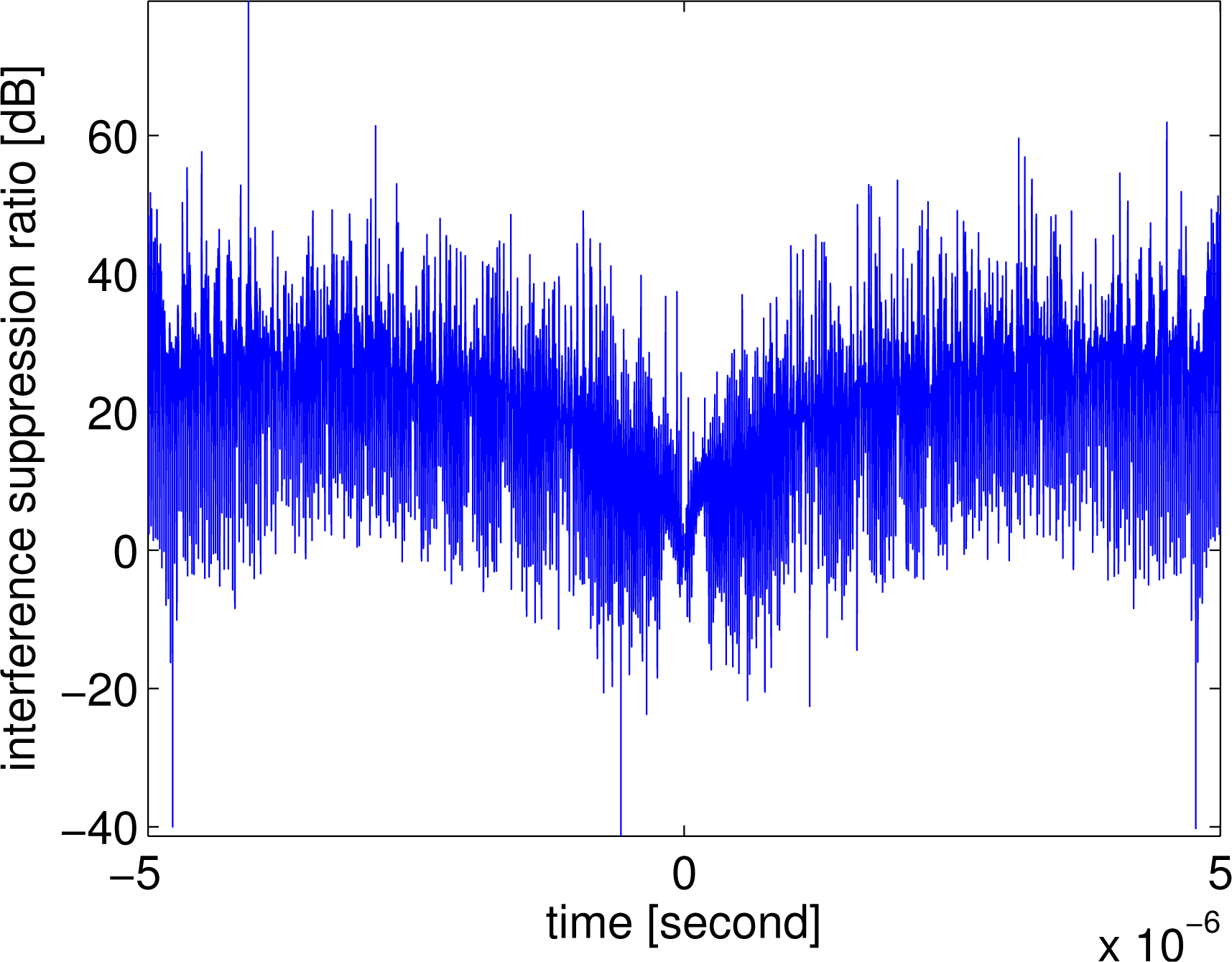
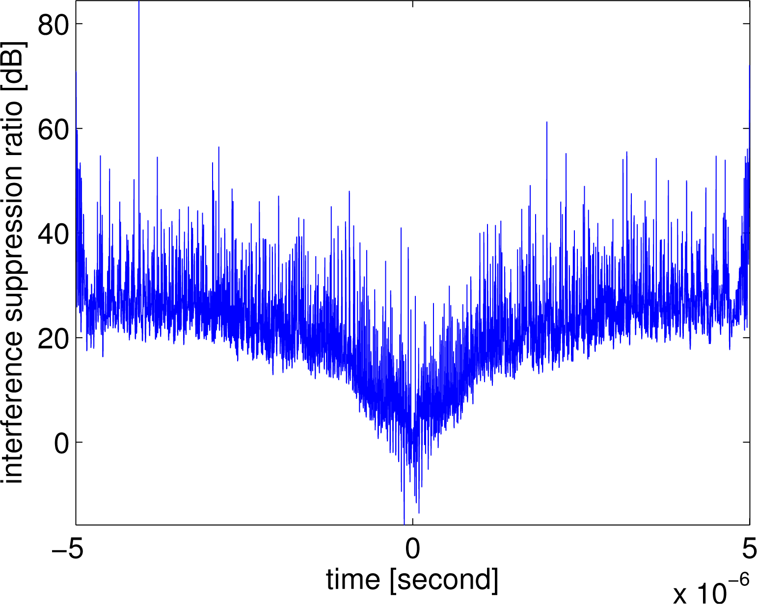
2.3. Interference Suppression Ratio

It is necessary to further investigate the interference suppression performance. Suppose we want to extract the returns associated with the m-th radar signal, sm(t). The corresponding matched filtering result without employing the interference suppression algorithm is:
z without m ( t ) = [ m = 1 M α m , 1 s m ( t τ m , 1 ) ] h m ( t )
where hm(t) is the matched filtering reference function for the first radar signal, sm(t). In contrast, when the interference suppression method is employed, according to (17) and (18), the final matched filtering result for the first radar will be:
z with m ( t ) = y m , 2 ( M 1 ) i ( t )
Therefore, the suppression of the radar-to-radar interference can then be evaluated by the interference suppression ratio (ISR) defined as:
ISR m = z without m ( t ) z with m ( t )

3. Numerical Simulation Examples

To evaluate the quantitative performance of the radar-to-radar interference suppression algorithm for distributed radar sensor networks, we performed several numerical simulations with different radar waveforms.

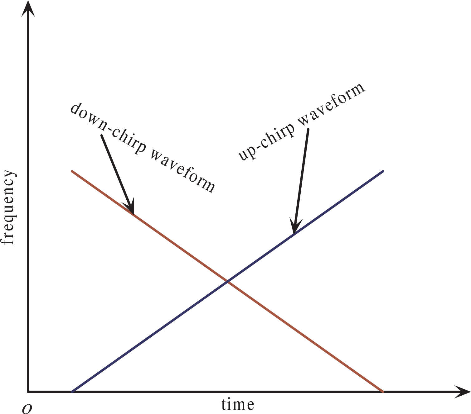
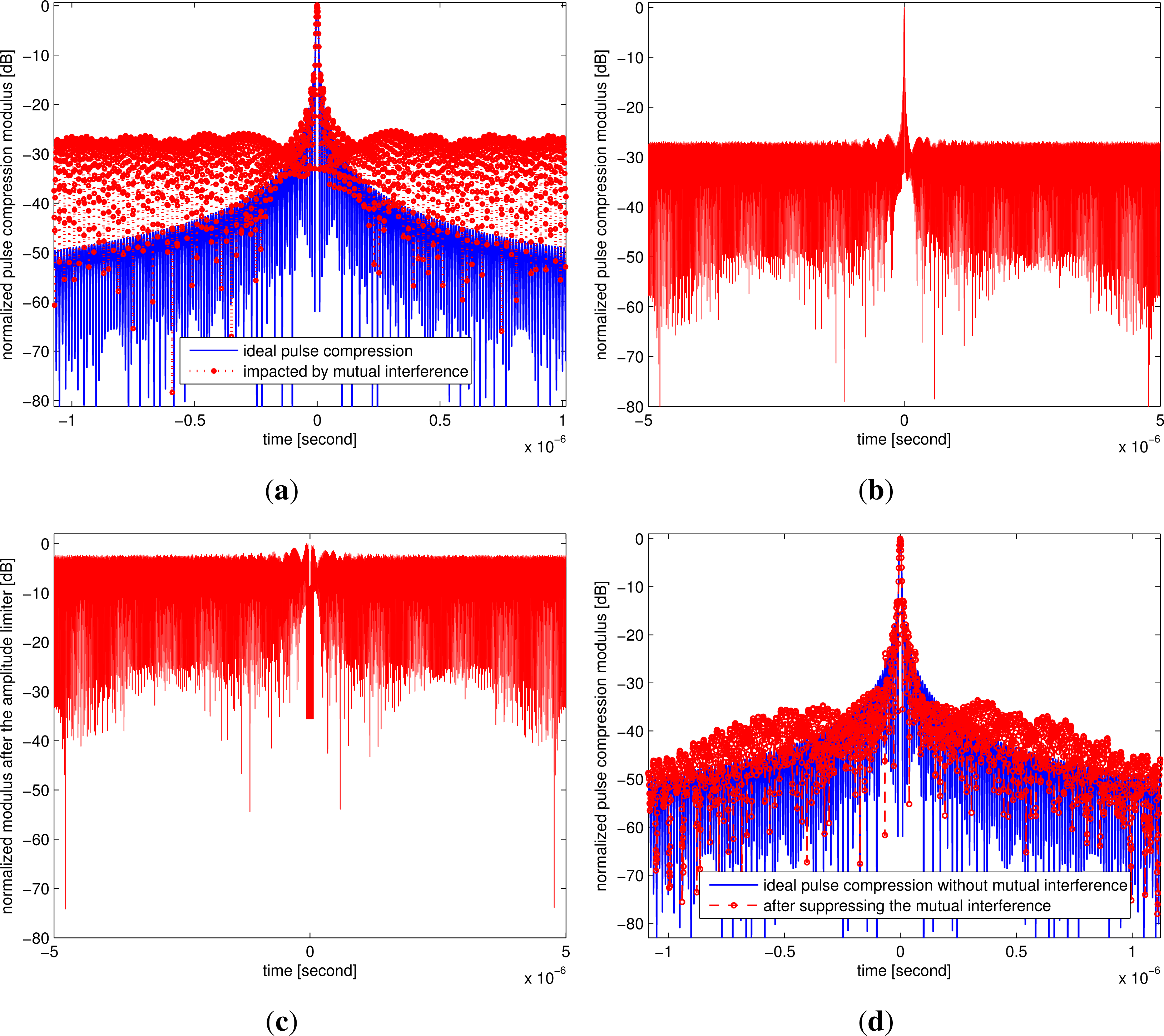
Example 1: Two Radars Using the Down-Chirp and Up-Chirp Waveforms

To reduce radar-to-radar interferences, each radar in the distributed radar sensor networks should transmit a unique waveform, orthogonal to the waveforms transmitted by other radars. We simulate first the down-chirp and up-chirp waveforms, which are the most practical orthogonal waveforms in radar society. Suppose the two radars in the network use, respectively, the down-chirp and up-chirp waveforms (see Figure 3) with the following parameters: fs1 = 100 MHz, fs2 = 0 Hz, equal chirp bandwidth Br = 100 MHz and equal chirp duration Tp = 10 μs. Figure 4 shows the comparative pulse compression processing results, where we want to extract the first radar’s returns and suppress the mutual interference of the second radar. It can be noticed that the radar-to-radar interferences have been significantly suppressed by the interference suppression algorithm. Figure 5 gives the simulated interference suppression ratio. The interference levels have been suppressed at least by 20 dB. This improvement factor is important for detecting weak targets; otherwise, some weak targets will be submerged in the sidelobes and cannot be successfully detected by the radar processor.

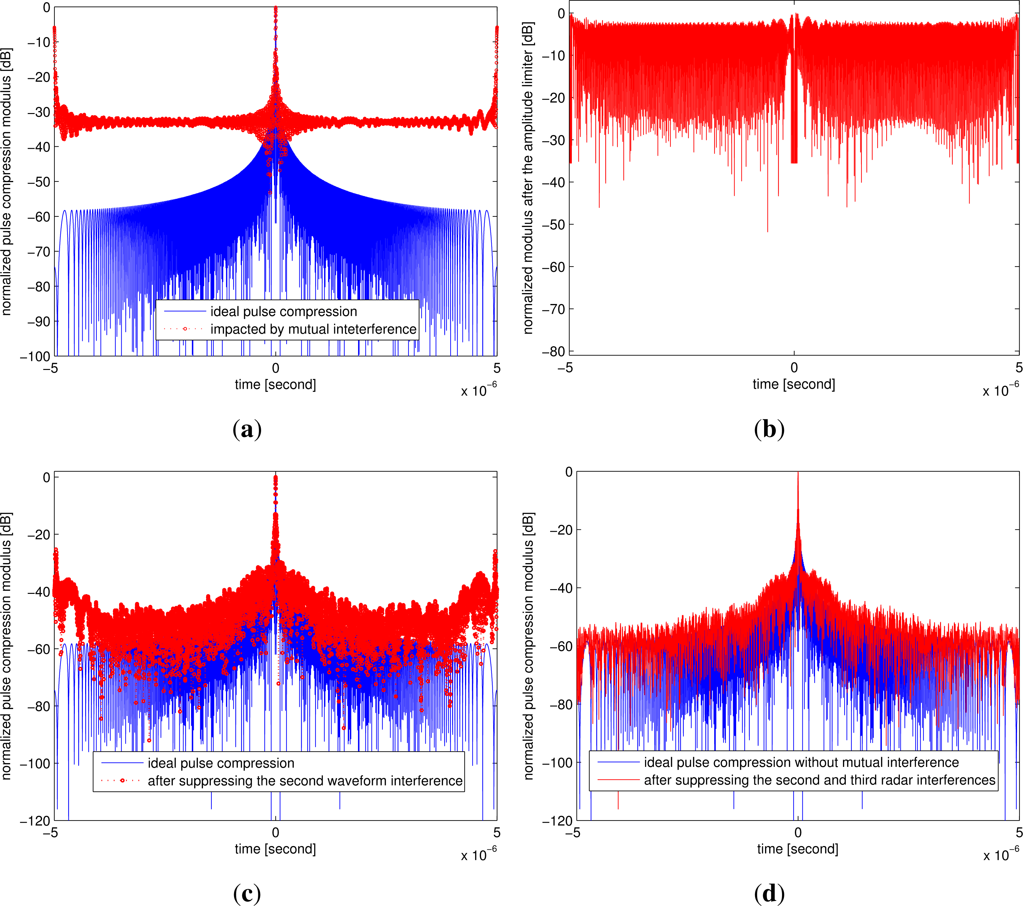
Example 2: Three Radars Using the Partially Overlapped or Inverse Chirp Rate Waveforms

Although the down-chirp and up-chirp waveforms have good orthogonality, they offer only two orthogonal waveforms. We concluded in [35] that the chirp waveforms with an adjacent starting frequency and inverse chirp rate provide also a good mutual interference suppression performance. However, using an adjacent starting frequency means a wider total RF bandwidth and larger complexity for the radar hardware system. From a practical point of view, we think that a practical radar should use the chirp waveforms with equal chirp duration and an equal absolute chirp rate, so as to reduce the hardware system design complexity. For these reasons, we assume that three radars in the network use, respectively, the three waveforms (a, b and c) given in Figure 6.
Consider the following parameters: fs1 = 50 MHz, fs2 = 0 Hz, fs3 = 100 MHz, equal chirp bandwidth Br = 100 MHz and equal chirp duration Tp = 10 μs; Figure 7 shows the comparative pulse compression results, where we want to extract the first radar’s returns. The returns associated with the second and third signals are undesired radar-to-radar interferences. It can be noticed from Figure 7a that there are unacceptable large sidelobes due to the interferences coming from the second and third radars. After suppressing the second radar signals with the proposed algorithm, it can be noticed from Figure 7c that the sidelobes are significantly reduced, but there still are high sidelobes in the two sides. It can be noticed from Figure 7d that these high sidelobes are further reduced after suppressing the mutual interferences associated with the third radar. It can be noticed from the interference suppression ratio shown in Figure 8 that the mutual interferences have been suppressed by about 20 dB.

Example 3: Two Radars Using the OFDM Chirp Waveforms

Orthogonal frequency division multiplexing (OFDM) is also a popular choice for distributed radar sensor networks, because OFDM offers advantages, such as robustness against multipath fading and relatively simple synchronization processing. OFDM-like waveforms have been shown to be suitable for radar applications [36,37] and the feasibility of integrating communication functions in radar networks have also been explored in [38]. It has been proven in [39] that OFDM-coded radar waveforms are comparable with linearly frequency modulation (LFM) waveforms and, furthermore, experience no range-Doppler coupling. Therefore, we simulated the mutual interference suppression algorithm for two radars using the OFDM chirp diverse waveforms designed in [40]. As shown in Figure 9, the two OFDM chirp diverse waveforms have the following parameters: 16 subcarriers, 16 chips; the subcarrier bandwidth is 10 MHz, and the chip duration is 1 μs.
Figures 10 and 11 show the comparative pulse compression and interference suppression ratio results, respectively. It can be noticed that, although the OFDM chirp waveforms have good orthogonality, the interference sidelobes can be further reduced by applying the radar-to-radar interference suppression algorithm. This method is also suited for noise radars [41], which can be processed in the same way.

4. Conclusions

Due to the operational advantages, like reduced vulnerability, good system flexibility and increased radar cross-section, distributed radar sensor networks have received much attention in recent years. However, radar-to-radar interference is a major problem in radar sensor networks. In this paper, we propose an iterative radar-to-radar interference suppression algorithm based on the cross-matched filtering for distributed radar sensor networks. After analyzing the impacts of radar-to-radar interferences in distributed radar sensor networks, we derived the radar-to-radar interference suppression algorithm. This algorithm can be iteratively processed to suppress the radar-to-radar interferences one by one. We performed extensive numerical simulations with different waveforms that can be used in distributed radar sensor networks, such as down-chirp and up-chirp waveforms, the partially overlapped or inverse chirp rate LFM waveform and the OFDM chirp diverse waveform. The effectiveness of the proposed suppression algorithm is verified by simulation results. Note that the suppression algorithm is also suitable for other waveforms, e.g., polyphase code and noise waveform, not just the waveforms discussed in this paper, because no specific assumptions on the waveforms are assumed in deriving the algorithm.

Acknowledgments

This work was supported in part by the National Natural Science Foundation of China under grant No. 41101317, the Program for New Century Excellent Talents in University under grant No. NCET-12-0095, the Program for Distinguished Young Scholars in Sichuan Province under grant No. 2013JQ0003 and the Program for Young Scholars of Distinction of UESTC.

Author Contributions

The authors have equal contributions to this paper.

Conflicts of Interest

The authors declare no conflicts of interest.

References

  1. Arik, M.; Akan, O. Collaborative mobile target imaging in UWB wireless radar sensor networks. IEEE J. Sel. Areas Commun 2010, 28, 950–961. [Google Scholar]
  2. Antonio, P.; Grimaccia, F.; Mussetta, M. Architecture and methods for innovative heterogeneous wireless sensor network applications. Remote Sens 2012, 4, 1146–1161. [Google Scholar]
  3. Qiao, G.; Lu, P.; Scaioni, M.; Xu, S.Y.; Tong, X.H.; Feng, T.T.; Wu, H.B.; Chen, W.; Tian, Y.X.; Wang, W.A.; et al. Landslide investigation with remote sensing and sensor network: From susceptibility mapping and scaled-down simulation towards in situ sensor network design. Remote Sens 2013, 5, 4319–4346. [Google Scholar]
  4. Liang, Q.L. Radar sensor wireless channel modeling in Foliage environment: UWB versus narrowband. IEEE Sens. J 2011, 11, 1448–1457. [Google Scholar]
  5. Wang, W.Q. Distributed passive radar sensor networks with near-space vehicle-borne receivers. IET Wirel. Sens. Syst 2012, 2, 183–190. [Google Scholar]
  6. Ouchi, K. Recent trend and advance of synthetic aperture radar with selected topics. Remote Sens 2013, 5, 716–807. [Google Scholar]
  7. Xu, L.; Liang, Q.L. Radar sensor network using a set of ternary codes: Theory and application. IEEE Sens. J 2011, 11, 439–450. [Google Scholar]
  8. Krieger, G.; Moreira, A. Spaceborne bi- and multistatic SAR: Potential and challenges. IEE Proc. Radar Sonar Navig 2006, 153, 184–198. [Google Scholar]
  9. Hume, A.L.; Baker, C.J. Netted Radar Sensing. Proceedings of the IEEE Radar Conference, Beijing, China, 15–18 October 2001; pp. 23–26.
  10. Liang, J.; Liang, Q. Design and analysis of distributed radar sensor networks. IEEE Trans. Parallel Distrib. Syst 2011, 22, 1926–1933. [Google Scholar]
  11. Liang, Q. Radar Sensor Networks for Automatic Target Recognition with Delay-Doppler Uncertainty. Proceedings of the IEEE Military Communication Conference, Washington, DC, USA, 23–25 October 2006; pp. 1–7.
  12. Wang, W.Q. GPS-based time & phase synchronization processing for distributed SAR. IEEE Trans. Aerosp. Electron. Syst 2009, 45, 1041–1052. [Google Scholar]
  13. Krieger, G.; Younis, M. Impact of oscillator noise in bistatic and multisatic SAR. IEEE Geosci. Remote Sens. Lett 2006, 3, 424–429. [Google Scholar]
  14. Foreman, T.L. A model to quantify the effects of sensitivity time control on radar radar-to-radar interference. IEEE Trans. Electromagn. Compat 1995, 37, 299–301. [Google Scholar]
  15. Brooker, G.M. Mutual interference of millimeter-wave radar systems. IEEE Trans. Electromagn. Compat 2007, 49, 170–181. [Google Scholar]
  16. Zhou, H.; Wen, B.Y.; Wu, S.C. Dense radio frequency interference suppression in HF radars. IEEE Signal Process. Lett 2005, 12, 361–364. [Google Scholar]
  17. Wang, W.; Wyatt, L.R. Radio frequency interference cancellation for sea-state remote sensing by high-frequency radar. IET Radar Sonar Navig 2010, 5, 2085–2099. [Google Scholar]
  18. Anandan, V.K.; Jagannatham, D.B.V. An automomous interference detection and filtering approach applied to wind profilers. IEEE Trans. Geosci. Remote Sens 2010, 48, 1660–1666. [Google Scholar]
  19. Tarongi, J.M.; Camps, A. Normality analysis for RFI detection in microwave radiometry. Remote Sens 2010, 2, 191–210. [Google Scholar]
  20. Elgamel, S.A.; Soraghan, J.J. Using EMD-FrFT filtering to mitigate very high power interference in chirp tracking radars. IEEE Signal Process. Lett 2011, 18, 263–266. [Google Scholar]
  21. Zhou, H.; Wen, B.Y. Radio frequency interference suppression in small-aperture high-frequency radars. IEEE Geosci. Remote Sens. Lett 2012, 9, 788–792. [Google Scholar]
  22. Thayaparan, M.D.T.; Djukanović, S.; Stanković, L.J. Time-frequency-based non-stationary interference suppression for noise radar systems. IET Radar Sonar Navig 2008, 2, 306–314. [Google Scholar]
  23. Gurgel, K.W.; Barbin, Y.; Schlick, T. Radio Frequency Interference Suppression Techniques in FMCW Modulated HF Radars. Proceedings of the IEEE OCEANS Conference, Aberdeen, UK, 18–21 June 2007; pp. 538–541.
  24. Zhou, H.; Wen, B.; Luo, Y. Radio frequency interference suppression in HF radars. Electron. Lett 2003, 39, 925–927. [Google Scholar]
  25. Chen, G.; Wen, B.; Wu, S.; Luo, Y. HF radio-frequency interference mitigation. IEEE Geosci. Remote Sens. Lett 2010, 7, 479–482. [Google Scholar]
  26. Blunt, S.D.; Gerlach, K. Multistatic adaptive pulse compression. IEEE Trans. Aerosp. Electron. Syst 2006, 42, 891–903. [Google Scholar]
  27. Huang, P.P. Method of removing the cross-correlation noise for dual-input and dual-output SAR. J. Radar 2012, 1, 91–95. [Google Scholar]
  28. Meng, C.Z.; Xu, J.; Peng, S.B.; Yang, J.; Wang, X.J.; Peng, P.Y. Suppress Cross-Correlation Noise of Same Frequency Coding Orthogonal Signals in MIMO-SAR. Proceedings of the IET International Radar Conference, Xi’an, China, 14–16 April 2013; pp. 1–6.
  29. Sverdlik, H.B.; Levanon, N. Family of multicarrier bi-phase radar signals represented by ternary arrays. IEEE Trans. Aerosp. Electron. Syst 2006, 42, 933–953. [Google Scholar]
  30. Dai, F.Z.; Liu, H.W.; Wang, P.H.; Xia, S.Z. Adaptive waveform design for range-spread target tracking. Electron. Lett 2010, 46, 793–794. [Google Scholar]
  31. Sen, S.; Nehorai, A. Adaptive OFDM radar for target detection in multipath scenarios. IEEE Trans. Signal Process 2011, 59, 78–90. [Google Scholar]
  32. Wang, W.Q.; Cai, J.Y. MIMO SAR using chirp diverse waveform for wide-swath remote sensing. IEEE Trans. Aerosp. Electron. Syst 2012, 48, 3171–3185. [Google Scholar]
  33. Daum, F.; Huang, J. MIMO radar: Snake oil or good idea. IEEE Aerosp. Electron. Syst. Mag 2009, 24, 8–12. [Google Scholar]
  34. Hassanien, A.; Vorobyov, S.A. Transmit energy focusing for DOA estimation in MIMO radar with colocated antennas. IEEE Trans. Signal Process 2011, 59, 2669–2682. [Google Scholar]
  35. Wang, W.Q.; Peng, Q.C.; Cai, J.Y. Waveform diversity-based millimeter-wave UAV SAR remote sensing. IEEE Trans. Geosci. Remote Sens 2009, 45, 691–700. [Google Scholar]
  36. Levanon, N. Multifrequency complementary phased-coded radar signal. IEE Proc. Radar Sonar Navig 2000, 147, 276–284. [Google Scholar]
  37. Surender, S.C.; Narayanan, R.M. UWB noise-OFDM netted radar: Physical layer design and analysis. IEEE Trans. Aerosp. Electron. Syst 2011, 47, 1380–1400. [Google Scholar]
  38. Garmatyuk, D.; Schuerger, J.; Morton, Y.; Binns, K.; Durbin, M.; Kimani, J. Feasibility Study of a Multi-Carrier Dual-Use Imaging Radar and Communication Systems. Proceedings of the European Radar Conference, Munich, Germany, 10–12 October 2007; pp. 194–197.
  39. Franken, G.; Nikookar, H.; Genderen, P.V. Doppler Tolerance of OFDM-Coded Radar Signals. Proceedings of the European Radar Conference, Manchester, UK, 13–15 September 2006; pp. 108–111.
  40. Wang, W.Q. Mitigating range ambiguities in high PRF SAR with OFDM waveform diversity. IEEE Geosci. Remote Sens. Lett 2013, 10, 101–105. [Google Scholar]
  41. Hall, G.M.; Holder, E.J.; Cohen, S.D.; Gauthier, D.J. Low-Cost Chaotic Radar Design. Proceedings of the XVI Conference on Radar Sensor Technology, Baltimore, MD, USA, 23–25 April 2012; pp. 836112:1–836112:13.
Figure 1. The radar-to-radar interferences in a distributed radar sensor network.
Remotesensing 06 00740f1
Figure 2. Block diagram of the interference suppression algorithm.
Remotesensing 06 00740f2
Figure 3. Illustration of down-chirp and up-chirp waveforms.
Remotesensing 06 00740f3
Figure 4. Comparative pulse compression results for the two radars with down-chirp and up-chirp waveforms. (a) Ideal result and mutual interference; (b) pulse compression using the second waveform as the reference function; (c) after being processed by the iterative suppression algorithm; (d) final matched filtering results for the first radar.
Remotesensing 06 00740f4
Figure 5. Result of the interference suppression ratio.
Remotesensing 06 00740f5
Figure 6. Illustration of three waveforms with overlapped frequency.
Remotesensing 06 00740f6
Figure 7. Comparative pulse compression results for the three radars with partially overlapped frequency or inverse chirp rate waveforms. (a) Ideal result and mutual interference; (b) after being pulse compressed by using the second waveform as the reference function and processed by the specific filter; (c) pulse compression after suppressing the second interference; (d) final matched filtering result for the first radar.
Remotesensing 06 00740f7
Figure 8. Result of the interference suppression ratio.
Remotesensing 06 00740f8
Figure 9. Illustration of orthogonal frequency division multiplexing (OFDM) chirp diverse waveforms.
Remotesensing 06 00740f9
Figure 10. Comparative pulse compression results for two radars using the OFDM chirp diverse waveforms: (a) without applying the mutual interference suppression algorithm; (b) with applying the mutual interference suppression algorithm.
Remotesensing 06 00740f10
Figure 11. Result of the interference suppression ratio.
Remotesensing 06 00740f11

