On-Orbit Geometric Calibration Model and Its Applications for High-Resolution Optical Satellite Imagery

Abstract
: On-orbit geometric calibration is a key technology to guarantee the geometric quality of high-resolution optical satellite imagery. In this paper, we present an approach for the on-orbit geometric calibration of high-resolution optical satellite imagery, focusing on two core problems: constructing an on-orbit geometric calibration model and proposing a robust calculation method. First, a rigorous geometric imaging model is constructed based on the analysis of the major error sources. Second, we construct an on-orbit geometric calibration model through performing reasonable optimizing and parameter selection of the rigorous geometric imaging model. On this basis, the calibration parameters are partially calculated with a stepwise iterative method by dividing them into two groups: external and internal calibration parameters. Furthermore, to verify the effectiveness of the proposed calibration model and methodology, on-orbit geometric calibration experiments for ZY1-02C panchromatic camera and ZY-3 three-line array camera are conducted using the reference data of the Songshan calibration test site located in the Henan Province, China. The experimental results demonstrate a certain deviation of the on-orbit calibration result from the initial design values of the calibration parameters. Therefore, on-orbit geometric calibration is necessary for optical satellite imagery. On the other hand, by choosing multiple images, which cover different areas and are acquired at different points in time to verify their geometric accuracy before and after calibration, we find that after on-orbit geometric calibration, the geometric accuracy of these images without ground control points is significantly improved. Additionally, due to the effective elimination of the internal distortion of the camera, greater geometric accuracy was achieved with less ground control points than before calibration.
1. General Instructions
On-orbit geometric calibration is critical to realizing full performance of high-resolution optical remote sensing satellite geometry in subsequent processes and applications [1]. Systematic on-orbit geometric calibrations have been developed for optical remote sensing satellites owned by countries that are more advanced in the space field, such as Europe and America. For RapidEye, the static camera alignment angles are determined accurately by observing the ground control points (GCP)-derived alignments of the satellite over an ensemble of images to average down the scene-dependent random errors introduced by inaccuracy in star track measurements. The camera optical distortion calibration is performed by using hundreds of pseudo-GCP generated by matching the satellite images with the reference orthophotos and corresponding digital elevation model (DEM), however, the detailed camera distortion model is not presented [2]. Only a brief statement on the on-orbit calibration of Pleiades and Orb-view is presented, while some core problems including the geometric calibration model and the calculation method are not concerned [3–5]. After on-orbit geometric calibration, without ground control points the planimetric and elevation accuracy of SPOT-5’s stereo imagery is up to 50 m and 15 m, respectively (RMS) [6,7], while those of IKONOS’s stereo imagery are up to 12 m and 10 m, respectively (RMS) [8,9]. Multiple scholars and research institutions have conducted systematic and comprehensive on-orbit geometric calibrations for the panchromatic camera PRISM equipped on the ALOS satellite [10–12]. A systematic on-orbit calibration is conducted for ALOS PRISM, including the exterior orientation, interior charge coupled devices (CCD) alignment, and sensor-alignment trend calibration. An analysis of the digital surface model derived from these calibration results is also made [13]. Through self-calibration of the PRSIM with a rigorous sensor model, sub-pixel geometric accuracy can be achieved [14]. Via on-orbit geometric calibration, the interior geometric distortion error in each band of imagery from the LISS-4 camera of IRS-P6 has been eliminated. Automated on-ground co-registration of sub-pixel accuracy from multiple bands without image matching has been achieved [1,15].
Due to the rapid growth in the number of satellites in China, the improvement of geometric resolution, the radiometric quality, and increasingly wide range of applications, users demand a better geometric quality of the image product. In particular, China’s first three-line array stereo-mapping satellite—ZY-3 satellite—was successfully launched, which has filled the gap in China’s civilian mapping satellites and serves as a milestone in enhancing China’s independent access to high-resolution geospatial information [16]. To a great extent, the performance and potential of the high-resolution optical satellite imagery depends on its geometric quality. Thus, it is urgent for China to build independent geometric calibration test sites, to conduct robust research in theory, and develop reliable on-orbit geometric calibration techniques. In response, a few test sites for on-orbit calibration for Chinese autonomous remote sensing satellite have been established, among them the Songshan Calibration Test Site was set up as a model. Moreover, Wuhan University and Satellite Surveying and Mapping Application Center (SASMAC) carried out theoretical studies underlying on-orbit geometric calibrations and have achieved successful practical applications for ZY1-02C and ZY-3 [17–21].
Although previous studies have made progress in optical satellite on-orbit geometric calibration to a certain extent, some key scientific problems remain unsolved. In this paper, we discuss in detail the related theory and method of optical satellite on-orbit geometric calibration. First, the sources of major error are sought and a rigorous geometric imaging model is built for optical satellite images. Secondly, through performing a reasonable optimizing and parameter selection of the rigorous geometric imaging model, we build an on-orbit geometric calibration model and study the corresponding calculation method of the calibration parameters. Finally, an on-orbit geometric calibration experiment is performed and verified for ZY1-02C panchromatic camera and ZY-3 three-line array camera with the reference data offered by the Songshan calibration test site. Our proposed calibration model and calculation method has been proven to be stable and effective and could significantly improve the geometric accuracy of optical satellite imagery.
2. Geometric Calibration Model and the Method of Calculation
2.1. Rigorous Geometric Imaging Model
Establishment of a rigorous geometric imaging model is the first step of on-orbit geometric calibration for optical satellite imagery [22,23]. To build a rigorous geometric imaging model, the accurate internal and external orientation parameters of the camera at the moment of imaging are necessary. With the aid of the devices for attitude and position determination, such as GPS receivers, star sensors, and gyros, the external orientation parameters can be acquired. However, due to the limitations in the installation technology and the change of the satellite structure during launching and orbiting, a certain amount of system error always exists between the true value and initial design value of the installation parameters of the camera, which is called “external installation error”; and the error would seriously affect the geometric positioning accuracy of the satellite imagery. In addition, there is a measurement error in the external orientation parameters observed by GPS receiver, star sensors and gyros, which is called “external measurement error”. Although we could perform a laboratory calibration precisely for the camera’s internal orientation parameters before launching, some inevitable factors, such as the changing of the circumstances in space and the aging of the devices, would result in a certain degree of deviation in the internal orientation parameters of the camera during orbiting, which causes the internal systematic distortion of images. Therefore, we should make an analysis of the above-described major errors and build the corresponding mathematic model to eliminate them, and then construct the rigorous geometric imaging model of the optical satellite imagery.
2.1.1. Camera Installation Angle
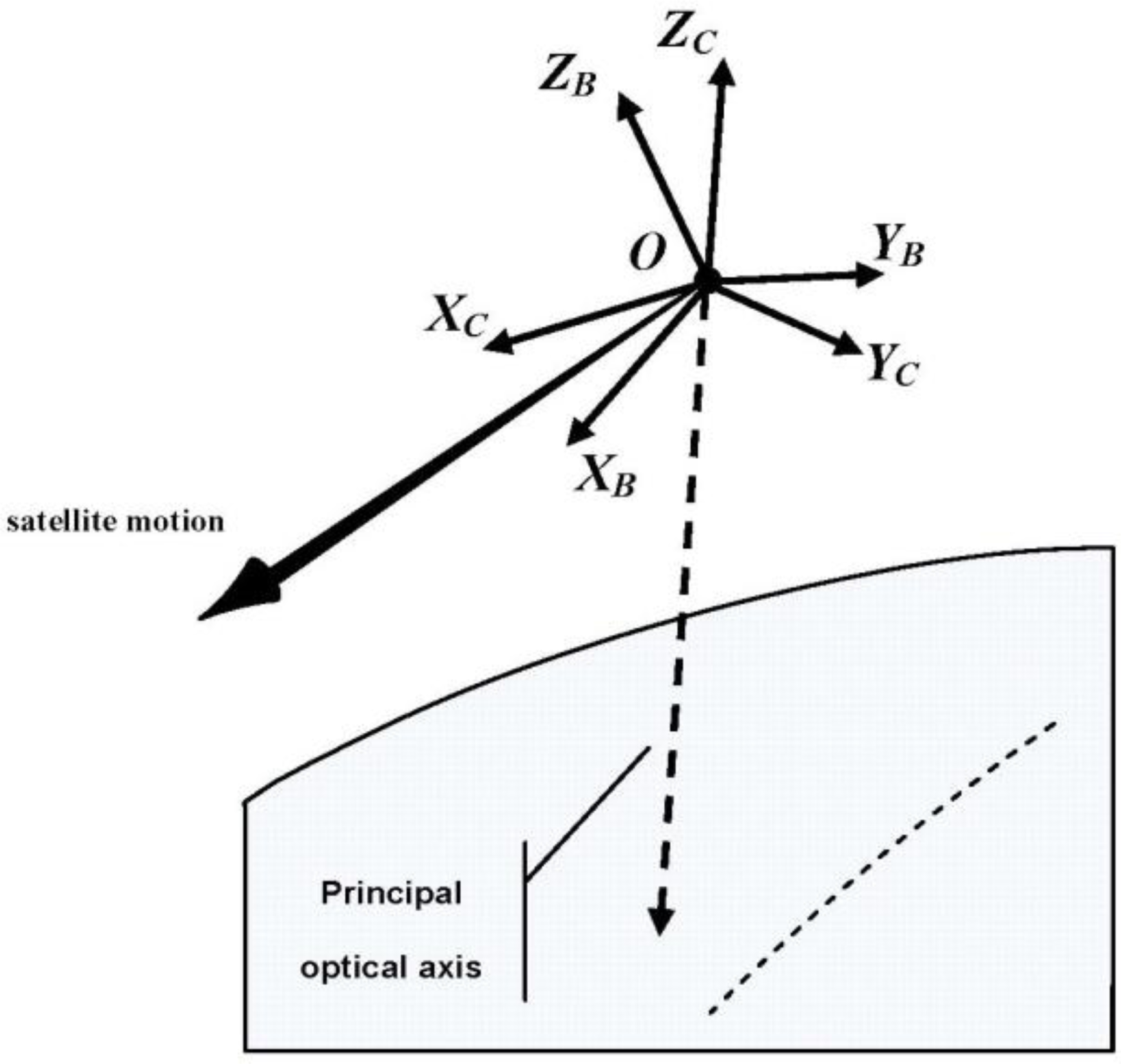
The attitude data observed by attitude determination devices, such as star tracker and gyro, is the rotation angle between the satellite’s body-fixed coordinate system and the inertial spatial coordinate system. Normally an angle bias is designed between the satellite’s body-fixed coordinate system and the camera coordinate system, which is called “Camera installation angle”. In order to determine the attitude of the camera in the inertial spatial coordinate system, an accurate camera installation angle in the satellite’s body-fixed coordinate system is necessary. As shown in Figure 1, O-XCYCZC and O-XBYBZB represent the camera’s coordinate system and the satellite’s body-fixed coordinate system, respectively. Limited in the assembly technology and affected by possible displacement during launch and orbiting, the true camera installation angle is always deviated from its preset one. To solve this problem, a rotation matrix between O-XCYCZC and O-XBYBZB is introduced, accounting for the installation angle.
2.1.2. GPS Eccentric Vector
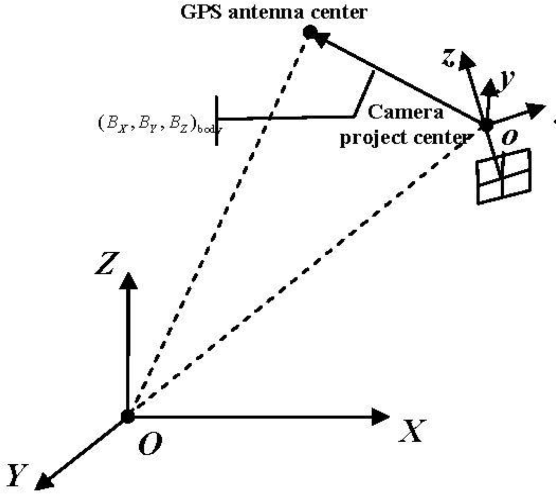
The orbit data observed by GPS receivers is the coordinate of its antenna phase center in WGS84 geocentric euclidean coordinate system. Confined by the size of equipment in the satellite design, there is a position bias between the GPS antenna phase center and the camera's project center, which is called “GPS eccentric vector”, as shown in Figure 2. To determine the coordinate of the camera’s project center in the WGS84 geocentric euclidean coordinate system, an accurate coordinate of the GPS eccentric vector in the satellite’s body-fixed coordinate system denoted as (BX, BY, BZ)body is demanded.
2.1.3. Attitude Measurement Error
Due to the limitation in measurement accuracy, a measurement error often occurs in the attitude data observed by star sensors and gyros, which is called “attitude measurement error”. (Strictly speaking, in addition to the attitude measurement error, an orbit measurement error would appear due to the limitation in measurement accuracy of GPS receiver. However, when considering the optical satellite image, the orbit measurement error has a minor influence on its geometric accuracy compared to that of the attitude measurement error. As the external angle element and line element are strongly correlated, we only take the attitude measurement error into account and treat the orbit measurement error as a part of the attitude measurement error.) In a single scene of image the attitude measurement error can be considered as a constant, whereas there is a degree of random deviation between different scenes of images acquired at different times [2]. Meanwhile, it is noteworthy that, as a scene-dependent random error, it is impossible to distinguish the attitude measurement error from the camera installation angle error using a single scene of an image. In this case, the attitude measurement error in this image is absorbed in the calibrated camera installation angle, which would only affect the geometric accuracy without ground control points, not the geometric accuracy with ground control points. Therefore, strictly speaking, to average down the random error, we should calibrate the camera installation angle using multiple scenes of images whose attitude measurement errors almost meet the normal distribution, as put forward high requirement for the ground reference data. Moreover, even if the camera installation angle is accurately calibrated, for every scene of image, it is still necessary to use ground control points to eliminate its attitude measurement error.
2.1.4. Camera’s Internal Geometric Distortion
There are two groups of distortion errors in an optical camera. One is from the optical distortion of the camera lens, and the other from CCD translation, scale, rotation, and change of the principle distance [24]. As an optical satellite camera uses a linear array CCD for imaging, the distortion error in the direction of orbit caused by the CCD scale and the change of the principle distance are both nearly 0 and can be ignored as well as the distortion error in the direction of CCD caused by CCD rotation. In addition, the lens distortion of optical satellite camera is mainly of low-order distortion because of its narrow field angle. Therefore, an internal geometric distortion model of optical satellite camera can be constructed, as shown in Equation (1), in which the error components in the order of ≤3 are kept, whereas those of >3 are ignored.
Therefore, a rigorous geometric imaging model can be constructed (as described in Equation (2)):
2.2. Geometric Calibration Model
Although the rigorous geometric imaging model takes the major errors into consideration in theory, it cannot be used in practice as an on-orbit geometric calibration model for optical satellite imagery due to over-parameterization. Because of a special imaging condition (i.e., narrow imaging field angle, longer photographic distance and focal length), some system error terms included in the rigorous imaging model are strongly correlated. In addition, some error parameters have less significance for the imagery geometric accuracy. As a result, if we take this model for on-orbit geometric calibration and calculate every system error parameter with ground control points, the calculation equation would be seriously ill-conditioned, and thus the reliability and the accuracy of the calculation results would not be guaranteed. Therefore, to construct an appropriate on-orbit geometric calibration model, taking the rigorous imaging model as beginning, reasonable optimizing and parameter selection is performed as follows:
- (1)
Obviously, the accuracy of laboratory calibration of the GPS eccentric vector as a distance can easily reach centimeter level or higher. Also, during orbiting it changes little, meaning that a geometric positioning error can be neglected, and, therefore, we can use the laboratory calibration result as true value without performing an on-orbit geometric calibration. In contrast, there is always a considerable error in the camera installation angle due to the limitation of the laboratory calibration technology and the change during launching and orbiting, which has a relatively greater influence on the geometric positioning accuracy because of the optical satellite’s high orbit. Related research has proven that the camera installation angle error is the main factor that affects geometric positioning accuracy of the optical satellite imagery and that it must be calibrated periodically. The above analysis of the external errors of an optical satellite camera indicates that we only need to perform on-orbit calibration for the camera installation angle using multiple scenes of image simultaneously and apply the laboratory calibration result directly as true value of the GPS eccentric vector.
- (2)
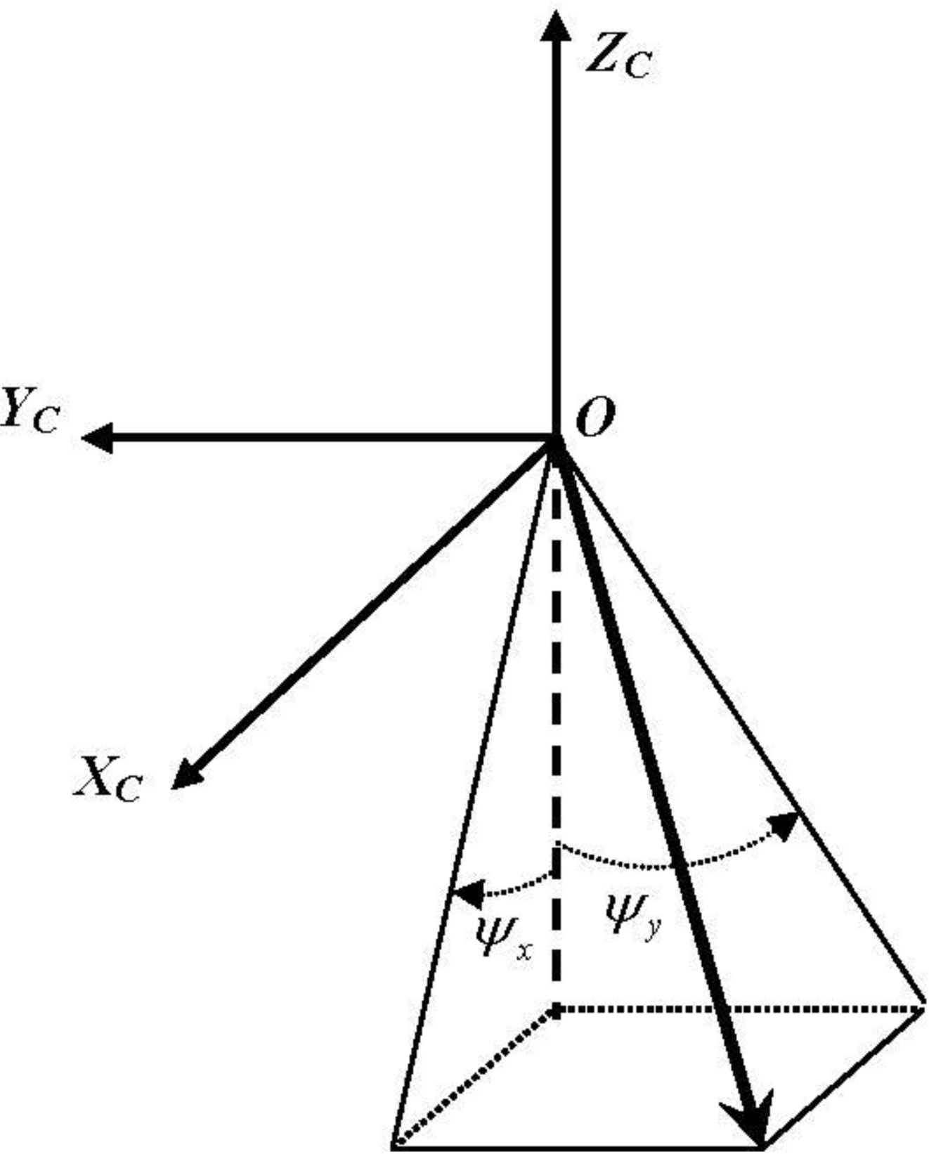
At present, a strict physical model similar to Equation (1) is often adopted as the camera internal distortion model [12–14]. It is noteworthy that every distortion parameter in the strict physical model has a specific physical significance and its calibration relies on the accurate determination of the principal optic axis. However, the external calibration results often inevitably include parts of the camera’s internal errors due to the high correlation between the internal and external systematic errors. For example, the calibration result of the external calibration parameter pitch always contains part of the internal CCD’s translation errors along the track. Considering that with the GPS eccentric vector calibrated in the laboratory, the only angle deviation that exists is between the camera’s coordinate system determined by the external calibration parameters and its true value. At this point in time, all the physical distortion parameters in Equation (1) could not be calibrated precisely without accurate determination of the principle optical axis of camera. Additionally, Equation (1) involves multiple camera distortion parameters of strong correlation, which would inevitably cause the problem of over-parameterization. Therefore, although the camera physical internal distortion model is rigorous in theory, it is not suitable for on-orbit internal calibration. Aiming at this problem in this paper, a detector’s direction angle model is adopted as the internal calibration model instead of Equation (1), which models the direction angle of all detectors under the integrated effect of all physical distortions, not separately taking any specific physical distortion into account. By calibrating the direction angle (ψx, ψy) for each CCD detector in the coordinate system (Figure 3), which is determined by the external calibration results, the direction of each CCD detector in space can be determined accurately with the external calibration parameters and the directional angle of every CCD detector. Therefore the detector direction angle model is adopted in this paper instead of the strict physical model shown in Equation (1). In this paper, a polynomial is adopted to model the directional angles of CCD detectors. It is necessary to make a reasonable determination for the order of the polynomial according to the specific distortion characteristic of different cameras in order to ensure both the precision and stability simultaneously. As the internal geometric distortion of the optical satellite camera is mainly of low-order and less of high-order because of its narrow field of view, in this paper we use an individual three-order polynomial to model the detectors’ directional angles for each CCD for internal calibration (Equation (3)).
where s represents the number of the detector.
ZY-3 three-line array camera has a focal plane design with four CCDs in Forward/Backward and three CCDs in Nadir camera. Strictly speaking, an individual internal calibration model should be built for each CCD. However, by adopting an optical mosaic method with a half transparent and half reflecting mirror, the multiple CCDs can be directly mosaiced into a line with an accuracy of up to 0.3 pixels in Forward, Backward and Nadir cameras, according to the related technical data provided by the satellite designer. After satellite launching, two experiments are conducted for the Forward, Backward, and Nadir camera, respectively. Taking the Nadir camera as an example, in the first experiment each of the three CCDs has its own individual internal calibration model, and in the other experiment, a single internal calibration model is shared by all three CCDs as a whole CCD, and the two experiments are performed using the same ground control points and image. Calculating the differences of the directional angles of all the detectors of the three CCDs determined by two internal calibration results, we found that the differences of all detectors were within 0.2 pixels, which proves that the two experimental results of the three CCDs were very close. Therefore, it is practical to conduct an on-orbit calibration with the three CCDs as a whole CCD, as it is the same for all Forward/Backward and Nadir cameras.
The characteristics of the model are as follows: (1) Using the directional angle of every linear array CCD detector in the camera’s coordinate system as the calibration parameter can skillfully solve the problem that the physical distortion parameters of the camera could not be calibrated precisely because the principle optical axis cannot be accurately determined due to close coupling between the external and internal system errors. Although the internal system errors are partially included in the external calibration results, resulting in inaccurate measurements in the direction of the three axes of the camera’s coordinate system, this does not hamper the calculation of the internal calibration parameters. Via coupling with the internal and external calibration parameters, the systematic geometric error can still be precisely eliminated to restore the precise direction of every CCD detector in space (somewhat of a combination and redistribution of the systematic errors); (2) A cubic polynomial is adopted to describe the directional angle of every CCD detector, the internal calibration parameters are coefficients of a cubic polynomial, and have high orthogonality and low correlation.
According to the analysis above, an on-orbit geometric calibration model is constructed for the optical satellite image, as expressed in Equation (4). An external calibration parameter XE = is used to compensate the camera installation angle and determine the attitude of the camera coordinate system. An internal calibration parameter XI = (a0, a1, a2, a3, b0, b1, b2, b3) is used to determine the directional angles of all CCD detectors in the camera coordinate system.
2.3. Determining the Parameters
In literature [2], calculation of the external and internal calibration parameter was discussed separately, however a detailed calculation procedure is not presented. In this paper, the internal and external calibration parameters are determined by alternating between estimation of external and internal parameters. The steps and equations are specified as follows:
Auto measurement of control points: By matching the satellite image with the orthophoto and the corresponding DEM of high accuracy provided by the ground calibration test site with the image correlation technique, we can automatically measure K evenly distributed and highly accurate ground control points. The coordinate of every control point in the WGS84 geocentric euclidean coordinate system is (Xi, Yi, Zi), and the corresponding image point’s coordinate is (si, li,), i = 1, 2, 3, …, K. It is necessary to require a certain number and distribution of control points to ensure the quality of the calibration result. The SNR in the adjustment model is always low when we use the control points to execute the adjustment calculation of the calibration parameters due to various incidental factors. According to the adjustment theory, to improve the calculation accuracy of the calibration parameters, the number of the observation samples (i.e., the object control points) should be increased. Additionally, as an optical satellite uses a line array CCD to acquire images, each scan line has a set of external orientation parameter. Strictly speaking, due to the limitation in the observation frequency of GPS receiver, star sensor and gyros, and the influence of the satellite jitter, the external orientation parameter error varies among scan lines, meaning that there is a relative error of external orientation parameters between any two scan lines, and the error increases with the increase of imaging time interval. Therefore, to reduce the relative error of the exterior orientation observations and to improve the SNR of the adjustment model as much as possible, it is required that the control points should distribute as closely as possible along orbit orientation and uniformly on the whole CCD.
The following procedure must be followed:
Initialize the internal and external calibration parameters XE and XI with the pre launch calibration and .
Determining the external calibration parameters: Consider the current internal calibration parameter as the “true value” and the external calibration parameter as the unknown parameter. Insert (XE, XI) into Equation (4), linearize Equation (4) at every orientation point and then develop error Equation (5):
Li is the error vector calculated by the current internal and external calibration parameters ( , ), Ai is the parameter matrix of the error equation, X represents the correction of the external calibration parameter (dpitch, droll, dyaw) and Pi is the weight of the observation value.
Calculate X by the least-squares adjustment method:
Next, update the current value of the external calibration parameter XE and conduct the calculation iteratively until the correction values of all the external calibration parameters are within a threshold.
- (1)
Determining the internal calibration parameters: Consider the current value of the external calibration parameter as the “true value” and the internal calibration parameter as an unknown parameter. The process is similar to that of the external calibration parameter in Step 3 and so the specific equation and process are omitted here;
- (2)
Set XE = X′E and XI = X′I and execute Steps (3) and (4) iteratively until the external and internal calibration parameters tend to be convergent and stable;
- (3)
Update the camera’s parameter file according to the calibration result.
Strictly speaking, to average down the attitude measurement error, we should calculate the camera installation angle using multiple scenes of images. In this case, the external calibration parameter for each scene of image is simply calculated individually, and then all external calibration results are averaged to the final combined external calibration result. Moreover, if the internal calibration has been performed earlier, there is less internal geometric distortion of all these images in the camera, and thus for each image only five ground control points, evenly distributed in its four corners and the center, are needed to calculate the external calibration parameters.
3. Experiment Data and Result Analysis
3.1. Experimental Data
To verify the correctness and feasibility of the proposed calibration model and calculation method, an on-orbit geometric calibration experiment for ZY1-02C panchromatic camera and ZY-3 three-line array camera is conducted. As the available reference data is limited, in this paper we perform an on-orbit calibration experiment for ZY1-02C panchromatic camera only by using a scene of image covered by the reference data provided by the Henan Songshan geometric calibration test site, as well as a ZY-3 three-line array camera. Detailed information about the satellite image data and reference data are listed in Tables 1 and 2, respectively. Further on-orbit calibration experiments and analyses on the variation with time for the external calibration parameters using multiple scenes of image will be carried out in a follow-up study when sufficient data is available.
3.2. Experimental Results and Analysis
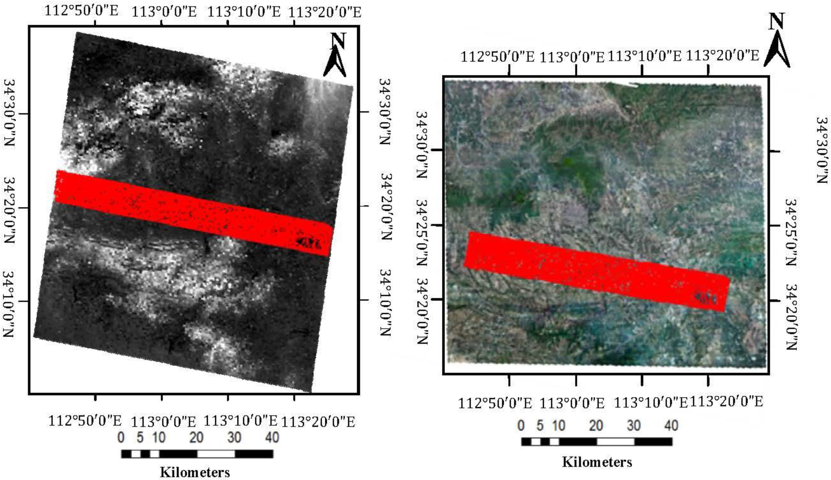
By matching the ZY1-02C’s panchromatic image with the reference data provided by the Henan Songshan geometric calibration test site, a number of corresponding points are automatically acquired that can be used as control points to determine the internal calibration parameters. The corresponding object coordinates can be directly obtained from the reference DOM and DEM. According to the methodology, we should choose control points distributed in a region that is as short as possible along the orbit orientation and uniformly on the whole CCD along the direction vertical to the orbit. The red triangulations are composed of 48,833 pervasive corresponding points that were obtained by auto-matching (Figure 4).
The calibration parameters for the ZY1-02C panchromatic camera were calculated using the control points shown in Figure 4. The values of the external calibration parameters before and after calibration are listed in Table 3.
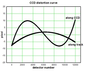
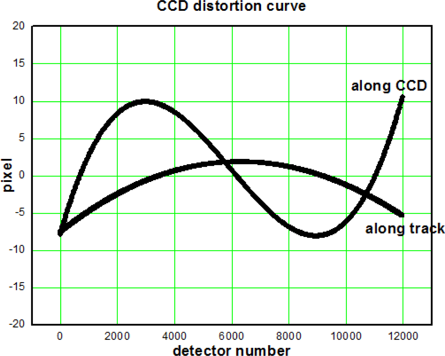
To analyze the characteristics of the camera’s internal distortion objectively and quantitatively, one out of every 50 detectors in the camera’s CCD was sampled, from which differences in directional angles of those samples pre- and post-calibration were calculated and then plotted in a distortion curve (Figure 5).
To evaluate the effectiveness of the calibration results, we choose multiple ZY1-02C panchromatic images in the regions of Zhengzhou in Henan, Huairou in Beijing, and Aramon in France. To verify the geometric accuracy of these images before and after calibration, two sets of RPC are generated respectively based on the design value and calibrated value of the calibration parameters. An translation model and an affine transform model on the image space of the RPC is used respectively for correction with one GCPs and not less than three GCPs. The experimental results are listed in Table 4.
Using the same method as above, on-orbit geometric calibration experiments are also performed for ZY-3 three-line array camera with the reference data of the Songshan calibration test site. The following provides a brief description of the image matching result, the calibration result and the geometric accuracy before and after the calibration under different control conditions in the experiments.
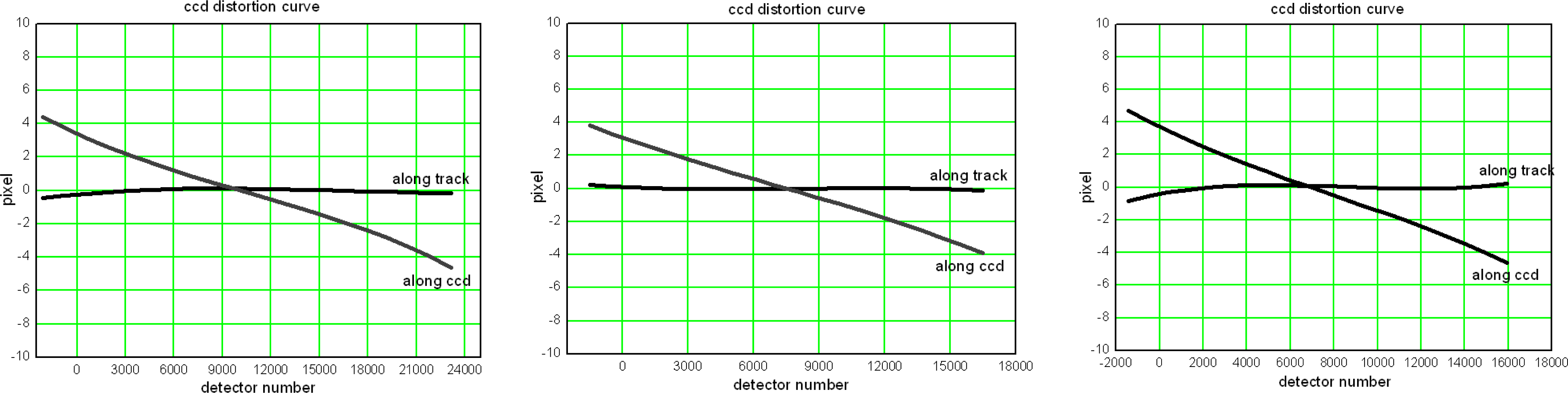
By matching the Nadir, Forward and Backward imagery of ZY-3 three-line array camera with the reference data, 76,893, 61,270, and 63,012 corresponding image points are acquired, respectively. Using these corresponding image points as control points, the calibration parameters of ZY-3 three-line array camera are calculated. Table 5 lists the external calibration results, and Figure 6 demonstrates the internal distortion curve of ZY-3 three-line array camera.
Table 6 lists the stereo geometric accuracy of multiple images, which cover different areas and are acquired at different times before and after calibration.
The following conclusions can be drawn from the results of the experiment:
- (1)
The camera installation angle changed to some extent during satellite on-orbit operation (Tables 3 and 5). For the ZY1-02C panchromatic camera, the correction values are approximately (350, 170, 320) (arc seconds) in the order pitch, roll, and yaw, respectively. Those of ZY-3 Nadir, Forward and Backward camera are (430, 390, 710), (−350, 400, 700), (270, 350, 660), respectively. These errors could significantly degrade the positioning accuracy of satellite imagery without control if on-orbit calibration for the camera installation angle is not done periodically.
- (2)
From the distortion curve shown in Figure 5, we found that an obvious nonlinear distortion exists both along track and in its perpendicular direction in the ZY1-02C panchromatic camera. The maxima of the internal distortion error along track and along CCD reached up to 7 pixels and 10 pixels, respectively. Therefore, internal calibration must be done for the ZY1-02C panchromatic camera; otherwise, internal geometric distortion would be remarkable and the geometric quality of the images would be reduced considerably. In contrast, for the ZY-3 three-line array camera, Figure 6 indicates that there is almost no internal distortion along track, only a linear inner distortion along CCD which is likely generated by the adjustment of the focal length, which provides strong evidence for its non-distortion lens design.
- (3)
In Tables 4 and 6, we see that although only using a scene of image, the external calibration results contain the attitude measurement error. The geometric accuracy without control of the ZY1-02C panchromatic images and the ZY-3 three-line array images have been greatly improved, this suggests that compared to the attitude measurement error, the camera installation angle error is relatively more significant and the main factor influencing the geometric accuracy without control. Moreover, having the internal distortion error of the images removed effectively in calibration, the geometric accuracy is enhanced and stabilized with a smaller number of control points (only one to three) than before calibration. This practice not only improves the geometric quality of the image products greatly but also significantly reduces the control cost in the follow-up processes and applications.
4. Conclusions
In this paper, we proposed an on-orbit geometric calibration model and corresponding calculation method for optical satellite imagery. Experiments were performed for ZY1-02C panchromatic camera and ZY-3 three-line array camera using the proposed model and method with high-precision reference data supported by the Songshan calibration test site that was built by Wuhan University. The experimental results show that although the ZY1-02C panchromatic camera and the ZY-3 three-line array camera were calibrated in the laboratory before launch, the laboratory calibration parameters would experience a certain amount of deviation during satellite on-orbit operation. This is likely caused by many factors, including installation, launching, and orbiting. Therefore, on-orbit geometric calibration is necessary. Otherwise, the geometric quality of images will not be able to meet requirements of subsequent processes and applications. Meanwhile, we chose multiple images that covered different areas and were obtained at various times to verify their geometric accuracy before and after calibration. The result indicates that with the proposed on-orbit calibration model and calculation method, the geometric accuracy of the imagery is significantly improved and stabilized with or without ground control points. Additionally, as the internal distortion error of the images is eliminated effectively, requirements for the number of the ground control points are greatly reduced while the geometric accuracy with ground control is higher after calibration.
Noticing that as the available reference data is limited, in this paper we perform a calibration experiment by only using a scene of image. Therefore analysis on the variation with time in the external calibration parameters during on-orbit operation remains insufficient. More in-depth studies and comprehensive experiments using different terrain and globally distributed reference areas will be carried out in the future.
Acknowledgments
This work was supported in part by the National Basic Research Program of China 973 Program under grant 2012CB719902, 2014CB744201; the Program for New Century Excellent Talents in University; the National High Technology Research and Development Program of China (No. 2011AA120203); the Fundamental Research Funds for the Central Universities (No. 2012619020205); the Foundation for the Author of National Excellent Doctoral Dissertation of PR China (FANEDD, No. 201249); the National Natural Science Foundation of China (No. 41371430); and the Program for Changjiang Scholars and Innovative Research Team in University under grant IRT1278.
Author Contributions
The first author conceived the study and designed the experiments; The second author developed the algorithm and wrote the program; The third author performed the experiments; The fourth author helped perform the analysis with constructive discussions and contributed to manuscript preparation.
Conflicts of Interest
The authors declare no conflict of interest.
References
- Radhadevi, P.V.; Solanki, S.S.; Jyothi, M.V.; Nagasubramanian, V.; Geeta, V. Automated co-registration of images from multiple bands of Liss-4 camera. ISPRS J. Photogramm. Remote Sens 2009, 64, 17–26. [Google Scholar]
- Robertson, B.; Beckett, K.; Rampersad, C.; Putih, R. Quantative Geometric Calibration and Validation of the Rapideye Constellation. Proceedings of the 2009 IEEE International Geoscience and Remote Sensing Symposium, Cape Town, South Africa, 12–17 July 2009.
- Greslou, D.; Delussy, F.; Delvit, J.; Dechoz, C.; Amberg, V. PLEIADES-HR Innovative Techniques for Geometric Image Quality Commissioning. Proceedings of the 2012 XXII ISPRS Congress International Archives of the Photogrammetry, Remote Sensing and Spatial Information Sciences, Melbourne, VIC, Australia, 25 August–1 September 2012.
- Delussy, F.; Greslou, D.; Dechoz, C.; Amberg, V.; Delvit, J.; Lebegue, L.; Blanchet, G.; Fourest, S. PLEIADES HR In-Flight Geometric Calibration: Location and Mapping of the Focal Plane. Proceedings of the 2012 XXII ISPRS Congress International Archives of the Photogrammetry, Remote Sensing and Spatial Information Sciences, Melbourne, VIC, Australia, 25 August–1 September 2012.
- Mulawa, D. On-orbit geometric calibration of the Orbview-3 high resolution imaging satellite. Int. Arch. Photogramm. Remote Sens. Spat. Inf. Sci 2004, 35, 1–6. [Google Scholar]
- Bouillon, A.; Bernard, M.; Gigord, P.; Orsoni, A.; Rudowski, V.; Baudoin, A. SPOT 5 HRS geometric performances: Using block adjustment as a key issue to improve quality of DEM generation. ISPRS J. Photogramm. Remote Sens 2006, 60, 134–146. [Google Scholar]
- Kornus, W.; Alamus, R.; Ruiz, A.; Talaya, J. DEM generation from SPOT-5 3-fold along track stereoscopic imagery using autocalibration. ISPRS J. Photogramm. Remote Sens 2006, 60, 147–159. [Google Scholar]
- Fraser, C.S.; Baltsavias, E.P.; Gruen, A. Processing of IKONOS imagery for submetre 3D positioning and building extraction. ISPRS J. Photogramm. Remote Sens 2002, 56, 177–194. [Google Scholar]
- Baltsavias, E.; Zhang, L.; Eisenbeiss, H. DSM generation and interior orientation determination of IKONOS images using a Testfield in Switzerland. Photogramm. Fernerkund. Geoinf 2006, 1, 41–54. [Google Scholar]
- Gruen, A.; Kocaman, S.; Wolff, K. Calibration and validation of early ALOS/PRISM images. J. Jpn. S. Photogramm. Remote Sens 2007, 46, 24–38. [Google Scholar]
- Takeo, T.; Masanobu, S.; Hiroshi, M.; Junichi, T. Calibration of PRISM and AVNIR-2 onboard ALOS “Daichi”. IEEE Trans. Geosci. Remote Sens 2009, 47, 4042–4050. [Google Scholar]
- Kocaman, S.; Gruen, A. Orientation and self-calibration of ALOS PRISM imagery. Photogramm. Rec 2008, 23, 323–340. [Google Scholar]
- Junichi, T.; Takeo, T. PRISM on-orbit geometric calibration and DSM performance. IEEE Trans. Geosci. Remote Sens 2009, 47, 4060–4073. [Google Scholar]
- Radhadevi, P.V.; Mueller, R.; d’Angelo, P.; Reinartz, P. In-flight geometric calibration and orientation of ALOS/PRISM imagery with a generic sensor model. Photogramm. Eng. Remote Sens 2011, 77, 531–538. [Google Scholar]
- Moorthi, S.M.; Kayal, R.; Krishnan, R.R.; Srivastava, P.K. Resourcesat-1 LISS-4 MX bands onground co-registration by in-flight calibration and attitude refinement. Photogramm. Rec 2008, 10, 140–146. [Google Scholar]
- Fang, L.Y.; Wang, M.; Li, D.R.; Pan, J. CPU/GPU near real-time preprocessing for ZY-3 satellite images: Relative radiometric correction, MTF compensation, and geocorrection. ISPRS J. Photogramm. Remote Sens 2014, 87, 229–240. [Google Scholar]
- Tang, X.M.; Xie, J.F. Overview of the key technologies for high-resolution satellite mapping. Int. J. Digit. Earth 2012, 5, 228–240. [Google Scholar]
- Wang, M.; Yang, B.; Jin, S.Y. A registration method based on object-space positioning consistency for satellite multi-spectral image. Geomat. Inf. Sci. Wuhan Univ 2013, 38, 765–769. [Google Scholar]
- Yang, B.; Wang, M. On-orbit geometric calibration method of ZY102C panchromatic camera. J. Remote Sens 2013, 17, 1175–1190. [Google Scholar]
- Tang, X.M.; Zhang, G.; Zhu, X.Y.; Pan, H.B.; Jiang, Y.H.; Zhou, P.; Wang, X. Triple linear-array imaging geometry model of ZiYuan-3 surveying satellite and its validation. Int. J. Image Data Fusion 2013, 41. [Google Scholar] [CrossRef]
- Chen, Q.; Wang, S.G.; Wang, B.; Sun, M.W. Automatic registration method for fusion of ZY-102C Satellite images. Remote Sens 2014, 6, 157–179. [Google Scholar]
- Radhadevi, P.V.; Solanki, S.S. In-flight geometric calibration of different cameras of IRS-P6 using a physical sensor model. Photogramm. Rec 2008, 23, 69–89. [Google Scholar]
- Zhang, C.S.; Fraser, C.S.; Liu, S.J. Interior Orientation Error Modelling and Correctrion for Precise Georeferencing of Satellite Imagery. Proceedings of the 2012 XXII ISPRS Congress International Archives of the Photogrammetry, Remote Sensing and Spatial Information Sciences, Melbourne, VIC, Australia, 25 August–1 September 2012.
- Chen, T.E.; Shibasaki, R.; Lin, Z.J. A rigorous laboratory calibration method for interior orientation of an airborne linear push-broom camera. Photogramm. Eng. Remote Sens 2007, 73, 369–374. [Google Scholar]


| ZY1-02C Panchromatic Camera | ZY-3 Three-Line Array Camera | |
|---|---|---|
| GSD (m) | 5 | Nadir: 2.1 Forward/Backward: 3.5 |
| Image Size (pixels) | 12,000 × 12,000 | Nadir: 24,530 × 24,575 Forward/Backward: 16,300 × 16,383 |
| Focal Length (mm) | 1010 | 1700 |
| Acquisition time | 23 January 2012 | 3 February 2012 |
| Area Covered | Range: 60 km × 60 km Location: Henan Songshan Terrain type: Mountainous and hilly | |
| DOM | DEM | |
|---|---|---|
| GSD (m) | 0.2 | 1 |
| Geometric Precision (RMSE/m) | Planimetric accuracy: 1 | Height accuracy: 2 |
| Area Covered | Range: 100 km × 100 km Location: Henan Songshan Terrain type: Mountainous and hilly | |
| External Calibration Parameters (deg) | Before Calibration | After Calibration | Correction Value |
|---|---|---|---|
| pitch | 0.0 | 0.097078 | 0.097078 |
| roll | 0.0 | −0.046805 | −0.046805 |
| yaw | 0.0 | −0.090407 | −0.090407 |
| Positioning Accuracy before and after Calibration of the ZY1-02C Panchromatic Camera | ||||||
|---|---|---|---|---|---|---|
| Test Site (Acquisition Time) | Control Point Number | Check Point Number | Root Mean Square Error of the Residual Error of Check Point before Calibration in Image Space (Pixel) | Root Mean Square Error of the Residual Error of Check Point after Calibration in Image Space (Pixel) | ||
| Along-Track | Vertical Track | Along-Track | Vertical Track | |||
| ZhenZhou, HeNan (2012.4.18) | 0 | 22 | 282.2 | 103.0 | 18.6 | 7.7 |
| 1 | 21 | 6.6 | 8.1 | 1.6 | 0.96 | |
| 3 | 19 | 6.3 | 7.7 | 1.2 | 0.85 | |
| 4 | 18 | 5.8 | 7.4 | 1.1 | 0.7 | |
| 8 | 14 | 5.6 | 6.8 | 0.95 | 0.7 | |
| HuaiRou, Beijing (2012.2.1) | 0 | 21 | 267.2 | 95.8 | 6.4 | 11.7 |
| 1 | 20 | 6.4 | 6.9 | 2.0 | 1.3 | |
| 3 | 18 | 6.1 | 6.6 | 1.4 | 1.1 | |
| 5 | 16 | 6.0 | 6.5 | 1.3 | 1.0 | |
| 7 | 14 | 5.9 | 6.5 | 1.3 | 0.9 | |
| Aramon, France (2012.6.14) | 0 | 24 | 268.7 | 92.3 | 5.0 | 14.2 |
| 1 | 23 | 7.8 | 7.4 | 2.0 | 1.4 | |
| 3 | 21 | 7.4 | 7.1 | 1.8 | 1.2 | |
| 5 | 19 | 6.9 | 6.9 | 1.7 | 1.1 | |
| 7 | 17 | 6.1 | 6.5 | 1.3 | 1.1 | |
| External Calibration Parameters (deg) | NAD | FWD | BWD | ||||||
|---|---|---|---|---|---|---|---|---|---|
| Before Calibration | After Calibration | Correction Value | Before Calibration | After Calibration | Correction Value | Before Calibration | After Calibration | Correction Value | |
| pitch | 0.0 | 0.076662 | 0.076662 | 22.0 | 21.879654 | −0.120346 | −22.0 | −22.097722 | −0.097722 |
| roll | 0.0 | −0.098950 | −0.098950 | 0.0 | −0.109721 | −0.109721 | 0.0 | −0.111211 | −0.111211 |
| yaw | 0.0 | −0.184034 | −0.184034 | 0.0 | −0.198358 | −0.198358 | 0.0 | −0.194175 | −0.194175 |
| Stereo Positioning Accuracy before and after Calibration of ZY-3 Three-Line Array Camera. | ||||||
|---|---|---|---|---|---|---|
| Test Site (Acquisition Time) | Control Point Number | Check Point Number | Root Mean Square Error of the Residual Error of Check Point before Calibration in Object Space (m) | Root Mean Square Error of the Residual Error of Check Point after Calibration in Object Space (m) | ||
| Plane | Height | Plane | Height | |||
| NanYang, Henan (3 July 2012) | 0 | 19 | 1495.5 | 272.9 | 3.3 | 10.2 |
| 1 | 18 | 61.8 | 33.2 | 3.2 | 2.9 | |
| 3 | 16 | 65.5 | 33.7 | 2.9 | 2.8 | |
| 5 | 14 | 7.2 | 4.2 | 2.6 | 2.6 | |
| 8 | 11 | 3.0 | 2.9 | 2.3 | 2.6 | |
| LuoYang, Henan (24 January 2012) | 0 | 24 | 1492.1 | 265.8 | 13.9 | 6.1 |
| 1 | 23 | 38.8 | 19.6 | 4.2 | 3.6 | |
| 3 | 21 | 40.9 | 20.1 | 3.3 | 3.1 | |
| 5 | 19 | 5.8 | 3.2 | 3.2 | 2.8 | |
| 8 | 16 | 3.1 | 2.7 | 2.6 | 2.5 | |
| TaiYuan, Shanxi (13 May 2012) | 0 | 21 | 1486.4 | 305.9 | 12.6 | 7.2 |
| 1 | 20 | 38.2 | 20.5 | 4.4 | 4.1 | |
| 3 | 18 | 49.7 | 26.6 | 3.1 | 2.9 | |
| 5 | 16 | 6.4 | 5.4 | 2.9 | 2.9 | |
| 8 | 13 | 3.2 | 3.1 | 2.7 | 2.6 | |
© 2014 by the authors; licensee MDPI, Basel, Switzerland This article is an open access article distributed under the terms and conditions of the Creative Commons Attribution license (http://creativecommons.org/licenses/by/3.0/).
Share and Cite
Wang, M.; Yang, B.; Hu, F.; Zang, X. On-Orbit Geometric Calibration Model and Its Applications for High-Resolution Optical Satellite Imagery. Remote Sens. 2014, 6, 4391-4408. https://doi.org/10.3390/rs6054391
Wang M, Yang B, Hu F, Zang X. On-Orbit Geometric Calibration Model and Its Applications for High-Resolution Optical Satellite Imagery. Remote Sensing. 2014; 6(5):4391-4408. https://doi.org/10.3390/rs6054391
Chicago/Turabian StyleWang, Mi, Bo Yang, Fen Hu, and Xi Zang. 2014. "On-Orbit Geometric Calibration Model and Its Applications for High-Resolution Optical Satellite Imagery" Remote Sensing 6, no. 5: 4391-4408. https://doi.org/10.3390/rs6054391