5.1. Data Presentation
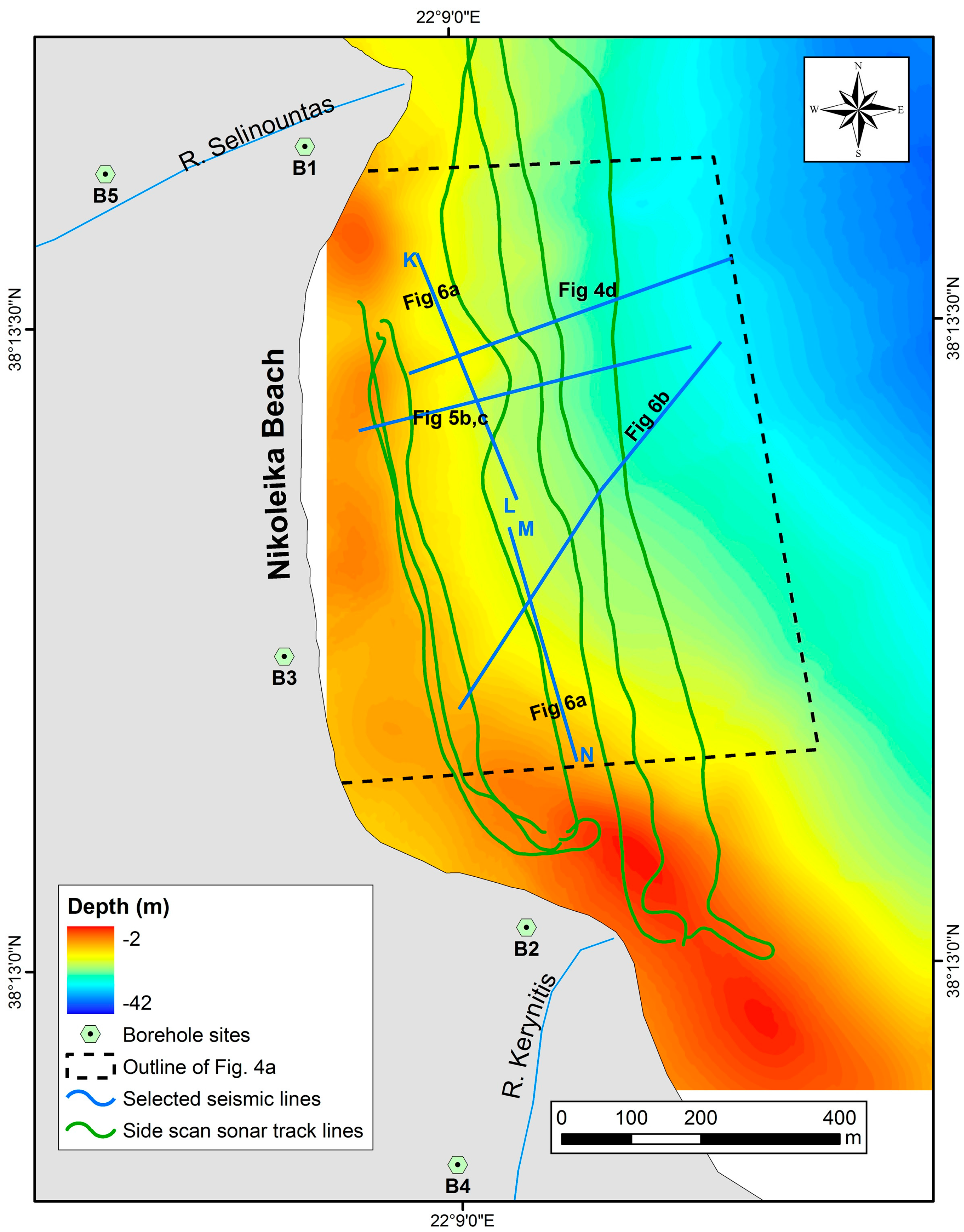
A detailed marine remote sensing survey in the near shore zone between the Selinountas and Kerynitis rivers (Nikoleika beach), on which Helike was situated, have shown that after the 6.2 R earthquake in 1995 the coastal and near-shore zone was affected by a landslide. The study of the side scan sonar data revealed five distinct acoustic backscatter patterns (
Figure 4a and
Figure 5a). The interpretation of those backscatter patterns together with the seismic profiling data have shown that each pattern may be attributed to a distinctive part or feature of the landslide: (i) a strong backscatter zone running parallel to the coastline represents the head scarp (Hs) of the landslide; (ii) an area of moderate reflectivity is attributed to the evacuation zone (Ez) of the landslide; (iii) narrow linear areas of high reflectivity accompanied with narrow zones of acoustic shadow (dark tone) ascribe to the compressional zone (Cz) of the landslide; (iv) an extended uniform low-reflectivity area represents the undisturbed fine-grained sediments (Us) of the seafloor; and (v) localized strong backscatter facies in low reflectivity seafloor is attributed to the distal deposits (out-runners) (Or) of the landslide (
Figure 4 and
Figure 5).
The landslide had in plan-view an almost amphitheatrical shape extending parallel to the coastline, as is indicated by the spatial distribution of the backscatter patterns (
Figure 4 and
Figure 5). The landslide had a width of 1200 m along the shoreline and a length of 600 m across it.
Figure 4.
(
a) Side scan sonar mosaic showing different backscatter acoustic patterns; (Hs): Head scarp, (Ez): Evacuation zone, (Cz): compressional zone, (Or): out-runners, (Us): Undisturbed sediments; (
b,
c) Photographs showing the slide crown and the associated
en echelon fault rotated blocks (crown cracks-Cc), which affected the beach, and trees standing in the surf zone indicative for the submerged part of the beach, respectively, and (
d) seismic profile across the coastal landslide showing (Ez): Evacuation zone, (Cz): compressional zone, (Sp): Slip plane. For the location of the mosaic and the profile see
Figure 3.
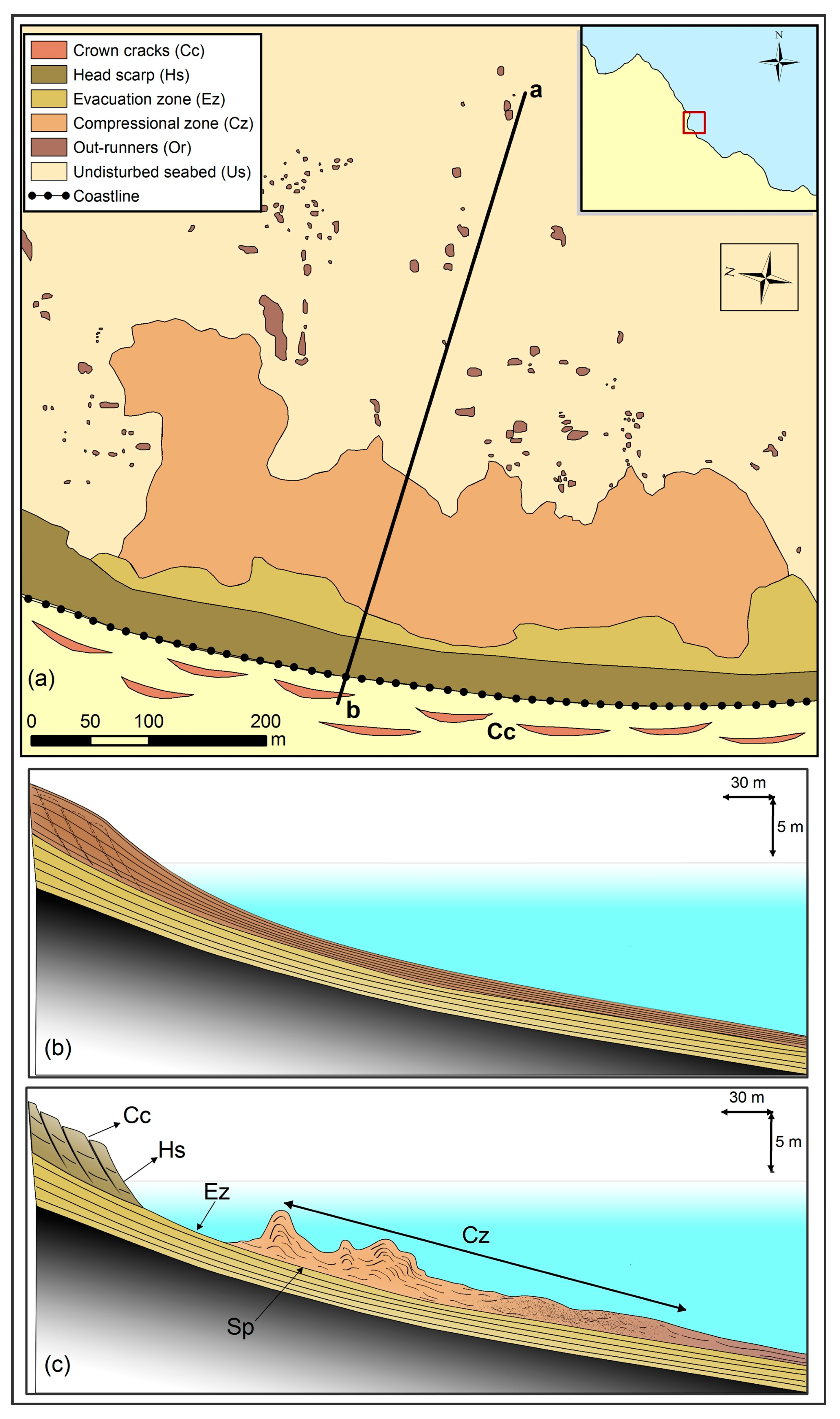
Figure 5.
(
a) Simplified schematic map of the coastal landslide showing the above mentioned features as interpreted from the sonar mosaic and seismic profiles; Sketch drawing showing a seabed profile before (
b) and after (
c) the 1995 earthquake. (Cc): Crown cracks, (Hs): Head scarp, (Ez): Evacuation zone, (Cz): compressional zone, (Sp): Slip plane. For the location of the profile ab see
Figure 3.
The seismic reflection profiles in the dip direction show that the sliding took place over a single basal glide plane, about 3–5 m below the seafloor, which is also a bedding plane, dipping at about 0.5°–1° (
Figure 4d). The seismic profiles together with backscatter acoustic patterns show that the slide can be divided into: (i) the head scarp zone; (ii) the evacuation zone; (iii) the compressional zone; and (iv) the distal deposits (
Figure 5a).
The head scarp zone onshore is affected by shallow rotational slides as is indicated by the formation of rotated and landward tilted blocks, which are separated by scarps with a height of 0.5 to 1 m (
Figure 4 and
Figure 5). The scarps were parallel to the shoreline and the blocks have dimensions of 10–15 m and 30–70 m perpendicular and parallel to the shoreline, respectively (
Figure 5). Landward of the head scarp zone, ground cracks about 10 m long and 0.1 m wide were observed (
Figure 4b,c). Sand and water erupted from most of the cracks indicating that sediment liquefaction occurred in the deeper layers during the earthquake.
The slide plane/evacuation zone is related to one of the sub-bottom reflections and corresponds to a bedding plane within the stratified sedimentary sequence with an overall seaward dipping gradient of 0.5°–1° (
Figure 4a,d and
Figure 5).
The compressional zone in the upper part is characterized by high relief undulations with an elevation between 2 and 4 m corresponding to pressure ridges (
Figure 4a,d), which developed perpendicular to the slide direction (
Figure 4a). The internal acoustic character of the undulations indicates that the slid sediments have undergone a brittle deformation (
Figure 4d). The lower part of the compressional zone is characterized by a low hummocky seafloor (
Figure 4d). The internal acoustic character of the sediments underneath indicates that they have undergone plastic deformation during the transportation (
Figure 4d).
The distal deposits are found mainly at the downslope end of the compressional zone, over undisturbed sediments (
Figure 5a). They are individual sediment mounds less than 1 m high and about 5 m long. These are interpreted as glide blocks detached from leading margin of the slide.
Profiles in the strike direction show that the slid mass has a thickness less than 5 m and that within the slid body there are segments that have undergone different styles of deformation during transport, suggesting segmentation of the failed mass into linked discontinuous minor slides (
Figure 6a). The above suggest that the landslide is a complex low-angle translation slide less than 5 m deep.
The seismic profiles show the presence of gas in the interstices of the sediments all over the Helike delta front, at depths more than 10 m below the seafloor, as is indicated by the acoustic turbid zone and gas plumes (
Figure 6b). During the 1995 earthquake, due to the increase of the pore pressure in the sediments caused by the cyclic loading induced by the earthquake, gas and water emanated from the sediments and formed sand volcanoes in the seafloor (
Figure 6b) [
24].
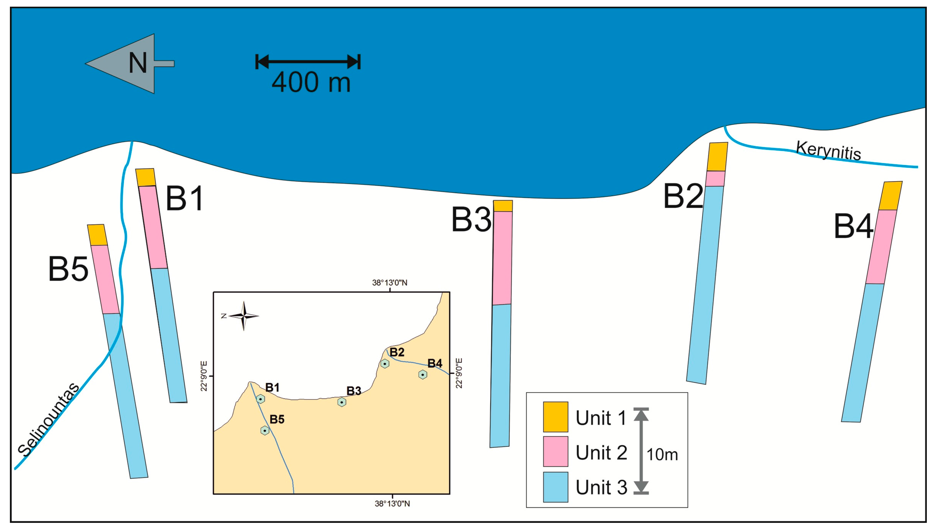
The geotechnical study of the borehole data shows that the delta plain surficial cover is occupied by soft, mainly cohesionless and poorly sorted, deltaic deposits. In detail the subsurface sediments are separated into three general stratigraphic-geotechnical units (
Figure 7).
Unit I consists of non cohesive silty sandy gravel with silty sand inter-layers characterized by medium to high relative density (Dr = 5%–80%) and N
SPT between 15 and 45. The thickness of the unit ranges between 3 and 9.5 m (
Figure 7).
Unit II consists of silty sands with a low percentage of gravelly and clayey sand. They are characterized by low to medium relative density (20%–50%) and penetration resistance (N
SPT) less than 20. The thickness of the unit ranges from 3 to 20 m (
Figure 7).
Figure 6.
(
a) Seismic profiles in the strike direction showing the slide plane all over the area and slid masses with different styles of deformation during transport; (Cz): compressional zone, (Pd): slide deposits that have undergone plastic deformation, (Us): undisturbed sediments, (Sp): Slip plane, (ATZ): Acoustic turbid zone; (
b) Seismic profile in the dip direction showing the presence of gas below the surficial sediments as indicated by the acoustic turbid zone (ATZ) and gas plumes (GPL). The disruption of the stratified surficial reflections by piercement like feature indicate the presence of sand volcano (Sv) formed by the expulsion of water and gas induced by the earthquake. (Or): Out-runners. For the seismic profiles location see
Figure 3.
Figure 7.
Three-dimensional representation of the three stratigraphic-geotechnical units recovered from the boreholes.
Figure 7.
Three-dimensional representation of the three stratigraphic-geotechnical units recovered from the boreholes.
Unit III is in depths more than 14 m, it consists of medium plasticity sandy clays with silt inter layers. The low penetration resistance (N
SPT < 20) together with the relative high values of the unconfined compression strength (20–150 kPa) suggest medium stiff to stiff clay deposits (
Figure 7).
The stability analysis (for more details see [
15]) under undrained conditions revealed that the coastal/near-shore slope appears to be stable (Safety Factor (SF) = 1.50) under condition of static gravitational load and marginally stable to stable (Safety Factor (SF) = 0.90–1.20) under the cyclic loading generated by 6.2 R earthquake in 1995.
The liquefaction potential analysis showed: (i) the presence of liquefaction prone horizons at depths between 4.5 and 15 m having an estimated liquefaction potential (LP) between 0.2 and 0.8; and (ii) that for each test site the required seismic acceleration of between 0.20 and 0.50 g for the non-cohesive sediments of Unit II at depths between 4.5 and 15 m to be liquefied, was exceeded by the peak horizontal ground acceleration of between 0.30 and 0.55 g induced by the 1995 earthquake.
Based on the data presented above, it is postulated that the initiation mechanism responsible for the initiation of the landslide, is liquefaction of a shallow subsurface horizon. This mechanism is further supported by: (i) the extensive presence of sand and water eruption features during the 1861 [
3,
29] and 1995 earthquakes and (ii) the presence of gas in the sediments [
24,
30], which enhances the liquefaction processes.
5.2. Discussion
Geological processes similar to those described in the present study occurred over the same area after an earthquake of an estimated 6.6 R magnitude in December 1861 [
1]. According to Julius Schmidt [
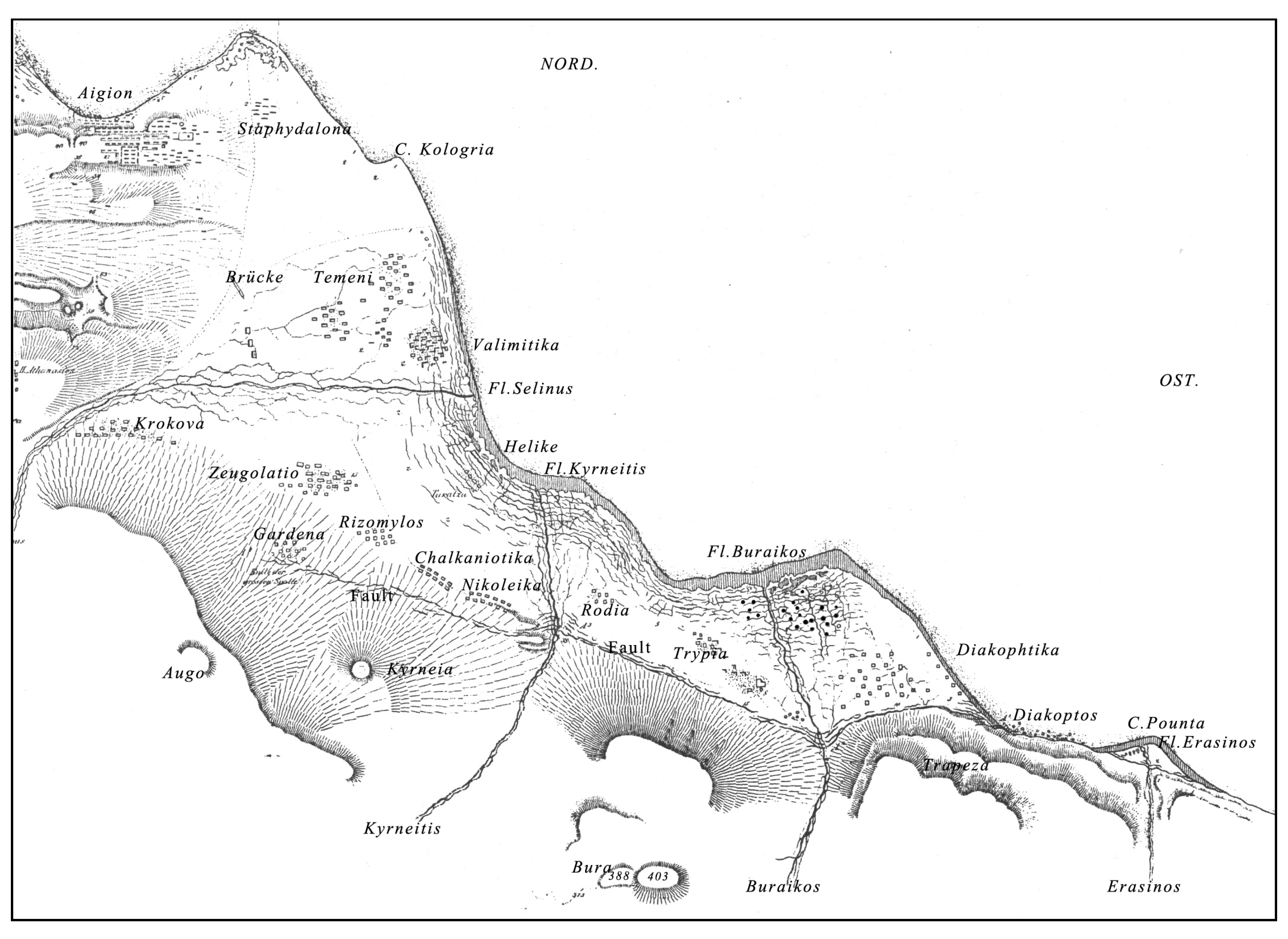
3], who was the director of the Astronomical Institute in Greece, the earthquake opened a 13 km long and 2 m high crack along the base of the foothills, at what is now called the Helike fault. He also mentioned that at the same time numerous fissures, parallel to the shoreline, opened at the surface and sand erupted through them, forming “sand volcanoes” indicative of sediment liquefaction and that a small tsunami with a wave height of 2 m occurred. Furthermore, [
3] reported that the entire delta plain north of the crack slowly subsided, submerging a coastal fringe 13 km long and 200 m wide (
Figure 8 [
31]). He also suggested that Helike was submerged due to a similar but a more violent event [
3].
The above presented information regarding the generation mechanism of the coastal slide induced by the 1995 earthquake along with: (i) geological processes, which occurred over the same area after a 6.6 R magnitude earthquake in December 1861 (Schmidt 3, 31); (ii) the recent geoarchaeological findings about classical Helike [
6,
7]; and (iii) the sequence of events, which led to Helike’s destruction as taken from historical sources, allow us to postulate the following geological process that caused the catastrophe of Helike:
- (1)
Helike was devastated by an earthquake of between 6 to 6.7 R in magnitude. An earthquake of such a magnitude could have devastated any city at that time.
- (2)
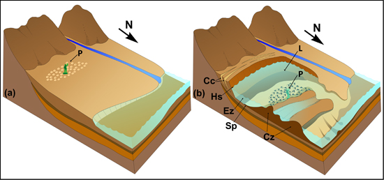
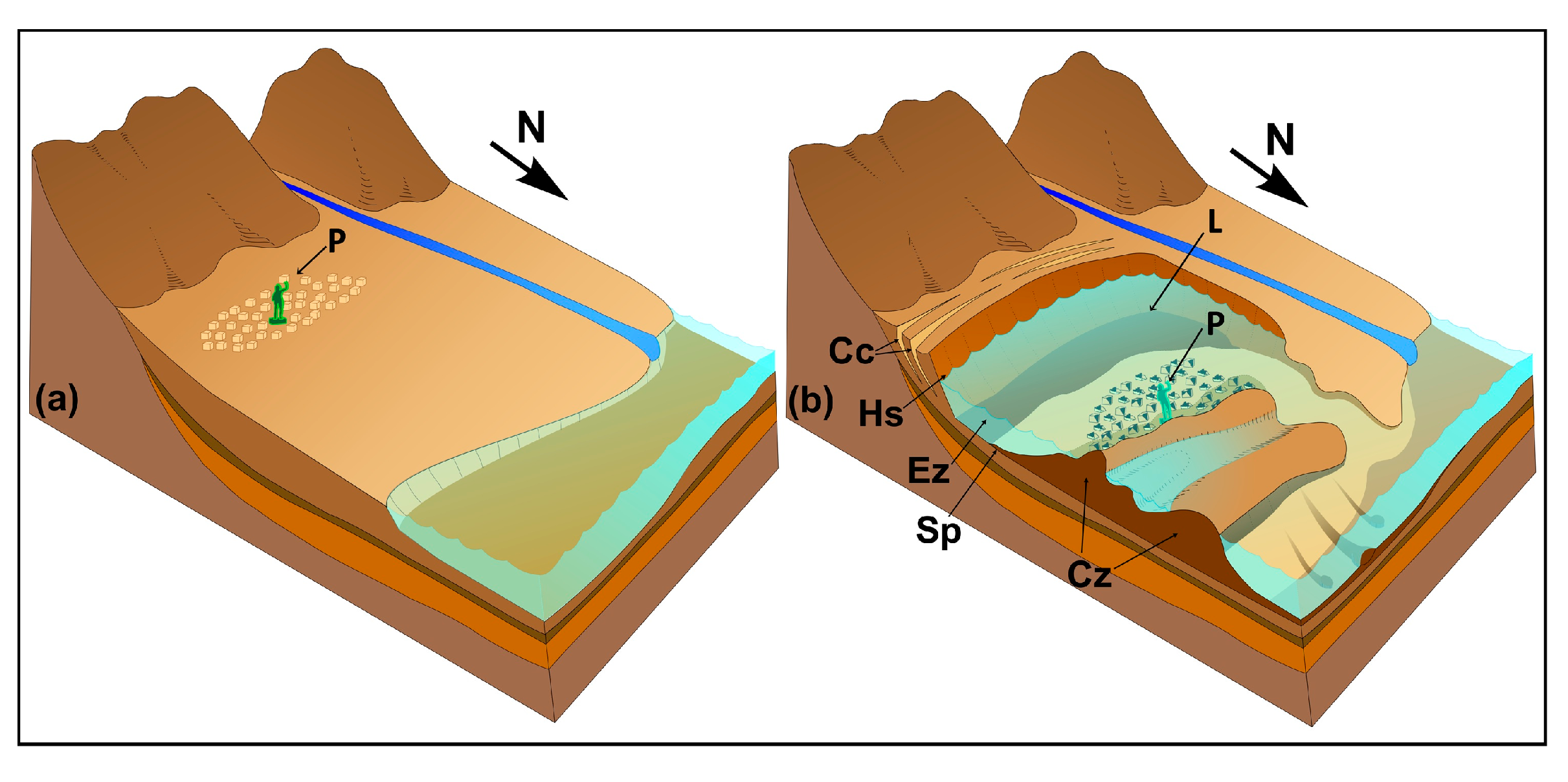
Helike was most probably submerged by a slide of the same type as that which occurred during the 1995 earthquake (
Figure 9). The slide would have had a width of about 1.5 to 2 km, a length of between 1 and 2 km with the slide-crown parallel to the foothills and a thickness between 3 and 5 m. (
Figure 9). Such a slide would have resulted in the seawards transfer of the failed mass on which Helike stood and would have caused enough subsidence of the surface, up to 10 m, in relation to the surrounding land, thus permitting the invasion of the sea over the sliding mass and the submergence of Helike for a long period of time.
Figure 8.
Reproduction of the original map of Schmidt’s map of the Helike Delta, drawn a month after the earthquake of December 1861 [
31]. A fault crack extends along the base of the hills from Pounta to Gardena (modern Keryneia). The shaded fringe by the shore represents the area submerged by the earthquake. Extensive fissuring occurred all along the shore, and sand volcanoes (solid circles) were concentrated on the delta of the Vouraikos River.
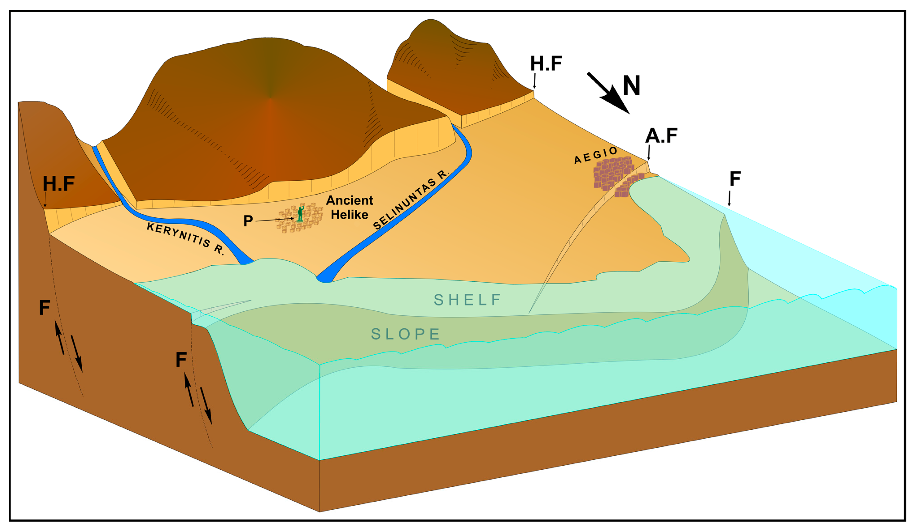
Figure 9.
Three-dimensional sketch map, not in scale, of the landscape reconstruction of the delta plain where Helike was built before (a) and after (b) the translational slide, which affected the surficial sediments and caused the destruction and submergence of Helike. The translational slide in (b) has been enlarged more than that of the delta plain so that its geomorphological features are highlighted. (Cc): Crown cracks, (Hs): head of the slide, (Ez): evacuation zone, (Cz): compressional zone, (Sp): Slip plane and liquefaction horizon, (P): statue of Poseidon in upright position and (L): lagoon.
This model for the devastation/disappearance of Helike agrees with that of: (a) Leonards
et al. [
5], who proposed that the catastrophe of Helike was caused either by soil liquefaction or landsliding, triggered by an earthquake; (b) Schmidt’s [
3,
31] description of events that occurred during the 1861 earthquake; (c) the geoarchaeological findings of Soter and Katsonopoulou [
7]; and (d) the description of events that caused the disappearance of Helike as given by Aelian and Strabo.
Soter and Katsonopoulou (2011) [
7] depicted in their boreholes a clastic layer (their horizon C), which, based on its areal extent and its depth below surface, could have acted as a slip-plane for the postulated translational slide. A translational slide using as a sliding plane Soter’s and Katsonopoulou’s horizon C would have affected the foundation layer on which the Early Bronge Age (E.B.A) settlement lies. However, taking into consideration that: (i) within the 1995 translational slide were segments that were transferred as rigid bodies and (ii) the same could have happened during the 372/373 B.C. earthquake, then it can be concluded that the E.B.A settlement was transferred within the rigid segment without being disturbed. The seaward transport of the slide as a rigid body is supported by Strabo, who wrote that “there was a bronze statue of Poseidon in the straits standing in an up-right position”.
Similarly, in the event that the postulated translational slide had occurred over a slip-plane between 3 and 4 m below surface, would not have affected the layer on which the E.B.A settlement was founded, thus leaving the structures of the settlement undisturbed.
An earthquake triggering a large tsunami, as suggested by Marinatos [
4], cannot account for the disappearance of Helike. A tsunami would have flooded Helike temporarily and would have then retreated. Therefore, Helike would not have remained under water for 500 years. Furthermore, a tsunami would have covered the traces of Helike found with coarse marine sediments instead of fine lagoonal sediments. The tsunami wave height would have been of a much greater height than the maximum expected (>5 m) in order to invade the coastal zone 1 km inland and thus to flood Helike. Such a tsunami would have affected within 10 min a much wider area around the Corinth Gulf [
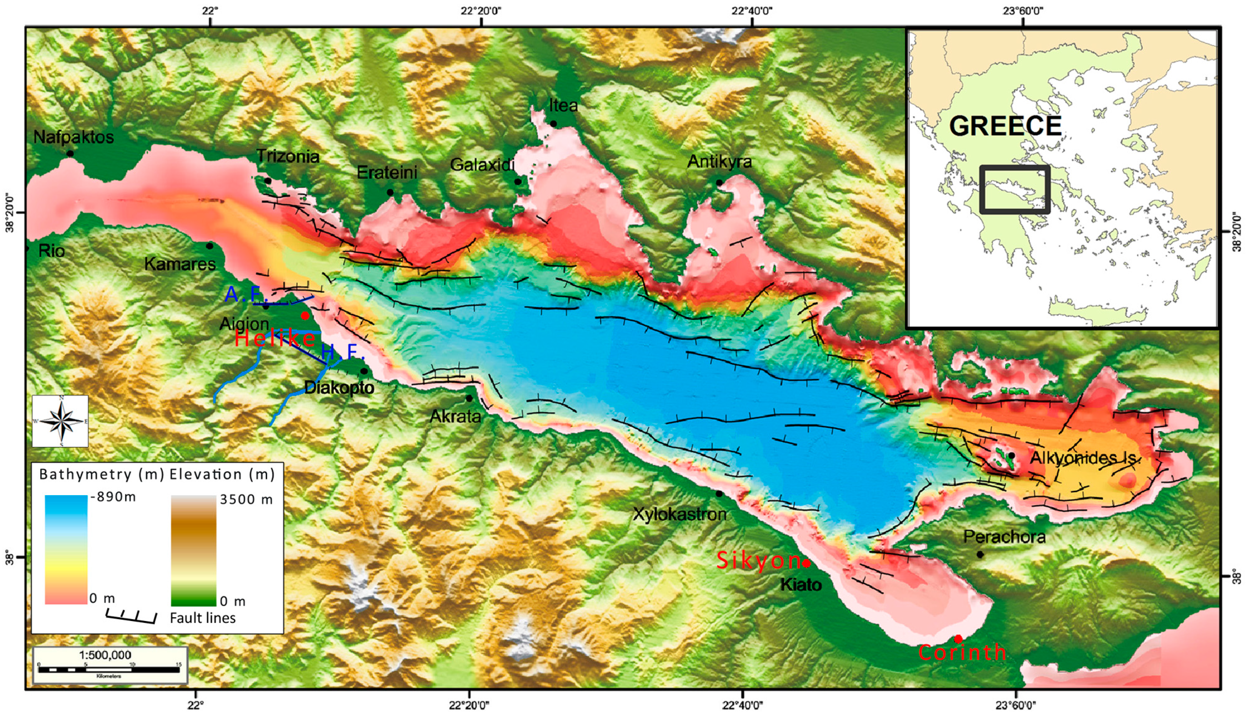
20], thus affecting the harbors of other important ancient cities of that time, such as Corinth and Sikyon (
Figure 1). However, such damage was not mentioned in any of the existing historical sources.
The submergence of Helike could not have been caused, either, by the activation of the Helike fault as suggested by Soter and Katsonopoulou [
6] because such a displacement would have been between 1.1 and 1.3 m and could not have caused enough subsidence in the coastal zone for the city to have been permanently submerged. Moreover, there is not any evidence that the Helike fault was activated at that time [
8]. This suggests that the earthquake responsible for the devastation of Helike was caused by the activation of another of the numerous faults in the Corinth Gulf.
The proposed earthquake model and the related translational slide as the natural forces behind the Helike catastrophe, based on the analysis of the slide, which affected the coastal and near-shore zone after the 6.2 R earthquake in 1995, appear to be better founded than those proposed by Marinatos [
4], Soter and Katsonopoulou [
7], and Soter
et al. [
11].


 ,
, 


