1. Introduction
The accurate spatial distribution and attributes (such as height, diameter at breast height (DBH), species, etc.) of trees are basic and important elements of forest inventories. With the rapid development of sensors, laser scanning techniques are more and more widely adopted to obtain such information for forest inventory, such as the aerial laser scanning (ALS) [
1], terrestrial laser scanning (TLS) and mobile laser scanning (MLS) [
2,
3]. In particular, MLS systems can improve the efficiency of field data collection. In addition, there are many recent studies on MLS systems and their accuracy [
4,
5,
6,
7].
The quality of the final data (the registered point cloud) based on MLS is related to the accuracy of position and attitude. Typically, position and attitude are provided by a positioning and orientation system (POS), which consists of an Inertial Navigation System (INS) and a Global Navigation Satellite System (GNSS), and the range is provided with a laser scanning sensor or MLS system [
8].
However, in a forest, the satellites are commonly blocked by the canopy, resulting in the loss of the GNSS signals, and serious multipath effects also result in degraded positioning accuracy. This degraded accuracy is one of the main limitations of using MLS in a forest. There are extensive experiments that evaluate GNSS or GNSS/INS positioning accuracy in forests. In general, with standalone GNSS, whether PPP (Precise Point Positioning) mode or RTK (Real-Time Kinematic) mode is used, positioning accuracies are at approximately the metre level in mature and dense forests [
9,
10,
11,
12,
13,
14]. With integrated GNSS/INS navigation systems, the positioning accuracy can improve to sub-meter-levels [
15]. However, an automatic high accuracy positioning solution that uses GNSS/INS is still not available for use in mature and dense forest environments.
SLAM constructs an environment map and determines the position of the mobile platform simultaneously. It was first proposed and investigated in the field of robotics in the 1980s. Most studies investigating SLAM are mainly for indoor environments, where GNSS is denied and which are full of features. Similarly, the application of SLAM to forests has been investigated in several studies [
16,
17,
18,
19,
20,
21,
22,
23,
24]. In addition, many of them have studied the feasibility of using SLAM technology for MLS in forests [
17,
18,
19]. However, forest environments are very different from indoor environments. There are rich and obvious features like lines and corners in indoor environments, and SLAM can acquire satisfactory solutions using feature matching methods. The features in forests are not continuous or stable, due to the density changes and the uneven terrain found in forests; moreover, GNSS satellites can be observed occasionally, particularly in open forest areas where SLAM cannot succeed in scan matching, leading to drift and gross errors [
16]. The main cause of these errors is incorrect estimation of the heading angle, because there are not enough features for scan matching. In addition, drift errors accumulate rapidly over time. At the same time, gross errors are introduced in the relative positions between adjacent epochs. In forests, although the positioning accuracy of traditional GNSS/INS is restricted, some valuable navigation information can be provided by GNSS/INS, because some of the satellites can still be observed. For example, the attitude and velocity can be estimated with high accuracy from fewer satellites. The accurate heading angle provided by GNSS/INS can correct the problems with drift in feature-poor environments, and the gross errors in relative positions can be controlled using the precise velocity estimates. Integrating these pieces of navigation information from GNSS/INS with SLAM can eliminate drift and gross errors and enhance positioning accuracy in forests.
Summarizing the above discussion, the navigation information used by an MLS system is provided by the GNSS/INS navigation system separately. In fact, an MLS system normally includes both a LiDAR sensor and a GNSS/INS system, so the two methods should be integrated to provide navigation information for the MLS system. The main contributions of this paper are as follows: (1) navigation information from GNSS/INS, more specifically the heading and the velocity parameters, are utilized in LiDAR-based SLAM positioning solutions to improve their accuracy and stability; (2) a heading angle aided (H-aided) SLAM method is proposed and succeeds in improving the SLAM positioning accuracy in a test carried out in a forest; and (3) a heading angle and velocity aided (HV-aided) SLAM method is proposed and utilized in a forest to improve the positioning accuracy further.
The remainder of this paper is organized as follows:
Section 2 describes the materials and methods utilized in this research;
Section 3 introduces the field tests; the experimental results are discussed in
Section 4; and
Section 5 draws conclusions.
2. Methods
2.1. GNSS/INS in GNSS-Challenged Environments
The tightly coupled integration passes pseudo-ranges, Doppler shifts, and other original carrier phases received by the GNSS receiver to a Kalman filter. When the number of visible satellites is between 0 and 4, Kalman filter measurement updating can limit the accumulation of INS errors. Therefore, this tightly coupled integration is suitable for urban canyons and other GNSS-degraded areas with fewer visible satellites. Past studies also showed that the tightly coupled integration has a stronger ability to resist gross errors [
25,
26]. The forest environment is similar to urban canyons, in that the number of visible satellites decreases because several satellites are blocked by tree crowns and serious errors are caused by the multipath effect. The tightly coupled integration may overcome these problems and obtain a guaranteed navigation solution in forests.
In this paper, GNSS/INS data are collected by a NovAtel SPAN system and processed using the Waypoint Inertial Explorer (IE) software package to obtain navigation solutions. The SPAN system is a GNSS/INS solution for obtaining continuous position, velocity and attitude information. By using INS data, in addition to GNSS, SPAN provides better position, velocity and attitude solutions which seamlessly bridge GNSS outages [
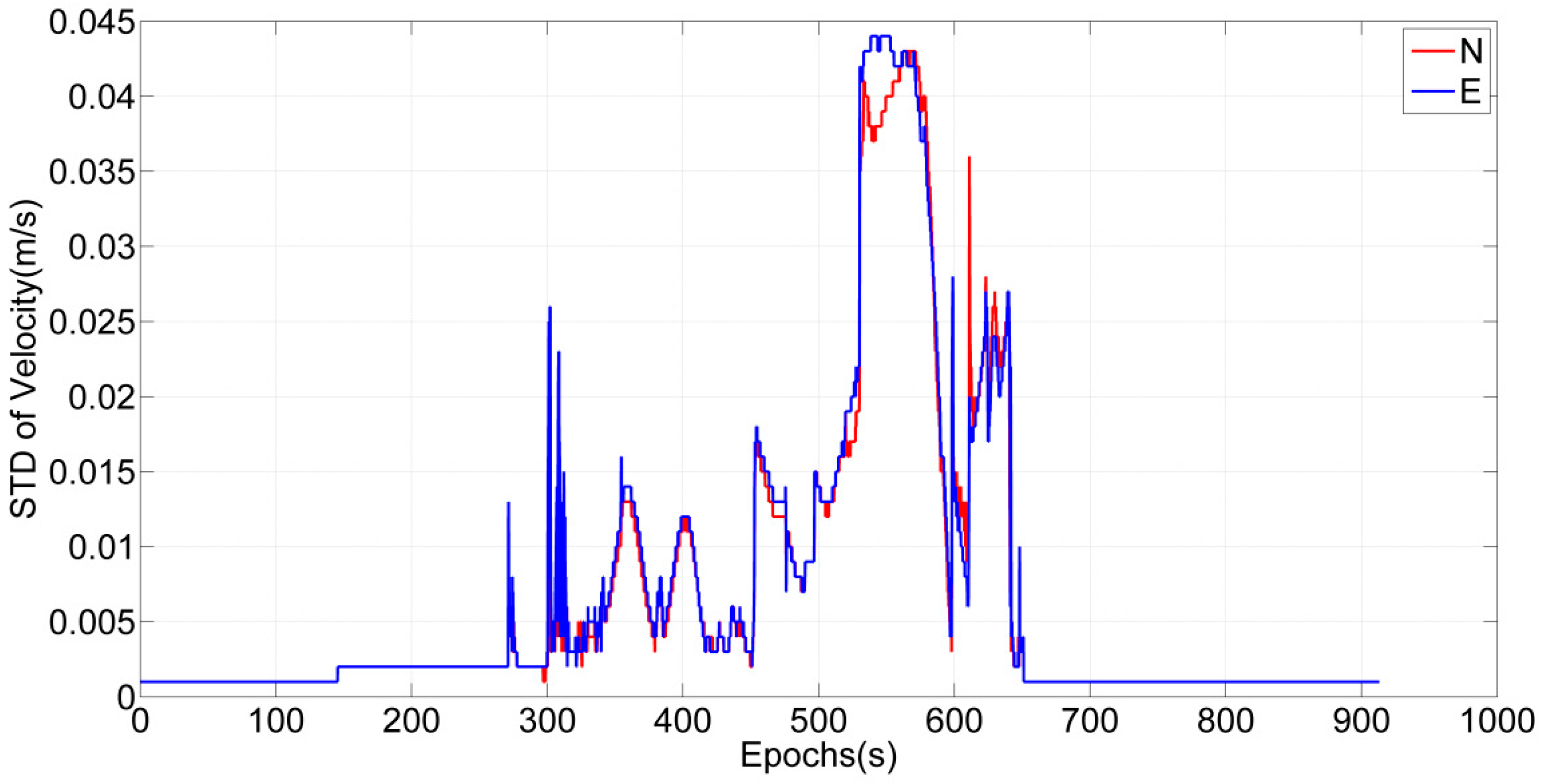
27]. The IE software package supports both loosely and tightly coupled integration models, which combine GNSS data from the base and the rover with INS data to conduct differential processing. In this process, bidirectional filtering and a variety of quality control methods are adopted to obtain high accuracy results. According to field tests by NovAtel, the root mean square error (RMSE) for velocity is at the centimetre/second level and the RMSE for attitude is less than 0.1 degree in all 3 axes in urban downtown areas [
27]. Similarly, our field test also yields velocity accuracy at the centimetre level in forest environments. As shown in
Figure 1, the standard deviation (STD) of velocity is less than 5 cm/s during this field test.
2.2. SLAM in Forest Areas
SLAM is a process of building and updating a map of an unknown environment based on data collected by range sensors [
28]. Of the current SLAM methods, LiDAR-based SLAM is widely used in positioning and environment-recognizing fields and has made a number of successful trials [
29].
In general, the classical method for laser scan matching is the Iterative Closest Point (ICP) algorithm [
30], which performs matching by minimizing the sum of distances between two clouds of points. There are many improvements on the classical ICP algorithm, such as Polar Scan Matching (PSM) [
31], the Iterative Closed Line (ICL) method [
32], etc. These methods mainly use consecutive pairs of scans for matching without using historical scans. Thus, the matching error will accumulate over time. Feature-based SLAM is an effective method. For example, Guivant and Nebot utilize Compressed Extended Kalman Filter (CEKF) SLAM in forested areas and compare the result with GPS ground truth [
23]. However, feature extraction and association increase the complexity. To improve this issue, the grid-map based method is proposed to process the laser scan matching. There is no feature extraction and feature data association process; all the previous scans are fully used in the grid-map based method. Generally, a grid-based occupancy likelihood map will be built based on all previous scans, and then the rigid-body transformation will be calculated by scan-to-map matching [
30]. One excellent grid-map based method is Maximum Likelihood Estimation (MLE) [
33]. Tang et al. [
16] employ the Improved Maximum Likelihood Estimation (IMLE) method for positioning in forests and obtain promising results in mature forests. In applying this method, a grid map is built based on probabilistic and feature uncertainty models, and then a brute-force search matching method is applied for scan-to-map matching to find the optimal rigid-body transformation. Because of the complexity of natural conditions in forests, features such as undergrowth trees and irregular rocks introduce noise into the point cloud data. More accurate initial values and search ranges will significantly improve the robustness of the brute–force search matching method, which indicates that integration with GNSS/INS navigation information may result in substantially improved positioning accuracy in forests. Therefore, in this paper, an algorithm for integrating GNSS/INS and IMLE-SLAM is studied to improve positioning accuracy in forests.
The IMLE-SLAM searches for the best body transformation to acquire the maximum likelihood value:
where
is the optimal body transformation;
is the likelihood map, which stores likelihood values built by previous scans; and
is the current scan. The detailed process and performance of IMLE-SLAM can be found in [
33].
Moreover, some premises that are the same as in [
16] have been taken into account, which are that multiple segmental laser scans from 3D space are projected onto 2D stem profiles to generate the stem map according to the accurate roll and pitch estimates from GNSS/INS by assuming that most mature stems have straight and circular stems. Because the main type of tree in the field test is upright pine trees, the 2D projection assumption is reasonable in our experiment.
2.3. Instrumentation
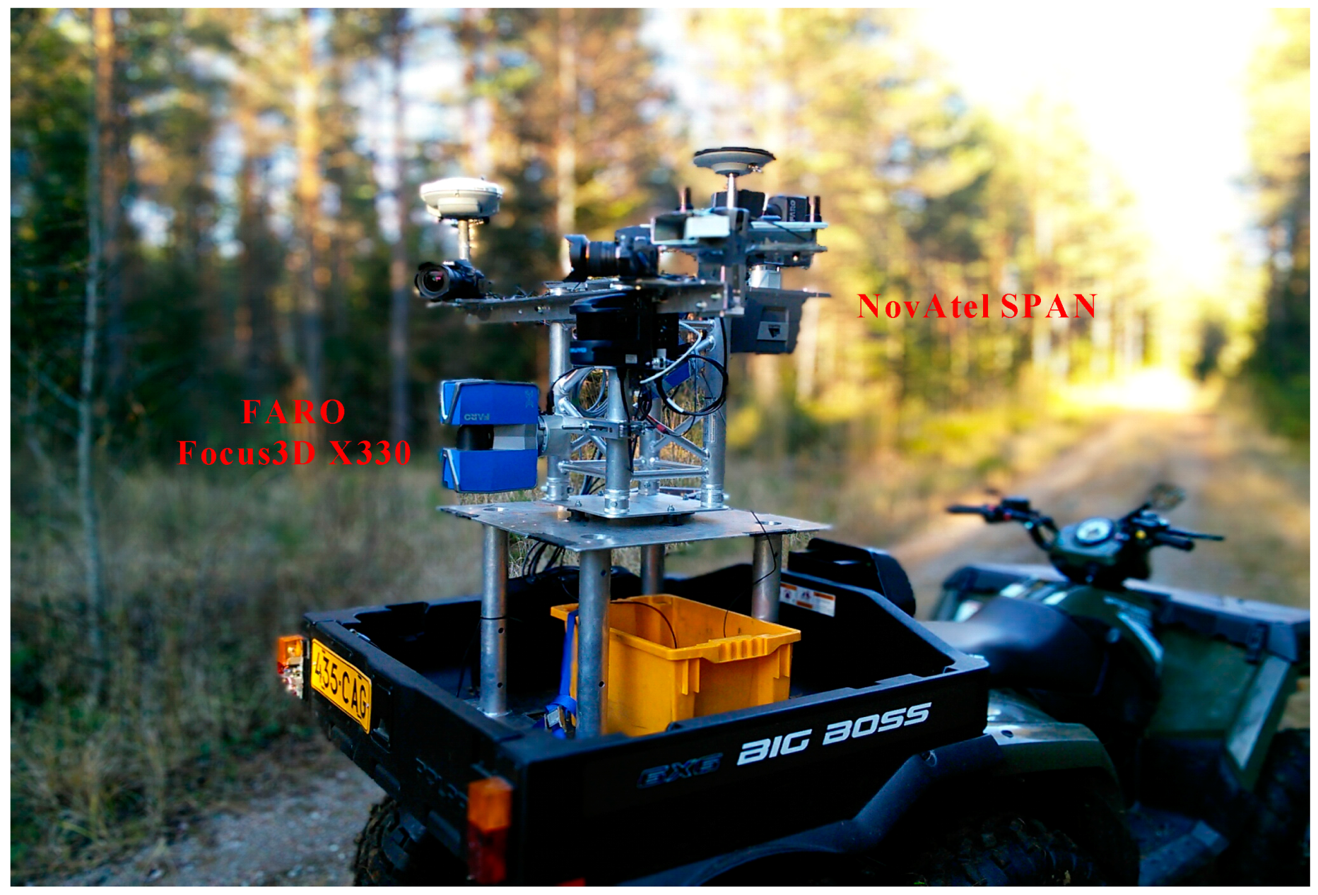
The research is based on the self-developed FGI ROAMER R2 mobile mapping system installed on an all-terrain-vehicle (ATV) and shown in
Figure 2. The GNSS/INS part of this MLS system is a NovAtel Synchronized Position Attitude Navigation (SPAN) navigation system, which consists of a GNSS receiver (NovAtel Flexpak6) and an INS system (NovAtel UIMU-LCI). The LiDAR sensor adopted for SLAM research is a horizontally mounted FARO Focus3D X330, which can generate approximately 1 million points per second. All sensors are mounted on a rigid platform made of hard aluminium. The beam divergence of the FARO Focus3D X330 is 0.011°, and the beam diameter at exit is 2.25 mm. The maximum valid range measurement utilized in this research is 25 m, resulting in a maximum footprint size of 7.3 mm, compared to 10–20 cm for models with large beam divergence at the same distance. The synchronized pulse of the LiDAR is utilized to trigger an event pin of the GNSS/INS device to obtain synchronization [
16]. The detailed technical specifications of the GNSS/INS navigation system and the laser scanner can be found in [
15]. The raw laser point cloud data in a scanner coordinate system are transformed to real world coordinates using the vehicle position and attitude fetched from the GNSS/INS. Therefore, the accuracy of the point cloud is dependent on the accuracy of the position and attitude measurements from the GNSS/INS.
2.4. Integration Method in Forests
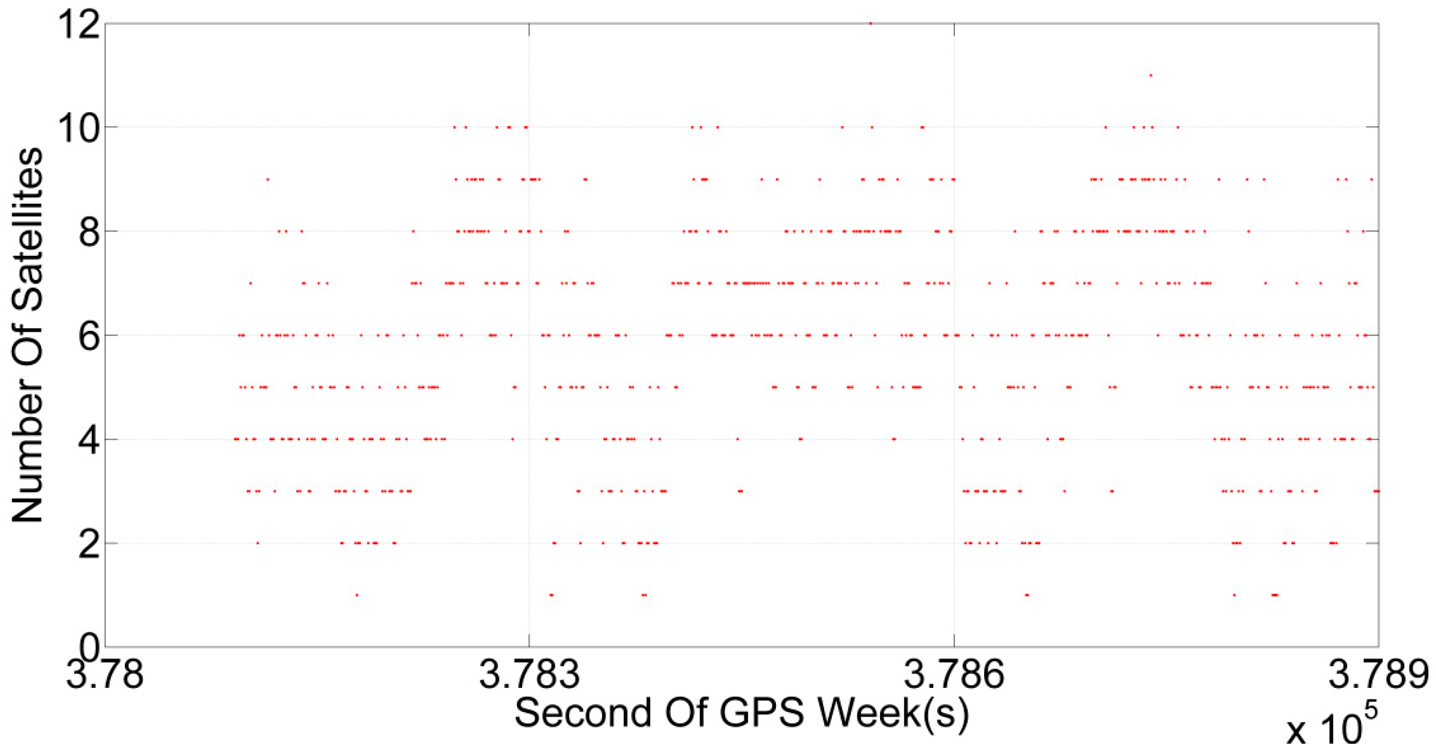
As mentioned above, the forest environment is similar to the urban canyon environment. The satellite signal is blocked. The number of visible satellites is unstable, as shown in
Figure 3, but not all the satellites are completely lost. This fact implies that a tightly coupled integration of GNSS/INS can effectively conduct measurement updates to suppress error accumulation over time, although the positioning accuracy will be affected and degraded, due to the reduced number of visible satellites and serious multipath effects. However, velocity and attitude estimates can still be obtained at a high level of accuracy.
The IMLE-SLAM method is based on the maximum posterior probability criterion. The brute-force search method is applied to calculate the posterior probability of the current scan based on the grid map. The map is built up of previous scans with different body transformations. Because IMLE-SLAM finds the maximum posterior probability corresponding to the optimal body transformation, it is able to obtain centimetre-level positioning accuracy for long-term operation in indoor environments [
33] and produce a more accurate and clearer tree trunk map, which is beneficial for extracting tree trunk information such as DBH [
16]. However, IMLE-SLAM also has drawbacks. It is strongly dependent on the features in the environment. In a two-dimensional coordinate system, a body transformation includes two position parameters and one heading angle parameter, which means a three-dimensional search scope. The high-dimensional search scope also reduces the robustness of the algorithm. If the posterior probability is regarded as a function of position and heading angle, the brute-force search method searches for the function extremum within a certain region of three-dimensional space. However, due to the complexity of the environment and noise effects, there may be a plurality of extreme points in an inappropriate search scope. The influence of these disadvantages will be enlarged in the forest. If the dimension of the search scope can be reduced, the robustness and computational efficiency will be improved greatly. As a result, a more precise search scope will reduce the effects of noise in the environment.
It can be seen that strong complementarity between GNSS/INS and IMLE-SLAM exists. Although the accuracy of GNSS/INS positioning in forests is only sub-metre or even metre, the heading angle is accurate enough for IMLE-SLAM, and the precise velocity estimates can provide accurate relative displacements over short time intervals, as reported in [
34].
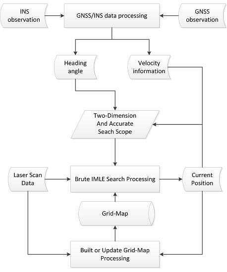
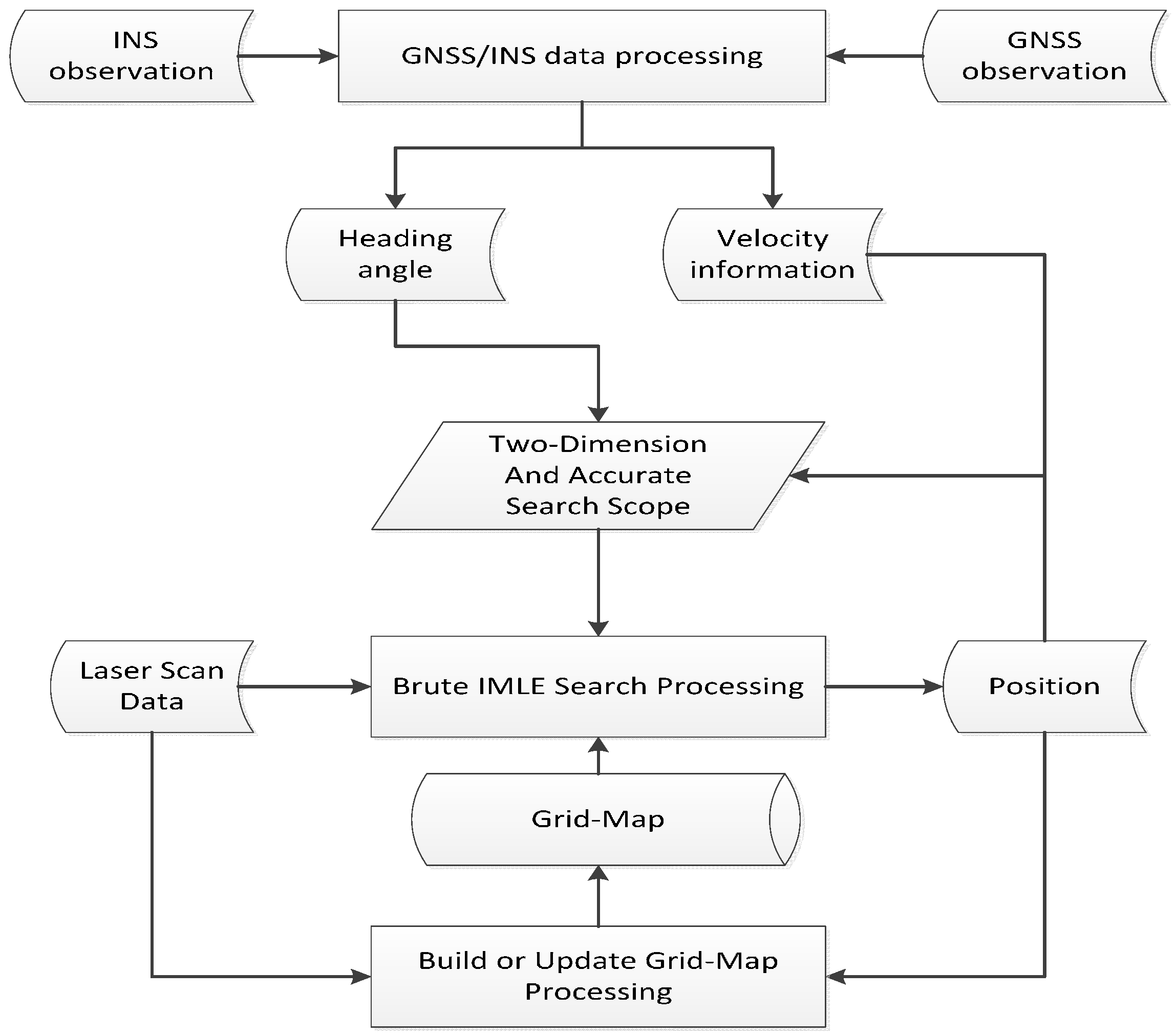
IMLE-SLAM can use the heading angle from GNSS/INS to reduce the dimension of the search scope, and obtains a more restricted search scope using precise relative displacements obtained with a high data sampling rate. The workflow of the data processing in integrating GNSS/INS and IMLE-SLAM is shown in
Figure 4. First, GNSS and INS data are processed to obtain velocity and heading angle estimates over time. When matching laser scan data during one epoch, the heading angle is regarded as a known parameter and input into the brute-force IMLE search process, and the velocity is integrated over the epoch interval. The displacement is then added to the estimated position from the last epoch to obtain the initial position of the current epoch, which constitutes the search scope with some position uncertainty. The uncertainty is mainly determined by the maximum resolution of the grid map. Supposing the size of the grid cells where the grid map’s resolution is highest is
, the search scope ranges from negative
to
on each component, centred on the initial position. The search scope of
in Equation (1) can then be written as follows:
where
is the heading angle estimated by GNSS/INS, and
and
represent the initial position as estimated using the velocity from GNSS/INS.
3. Field Test
In this paper, field tests were carried out in Evo, Southern Finland (61°19′N, 25°11′E). The area lies within the southern boreal forest zone. The dominant tree species are Scots pine and Norway spruce. Detailed information on this test field can be found in [
16].
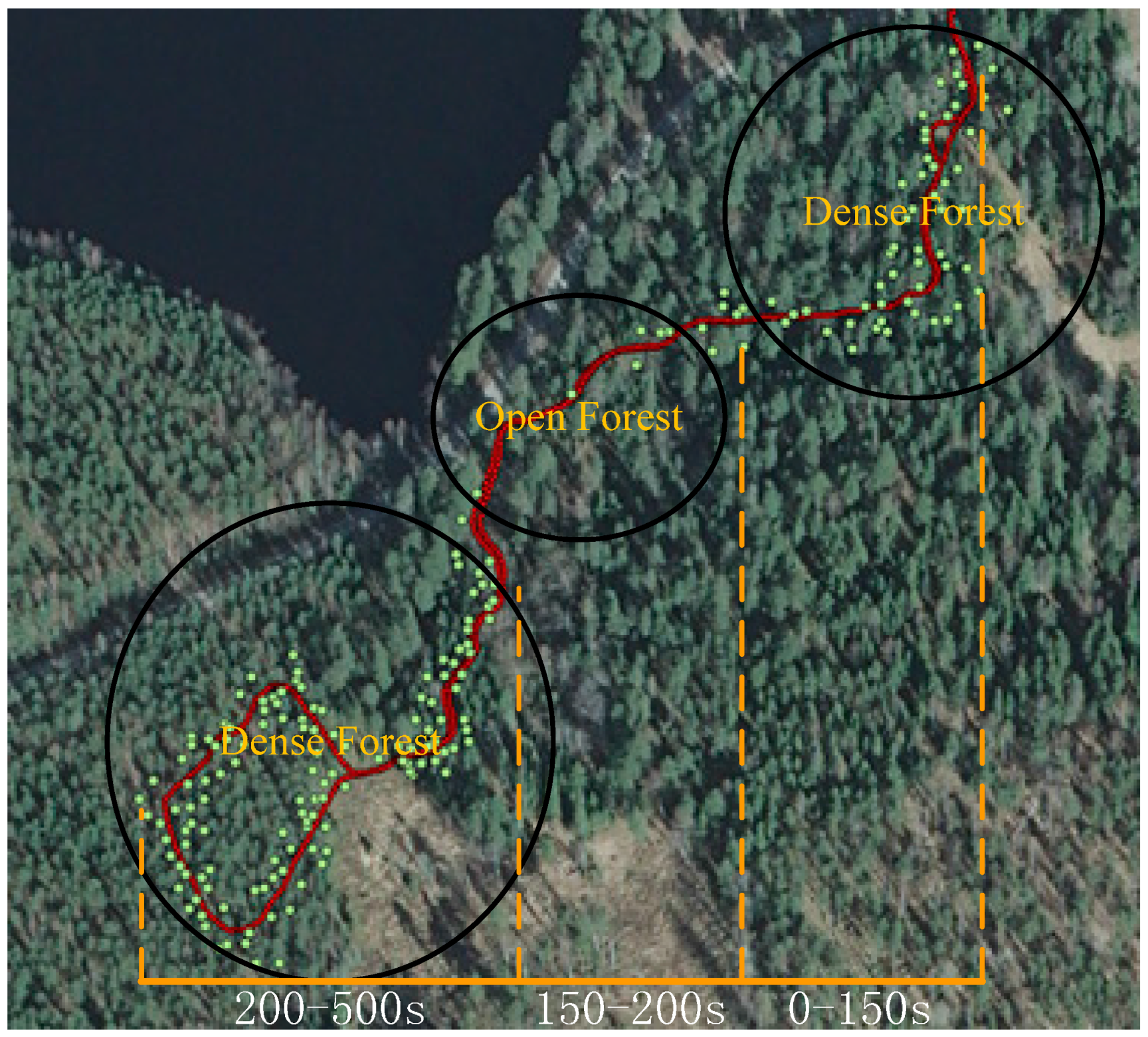
In the field area, there are 224 trees that were measured to the centre of the stem at breast height by a total station and RTK GNSS. The accuracies of the reference trees’ positions are better than 10 cm. The positions of these trees in a 2D coordinate system are precisely estimated as the reference targets to evaluate the positioning accuracy. When the ROAMER R2 mobile mapping system passed through this field, GNSS/INS observations and laser scan measurements were recorded. Then, the laser point cloud was calculated based on the position and attitude of MLS, from which the positions of the reference trees could be extracted. The accuracy of the position and attitude estimates from MLS could be evaluated by comparing the positions of these trees with the reference positions directly. In the field tests, the average driving speed of the ATV was approximately 4 km/h and the length of the trajectory was approximately 800 m. The reference trees and the vehicle trajectory are shown in
Figure 5.
The field test can be divided into three parts. It starts in dense forest, and after approximately 150 s enters open forest, and after approximately 50 s enters another dense forest area. In dense forest, SLAM can take advantage of the large number of features for scan matching where the signals of satellites are blocked seriously, which will result in the positioning accuracy degeneration of GNSS/INS. In contrast, in open forest, SLAM may introduce errors because of the feature-poor environment, while GNSS/INS will work well because it has enough visible satellites.
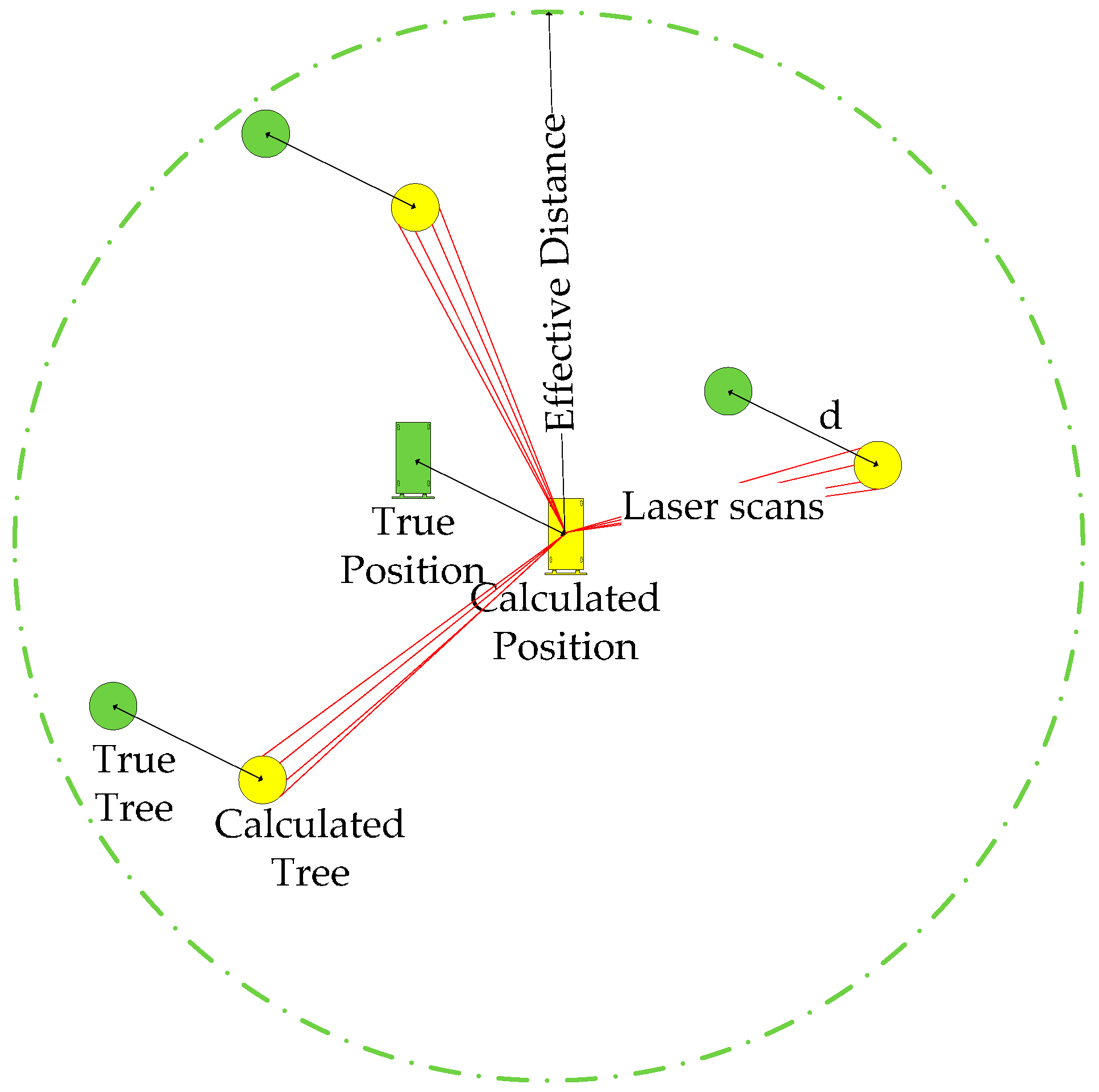
The mapping and positioning results are evaluated using the reference trees because the reference trajectory cannot be observed directly during the field test. The positions of the reference trees are estimated from the generated stem distribution map, which is built from the laser point cloud data. The accuracy of position can be evaluated by the comparison with the positions of the reference trees. The positioning accuracy during a single epoch is calculated using the position errors of the reference trees located within the effective LiDAR range. It is a circle centred on the calculated platform position and has a radius of LiDAR’s effective range (25 m in this experiment), as shown in
Figure 6. The RMSE of the position error is calculated from the reference tree network as
where
is the offset of the centre of the
-th reference tree within the effective LiDAR range.
4. Results and Discussion
4.1. Separate Evaluation of GNSS/INS and IMLE-SLAM Methods
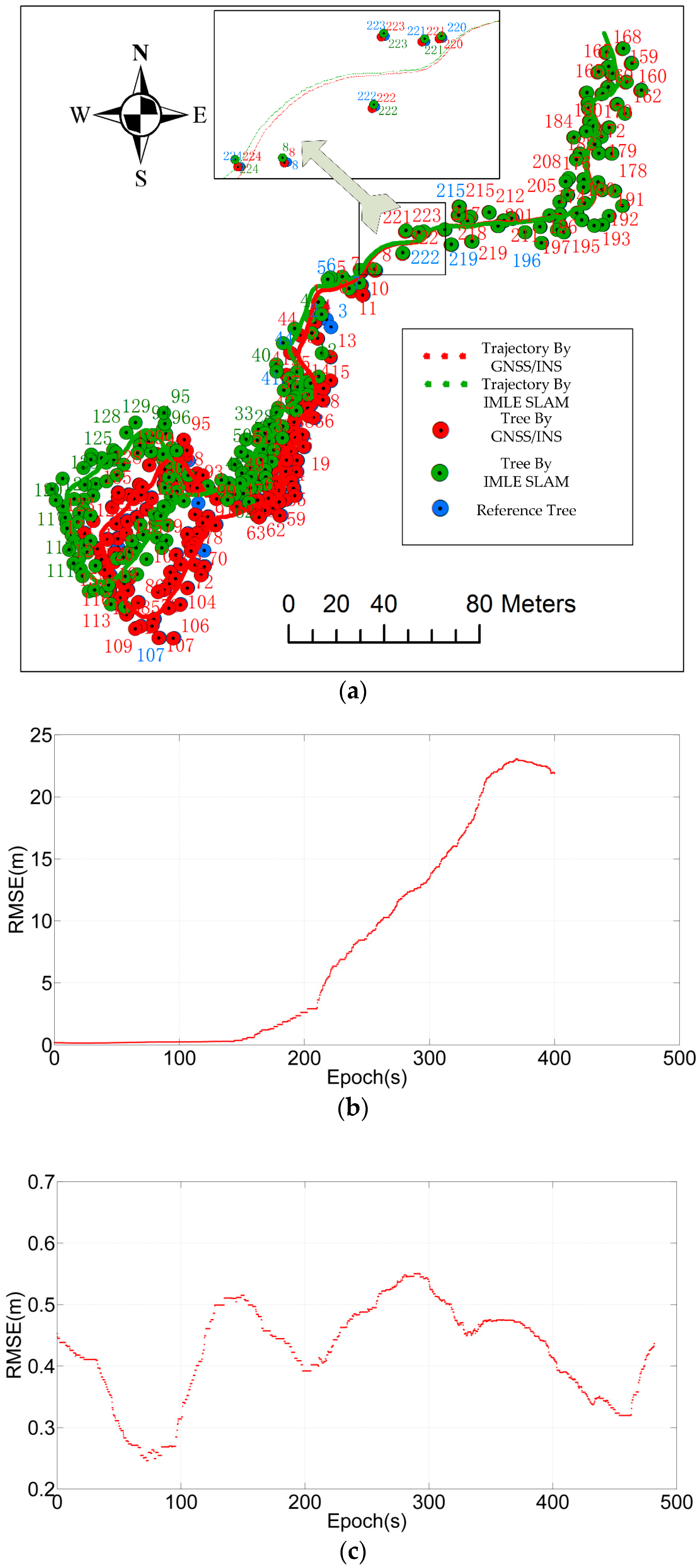
The trajectories and stem positions estimated using the GNSS/INS and IMLE-SLAM methods are compared in
Figure 7a for the entire test. The RMSEs of the trajectory position errors from the GNSS/INS and IMLE-SLAM methods for the entire test are presented in
Figure 7b,c, respectively.
As shown in
Figure 7a, the IMLE-SLAM solution is effective in the dense forest, where the position errors are moderated. However, in the open forest, the position errors accumulate quickly and cannot be mitigated even when driving back to the dense forest again. The GNSS/INS solution is continuous and stable in the entire test with sub-meter position errors. The RMSEs of GNSS/INS and IMLE-SLAM position trajectory are given in
Table 1.
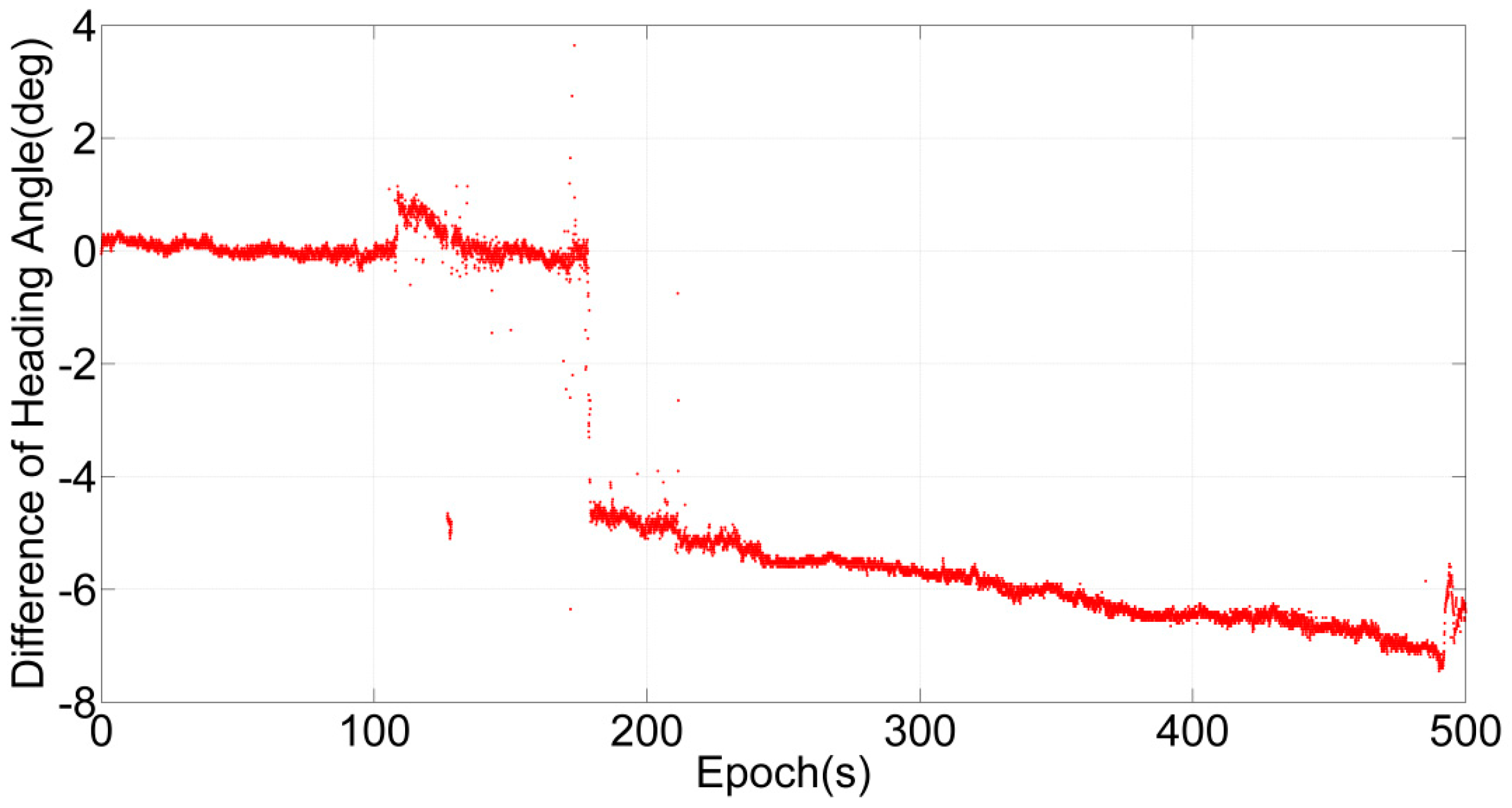
As shown in
Figure 8, the heading angle estimated by IMLE-SLAM is unstable compared with that estimated by GNSS/INS. It can be observed that there are some jump errors between the epochs at 100 s and 200 s, when the ATV drove out of the mature forest and into the open forest. Heading angle errors leads to large positioning errors. Therefore, when both heading angle and position are estimated in IMLE-SLAM, the dependence on the environmental features will be much higher. In addition, once the heading angle is estimated incorrectly, enormous errors will be introduced into the estimation of position, as illustrated in
Figure 7b and
Table 1.
The heading angle error of IMLE-SLAM accumulates quickly due to the smaller number of features in the open forest, leading to position errors. The estimation of heading angle is a weakness of the SLAM algorithm, which depends heavily on the number and conspicuousness of features and is sensitive to noise [
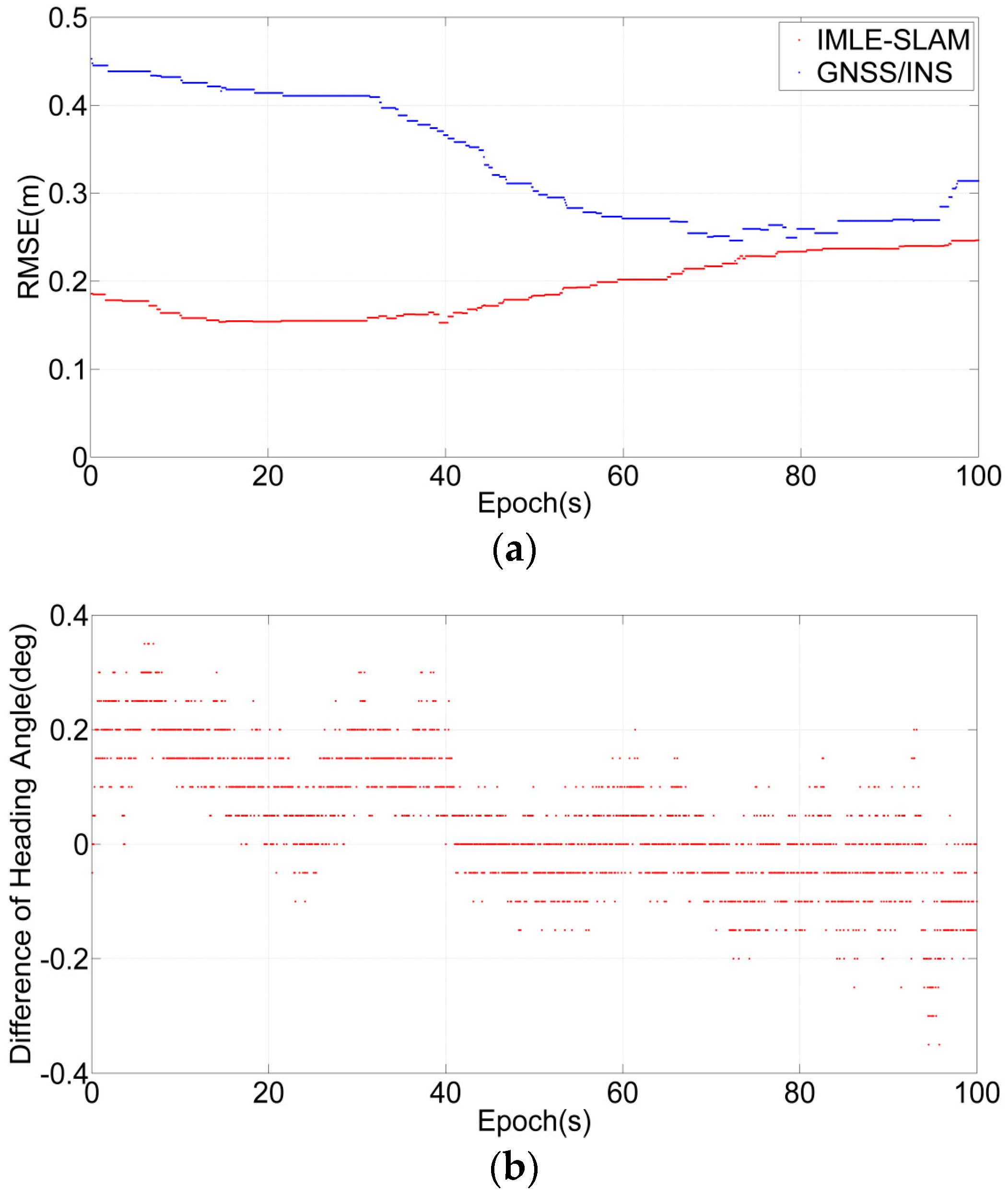
35]. If searching for the heading angle, the dimension of the search scope will be higher, this will greatly increase the instability of the algorithm, especially in complex environments. Moreover, it reduces the accuracy of the eventual position estimates. However, the performance is degraded in open forest with IMLE-SLAM, compared to its moderate performance in the mature forest. The statistics of position error of IMLE-SLAM and GNSS/INS method in the first dense forest area is shown in
Figure 9a, the heading angle difference in the first dense forest area is shown in
Figure 9b, and the RMSEs of the GNSS/INS and IMLE-SLAM position trajectories in the dense forest are given in
Table 2.
As shown in
Figure 9a, that the positioning accuracy of IMLE-SLAM is higher than GNSS/INS in the dense forest. At the same time, the heading angles of IMLE-SLAM and GNSS/INS are in good agreement, as shown in
Figure 9b. However, the difference in the IMLE-SLAM heading angle compared with GNSS/INS is still larger than 0.1 degrees in some periods. The reason might be that, the angular resolution of LiDAR limits the accuracy of the heading angle. The accurate heading angles estimated by GNSS/INS can be integrated with IMLE-SLAM to improve the positioning accuracy.
4.2. Results from the IMLE-SLAM Method Aided by Heading Angle
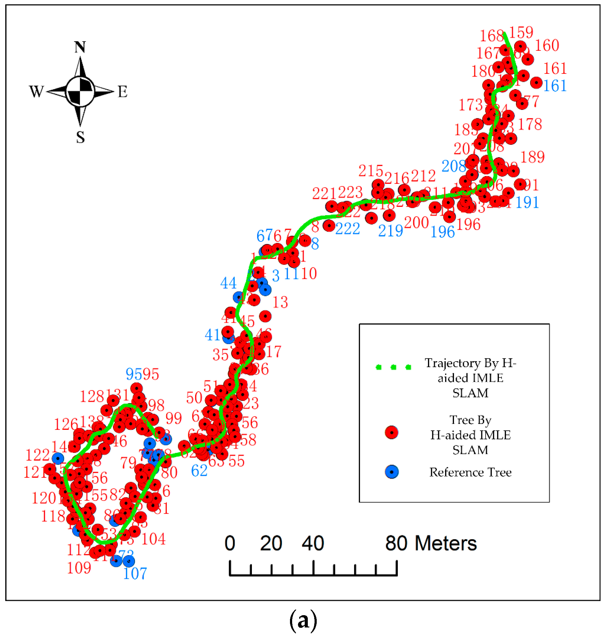
After supplying heading angle information from GNSS/INS to IMLE-SLAM, also called H-aided IMLE-SLAM, the dimensionality of the search scope decreases from three dimensions to two. The trajectories and tree stem positions of the entire test are shown in
Figure 10a. In addition, the RMSE of position trajectory for the entire test is presented in
Figure 10b.
As shown in
Figure 10, when the heading angle from GNSS/INS is integrated with the IMLE-SLAM algorithm, the rapid drift does not appear when entering the open forest area. IMLE-SLAM can obtain a highly accurate trajectory over the entire test. Compared with the positioning accuracy from GNSS/INS, the positioning accuracy of H-aided IMLE-SLAM is improved significantly. The RMSEs of the eastings and northings are 0.12 m and 0.05 m and are improved by nearly 66.7% and 75%, respectively. The horizontal accuracy is 0.13 m and is improved by nearly 70%.
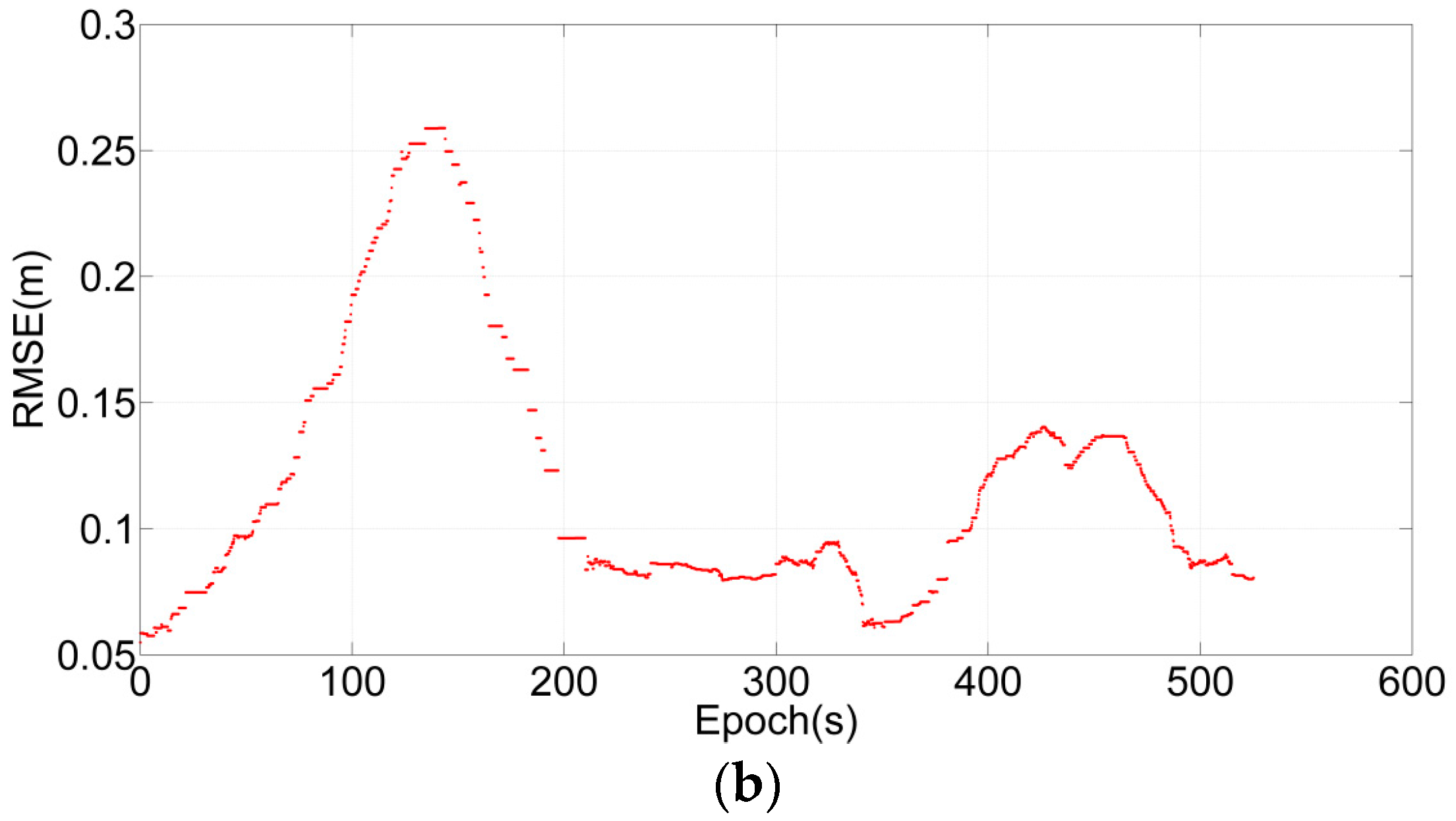
4.3. Result of IMLE-SLAM Method Aided by Heading Angle and Velocity
By integrating heading angle information, the IMLE-SLAM algorithm has been greatly improved. However, it can still be observed that the position error in the open forest increased. As shown in
Figure 10b, though the accuracy recovers after re-entering the dense forest, the stem position in the open forest is inaccurate due to the position error. The reason is that the real position cannot be searched out, even after the dimension is reduced using the heading angle in the feature-poor environment. Under normal circumstances, the optimal position is identified within a certain search scope range. The range is an empirical value based on the position from the previous epoch, which is generally coarse. When processing a feature-poor data frame with many noisy points, such search scopes can easily lead to false optimum positions, as described in
Section 2.4.
By supplying the velocity estimated by GNSS/INS, a narrower search scope range that contains the true position can be calculated from the velocity and the position of last epoch, as described in
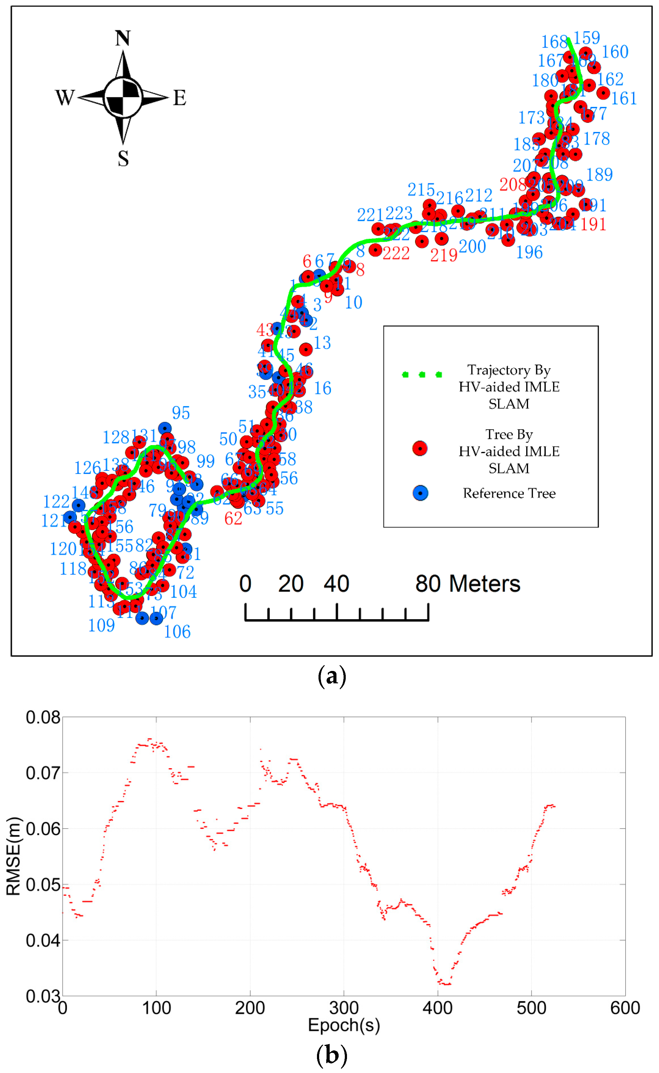
Section 2.4. The brute-force search method can easily find the optimal position corresponding to a maximum likelihood score. The trajectories and the stem positions of the heading angle and velocity-aided (HV-aided) IMLE-SLAM methods are shown in
Figure 11a. In addition, the trajectory RMSE of HV-aided IMLE-SLAM is presented in
Figure 11b.
As seen from
Figure 11, when the velocity from GNSS/INS is additionally used to provide a more narrow and precise search scope for the MLE-SLAM algorithm, the large positioning errors due to the reduced prevalence of features in the open forest area between 100 s and 200 s are mitigated and a more accurate position trajectory can be obtained. The RMSEs of the eastings and northings are 0.04 m and 0.04 m. The horizontal accuracy is 0.06 m and improved by 86% relative to GNSS/INS, which means a more accurate stem map. The results show that the positioning accuracy of HV-aided IMLE-SLAM reaches the centimetre level.
5. Conclusions
In summary, position and attitude play an important role in the use of MLS for forest mapping. Traditionally, position and attitude determinations have mainly relied on GNSS/INS systems, which can only achieve sub-meter positioning accuracy in forests. The SLAM method has recently been examined for its potential in providing navigation information and has achieved some promising results. Most SLAM algorithms are utilized in indoor environments and are integrated only with INS. GNSS/INS navigation information is rarely utilized in SLAM methods. In contrast to the indoor environment, the forest environment is much more complex, and only some satellites can be used for observation. However, highly precise attitude and velocity information can be obtained using GNSS/INS. In addition, the SLAM method can only provide good results in feature-rich forests, and does not perform well in feature-poor open forests. The highly precise attitude and velocity information from GNSS/INS can be integrated with SLAM to improve its robustness and accuracy for high-precision positioning in forests.
Field test results showed that when standalone IMLE-SLAM is used in dense forest, heading angles can be estimated correctly, and the horizontal accuracy of position is decimetre-level and better than the standalone GNSS/INS method, but navigation fails in open forest areas because heading angle error leads to large positioning error. When integrated with high-precision heading angle estimates from GNSS/INS, the H-aided IMLE-SLAM can successfully obtain guaranteed positioning results for the entire test; the horizontal accuracy of the entire trajectory is 0.13 m and significantly improved (by 70%) compared to that of GNSS/INS. However, positioning error in the open forest is still greater than that in dense forest. When high-precision velocity data are additionally included, the positioning accuracy of HV-aided IMLE-SLAM in open forest is greatly improved. The horizontal accuracy of the entire trajectory reaches 0.06 m, which is improved by 86% relative to GNSS/INS. The results show that the integration of GNSS/INS with SLAM yields a high-precision navigation method in forest that can obtain more accurate stem maps.
Although the devices used herein are relatively expensive and therefore display better performance, the integration methods may also be applicable to low-cost equipment. Therefore, our future work will study the possibility of applying this integration method to low-cost equipment.
Acknowledgments
This study was financially supported by the National Key Research and Development Plan (No. 2016YFB0501803, No. 2016YFB0502202 and No. 2016YFB0800405); two Finnish Academy projects, “Towards Precision Forestry” and “Centre of Excellence in Laser Scanning Research (CoE-LaSR) (272195)”; the National Natural Science Foundation of China (41304004); the Chinese Academy of Science (181811KYSB20130003); and the Chinese Ministry of Science and Technology (2015DFA70930).
Author Contributions
Chuang Qian and Jian Tang conceived and designed the experiments, wrote the paper, and performed the experiments; Harri Kaartinen and Antero Kukko performed the field test and provided the LiDAR, IMU, and GPS raw data and tree reference data; and Yuwei Chen, Hui Liu Lingli Zhu, Xinlian Liang, Liang Chen and Juha Hyyppä reviewed the paper and gave constructive advice.
Conflicts of Interest
The authors declare no conflict of interest.
References
- Hyyppä, J.; Holopainen, M.; Olsson, H. Laser scanning in forests. Remote Sens. 2012, 4, 2919–2922. [Google Scholar] [CrossRef]
- Leeuwen, M.; Nieuwenhuis, M. Retrieval of forest structural parameters using LiDAR remote sensing. Eur. J. For. Res. 2010, 129, 749–770. [Google Scholar] [CrossRef]
- Liang, X.; Kankare, V.; Hyyppä, J.; Wang, Y.; Kukko, A.; Haggrén, H.; Yu, X.; Kaartinen, H.; Jaakkola, A.; Guan, F.; et al. Terrestrial laser scanning in forest inventories. ISPRS J. Photogramm. Remote Sens. 2016, 115, 63–77. [Google Scholar] [CrossRef]
- Liang, X.; Kukko, A.; Kaartinen, H.; Hyyppä, J.; Yu, X.; Jaakkola, A.; Wang, Y. Possibilities of a personal laser scanning system for forest mapping and ecosystem services. Sensors 2014, 14, 1228–1248. [Google Scholar] [CrossRef] [PubMed]
- Rutzinger, M.; Pratihast, A.K.; Oude Elberink, S.; Vosselman, G. Detection and modelling of 3D trees from mobile laser scanning data. ISPRS Int. Arch. Photogramm. Remote Sens. Spat. Inf. Sci. 2010, 38, 520–525. [Google Scholar]
- Holopainen, M.; Kankare, V.; Vastaranta, M.; Liang, X.; Lin, Y.; Vaaja, M.; Yu, X.; Hyyppä, J.; Hyyppä, H.; Kaartinen, H.; et al. Tree mapping using airborne, terrestrial and mobile laser scanning—A case study in a heterogeneous urban forest. Urban For. Urban Green. 2013, 12, 546–553. [Google Scholar] [CrossRef]
- Kukko, A.; Kaartinen, H.; Hyyppä, J.; Chen, Y. Multiplatform mobile laser scanning: Usability and performance. Sensors 2012, 12, 11712–11733. [Google Scholar] [CrossRef]
- Bauwens, S.; Bartholomeus, H.; Calders, K.; Lejeune, P. Forest inventory with terrestrial LiDAR: A comparison of static and hand-held mobile laser scanning. Forests 2016, 7, 127. [Google Scholar] [CrossRef]
- Andersen, H.E.; Clarkin, T.; Winterberger, K.; Strunk, J. An accuracy assessment of positions obtained using survey-and recreational-grade global positioning system receivers across a range of forest conditions within the Tanana Valley of interior Alaska. West. J. Appl. For. 2009, 24, 128–136. [Google Scholar]
- Danskin, S.D.; Bettinger, P.; Jordan, T.R.; Cieszewski, C. A comparison of GPS performance in a Southern hardwood forest: Exploring low-cost solutions for forestry applications. South. J. Appl. For. 2009, 33, 9–16. [Google Scholar]
- Bakuła, M.; Oszczak, S.; Pelc-Mieczkowska, R. Performance of RTK positioning in forest conditions: Case study. J. Surv. Eng. 2009, 135, 125–130. [Google Scholar] [CrossRef]
- Bakula, M.; Przestrzelski, P.; Kazmierczak, R. Reliable technology of centimeter GPS/GLONASS surveying in forest environments. IEEE Trans. Geosci. Remote Sens. 2015, 53, 1029–1038. [Google Scholar] [CrossRef]
- Tachiki, Y.; Yoshimura, T.; Hasegawa, H.; Mita, T.; Sakai, T.; Nakamura, F. Effects of polyline simplification of dynamic GPS data under forest canopy on area and perimeter estimations. J. For. Res. 2005, 10, 419–427. [Google Scholar] [CrossRef]
- Ucar, Z.; Bettinger, P.; Weaver, S.; Merry, K.L.; Faw, K. Dynamic accuracy of recreation-grade GPS receivers in Oak-hickory forests. Forestry 2014, 87, 504–511. [Google Scholar] [CrossRef]
- Kaartinen, H.; Hyyppä, J.; Vastaranta, M.; Kukko, A.; Jaakkola, A.; Yu, X.; Pyörälä, J.; Liang, X.; Liu, J.; Wang, Y.; et al. Accuracy of kinematic positioning using global satellite navigation systems under forest canopies. Forests 2015, 6, 3218–3236. [Google Scholar] [CrossRef]
- Tang, J.; Chen, Y.; Kukko, A.; Kaartinen, H.; Jaakkola, A.; Khoramshahi, E.; Hakala, T.; Hyyppä, J.; Holopainen, M.; Hyyppä, H. SLAM-aided stem mapping for forest inventory with small-footprint mobile LiDAR. Forests 2015, 6, 4588–4606. [Google Scholar] [CrossRef]
- Ringdahl, O.; Hohnloser, P.; Hellström, T.; Holmgren, J.; Lindroos, O. Enhanced algorithms for estimating tree trunk diameter using 2D laser scanner. Remote Sens. 2013, 5, 4839–4856. [Google Scholar] [CrossRef]
- Takashi, T.; Asano, A.; Mochizuki, T.; Kondou, S.; Shiozawa, K.; Matsumoto, M.; Tomimura, S.; Nakanishi, S.; Mochizuki, A.; Chiba, Y.; et al. Forest 3D mapping and tree sizes measurement for forest management based on sensing technology for mobile robots. In Proceedings of the International Conference on Field and Service Robotics (FSR2012), Matsushima, Japan, 16–18 July 2012; pp. 357–368.
- Ding, X.; Yan, L.; Liu, J.; Kong, J.; Yu, Z. Obstacles detection algorithm in forest based on multi-sensor data fusion. J. Multimed. 2013, 8, 790–795. [Google Scholar] [CrossRef]
- Öhman, M.; Miettinen, M.; Kannas, K.; Jutila, J.; Visala, A.; Forsman, P. Tree measurement and simultaneous localization and mapping system for forest harvesters. In Proceedings of the International Conference on Field and Service Robotics (FSR2007), Chamonix, France, 9–12 July 2007; pp. 369–378.
- Miettinen, M.; Ohman, M.; Visala, A.; Forsman, P. Simultaneous localization and mapping for forest harvesters. In Proceedings of the IEEE International Conference on Robotics and Automation (ICRA2007), Roma, Italy, 10–14 April 2007; pp. 517–522.
- Chen, Y.; Tang, J.; Hyyppä, J.; Holopainen, M.; Liang, X.; Liu, J.; Chen, L.; Hakala, T.; Litkey, P.; Niu, X.; et al. Automated stem mapping using slam technology for plot-wise forest inventory. In Proceedings of the Ubiquitous Positioning Indoor Navigation and Location-Based Services(UPINLBS2014), Corpus Christi, TX, USA, 20–21 November 2014; pp. 130–134.
- Guivant, J.; Nebot, E. Improving computational and memory requirements of simultaneous localization and map building algorithms. In Proceedings of the IEEE International Conference on Robotics and Automation (ICRA2002), Washington, DC, USA, 11–15 May 2002; pp. 2731–2736.
- Ryding, J.; Williams, E.; Smith, M.J.; Eichhorn, M.P. Assessing handheld mobile laser scanners for forest surveys. Remote Sens. 2015, 7, 1095–1111. [Google Scholar] [CrossRef]
- Godha, S. Performance Evaluation of Low Cost MEMS-based IMU Integrated with GPS for Land Vehicle Navigation Application. Master’s Thesis, Department of Geomatics Engineering, University of Calgary, Calgary, AB, Canada, February 2006. [Google Scholar]
- Petovello, M.G. Real-Time Integration of A Tactical-Grade IMU and GPS for High-Accuracy Positioning and Navigation. Ph.D. Thesis, Department of Geomatics Engineering, University of Calgary, Calgary, AB, Canada, April 2003. [Google Scholar]
- Kennedy, S.; Hamilton, J.; Martell, H. Architecture and system performance of SPAN NovAtel’s GPS/INS solution. In Proceedings of the ION PLANS 2006, San Diego, CA, USA, 25–27 April 2006; pp. 23–25.
- Bailey, T.; Durrant-Whyte, H. Simultaneous localization and mapping (SLAM): Part II. IEEE Robot. Autom. Mag. 2006, 13, 108–117. [Google Scholar] [CrossRef]
- Li, L.; Yao, J.; Xie, R.; Tu, J.; Feng, C. Laser-based SLAM with efficient occupancy likelihood map learning for dynamic indoor scenes. In Proceedings of the ISPRS Annals of Photogrammetry, Remote Sensing and Spatial Information Sciences (ISPRS Annals), Prague, Czech Republic, 12–19 July 2016; pp. 119–126.
- Besl, P.J.; McKay, N.D. Method for registration of 3-D shapes. IEEE Trans. Pattern Anal. Mach. Intell. 1992, 14, 239–256. [Google Scholar] [CrossRef]
- Diosi, A.; Kleeman, L. Laser scan matching in polar coordinates with application to SLAM. In Proceedings of the IEEE/RSJ International Conference on Intelligent Robots and Systems (IROS2005), Edmonton, AB, Canada, 2–6 August 2005; pp. 3317–3322.
- Censi, A. An ICP variant using a point-to-line metric. In Proceedings of the IEEE International Conference on Robotics and Automation (ICRA2008), Pasadena, CA, USA, 19–23 May 2008; pp. 19–25.
- Tang, J.; Chen, Y.; Jaakkola, A.; Liu, J.; Hyyppä, J.; Hyyppä, H. NAVIS—An UGV indoor positioning system using laser scan matching for large-area real-time applications. Sensors 2014, 14, 11805–11824. [Google Scholar] [CrossRef] [PubMed]
- Zhang, Q.; Niu, X.; Chen, Q.; Zhang, H.; Shi, C. Using allan variance to evaluate the relative accuracy on different time scales of GNSS/INS systems. Meas. Sci. Technol. 2013, 24, 085006. [Google Scholar] [CrossRef]
- Tang, J.; Chen, Y.; Niu, X.; Wang, L.; Chen, L.; Liu, J.; Shi, C.; Hyyppä, J. LiDAR scan matching aided inertial navigation system in GPS denied environments. Sensors 2015, 15, 16710–16728. [Google Scholar] [CrossRef] [PubMed]
© 2016 by the authors; licensee MDPI, Basel, Switzerland. This article is an open access article distributed under the terms and conditions of the Creative Commons Attribution (CC-BY) license (http://creativecommons.org/licenses/by/4.0/).


 ,
, 


