
Polarization Patterns of Transmitted Celestial Light under Wavy Water Surfaces


1
School of Instrumentation Science and Opto-Electronics Engineering, Beihang University, No. 37 Xueyuan Rd., Haidian, Beijing 100191, China
2
Key Laboratory of Space Ocean Remote Sensing and Application, State Oceanic Administration, No. 8 Da Huisi Rd., Haidian, Beijing 100081, China
3
State Key Laboratory of Remote Sensing Science, Institute of Remote Sensing and Digital Earth, Chinese Academy of Sciences, Beijing 100101, China
4
State Key Laboratory of Environmental Criteria and Risk Assessment, Chinese Research Academy of Environmental Sciences, Beijing 100012, China
*
Authors to whom correspondence should be addressed.
Remote Sens. 2017, 9(4), 324; https://doi.org/10.3390/rs9040324
Submission received: 3 January 2017
/
Revised: 22 March 2017
/
Accepted: 27 March 2017
/
Published: 29 March 2017
(This article belongs to the Special Issue Water Optics and Water Colour Remote Sensing)
Abstract
:This paper presents a model to describe the polarization patterns of celestial light, which includes sunlight and skylight, when refracted by wavy water surfaces. The polarization patterns and intensity distribution of refracted light through the wave water surface were calculated. The model was validated by underwater experimental measurements. The experimental and theoretical values agree well qualitatively. This work provides a quantitative description of the repolarization and transmittance of celestial light transmitted through wave water surfaces. The effects of wind speed and incident sources on the underwater refraction polarization patterns are discussed. Scattering skylight dominates the polarization patterns while direct solar light is the dominant source of the intensity of the underwater light field. Wind speed has an influence on disturbing the patterns under water.
1. Introduction
Polarization is one of the fundamental properties of underwater light fields. Its study can provide a deeper understanding of the nature of hydrologic optics [1], water color remote sensing [2] and other relative applications [3]. However, polarization is typically ignored in previous studies on underwater environments partly because of difficulties in field measurements and the lack of scientific driving. Many of the hydro-ecological processes are assumed to be independent of the polarization of the light field [4]. As the polarization in nature is realized that it can be utilized by many animals to determine geographic direction [5,6], which gives great inspiration to explore underwater polarization and the polarization response of aquatic animals [7]. The occurrence and pattern of light polarization in aquatic environments becomes a subject of wide potential relevance to various problems in oceanography and limnology. Especially in recent years, a tremendous amount of progress has been made in the exploitation of polarization of light in the water column and exiting the sea surface to improve our capacities of observing and monitoring coastal and oceanic environments [8,9,10,11,12]. Kattawar et al. [13] have made a thorough review of polarized light scattering in the atmosphere and ocean. Harmel [14] comprehensively reviewed the recent developments in the use of light polarization for marine environment monitoring from space and discussed the potentialities of polarimetric remote sensing of marine biogeochemical parameters. One of the interesting potentialities is that chlorophyll fluorescence signal could be retrieved from the polarization discrimination technique because the elastically scattered component is partially polarized while the fluorescence signal is totally unpolarized [15]. The polarization-based techniques could play their own part in furthering remote sensing of the marine and inland water environment [14]. Since the Nobel Prize winner Frisch discovered that bees can orient themselves by means of the polarization pattern of skylight [16], which drew great attention of scholars to polarization vision [17] and promoted the development of the research in polarized skylight, reflected off the water surface and underwater fields [18,19,20,21]. Refraction of light is associated with polarization according to the Fresnel formulae. Unpolarized sunlight becomes partially linearly polarized after it penetrates through the water surface and the partially polarized skylight will change its state of polarization after transmits from air to water. Research on polarized transmitted light under water is mainly focused on measurement and numerical simulation. The pioneering measurements can trace back to Waterman [5]. He outlined the major characteristics of submarine polarization and discovered that submarine light is substantially polarized in all directions, most linearly but with some ellipticity just beyond the edge of Snell’s window [22]. This was followed by Ivanoff and Waterman, who further analyzed the factors that influence the degree of polarization of light under water [23]. The application of Stokes vectors and Mueller matrix makes it easy to describe the polarized light. Voss group contribute greatly to promote the further deep understanding the polarization of underwater by innovative instrumentation development and modeling [24]. Voss and Fry obtained the unified expression of Mueller matrix of seawater [25]. Bhandari and Voss built an imaging system with fisheye lens and measured patterns of full Stokes parameters and polarized light under water accurately [26]. You et al. [27] measured the polarized light field in coastal waters using a hyperspectral and multiangular instrument and discussed the impact of atmospheric conditions and water compositions on underwater degree of linear polarization. Underwater polarization properties have drawn a great attention in the experimental biology community. For example, Cronin investigated the polarized light field in natural marine waters, sampling the spectrum of partially linearly polarized light throughout the celestial light field throughout the day [28]. In a theoretical study, Kattawar numerically simulated the polarization of transmitted light under water with Rayleigh scattering approximation [29]. Horvath computed the polarization pattern of the Rayleigh scattering skylight refracted from a flat water surface without taking the wave water and the intensity distribution of skylight into account [7]. Horvath and his colleagues confined their investigation to the flat water surface; their calculation might be instructive as a first order approximation of the real refracted polarization pattern. Sabbah synthetically described the characteristics of polarized light and explained the polarization phenomenon under water in detail [30]. He also predicted polarization patterns of skylight transmitted through the Snell’s window and validated this with experimental results [31]. In the following years, there was a fruitful of series of discoveries on the nature of underwater polarization. For example, Mishchenko and Travis [32] developed a vector radiative model for the atmosphere–ocean system to theoretically simulate several types of satellite retrievals over the ocean with no contributions due to the scattering from within the ocean body. Recently, a 3-D Monte Carlo method has been applied in the simulation of radiative transfer in a dynamic air–water system, which promotes the study of the polarization pattern of light transmitted through the Snell’s window [27,33,34]. Mobley [35] proposed a state of the art sea surface model to deal with the polarized reflection and transmission. Wave variance spectral and Fourier transform was used to generate the random sea surface and Monte Carlo polarized ray tracing method was used to compute effective Mueller matrices for reflection and transmission of polarized radiance across the air–water surface. Hieronymmi [36] used polarized ray tracing to investigate air-incident and whitecap-free reflectance and transmittance distributions with high angular resolution subject to sea-characterizing parameters. Though much progress has made on the polarized light propagating through the atmosphere–ocean system, most of the relevant models are not public available. Fortunately, Chami et al. [37] developed a powerful vector radiative transfer model of coupled atmosphere–ocean system for a rough sea surface (OSOAA model) with a friendly graphical user interface shared for the community. More recently, Foster and Gilerson [38] developed a hybrid approach combining vector radiative transfer simulations and the Monte Carlo method is used to determine the transfer functions of polarized light for wind-driven ocean surfaces.
The polarization of water surfaces depends not only on illumination but also to a high degree upon the presence or absence of waves [24]. The existing models in the early stage did not take the polarization characteristics of illumination and the effect of waves into account simultaneously, which depart from the real states. In many cases, the water is assumed to be flat. Realistically, however, water surfaces virtually always have dynamic waves which causes the edges of Snell’s Window to be ragged.
The patterns of intensity and polarization under a wave surface are quite complex, and in addition, the measurement of polarization distribution of transmitted light is highly difficulty [4,39]. The existing limited measurements have been explored in specific locations, time and depth [40]. At present, the overall polarization characteristics of the underwater light field are still poorly understood. Thus, it is necessary to develop an effective model to describe the actual distribution of linear polarization underwater. Simulating and extensive modeling of polarization distribution of transmitted light under the wave surface in theory is of great significance to reveal the general rules of transmitted light under wavy water surface in view of the near future launch of polarimetric Earth-observing satellite missions.
The objective of this work is to develop a relatively simple and efficient model to describe the polarization patterns of refracted light under wavy water surfaces which considers the polarization of incident sunlight and skylight and explore the impacts of illumination and ocean state. We confine our investigation to the downwelling celestial light in the vicinity below the wave water surface in clear water. We focus on the dynamic light field as close as about half a meter depth below the water surface. Thus, the scattering effect of water components and reflection from the water bottom and other parameters are omitted in this paper since it is so complex to quantitatively consider all possible influences in a single paper. First (Section 2), a quantitative description of the physics of repolarization of skylight transmitted through the water surface is given. Then the scattering model to simulate the polarization pattern of the skylight is introduced. Then, in Section 3, the polarization model for transmitted light is introduced. The simulation of polarization pattern under various incident conditions and wind speed is presented in Section 4. Finally, the model is validated by the measurements and the feasibility and the limitation of the model is also described.
2. Materials and Methods
2.1. Polarization Characteristics of Refracted Light
Reflection and refraction occur when light passes through the interface between two different mediums, which not only influence the output light intensity, but also change the vibration direction of the E-vector (i.e., plane of polarization). In general, the E-vector of a beam of incident light can be divided into Ep and Es, which are parallel and vertical to the incident plane, respectively, and the incident plane is determined by incident direction and normal direction of the interface, as demonstrated in Figure 1.
The variations in E-vector of reflected light and refracted light can be expressed by reflectance and transmittance. The reflection coefficients rs and rp, transmission coefficients ts and tp are all related to the incident angle θ1, and the vertical components and parallel components are not equal in water medium [41]. When considering the solar incidence, the amplitudes of the electromagnetic waves distribute evenly in all directions perpendicular to the propagation way, so the solar irradiance is unpolarized. The degree of polarization (DOP) of reflected light and transmitted light can be expressed as Equation (1), and the transmittance is shown in Equation (2), where R is the reflectance of the water surface.
Figure 2a illustrates that how the reflectance and transmittance change with the incident angle, where the refractive index of air na equals 1 and the index of water nw equals 1.33. The intensity of reflected light increases with the increasing incident angle, and the amplitude of E-vector vertical component is bigger than that of the parallel component, consequently the E-vector’s direction of vibration turns to vertical when reflection occurs. On the contrary, with the increasing of incident angle, both the vertical and parallel components of the transmitted light E-vectors decrease and then the intensity weakens too. Moreover, the attenuation of the vertical component is higher than that of the parallel component, so that the refracted E-vector’s direction of vibration tiles to the horizontal. All of the above accords with energy conservation.
In Figure 2b, we can find that the curve between DOP of reflected light and incident angle has an extreme point. When the incidence zenith angle is equal to the Brewster angle, the DOP is maximal, and the reflected beam only has the vertical component (Figure 2a). Thus, the reflected beam is linearly polarized at the Brewster incident angle, and the polarization direction is perpendicular to the incident plane. However, the DOP of transmitted light rises as the incident angle increases constantly, and the two E-vector components decrease simultaneously. For the direct light incidence, the refracted light beams in all directions under water are partially polarized, and the DOP is much lower than that of reflectance especially in the Snell’s window. The DOP of transmitted light steadily increases with the increasing of the incident angle and the maximum is no more than 0.3 for water surface.
To quantitatively describe the polarization of partially polarized incident light refracted by the water surface and simplify the model, we use the Stokes parameters to describe the light beam.
The DOP and the angle of polarization (AOP) can be represented by Stokes parameters as Equations (4) and (5).
Then, we can describe the variation of the polarization when light passes through the air–water interface using the Mueller matrix, and the Mueller matrix of refraction at an interface can be derived using Fresnel’s formulas and is shown in Equation (6) [7].
where n1 and n2 stands for the refractive indexes of incident and refractive medium. Thus, the Stokes parameters of refracted light can be expressed, as below.
where St and Si are the Stokes vectors of the refracted light and incident light, correspondingly. The reference direction of the matrix is parallel to the incident plane. Thus, the polarization of the refracted light under the calm surface can be computed directly using Equation (7).
2.2. Intensity and Polarization of Skylight
The skylight transmitted into the ocean is the source of all subsequent radiation which redistributed by the scattering processes occurring from both the fluctuation scattering and the scattering from the hydrosols [3]. The Rayleigh atmosphere model is the simple and effective method to describe clear skylight. According to the Raleigh scattering law, the intensity of the scattering light changes inversely with the fourth power of the wavelength. However, the intensity is not only related to wavelength, but also the scattering angle. To properly compute the distribution of skylight intensity in different directions, this paper adopts a clear skylight radiance distribution model built by Harrison and Coombes [42], the expression is shown in Equation (8).
where N (γ, θs, θ) is skylight radiance, θs is the solar zenith angle (SZA), θv is the incidence zenith angle, γ is scattering angle, ρ is a regression coefficient, and τ and m are the optical thickness and mass of atmosphere, respectively. The data are also given by Harrison and Coombes: A = 1.63, B = 53.7, C = 2.04, m = 5.49, ρ = 1.90, τ = 0.53.
The polarization characteristics of skylight are determined by the scattering of the atmosphere molecule and aerosol. Coulson indicated that the single Rayleigh scattering model can effectively describe the polarized skylight in theory [43]. However, considering the atmospheric disturbances such as multiple scattering, ground reflection, aerosol and the anisotropic of molecules, we compute the skylight polarization patterns using the semi-empirical Rayleigh scattering model [7,43], which is expressed as below.
where DOPmax is an empirical number which is related to the SZA and it equals to 100% in Rayleigh scattering model. When the solar zenith angle θs is 0°, 30°, 60° and 90°, the DOPmax equals to 56%, 63%, 70% and 77%, respectively. Based on geometrical relationship, then we can compute the scattering angle.
where θv is the view zenith angle, and φ is the relative azimuth angle.
The skylight in any direction is all partially polarized except for the overcast sky and the four neutral points in the vicinity of the sun and anti-sun, positioned along the solar and anti-solar meridian. The polarization characteristics of skylight were described by the semi-empirical Rayleigh model, which can be considered a good approximation [7,21,43].
2.3. Polarization of Refracted Light under Wavy Water Surface
The Snell’s window is the angular extent of the sky above the water’s surface after refraction at the air–water interface, which is illustrated in Figure 3a. When observing upward in the water, one can see light rays from a full 180° field-of-view above the water surface. However, those rays are bent and compressed into a field-of-view that is about 97° due to refraction. The shrunken celestial hemisphere seen by submerged observers is called Snell’s window [44]. However, the edge of the Snell’s window becomes ragged due to the surface waves.
The model to describe the wind-driven ocean waves surface we chose is the classical Cox-Munk model [45], which has been extensively used for ocean color remote sensing studies. In the model, wave surface is considered as collections of wave facets, on which the Snell’s refraction law is followed strictly. The wave slope distribution is the function about wind speed and wind direction [45,46]. For every incident sampling point in the celestial hemisphere, the research calculates its Stokes parameters after it is refracted by wavy water surface based on the wave slope distribution, and then gets a weighted average of each Stokes parameter of transmitted beams in all directions.
Figure 3b illustrates the geometrical process of refraction under the wavy water surface, where θs is the angle between the incident light and zenith, φs is the incident azimuth angle, and θr and φr denote the refracted zenith angle and azimuth angle, respectively. The vectors s and r represent the incident and outgoing direction, n is normal to the wave facet. β is the angle between n and zenith. The wind direction is opposite to the y-axis. The edge of the Snell’s window is 48.5° to the zenith. Thus, the vectors s and r can be derived with the space geometrical relationship, and as follows.
For the refraction, s, r and n satisfy the following equation.
According to the Cox–Munk model, the probability of wave facet with certain slope components can be expressed as Equation (13) [45,46].
In this equation, and , where σ2 = σc2 + σu2 and σ represents the root mean square (RMS) which is given as below [47].
In addition, the wave facet can be divided into two parts on x- and y-axes, as below.
To consider the effect of wind direction, rotating coordinates to fit with wind direction, which is shown in Equation (16).
χ is the angle between wind direction and y-axis. In the results of this paper, χ equals 0. Furthermore, the shadowing effects should be considered because some of the surface elements will be blocked by other elements if viewing from the propagation direction of light [33]. Thus, the shadowing factor is taken into account [48,49], and as follows.
where erfc is the complementary error function. Therefore, the transmission of wave surface can be written as Equation (18).
To unify the reference plane of s and r, there is a rotation matrix C(i) which is shown as below.
Finally, we can get the transmitted Mueller matrix of wavy water surface and it can be expressed as Equation (20).
where Mr is the Mueller matrix of calm water surface. ω and ωt are the incident and outgoing angle, respectively. i1 and i2 are defined as the rotation angles.
3. Results
Under clear skies, the position of sun dominates the distribution of intensity and polarization of skylight, and then dominantly affects the polarization patterns under the water surface. According to the analysis in Section 2, this paper focuses on the DOP, AOP and transmission intensity distribution of transmitted light through the Snell’s window under calm and wavy water surfaces with different solar zenith angles and different wind speeds. Finally, we analyze the polarization patterns of transmitted light under various incident zenith angles, as well as comparing the polarization patterns and intensity of the transmitted light with those of reflected light under the same conditions.
3.1. Polarization and Transmission Patterns of Skylight Transmitted through a Calm Water Surface
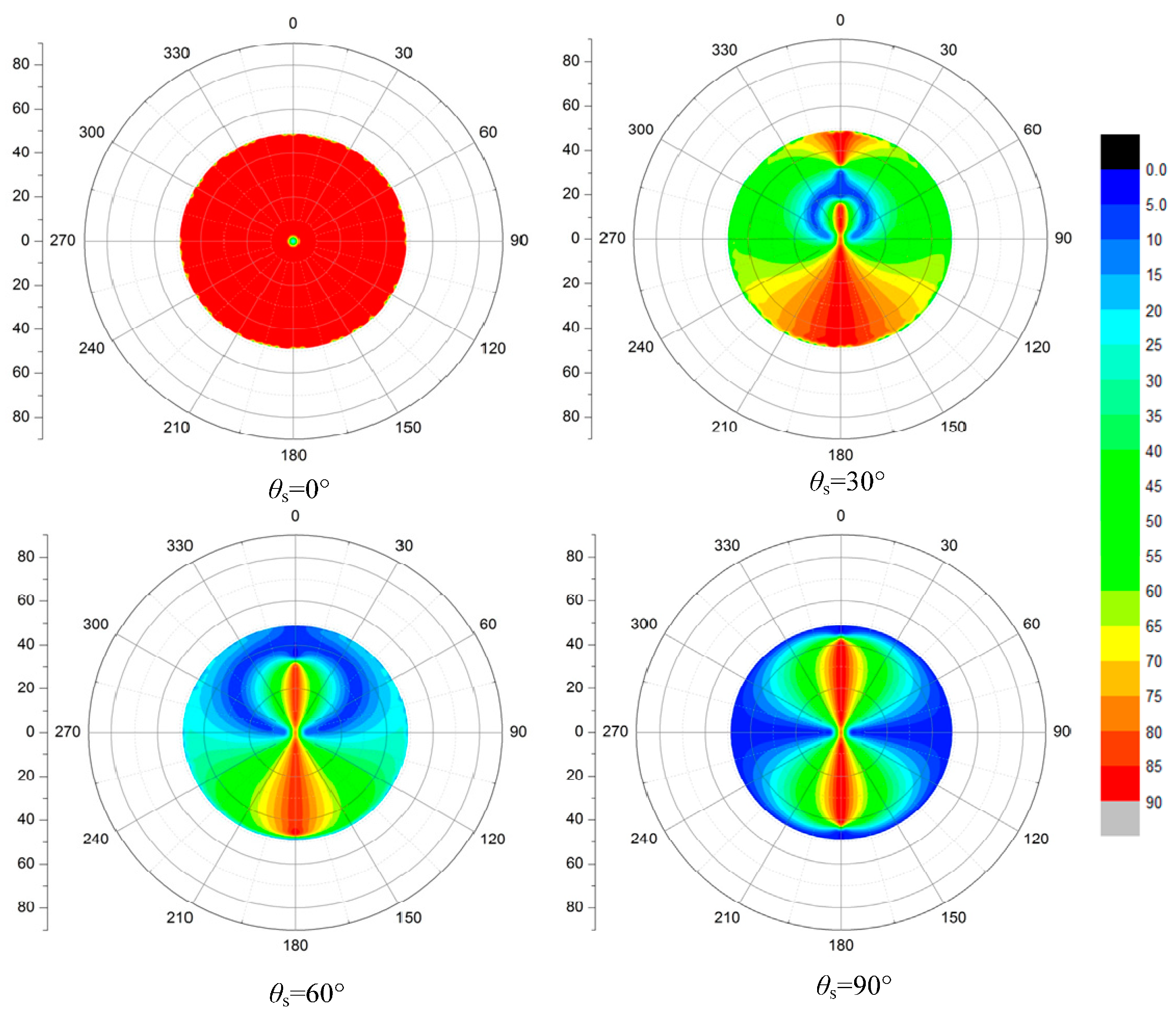
When exploring the transmission light polarization, we start with the polarization and transmission patterns of skylight transmitted through a calm water surface. In this case, the transmission Mueller matrix is related to incident direction only, and the direct solar light has no effect on the polarization distribution of the underwater light field because of their unified incident direction. Thus, we only consider the incident skylight when the surface is flat. The entire celestial hemisphere condensed into Snell’s window with an angular extent of 97°. Outside the Snell’s window, the light from deeper layers is totally reflected and it is dim (under the condition that the substrates are not bright and the scattering constituents of water are normal). Two-dimensional patterns of degree and direction of polarization of refracted skylight are presented for various zenith angles of the sun. The three-dimensional celestial hemisphere (Figure 4) is represented in two dimensions in a polar-coordinate system. The zenith angle and azimuth angle from the solar meridian are measured radially and tangentially. The zenith is at the origin and the horizon corresponds to the outermost circle in this two-dimensional coordinate system.
As shown in Figure 4, the boundary of Snell’s window is sharp when the water surface is calm [7]. There is a strong contrast between the bright scene above and the darker reflections from deep water. The polarization patterns are limited within the Snell’s window. The pattern of DOP is concentric around the sun position, making it symmetrical about the solar principal plane [22,28]. When the sun is at the zenith, the maximum DOP of transmitted light spreads over the edge of Snell’s window. With the increasing of SZA, the DOP of refracted light increases on the whole. When SZA approaches 90°, there is a band of maximum DOP located in the vertical direction of the sun’s meridian. The max DOP of about 70% occurs at sunrise and sunset near the underwater surface. However, according to the Fresnel law as shown in Figure 2, the maximum refraction light is only 28% for the unpolarized sunlight incident at the horizon. The polarization state of incident skylight significantly enhances the DOP of downwelling refracted light. Thus, the polarization state of skylight plays a very important role in determining the DOP of downwelling refracted light.
As shown in Figure 5, when the sun reaches the zenith, all the incident light E-vectors are horizontal and remain in a horizontal direction after being refracted by a calm surface except for the incident beam in the zenith direction. This is because the attenuation of parallel E-vector component is lower than that of vertical E-vector component and this difference has a lower effect on the incident light polarization. Thus, most of transmitted light is horizontal, only the AOP of incident light near the sun changes after refraction due to the very low DOP. For the same reason, there are two split singular points near the apparent sun position in the AOP pattern of refracted light [7]. In addition, in addition to the normal incidence, the main vibration direction of refracted light is not horizontal for any other angles of incidence, but is parallel to the scattering plane for all incident angles, so that the AOP changes with the movement of the sun position [50].
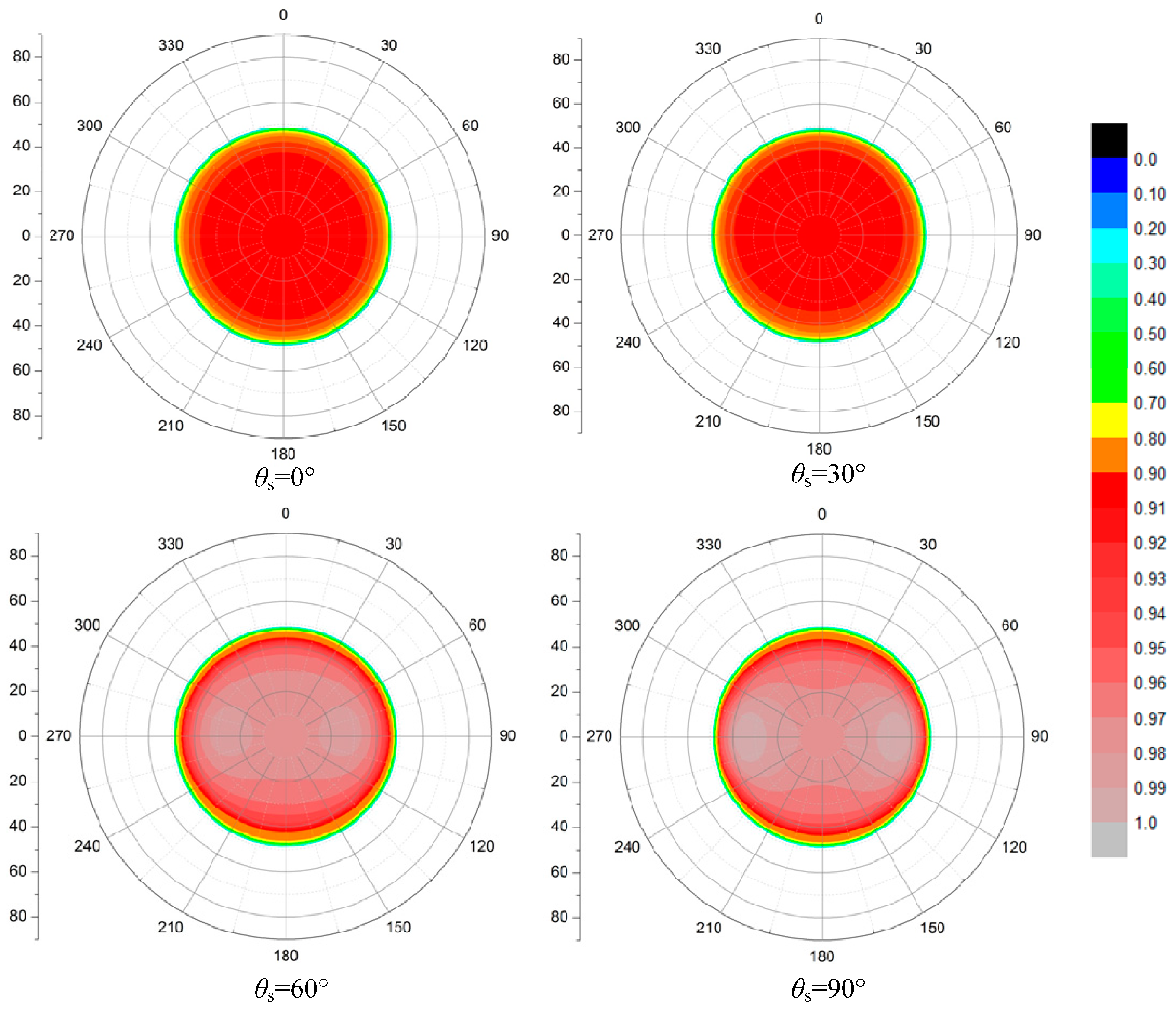
The distributions of transmitted light under the calm surface at different SZAs are shown in Figure 6. We notice that most energy of incident light can pass through the water surface, so the transmitted intensity varies from 0.9 to 1 as a whole, and rises even further with the increasing of SZA. When the SZA is larger (such as 90°) and enhances the resolution of the color bar, we can find a strip of high intensity close to 1 in the direction perpendicular to the sun’s meridian with two bright spots emerging near the Brewster angle. This complies with the two excessively bright areas when observing the whole sky underwater. This is primarily due to the vertical polarized incident skylight with high DOP in that direction when the sun is on the horizon, so the low reflectance leads to the high transmittance. Moreover, the reflectance of incident light near the Brewster angle is lower, so that there are two bright spots [7]. In addition, when light passes through the air–water surface, the n2 law for radiance is applicable and shown as below [4,51].
where n1 is the refractive index for first medium and n2 is the refractive index for the second medium. L1 is the radiance in the first medium and L2 is the radiance in the second medium.
We can know that the intensity of transmitted light under water is 1.78 times stronger than that of the incident light. Due to the smaller field of view, the radiation intensity within the unit field increases according to the law of energy conservation. In conclusion, the transmitted intensity in the Snell’s window is generally high.
3.2. Polarization and Transmittance Patterns of Full Incident Light Passed through a Wavy Water Surface
Undoubtedly, wavy surfaces affect the underwater light field and not only changes the intensity distribution, but also change the polarization patterns, especially in shallow depth water observations. This is mainly induced by the change of the height field of the wave surface and the wave focusing caused by the variation of the real incident angle [52]. The polarization pattern spreads out of the Snell’s window owing to the wave surface. Thus, there are two different underwater polarization patterns, one inside and the other outside Snell’s window [7].
The polarization and transmission patterns of transmitted light under a wavy water surface at different SZAs are presented in this section, and the effects of various wind speed and incident light sources on the patterns are analyzed.
3.2.1. The Polarization Patterns of Transmitted Light under a Wavy Water Surface
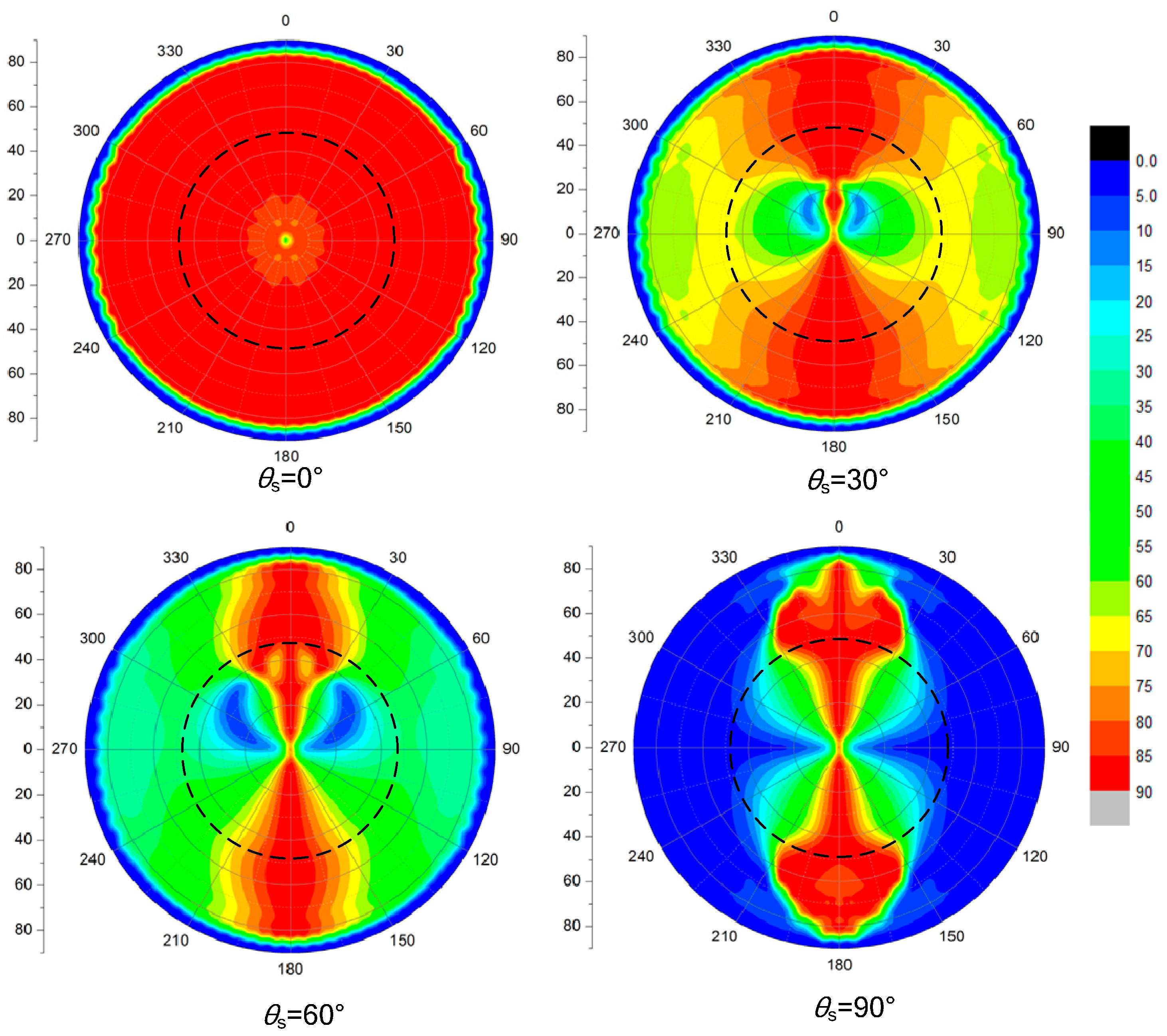
Unlike the calm surface conditions, which only consider the skylight incidence, we consider the whole celestial light, which includes both the contributions of the direct solar light and diffused skylight, to simulate the polarization patterns of transmitted light under a wavy water surface. Just like the calm water, the polarization pattern under wavy water, including DOP and AOP, is symmetrical about the solar meridian plane (see Figure 7 and Figure 8). The ever-changing position of the sun in the sky exerts a major influence on the pattern of polarization underwater. The DOP and AOP patterns under various SZAs are shown in Figure 7 and Figure 8, where the wind speed is 5 m/s, wind direction is 0°. Unlike the calm water, there is no sharp border at the margins of Snell’s window which coincides with the measurement by Cronin [28]. The results indicate that the celestial polarization pattern is present within Snell’s window, but it is modified due to refraction and repolarization of skylight at the air–water interface. Horvath called the polarization pattern outside Snell’s window a bulk transmission-polarization pattern which is created by interaction between water and transmitted light [7]. Both of the inside pattern and outside patterns vary obviously with the sun position under a wavy water surface. Similar to the patterns under a flat surface (Figure 4), when the sun is at the zenith, the maximum DOP also distributes on the edge of the Snell’s window. Additionally, the area of maximum DOP lies in the refracted direction normal to the sun’s meridian when the sun is located in any other position. We can also find that the variation of polarization patterns of the underwater light field is obvious owing to the waves, which not only make the patterns non-homogeneous, but also distort them along the direction of wind. When the sun was near the zenith, the electric vector of the polarized light was horizontal and the same at all azimuths, which coincides with the measurement by Waterman [5]. Likewise, the maximum AOP distributes along the sun’s meridian with the singular points emerging (Figure 8), which are not clear except the point on the zenith due to wave fluctuations. Using the statistical probability of the wave slope distribution model to describe the wave surface, the values of distribution patterns in this paper are weighted averages, not instantaneous results, which are comparable to the measurements. Therefore, the patterns will appear outside the Snell’s window and continue with the patterns inside the window.
3.2.2. The Transmittance Distribution of Transmitted Light under a Wavy Water Surface
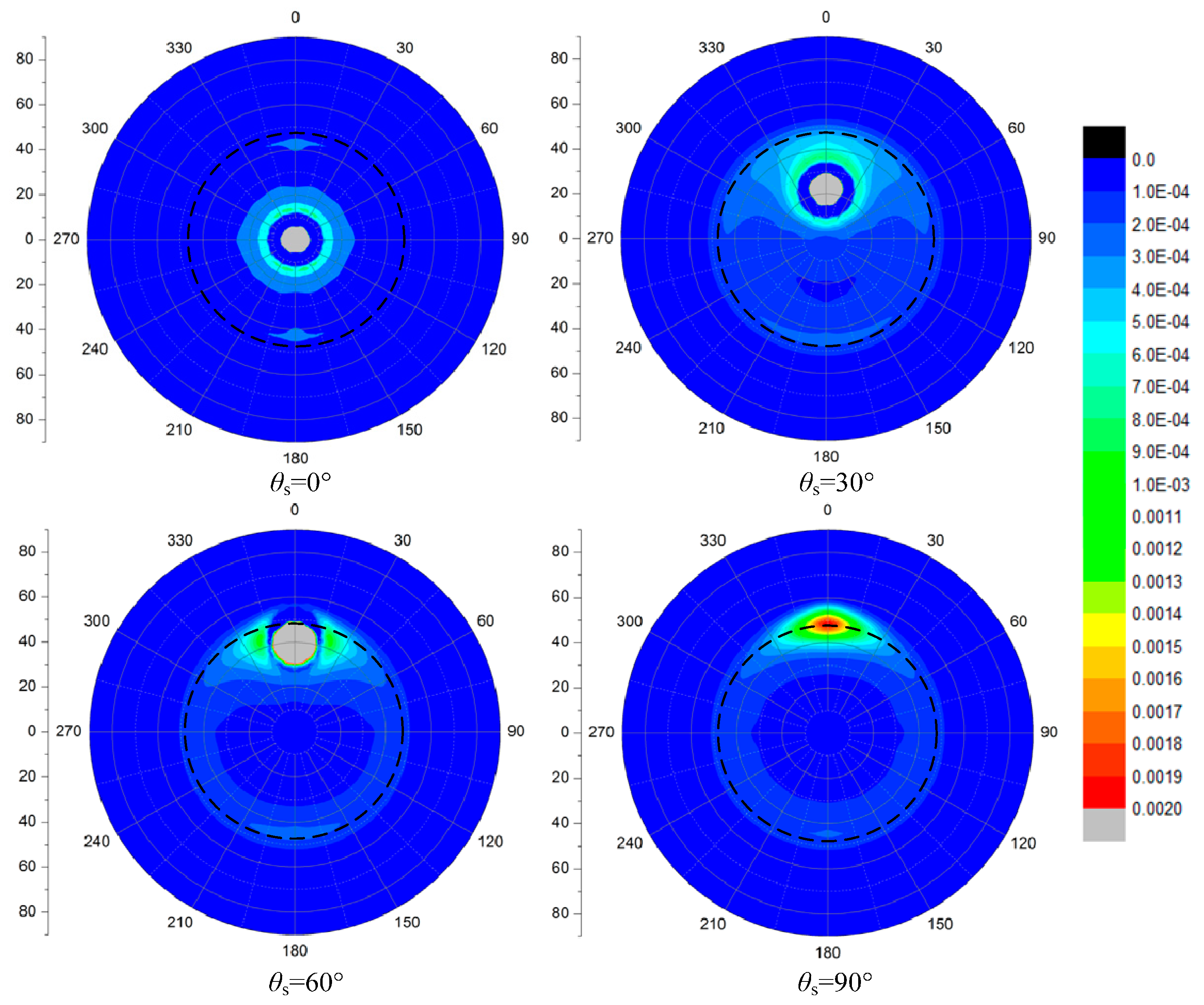
In addition to its degree of polarization and direction of polarization, the intensity of downwelling transmitted light was discovered to also vary systematically with the relative position of the sun and the points observed underwater. Figure 9 illustrates the relative intensity distribution of transmitted light under a wavy water surface under different SZAs. We can see that the intensity distributions focus in the Snell’s window, which demonstrates that the Snell’s window is the real passageway to form the underwater light field. The direct solar incidence leads to the maximum intensity region near the apparent sun position under water, and there will appear a bright ring on the edge of the window with a greater solar zenith angle. In addition, when the sun is available, the maximum intensity region is where the brightness expands as the SZA increases.
3.2.3. The Effects of Other Factors on Transmitted Light Polarization Patterns
(1) The effect of wave fluctuation
Waves are formed when wind velocity increases; the stronger the wind, the higher the waves. They are called wind-waves. When the wind velocity decreases, there are still waves on the sea for a considerable time, but the length of the waves grows larger and larger. They are so called swell. The swell may have a direction different from that of the wind, which may again rise from another direction and create new wind-waves [22]. In this study, we only take the wind-waves into account and omit the gravity wave for the sake of adoption of the Cox–Munk wave model.
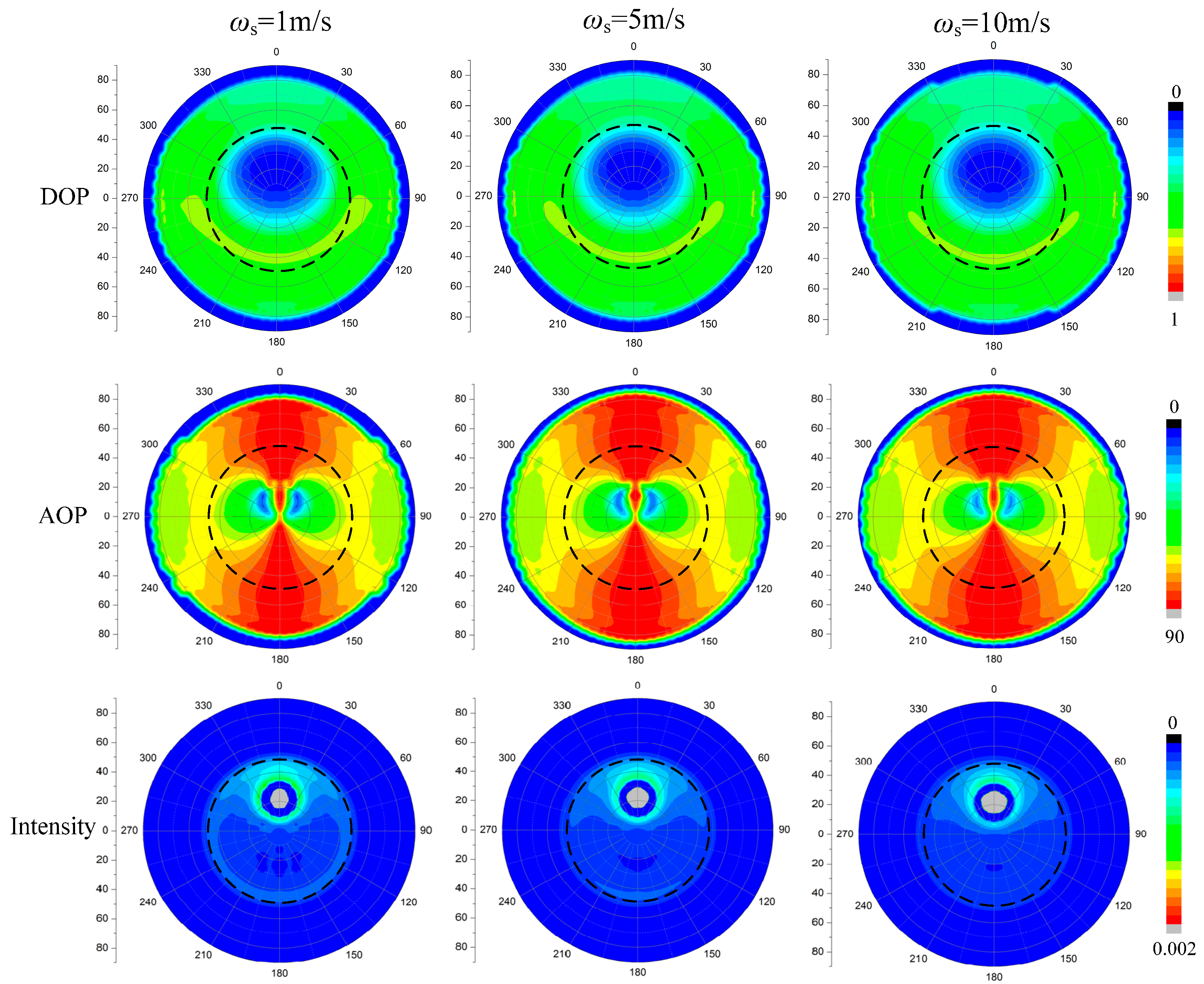
Figure 10 shows the effect of wind speed on the DOP, AOP and intensity patterns of transmitted light under water. We can find that the influence of wind speed (e.g., 1, 5, and 10 m/s) on the patterns of DOP is obvious. The DOP patterns spread slightly to the direction of the wind and the maximum DOP band narrows with the increasing wind speed. The polarization under water also decreases when the surface of the water is undulating, as the sunlight can be refracted in many directions by the waves. Then, there are no more parallel sunbeams underwater, hence there is diminishing polarization of scattered light under the surface. Just as shown in the first row in Figure 10, the DOP decline with the wind speed increasing, as the direct underwater light tends to diffuse due to the wave fluctuation. When the water surface is undulating, the sunlight can be refracted in many directions by the waves. Then, there are no more parallel sunbeams underwater, hence the diminishing polarization of scattered light under the surface. The pattern of AOP is also symmetrical to the sun’s meridian plane just that of AOP. Compared with DOP, however, the AOP patterns are more stable. All these could provide stable orientation information sources for polarization sensing aquatic animals for navigation. However, the effect of wind speed on the intensity distribution under water is significant: the bright ring appears on the edge at low wind speed, but disappears with the increasing wind speed, and the bright circle near the apparent sun position expands. In addition, the edge of the Snell’s window becomes unclear.
(2) The effect of different incident sources
The refracted polarization patterns of wave water surface depend not only on the presence or absence of waves but also to a high degree upon illumination [22]. In this study, the source of the incident light can be conceived as being from a direct light source (sunlight) or diffuse light source (skylight or scattered light). The former is partially polarized and latter is unpolarized. Unpolarized sunlight becomes slightly partially linear polarized as it refracts through the water surface, but the primary production of the significant linear polarization is caused by the skylight. Figure 11 indicates that the direct solar incident light only contributes to the polarization and intensity patterns at the apparent sun position under water, while the scattering incident skylight dominates the polarization patterns of the underwater light field. As mentioned above, the maximum DOP of transmission is no more than 0.28 according to the Fresnel’s equations. However, the DOP of transmission can exceed 0.6. Therefore, it is obvious that the refracted polarization information underwater mainly come from the skylight rather than from the refraction process. From the three AOP patterns, we can find that the direct light may promote the formation of the singular points except the point on the zenith. In addition, the direct light leads to the brightest part of the transmitted light field under water, and the scattering skylight slightly affects the whole intensity distribution instead. Thus, the direct solar light is the dominant source of the brightness of the underwater light field.
3.3. Polarization and Transmittance Patterns of Full Incident Light Passed through a Wavy Water Surface
When a beam transfers into the water surface, both reflection and refraction occur. The two processes not only change the intensity, but also the polarization of incident light. This section demonstrates the polarization patterns of the skylight, reflected light and refracted light under various SZAs (30°, 60° and 90°) and then analyzes the differences between the polarization and intensity patterns of reflection and refraction and the relationships between them.
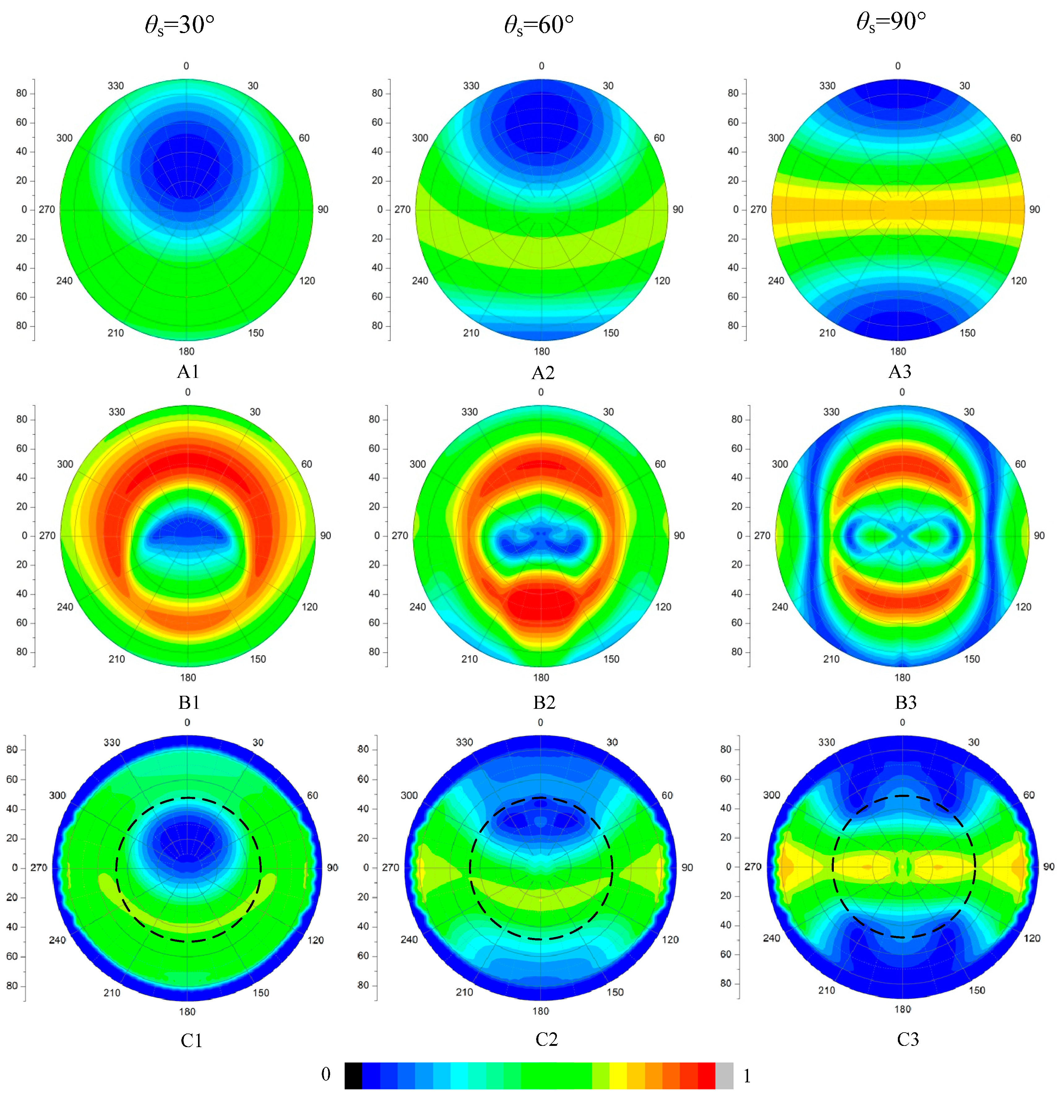
The DOP patterns of skylight at different SZAs are shown in Figure 12. According to the semi-empirical Rayleigh scattering model, the DOP of scattering light under clear skies is directly related to the scattering angle. As the SZA increases, the maximum DOP region whose scattering angle is 90° moves to the zenith where the SZA is 90°. While the DOP of the skylight near the sun is the lowest. That is to say, the further from the sun, the stronger is the DOP, during the sunrise and sunset. Underwater, the apparent sun looks like the sun in the sky, though the wave distorts the DOP patterns, the patterns are still similar to the patterns of the skylight (Figure 12A,C). As shown in Figure 12B,C, with the increasing of SZA, the DOP of reflected light decreases while that of transmitted light rises as a whole. The maximum DOP of reflected light is always distributed near the Brewster angle, and that of transmitted light lies in the refracted direction instead.
In Figure 13A, we can see that the singular spots of the AOP patterns of skylight are always at the zenith and the sun position no matter where the sun is. The light from the sun’s meridian is always horizontal polarized. The AOP patterns of transmitted light under water resemble that of incident skylight from Figure 13A,C. This is likely that E-vector of the light does not change its phase when refracted by water surface. However, when light transfers from an optically thinner medium to a denser medium, the reflected light comes up with a phase change of π based on the Fresnel’ law. Thus, the reflection changes not only the intensity, but also the phase of incident light, and then the polarization patterns of reflected light are entirely different from that of skylight, as shown in Figure 12B and Figure 13B. We can conclude the polarization characteristics of incident light are reserved in the Snell’s window under water when refraction occurs, especially under calm surface conditions.
The pattern of downwelling polarized light under the wavy water surface is superimposed by the pattern of skylight polarization and that alter by refraction and the disturbance of the wave movement.
4. Discussion
Waterman first measured underwater polarization; subsequently, there are many measurements of linear-polarized light transmitted into water surface [28,31,52,53,54,55,56,57].
To evaluate above simulation results, we have made a comparison with the data measured by Bhandari and his colleagues in 2009 at the R/P Flip, off Hawaii [24]. The results are shown in Figure 14, Figure 15 and Figure 16. The measurements are carried out at one meter below the water surface and the water is clear. In that case the scattering effects in water can be omitted. The wind speed is 6 m/s.
The data in Figure 14A were collected at 520 nm in very clear water on 7 September 2009. The data in Figure 14B are the simulated data. In Figure 14, we can find that the majority of downwelling radiance is limited in the Snell’s cone. Part of the radiance exceeds the edge of Snell’s cone due to the fluctuation of the water surface. The simulated data correspond well with the measured data, not only in the major distribution but also in some details. For example, the radiance in the central part of the Snell’s cone is lower than the surrounding circle. The direct solar disk is extended at the edge of Snell’s cone. There are also some differences especially at the edge of Snell’s cone. The main reason is that our calculation uses the Cox–Munk model, which gives the average results of the transmittance at a certain angle. However, the photos taken by Bhandari reveal the real state of water surface.
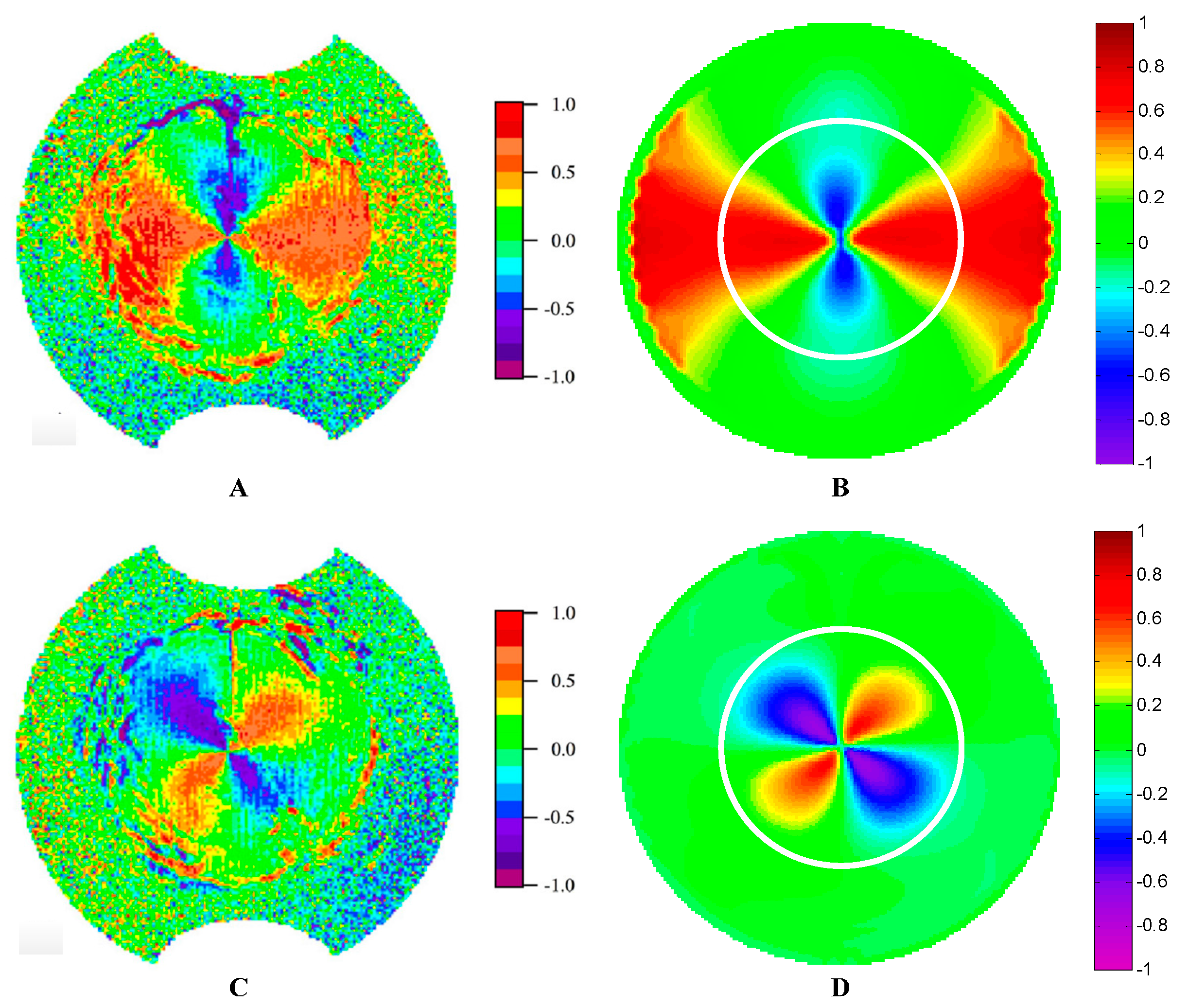
Figure 15 shows the comparison between the measured data and our simulation data on Q/I and U/I. In the Snell’s cone, the shapes of the two sets of graphs agree well with each other. The correctness of our calculation model is proven in a way. The main differences appear on the edge and outside of the Snell’s cone. The graphs near the edge seem to be disordered for the measured data which are probably due to the fluctuation of the water surface. Another reason comes from the measurement error, since the Stokes parameters of downwelling radiance were measured with four lenses. As for the outside circle of the Snell’s cone, it is noisy, because the energy of radiance is too low at this part. The simulated data cannot reveal the fluctuation effects and will not be influenced by the low radiance.
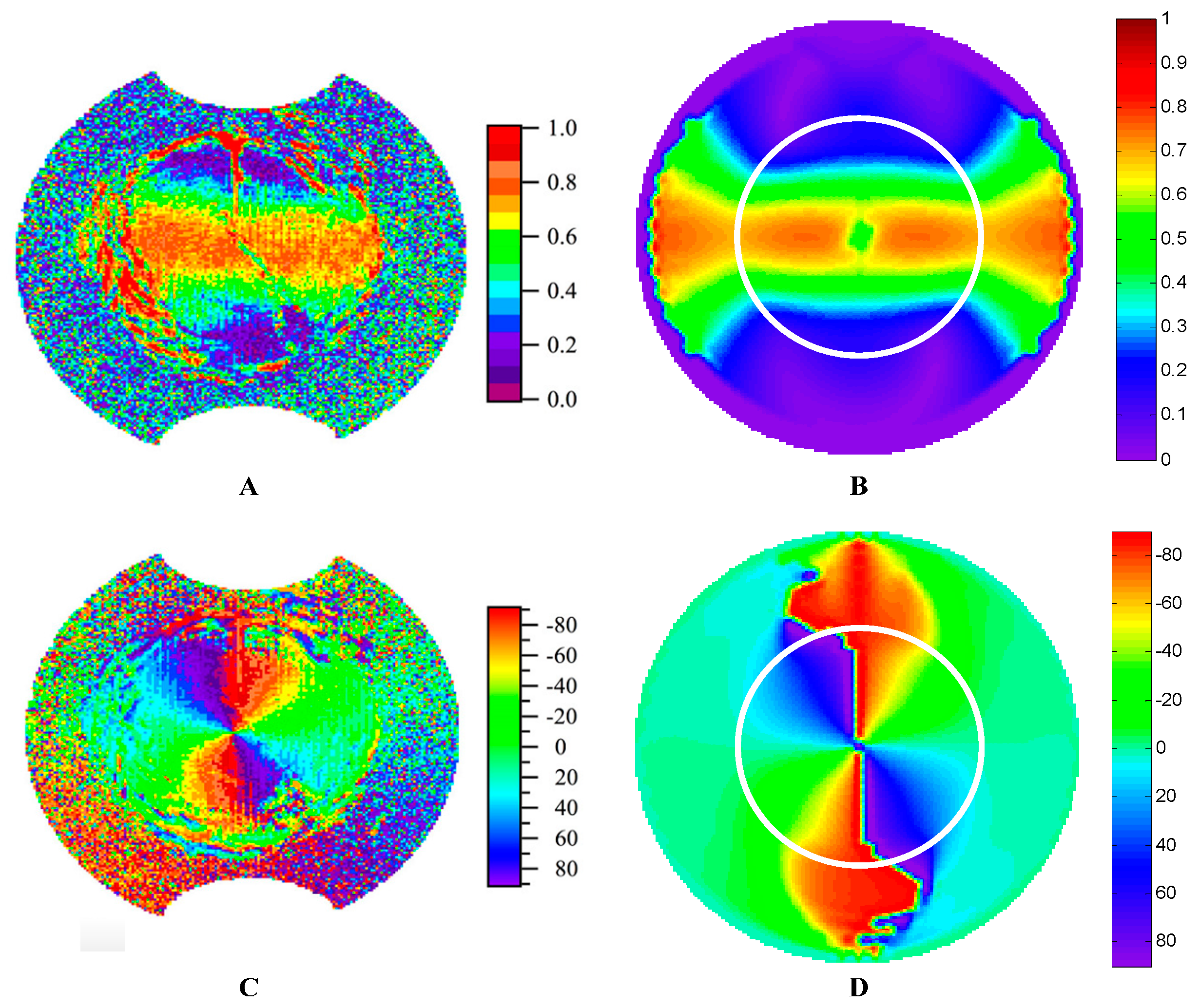
It is obvious that the features of DOP and AOP are similar between the measured data and our simulated results. The differences also appear on the edge and outside circle of the Snell’s cone. The reason has been explained in the former paragraph. In the Snell’s cone, the DOP and AOP patterns are mainly decided by the skylight polarization patterns. The comparison between the measured data and our simulated results shows great similarity, which proves the correctness of our model. The influence of fluctuated water surface mainly appears at the edge of the Snell’s cone. The noise outside the Snell’s cone comes from the low radiance energy of the downwelling light. Of course, both of the measured data and the simulated results are collected under the situation of shallow depth and clear water.
The research on the polarization characteristics of transmitted light under natural water is an important subject in polarization vision field. However, the polarization pattern of the underwater light field is very complex, it is not only influenced by the sun position, wave fluctuation and incident sources, but also the factors of water depth, turbidity caused by suspended particulates and multiple scattering in the water. The model described in this paper worked well and provides relatively satisfactory results, however there are some points we should emphasize here.
In this paper, we focus on the light transmitted downward passing through the wave water surface. The effect of waves and the incident skylight on the polarization pattern of downward light in shallow depth water are emphasized. The contribution of scattering in water and reflection at the water bottom to the polarization of the underwater light field was not considered in this study. Therefore, this model may not validate the situation of upward light or deepwater environments (deeper than about 0.5 m) where the multiple scattering dominates the underwater light field. At great depths (many tens of meters), the illumination is dominated by diffuse light caused by the submarine particle scattering. The polarization is further weakened by the underwater scattering [53]. Moreover, in optical shallow waters, bottom reflection will affect the polarization patterns [23].
Besides linearly polarized light, circularly polarized light can also occur under water. The latter is formed indirectly by total reflection of the existing underwater linear polarized light against the lower side of the water surface [5,22]. We focus on the downwelling refraction of celestial light rather than involve the upwelling refraction or the total refraction process in this study. Thus, the circularly polarized light was also neglected.
We omitted the spectral character of skylight and underwater since the refractive indices of air and water vary slightly with the wavelength of light. Furthermore, according to the field measurements [23,28], the polarization in water is relatively insensitive to wavelength. Patterns of both the overall e-vector orientation and degree of polarization are similar from 360 to 550 nm.
The polarization pattern of skylight is very complex which is influenced by many factors. These include the position of the sun, the coverage of the cloud, the earth’s albedo, atmospheric turbidity, multiple scattering and depolarization owing to anisotropy of air molecules. The semi-empirical skylight polarization model adopted in this study is shown to be effective to describe the polarization pattern of the skylight. However, the semi-empirical parameter is difficult to parameterize such factors. Precision modeling can resort to the vector transfer model such as 6SV, RT3, etc. However, coupling such a model needs much more computation time. Furthermore, both of these vector radiative transfer models did not take cloud cover into account. All of these factors above need to be taken into consideration in future research.
5. Conclusions
This work may be briefly summarized as follows. In this paper, we present a model to describe the polarization patterns of celestial light when refracted by the wavy water surface. The polarization characteristics and the radiance distribution pattern of the skylight are both taken into consideration. The polarization patterns and intensity distribution of refracted light off wave water surface were calculated. The model was validated by the underwater experimental measurements. The experimental and theoretical values agree well qualitatively. This work could provide a quantitative description of the repolarization and transmittance of celestial light transmitted through the wave water surface.
The dependence of the submarine light field polarization on the illumination and surface wave conditions, solar zenith and azimuth angles, and the viewing angles are discussed in detail. The polarization properties of transmitted celestial light under shallow depth water are mainly dependent on the incident polarized skylight.
Though the wave surface distorts the polarization patterns under water and leads them to exist out of the Snell’s window, the polarization patterns within the Snell’s window are similar to that of the skylight. Wind speed slightly affects the underwater polarization distribution, which expands a little along the wind direction as the wind speed rises. The direct solar light dominants the intensity distribution in the light field under water, while the scattering light from the sky is the dominant effect on determining the polarization patterns of transmitted light. We can conclude that the refraction slightly influences the polarization characteristic of incident light, in addition to the stable polarization field under water, which are beneficial to aquatic animals that orientate themselves with polarized sensing.
Comparing the polarization patterns of reflected light to that of transmitted light, we can find that reflection process significantly change the original polarization patterns of incident light, while the patterns of refraction have the basic characteristics of that of the incident light. The maximum DOP of reflected light is always distributed near the Brewster angle, and that of transmitted light lies in the refracted direction of Brewster angle instead.
Underwater polarization has drawn great attention to many fascinating areas of research yet to be explored. Combination of achievement in radiative transfer simulation and novel developed detector technology and data inversion algorithms will certainly provide many new and exciting research topics in ocean optics and ocean color remote sensing [3,14].
Acknowledgments
We are grateful to Chunyue Niu and Victoria Cheung for their constructive help and suggestions. We are also grateful to the anonymous reviewers for their valuable comments and suggestions. This work was supported by the flowing funds: National Natural Science Foundation of China (Grant No. 40901168); Beijing Natural Science Foundation (Grant No. 8162028); Open Fund of Key Laboratory of Space Ocean Remote Sensing and Application (Grant No.201602021); Open Fund of State Key Laboratory of Remote Sensing Science (Grant No. OFSLRSS201506); National Program on Key Basic Research Project (Grant No. 2014CB744204); and Research on data processing theory and methods of the auxiliary lines selection based on satellite remote sensing image (Grant No. GCB17201600036).
Author Contributions
Guanhua Zhou and Wujian Xu conceive the model and wrote the paper. Jiwen Wang and Kai Zhang carried out the calculation and analyzed the data. Zhongqi Ma made the validation and analysis.
Conflicts of Interest
The authors declare no conflict of interest. The founding sponsors had no role in the design of the study; in the collection, analyses, or interpretation of data; in the writing of the manuscript, and in the decision to publish the results.
References
- Amir, I.; Alexander, G.; Tristan, H.; Alberto, T.; Jacek, C.; Samir, A. The relationship between upwelling underwater polarization and attenuation/absorption ratio. Opt. Express 2012, 20, 25662–25680. [Google Scholar]
- Alberto, T.; Alex, G.; Tristan, H.; Amir, I.; Jacek, C.; Barry, G.; Fred, M.; Sam, A. Estimating particle composition and size distribution from polarized water-leaving radiance. Appl. Opt. 2011, 50, 5047–5058. [Google Scholar]
- Kattawar, G.W. Genesis and evolution of polarization of light in the ocean. Appl. Opt. 2013, 52, 940–948. [Google Scholar] [CrossRef] [PubMed]
- Mobley, C.D. Light and Water: Radiative Transfer in Natural Waters; Academic Press: San Diego, CA, USA, 1994. [Google Scholar]
- Waterman, T.H. Polarization patterns in submarine illumination. Science 1954, 120, 927–932. [Google Scholar] [CrossRef] [PubMed]
- Horváth, G.; Varjú, D. Polarized Light in Animal Vision: Polarization Patterns in Nature; Springer: Heidelberg, Germany, 2004. [Google Scholar]
- Horváth, G.; Varjú, D. Underwater refraction–polarization patterns of skylight perceived by aquatic animals through Snell’s window of the flat water surface. Vis. Res. 1995, 35, 1651–1666. [Google Scholar] [CrossRef]
- Harmel, T.; Chami, M. Invariance of polarized reflectance measured at the top of atmosphere by PARASOL satellite instrument in the visible range with marine constituents in open ocean waters. Opt. Express 2008, 16, 6064–6080. [Google Scholar] [CrossRef] [PubMed]
- Tonizzo, E.; Gilerson, A.; Harmel, T.; Ibrahim, A.; Chowdhary, J.; Gross, B.; Moshary, F.; Ahmed, S. Estimating particle composition and size distribution from polarized water-leaving radiance. Appl. Opt. 2011, 50, 5047–5058. [Google Scholar]
- Harmel, T.; Alexander, G.; Alberto, T.; Jacek, C.; Alan, W.; Robert, A.; Sam, A. Polarization impacts on the water-leaving radiance retrieval from above-water radiometric measurements. Appl. Opt. 2012, 51, 8324–8340. [Google Scholar] [CrossRef] [PubMed]
- Chowdhary, J.; Cairns, B.; Waquet, F.; Knobelspiesse, K.; Ottaviani, M.; Redemann, J.; Travis, L.; Mishchenko, M. Sensitivity of multiangle, multispectral polarimetric remote sensing over open oceans to water-leaving radiance: Analyses of RSP data acquired during the MILAGRO campaign. Remote Sens. Environ. 2012, 118, 284–308. [Google Scholar] [CrossRef]
- Ibrahim, A.; Gilerson, A.; Harmel, T.; Tonizzo, A.; Chowdhary, J.; Ahmed, S. The relationship between upwelling underwater polarization and attenuation/absorption ratio. Opt. Express 2012, 20, 25662–25680. [Google Scholar] [CrossRef] [PubMed]
- Kattawar, G.W.; Yang, P.; You, Y.; Bi, L.; Xie, Y.; Huang, X.; Hioki, S. Polarization of light in the atmosphere and ocean. In Light Scattering Reviews 10 Light Scattering and Radiative Transfer; Kokhanovsky, A.A., Ed.; Springer: Heidelberg, Germany, 2016; pp. 3–40. [Google Scholar]
- Harmel, T. Recent developments in the use of light polarization for marine environment monitoring from space. In Light Scattering Reviews; Kokhanovsky, A.A., Ed.; Springer: Heidelberg, Germany, 2016; Volume 10, pp. 41–84. [Google Scholar]
- Gilerson, A.; Zhou, J.; Oo, M.; Chowdhary, J.; Gross, B.M.; Moshary, F.; Ahmed, S.A. Retrieval of chlorophyll fluorescence from reflectance spectra through polarization discrimination: Modeling and experiments. Appl. Opt. 2006, 45, 5568–5581. [Google Scholar] [CrossRef] [PubMed]
- Frisch, K.V. Die Polarisation des Himmelslichtes als orientierender Faktor bei den Tanzen der Bienen. Cell. Mol. Life Sci. 1949, 5, 142–148. [Google Scholar] [CrossRef]
- Wehner, R. Polarization vision—A uniform sensory capacity. J. Exp. Biol. 2001, 204, 2589–2596. [Google Scholar] [PubMed]
- Brines, M.L.; Gould, J.L. Skylight polarization patterns and animal orientation. J. Exp. Biol. 1982, 96, 69–91. [Google Scholar]
- Horváth, G.; Varjú, D. Reflection–polarization patterns at flat water surfaces and their relevance for insect polarization vision. J. Theor. Biol. 1995, 175, 27–37. [Google Scholar] [CrossRef] [PubMed]
- Waterman, T.H. Polarization of marine light fields and animal orientation. Proc. SPIE 1988, 0925, 431–437. [Google Scholar]
- Zhou, G.; Xu, W.; Niu, C.; Zhao, H. The polarization patterns of skylight reflected off wave water surface. Opt. Express 2013, 21, 32549–32565. [Google Scholar] [CrossRef] [PubMed]
- Können, G.P. Polarized Light in Nature; Cambridge University Press: New York, NY, USA, 1985. [Google Scholar]
- Ivanoff, A.; Waterman, T.H. Factors, mainly depth and wavelength, affecting the degree of underwater light polarization. J. Mar. Res. 1958, 16, 283–307. [Google Scholar]
- Voss, K.J.; Gleason, A.C.R.; Gordon, H.R.; Kattawar, G.W.; You, Y. Observation of non-principal plane neutral points in the in-water upwelling polarized light field. Opt. Express 2011, 19, 5942–5952. [Google Scholar] [CrossRef] [PubMed]
- Voss, K.J.; Fry, E.S. Measurement of the Mueller matrix for ocean water. Appl. Opt. 1984, 23, 4427–4439. [Google Scholar] [CrossRef] [PubMed]
- Bhandari, P.; Voss, K.J.; Logan, L. An instrument to measure the downwelling polarized radiance distribution in the ocean. Opt. Express 2011, 19, 17609–17620. [Google Scholar] [CrossRef] [PubMed]
- You, Y.; Kattawar, G.W.; Voss, K.J.; Bhandari, P.; Wei, J.; Lewis, M.; Zappa, C.J.; Schultz, H. Polarized light field under dynamic ocean surfaces: Numerical modeling compared with measurements. J. Geophys. Res. 2011, 116, 1978–2012. [Google Scholar] [CrossRef]
- Cronin, T.W.; Shashar, N. The linearly polarized light field in clear, tropical marine waters-spatial and temporal variation of light intensity, degree of polarization and e-vector angle. J. Exp. Biol. 2001, 204, 2461–2467. [Google Scholar] [PubMed]
- Kattawar, G.W.; Adams, C.N. Stokes vector calculations of the submarine light field in an atmosphere–ocean with scattering according to a Rayleigh phase matrix: Effect of interface refractive index on radiance and polarization. Limnol. Oceanogr. 1989, 34, 1453–1472. [Google Scholar] [CrossRef]
- Sabbah, S.; Lerner, A.; Erlick, C.; Shashar, N. Under water polarization vision-a physical examination. Recent Res. Dev. Exp. Theor. Biol. 2005, 1, 123–176. [Google Scholar]
- Sabbah, S.; Barta, A.; Gál, J.; Horváth, G.; Shashar, N. Experimental and theoretical study of skylight polarization transmitted through Snell’s window of a flat water surface. J. Opt. Soc. Am. A 2006, 23, 1978–1988. [Google Scholar]
- Mishchenko, M.I.; Travis, L.D. Satellite retrieval of aerosol properties over the ocean using polarization as well as intensity of reflected sunlight. J. Geophys. Res. 1997, 102. [Google Scholar] [CrossRef]
- Zhai, P.; Hu, Y.; Chowdhary, J.; Trepte, C.R.; Lucker, P.L.; Josset, D.B. A vector radiative transfer model for coupled atmosphere and ocean systems with a rough interface. J. Quant. Spectrosc. Radiat. 2010, 111, 1025–1040. [Google Scholar] [CrossRef]
- Xu, Z.; Yue, D.K.P.; Shen, L.; Voss, K.J. Patterns and statistics of in-water polarization under conditions of linear and nonlinear ocean surface waves. J. Geophys. Res. 2011, 116, 1978–2012. [Google Scholar] [CrossRef]
- Mobley, C.D. Polarized reflectance and transmittance properties of windblown sea surfaces. Appl. Opt. 2015, 54, 4828–4849. [Google Scholar] [CrossRef] [PubMed]
- Hieronymi, M. Polarized reflectance and transmittance distribution functions of the ocean surface. Opt. Express 2016, 24, A1045–A1068. [Google Scholar] [PubMed]
- Chami, M.; Lafrance, B.; Fougnie, B.; Chowdhary, J.; Harmel, T.; Waquet, F. OSOAA: A vector radiative transfer model of coupled atmosphere–ocean system for a rough sea surface application to the estimates of the directional variations of the water leaving reflectance to better process multi-angular satellite sensors data over the ocean. Opt. Express 2015, 23, 27829–27852. [Google Scholar] [PubMed]
- Foster, R.; Gilerson, A. Polarized transfer functions of the ocean surface for above-surface determination of the vector submarine light field. Appl. Opt. 2016, 55, 9476–9494. [Google Scholar] [CrossRef] [PubMed]
- Dickey, T.D.; Kattawar, G.W.; Voss, K.J. Shedding new ligdht on light in the ocean. Phys. Today 2011, 64, 44–49. [Google Scholar] [CrossRef]
- Voss, K.J.; Souaidia, N. POLRADS: Polarization radiance distribution measurement system. Opt. Express 2010, 18, 19672–19680. [Google Scholar] [CrossRef] [PubMed]
- Guenther, R.D. Modern Optics; Wiley: New York, NY, USA, 1990. [Google Scholar]
- Harrison, A.W.; Coombes, C.A. Angular distribution of clear sky short wavelength radiance. Sol. Energy 1988, 40, 57–63. [Google Scholar] [CrossRef]
- Coulson, K.L. Polarization and Intensity of Light in the Atmosphere; A. Deepak Publishing: Hampton, VA, USA, 1988. [Google Scholar]
- Lynch, D.K. Snell’s window in wavy water. Appl. Opt. 2015, 54, B8–B11. [Google Scholar] [CrossRef] [PubMed]
- Cox, C.; Munk, W. Measurement of the roughness of the sea surface from photographs of the sun’s glitter. J. Opt. Soc. Am. 1954, 44, 838–850. [Google Scholar] [CrossRef]
- Cox, C.; Munk, W. Slopes of the Sea Surface Deduced from Photographs of Sun Glitter; Bulletin of the Scripps Institution of Oceanography of the University of California, La Jolla; University of California Press: Oakland, CA, USA, 1956. [Google Scholar]
- Ebuchi, N.; Kizu, S. Probability distribution of surface wave slope derived using sun glitter images from geostationary meteorological satellite and surface vector winds from scatterometers. J. Oceanogr. 2002, 58, 477–486. [Google Scholar] [CrossRef]
- Saunders, P.M. Shadowing on the Ocean and the existence of the horizon. J. Geophys. Res. 1967, 18, 4643–4649. [Google Scholar] [CrossRef]
- Ottaviani, M.; Spurr, R.; Stamnes, K.; Li, W.; Su, W.; Wiscombe, W. Improving the description of sunglint for accurate prediction of remotely sensed radiances. Quant. Spectr. Radat. Trans. 2008, 109, 2364–2375. [Google Scholar] [CrossRef]
- Waterman, T.H. Reviving a neglected celestial underwater polarization compass for aquatic animals. Biol. Rev. 2006, 81, 111–115. [Google Scholar] [CrossRef] [PubMed]
- Wyatt, C.L. Radiometric calibration: Theory and methods. J. Membr. Biol. 1978, 129, 99–107. [Google Scholar]
- Sabbah, S.; Shashar, N. Underwater light polarization and radiance fluctuations induced by surface waves. Appl. Opt. 2006, 45, 4726–4739. [Google Scholar] [CrossRef] [PubMed]
- Cronin, T.W.; Marshall, J. Patterns and properties of polarized light in air and water. Philos. Trans. R. Soc. B 2011, 366, 619–626. [Google Scholar] [CrossRef] [PubMed]
- Shashar, N.; Sabbah, S.; Cronin, T.W. Transmission of linearly polarized light in seawater-implications for polarization signaling. J. Exp. Biol. 2004, 207, 3619–3628. [Google Scholar] [CrossRef] [PubMed]
- Sabbah, S.; Shashar, N. Light polarization under water near sunrise. J. Opt. Soc. Am. A 2007, 24, 2049–2055. [Google Scholar] [CrossRef]
- Bhandari, P. The Design of a Polarmeter and its Use for the Study of the Variation of Downwelling Polarized Radiance Distribution with Depth in the Ocean. Ph.D. Thesis, University of Miami, Coral Gables, FL, USA, 2011. [Google Scholar]
- Bhandari, P.; Voss, K.J.; Logan, L. The variation of the polarized downwelling radiance distribution with depth in the coastal and clear ocean. J. Geophys. Res. 2011, 116. [Google Scholar] [CrossRef]
Figure 1.
E-vector of an incident beam is reflected and refracted by the interface, Er is the reflected component, Et is the refracted component, and Es and Ep are vertical and parallel component, respectively.
Figure 1.
E-vector of an incident beam is reflected and refracted by the interface, Er is the reflected component, Et is the refracted component, and Es and Ep are vertical and parallel component, respectively.

Figure 2.
(a) The relation curves between reflection coefficients rs, rp, transmission coefficients ts, tp and incident angle θ; and (b) the relation curves between the DOP of reflected and transmitted light and the incident angle.
Figure 2.
(a) The relation curves between reflection coefficients rs, rp, transmission coefficients ts, tp and incident angle θ; and (b) the relation curves between the DOP of reflected and transmitted light and the incident angle.

Figure 3.
(a) Snell’s window for flat water; and (b) the coordinate sketch of the refracted process under the wavy water surface.
Figure 3.
(a) Snell’s window for flat water; and (b) the coordinate sketch of the refracted process under the wavy water surface.

Figure 4.
The DOP (degree of polarization) patterns of skylight transmitted through a calm water surface within the Snell’s window at different solar zenith angle θs = 0°, 30°, 60°, 90°, the DOP ranges from 0 to 1.
Figure 4.
The DOP (degree of polarization) patterns of skylight transmitted through a calm water surface within the Snell’s window at different solar zenith angle θs = 0°, 30°, 60°, 90°, the DOP ranges from 0 to 1.
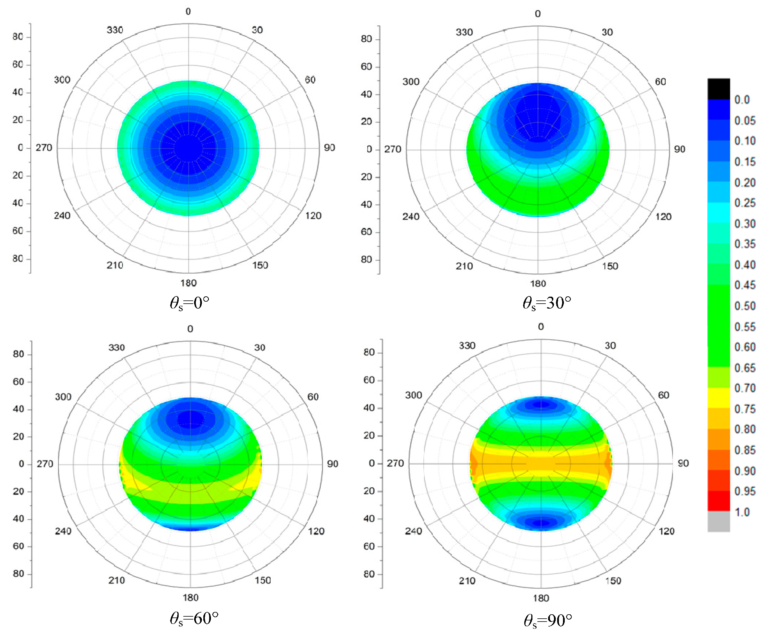
Figure 5.
The AOP (angle of polarization) patterns of skylight transmitted through a calm water surface within the Snell’s window at different solar zenith angle θs = 0°, 30°, 60°, 90°, the AOP ranges from 0 to 1, and the reference plane is the meridian of each observation direction.
Figure 5.
The AOP (angle of polarization) patterns of skylight transmitted through a calm water surface within the Snell’s window at different solar zenith angle θs = 0°, 30°, 60°, 90°, the AOP ranges from 0 to 1, and the reference plane is the meridian of each observation direction.

Figure 6.
The intensity distributions of skylight transmitted through a calm water surface within the Snell’s window at different solar zenith angle θs = 0°, 30°, 60°, 90°, the intensity range from 0 to 1.
Figure 6.
The intensity distributions of skylight transmitted through a calm water surface within the Snell’s window at different solar zenith angle θs = 0°, 30°, 60°, 90°, the intensity range from 0 to 1.

Figure 7.
The DOP patterns of full incident light transmitted through a wavy water surface under different SZAs, where wind speed is 5 m/s, wind direction is 0°.
Figure 7.
The DOP patterns of full incident light transmitted through a wavy water surface under different SZAs, where wind speed is 5 m/s, wind direction is 0°.
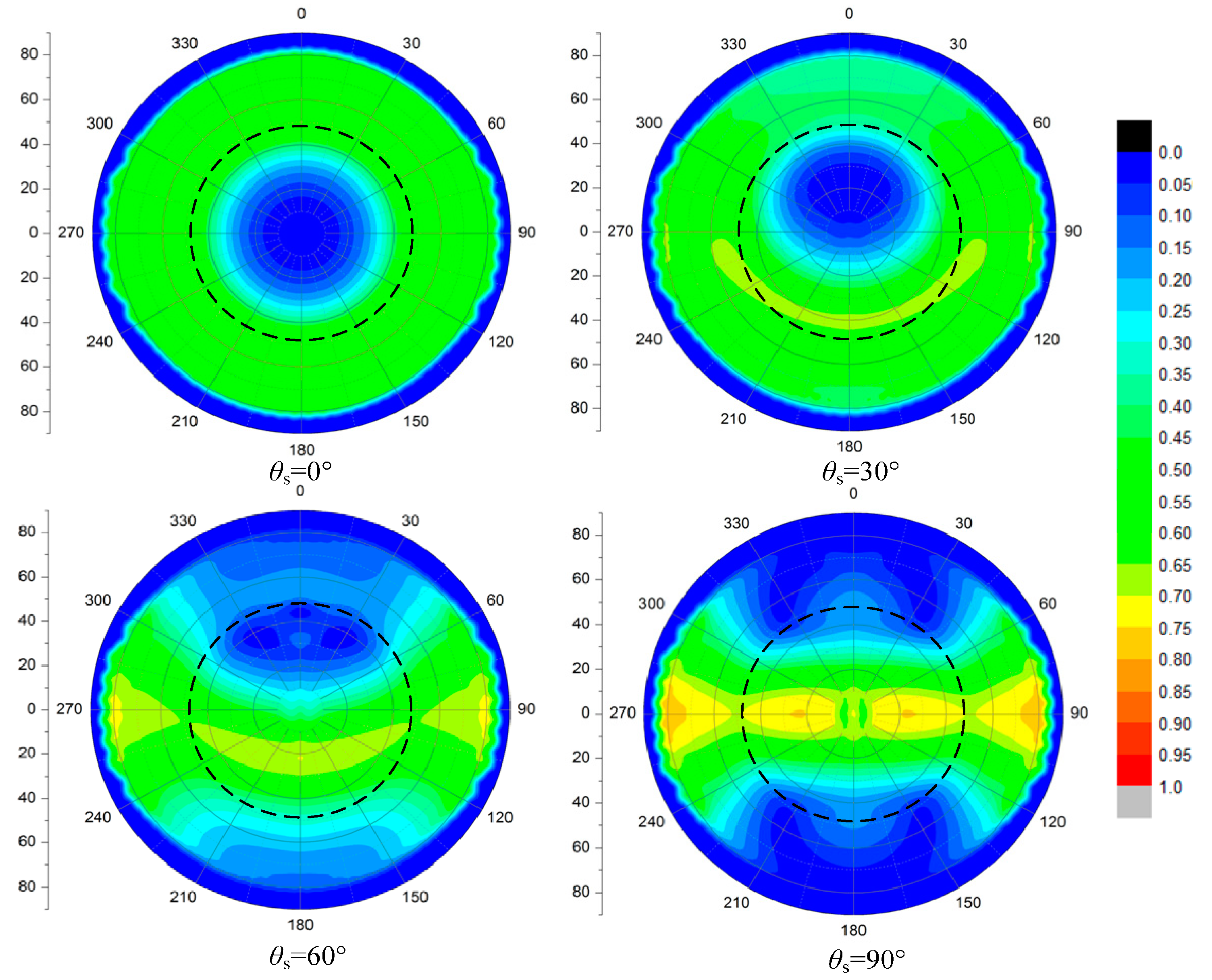
Figure 8.
The AOP patterns of full incident light transmitted through a wavy water surface under different SZAs, where wind speed is 5 m/s, wind direction is 0°.
Figure 8.
The AOP patterns of full incident light transmitted through a wavy water surface under different SZAs, where wind speed is 5 m/s, wind direction is 0°.

Figure 9.
The intensity distributions of transmitted light under a wavy water surface with different SZAs, where wind speed is 5 m/s, wind direction is 0°.
Figure 9.
The intensity distributions of transmitted light under a wavy water surface with different SZAs, where wind speed is 5 m/s, wind direction is 0°.

Figure 10.
The DOP, AOP and intensity patterns of transmitted light under a wavy water surface with different wind speeds, where the SZA is 30°, wind direction is 0°.
Figure 10.
The DOP, AOP and intensity patterns of transmitted light under a wavy water surface with different wind speeds, where the SZA is 30°, wind direction is 0°.

Figure 11.
The DOP, AOP and intensity patterns of transmitted light under a wavy water surface with different incident sources (the direct solar light, scattering skylight and combination of above), where the SZA is 30°, wind speed is 5 m/s, and wind direction is 0°.
Figure 11.
The DOP, AOP and intensity patterns of transmitted light under a wavy water surface with different incident sources (the direct solar light, scattering skylight and combination of above), where the SZA is 30°, wind speed is 5 m/s, and wind direction is 0°.
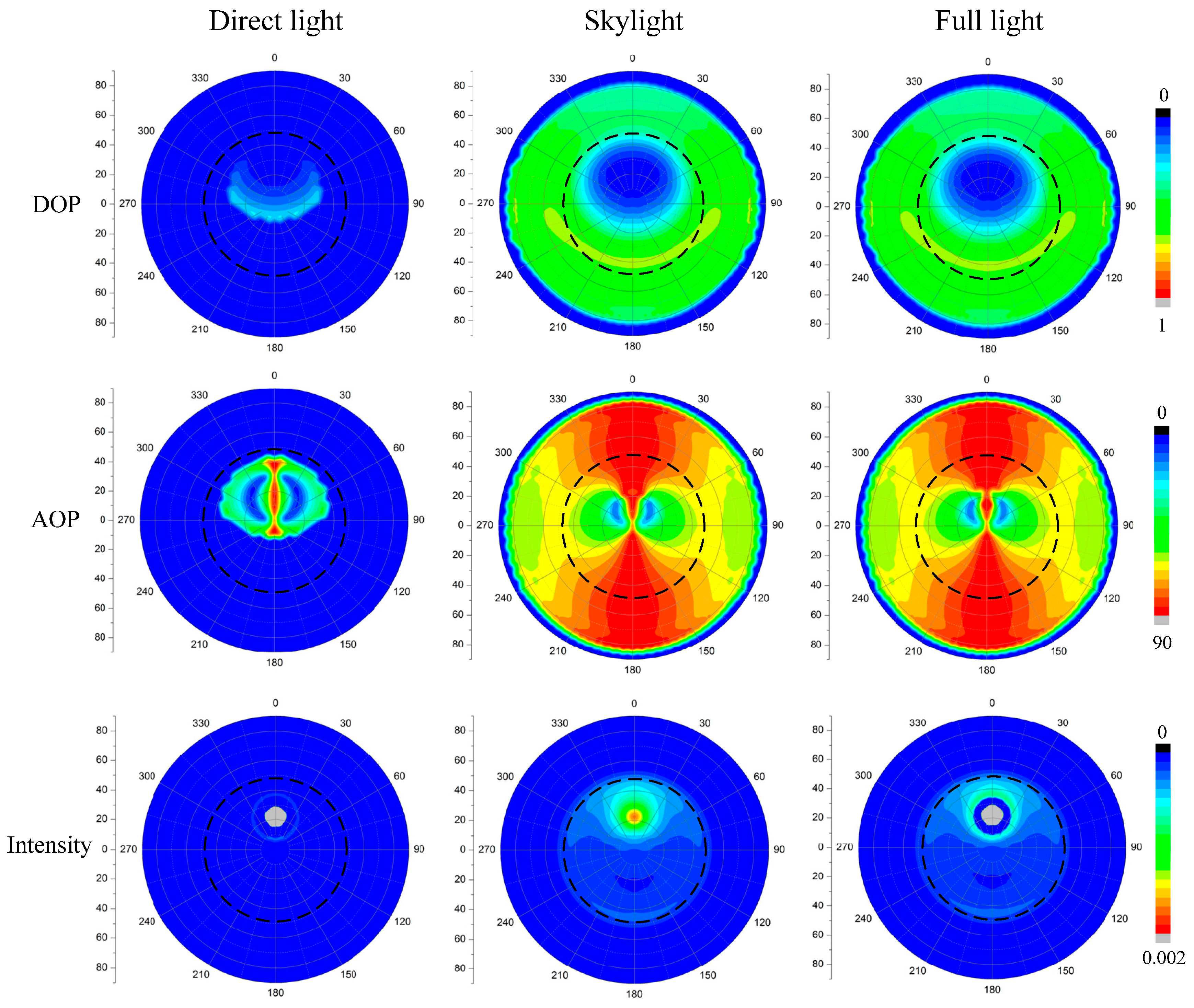
Figure 12.
The DOP patterns of the: skylight (A); reflected light (B); and refracted light (C) under different SZAs (30°, 60° and 90°), where the wind speed is 5 m/s, and wind direction is 0°.
Figure 12.
The DOP patterns of the: skylight (A); reflected light (B); and refracted light (C) under different SZAs (30°, 60° and 90°), where the wind speed is 5 m/s, and wind direction is 0°.

Figure 13.
The AOP patterns of the: skylight (A); reflected light (B); and refracted light (C) under different SZAs (30°, 60° and 90°), where the wind speed is 5 m/s, and wind direction is 0°.
Figure 13.
The AOP patterns of the: skylight (A); reflected light (B); and refracted light (C) under different SZAs (30°, 60° and 90°), where the wind speed is 5 m/s, and wind direction is 0°.
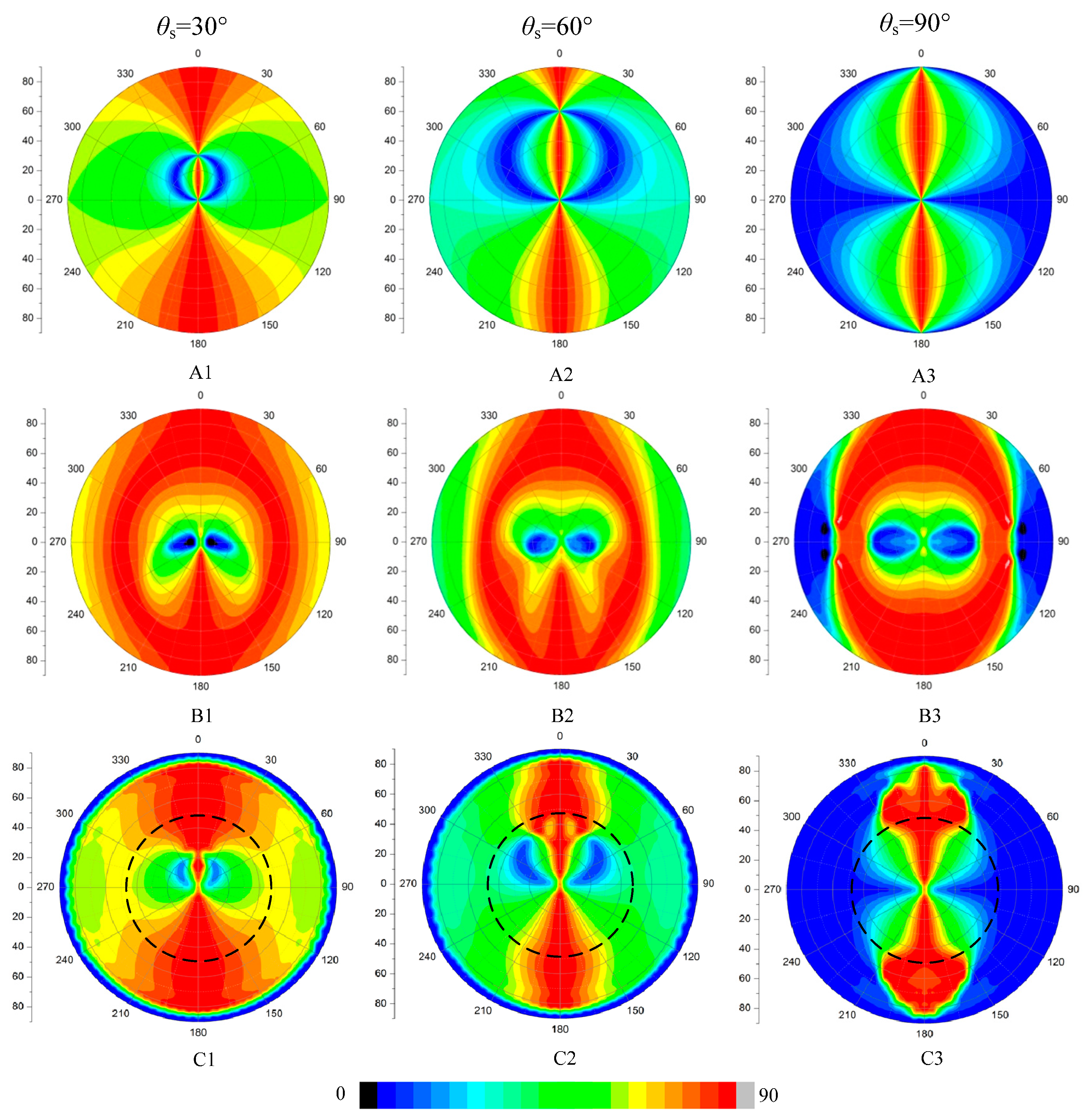
Figure 14.
Radiance of downwelling light field. In this and the following figures, the zenith angle for the data increases linearly with the radius from the center. The sun is towards the top of the image and the solar zenith angle is 90°. (A) Data adopted from Bhandari’s work [24]; and (B) simulated results using our model. The white circle indicates the Snell’s cone.
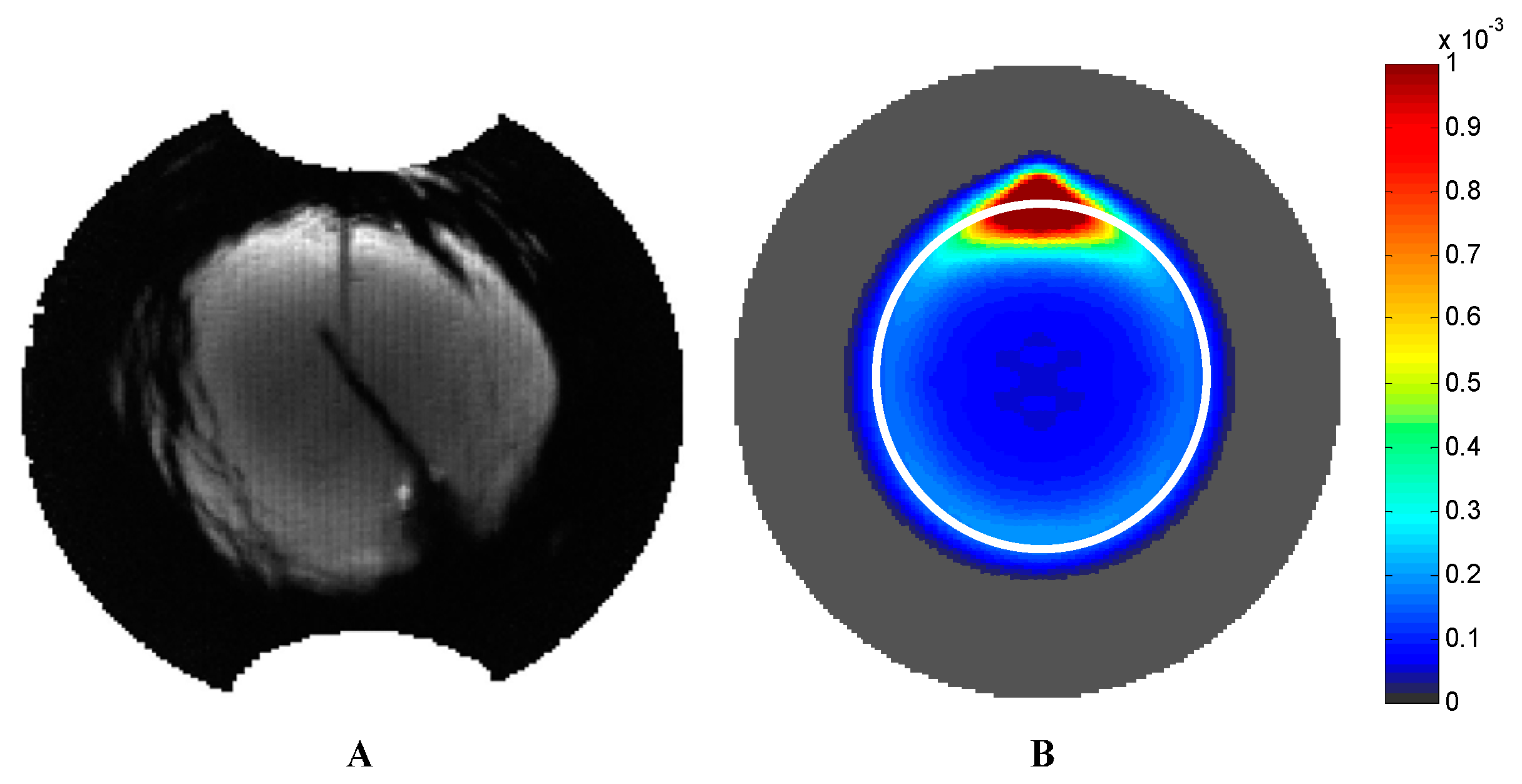
Figure 15.
Q/I (A); and U/I (B) graphs measured by Bhandari [24]. Simulated: Q/I (C); and U/I (D) graphs.
Figure 15.
Q/I (A); and U/I (B) graphs measured by Bhandari [24]. Simulated: Q/I (C); and U/I (D) graphs.

Figure 16.
DOP (A); and AOP (B) graphs measured by Bhandari [24]. Simulated: DOP (C); and AOP (D) graphs.
Figure 16.
DOP (A); and AOP (B) graphs measured by Bhandari [24]. Simulated: DOP (C); and AOP (D) graphs.
© 2017 by the authors. Licensee MDPI, Basel, Switzerland. This article is an open access article distributed under the terms and conditions of the Creative Commons Attribution (CC BY) license (http://creativecommons.org/licenses/by/4.0/).
Share and Cite
MDPI and ACS Style
Zhou, G.; Wang, J.; Xu, W.; Zhang, K.; Ma, Z. Polarization Patterns of Transmitted Celestial Light under Wavy Water Surfaces. Remote Sens. 2017, 9, 324. https://doi.org/10.3390/rs9040324
AMA Style
Zhou G, Wang J, Xu W, Zhang K, Ma Z. Polarization Patterns of Transmitted Celestial Light under Wavy Water Surfaces. Remote Sensing. 2017; 9(4):324. https://doi.org/10.3390/rs9040324
Chicago/Turabian StyleZhou, Guanhua, Jiwen Wang, Wujian Xu, Kai Zhang, and Zhongqi Ma. 2017. "Polarization Patterns of Transmitted Celestial Light under Wavy Water Surfaces" Remote Sensing 9, no. 4: 324. https://doi.org/10.3390/rs9040324
Note that from the first issue of 2016, this journal uses article numbers instead of page numbers. See further details here.